1
POWERED MULTIMEDIA SPEAKERS
YST-MS30/YST-MS35D
SERVICE MANUAL
IMPORTANT NOTICE
This manual has been provided for the use of authorized YAMAHA Retailers and their service personnel.
It has been assumed that basic service procedures inherent to the industry, and more specifically YAMAHA
Products, are already known and understood by the users, and have therefore not been restated.
WARNING:
Failure to follow appropriate service and safety procedures when servicing this product
may result in personal injury, destruction of expensive components, and failure of the
product to perform as specified. For these reasons, we advise all YAMAHA product
owners that any service required should be performed by an authorized YAMAHA
Retailer or the appointed service representative.
IMPORTANT: The presentation or sale of this manual to any individual of firm does not constitute
authorization, certification or recognition of any applicable technical capabilities,
or establish a principle-agent relationship of any form.
The data provided is believed to be accurate and applicable to the unit(s) indicated on the cover. The research,
engineering, and service departments of YAMAHA are continually striving to improve YAMAHA products.
Modifications are, therefore, inevitable and specifications are subject to change without notice or obligation
to retrofit. Should any discrepancy appear to exist, please contact the distributor's Service Division.
WARNING:
Static discharges can destroy expensive components. Discharge any static electricity
your body may have accumulated by grounding yourself to the ground buss in the unit
(heavy gauge black wires connect to this buss).
IMPORTANT: Turn the unit OFF during disassembly and part replacement. Recheck all work before
you apply power to the unit.
■ CONTENTS
TO SERVICE PERSONNEL ........................................... 1
FRONT AND REAR PANELS ..................................... 1~2
USB PORT OPERATION CHECK TEST ................. 6~13
BLOCK DIAGRAM .................................................. 14~15
SPECIFICATIONS ....................................................... 3~4
INTERNAL VIEW ............................................................ 4
PRINTED CIRCUIT BOARD ................................... 16~17
SCHEMATIC DIAGRAM ............................................... 18
DISASSEMBLY PROCEDURES .................................... 5
PARTS LIST ............................................................ 19~27
100695
YST-MS30/YST-MS35D
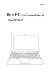
YST-MS30 YST-MS35D
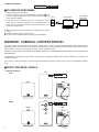
■ TO SERVICE PERSONNEL
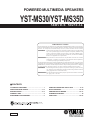
1. Critical Components information.
and
Components having special characteristics are marked
must be replaced with parts having specifications equal to
those originally installed.
WALL
OUTLET
EQUIPMENT
UNDER TEST
AC LEAKAGE
TESTER OR
EQUIVALENT
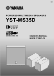
2. Leakage Current Measurement (For 120V Model only).
When service has been completed, it is imperative that you
verify that all exposed conductive surfaces are properly insulated from supply circuits.
INSULATING
TABLE
● Meter impedance should be equivalent to 1500 ohm shunted by
0.15µF.
● Leakage current must not exceed 0.5mA.
● Be sure to test for leakage with the AC plug in both polarities.
WARNING: CHEMICAL CONTENT NOTICE!
The solder used in the production of this product contains LEAD. In addition, other electrical/electronic and/or plastic (where
applicable) components may also contain traces of chemicals found by the California Health and Welfare Agency (and possibly
other entities) to cause cancer and/or birth defects or other reproductive harm.
DO NOT PLACE SOLDER, ELECTRICAL/ELECTRONIC OR PLASTIC COMPONENTS IN YOUR MOUTH FOR ANY REASON
WHATSOEVER!
Avoid prolonged, unprotected contact between solder and your skin! When soldering, do not inhale solder fumes or expose eyes
to solder/flux vapor!
If you come in contact with solder or components located inside the enclosure of this product, wash your hands before handling
food.
■ FRONT AND REAR PANELS
•
Satellite Speakers
Left
Top
YST-MS35D only
Front
Rear
Top
Right
YST-MS35D only
Front
1
Rear
YST-MS30/YST-MS35D
YST-MS30 YST-MS35D
•
Subwoofer
Front
Top
YST-MS35D only
Rear
YST-MS35D
U and C models only
YST-MS35D
U and C models only
YST-MS35D only
A model only
B and G models only
2
YST-MS30/YST-MS35D
YST-MS30 YST-MS35D
■ SPECIFICATIONS
Type
Advanced Yamaha Active Servo Technology
(Advanced Y. S. T)
Dimensions (W x H x D)
Satellite
65x75x119mm
(2.6"x3"x7-4.7")
Output Power
Satellite
Subwoofer
6W+6W (1kHz, 4 ohms at T.H.D.=10%)
18W (100Hz, 4 ohms at T.H.D.=10%)
Input Sencitivity
Input Impedance
200mV (1kHz, 4 ohms at 6W)
20 kohms
Frequency Response
Satellite+Subwoofer
Crossover Frequency
Satellite/Subwoofer
45Hz to 20kHz
fc=180Hz
Subwoofer
183x196x183mm
(7.2"x7.7"x7.2")
Weight
Satellite
Left: 0.36kg (13 oz.)
Right: 0.45kg (1Ibs.)
2.3kg (5Ibs. 1oz.)
Subwoofer
Finish
YST-MS30
Speaker Unit
Satellite :
5cm(2") cone (JA05U8),
YST-MS30W
YST-MS30B
Computer white color
Black color
Subwoofer:
Magnetic Shielding Type
12cm(5") cone (JA1286),
YST-MS35D
YST-MS35DW
Computer white color
Magnetic Shielding Type
YST-MS35DB
Accessories
Input Sction
YST-MS30
Subwoofer
YST-MS35D
Subwoofer
Black color
YST-MS30
3.5mm stereo mini jack for audio-signal x2
AC adapter (DC15V, 1.2A)x1
3.5mm stareo mini jack for audio-signal x2
3.5mm stereo mini plug cable with black color(1.8m) x1
8 pcs of nonskid pads x1set
Subwoofer
Output Sction
USB digital x1
Subwoofer
RCA pin jack connected to Left speaker
8 pin jack connected to Right speaker
3.5mm stereo mini plug cable with black color(1.8m) x1
USB cable (2m) x1
(standby/on)Switch
8 pcs of nonskid pads x1set
CD-ROM x1
AC adapter (DC15V, 1.2A)x1
Operating Section
Satellite
Subwoofer
Power Supply(AC adapter)
U, C models
A models
B, G models
YST-MS35D
Volume control
Bass control
AC120V/60Hz
AC240V/50Hz
AC230V/50Hz
System Requirements YST-MS35D
OS: Microsoft Windows 98
CPU: 200 MHz or faster Intel Pentium MMX processor or
equivalent
HDD: At least 10 MB available space
CD-ROM drive for driver installation
USB port compatible with USB standards ver 1.0
* Specifications subject to change without votice.
U ....... U. S. A. model
B ....... British model
C ....... Canadian model G ....... European model
A ....... Australian model
Intel and Pentium are registered trademarks and MMX is a
trademark of Intel Corporation.
Windows is a registered trademark of Microsoft Corporation
in the United States and/or other countries.
All other trademarks are property of their respective owners.
3
YST-MS30/YST-MS35D
YST-MS30 YST-MS35D
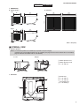
•
DIMENSIONS
▼ Satellite Speaker
▼ Subwoofer
Left
,,,,,,,,,,,,,,,,,,
,,,,,,,,,,,,,,,,,,
,,,,,,,,,,,,,,,,,,
,,,,,,,,,,,,,,,,,,
,,,,,,,,,,,,,,,,,,
,,,,,,,,,,,,,,,,,,
,,,,,,,,,,,,,,,,,,
,,,,,,,,,,,,,,,,,,
,,,,,,,,,,,,,,,,,,
,,,,,,,,,,,,,,,,,,
,,,,,,,,,,,,,,,,,,
,,,,,,,,,,,,,,,,,,
,,,,,,,,,,,,,,,,,,
,,,,,,,,,,,,,,,,,,
,,,,,,,,,,,,,,,,,,
,,,,,,,,,,,,,,,,,,
,,,,,,,,,,,,,,,,,,
196
(7.7")
65
(2.6")
,,,
,,,
,,,
,,,
,,,
,,,
,,,
,,,
,,,
,,,
,,,
,,,
,,,
,,,
,,,
,,,
,,,
8.2
(0.3)
65
(2.6")
65
(2.6")
75
(3")
,,,,,,,,,,,,,,,,,,
,,,,,,,,,,,,,,,,,,
,,,,,,,,,,,,,,,,,,
,,,,,,,,,,,,,,,,,,
,,,,,,,,,,,,,,,,,,
,,,,,,,,,,,,,,,,,,
,,,,,,,,,,,,,,,,,,
,,,,,,,,,,,,,,,,,,
,,,,,,,,,,,,,,,,,,
,,,,,,,,,,,,,,,,,,
,,,,,,,,,,,,,,,,,,
,,,,,,,,,,,,,,,,,,
,,,,,,,,,,,,,,,,,,
,,,,,,,,,,,,,,,,,,
,,,,,,,,,,,,,,,,,,
,,,,,,,,,,,,,,,,,,
,,,,,,,,,,,,,,,,,,
Right
75
(3")
183
(7.2")
183
(7.2")
,,,,,,,,,,,,,,,,,,,,,,,,,,,,,,,,,,
,,,,,,,,,,,,,,,,,,,,,,,,,,,,,,,,,,
,,,,,,,,,,,,,,,,,,,,,,,,,,,,,,,,,,
,,,,,,,,,,,,,,,,,,,,,,,,,,,,,,,,,,
,,,,,,,,,,,,,,,,,,,,,,,,,,,,,,,,,,
,,,,,,,,,,,,,,,,,,,,,,,,,,,,,,,,,,
,,,,,,,,,,,,,,,,,,,,,,,,,,,,,,,,,,
,,,,,,,,,,,,,,,,,,,,,,,,,,,,,,,,,,
,,,,,,,,,,,,,,,,,,,,,,,,,,,,,,,,,,
,,,,,,,,,,,,,,,,,,,,,,,,,,,,,,,,,,
,,,,,,,,,,,,,,,,,,,,,,,,,,,,,,,,,,
,,,,,,,,,,,,,,,,,,,,,,,,,,,,,,,,,,
,,,,,,,,,,,,,,,,,,,,,,,,,,,,,,,,,,
,,,,,,,,,,,,,,,,,,,,,,,,,,,,,,,,,,
,,,,,,,,,,,,,,,,,,,,,,,,,,,,,,,,,,
,,,,,,,,,,,,,,,,,,,,,,,,,,,,,,,,,,
,,,,,,,,,,,,,,,,,,,,,,,,,,,,,,,,,,
,,,,,,,,,,,,,,,,,,,,,,,,,,,,,,,,,,
,,,,,,,,,,,,,,,,,,,,,,,,,,,,,,,,,,
,,,,,,,,,,,,,,,,,,,,,,,,,,,,,,,,,,
,,,,,,,,,,,,,,,,,,,,,,,,,,,,,,,,,,
,,,,,,,,,,,,,,,,,,,,,,,,,,,,,,,,,,
,,,,,,,,,,,,,,,,,,,,,,,,,,,,,,,,,,
,,,,,,,,,,,,,,,,,,,,,,,,,,,,,,,,,,
,,,,,,,,,,,,,,,,,,,,,,,,,,,,,,,,,,
,,,,,,,,,,,,,,,,,,,,,,,,,,,,,,,,,,
,,,,,,,,,,,,,,,,,,,,,,,,,,,,,,,,,,
,,,,,,,,,,,,,,,,,,,,,,,,,,,,,,,,,,
,,,,,,,,,,,,,,,,,,,,,,,,,,,,,,,,,,
,,,,,,,,,,,,,,,,,,,,,,,,,,,,,,,,,,
,,,,,,,,,,,,,,,,,,,,,,,,,,,,,,,,,,
,,,,,,,,,,,,,,,,,,,,,,,,,,,,,,,,,,
,,,,,,,,,,,,,,,,,,,,,,,,,,,,,,,,,,
,,,,,,,,,,,,,,,,,,,,,,,,,,,,,,,,,,
,,,,,,,,,,,,,,,,,,,,,,,,,,,,,,,,,,
,,,,,,,,,,,,,,,,,,,,,,,,,,,,,,,,,,
,,,,,,,,,,,,,,,,,,,,,,,,,,,,,,,,,,
,,,,,,,,,,,,,,,,,,,,,,,,,,,,,,,,,,
,,,,,,,,,,,,,,,,,,,,,,,,,,,,,,,,,,
,,,,,,,,,,,,,,,,,,,,,,,,,,,,,,,,,,
,,,,,,,,,,,,,,,,,,,,,,,,,,,,,,,,,,
,,,,,,,,,,,,,,,,,,,,,,,,,,,,,,,,,,
,,,,,,,,,,,,,,,,,,,,,,,,,,,,,,,,,,
,,,,,,,,,,,,,,,,,,,,,,,,,,,,,,,,,,
,,,,,,,,,,,,,,,,,,,,,,,,,,,,,,,,,,
,,,,,,,,,,,,,,,,,,,,,,,,,,,,,,,,,,
,,,,,,,,,,,,,,,,,,,,,,,,,,,,,,,,,,
,,,,,,,,,,,,,,,,,,,,,,,,,,,,,,,,,,
,,,,,,,,,,,,,,,,,,,,,,,,,,,,,,,,,,
,,,,,,,,,,,,,,,,,,,,,,,,,,,,,,,,,,
,,,,,,,,,,,,,,,,,,,,,,,,,,,,,,,,,,
,,,,,,,,,,,,,,,,,,,,,,,,,,,,,,,,,,
,,,,,,,,,,,,,,,,,,,,,,,,,,,,,,,,,,
,,,,,,,,,,,,,,,,,,,,,,,,,,,,,,,,,,
,,,,,,,,,,,,,,,,,,,,,,,,,,,,,,,,,,
,,,,,,,,,,,,,,,,,,,,,,,,,,,,,,,,,,
,,,,,,,,,,,,,,,,,,,,,,,,,,,,,,,,,,
,,,,,,,,,,,,,,,,,,,,,,,,,,,,,,,,,,
,,,,,,,,,,,,,,,,,,,,,,,,,,,,,,,,,,
,,,,,,,,,,,,,,,,,,,,,,,,,,,,,,,,,,
119
(4.7")
65
(2.6")
119
(4.7")
,,,
,,,
,,,
,,,
,,,
,,,
,,,
,,,
,,,
,,,
,,,
,,,
,,,
,,,
,,,
,,,
,,,
Units : mm (inch)
■ INTERNAL VIEW
• Satellite Speakers
Notes: The Satellite Speakers are available by the speaker unit (Left or Right).
Individual parts of the Satellite Speakers are not available. (See page 23 and 24 of the PARTS LIST for YST-MS30,
page 25 and 26 of the PARTS LIST for YST-MS35D.)
▼ Left
▼ Right
1
2
3
1 Satellite Speaker Unit L
2 Satellite Speaker Unit R
3 P. C. B. AMP (3)
•
Subwoofer
5
4 Speaker Unit
5 P. C. B. AMP (1)
6 P. C. B. AMP (4)
(YST-MS35D only)
7 P. C. B. MAIN (2)
4
6
7
4
YST-MS30/YST-MS35D
YST-MS30 YST-MS35D
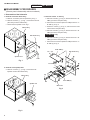
■ DISASSEMBLY PROCEDURES
(Remove parts in disassembly order as numbered.)
•
Disassemble of the Subwoofer
1. Removal of the Rear Panel Ass'y.
a. Remove 1 knob from the rear panel ass'y in Fig. 1.
b. Remove 8 screws ( 1 ) in Fig. 1, and remove the rear
panel ass'y from the cabinet ass'y.
c. Disconnect the speaker cord in Fig. 1.
3. Removal of the P. C. B. Ass'y
a. Remove 2 screws (3) in Fig. 3, and remove the P. C. B.
AMP (1) from the rear panel ass'y.
b. Disconnect 2 connectors (CN1 and CN3) from the P. C.
B. AMP (1) in Fig. 3.
c. Remove 4 screws (4) in Fig. 3, and remove the mold
Cabinet Ass'y
case from the rear panel ass'y.
d. Remove 3 screws (5) in Fig. 3, and remove the P. C. B.
AMP (2) from the rear panel ass'y.
Rear Panel Ass'y
YST-MS35D only
e. Remove 2 screws (6) in Fig. 3, and remove the P. C. B.
AMP (4) from the rear panel ass'y.
f. Disconnect 2 connectors (CN2 and CN5) from the P. C.
B. AMP (4) in Fig. 3.
1
P.C.B. AMP (1)
CN1
Rear Panel Ass'y
CN3
Speaker Cord
3
Knob
Fig. 1
6
P.C.B. AMP (4)
5
2. Removal of the Speaker Unit
a. Remove 4 screws ( 2 ) in Fig. 2, and remove the
CN2
4
CN5
speaker unit from the cabinet ass'y.
CN3
Cabinet Ass'y
P.C.B. AMP (2)
CN1
Speaker Unit
Mold Case
Fig. 3
2
Fig. 2
5
YST-MS30/YST-MS35D
YST-MS35D
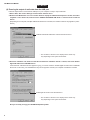
■ USB PORT OPERATION CHECK TEST
The YST-MS35D has a USB port. This USB port operation is checked be necessary whether or not normal state.
1. Installing and verifying the YST-MS35D speaker device drivers
Please follow these steps to install the Yamaha YST-MS35D speaker device drivers in your Windows 98 system using the
included CD-ROM, and verify that Windows 98 recognizes the installed device drivers and that CD audio, sound generated
while using software, and system sounds from the personal computer will be output via the USB port.
(1) Measuring instruments
• Personal Computer (Windows 98)
• CD-ROM (Accessory)
• USB Cable (Accessory)
• AC adapter (Accessory)
(2) System requirements
For digital audio streaming using a USB connection:
OS: Microsoft Windows 98
CPU: 200 MHz or faster Intel Pentium MMX processor or equivalent
HDD: At least 10 MB available space
CD-ROM drive for driver installation
USB port compatible with USB standards ver 1.0
(3) Installing the speaker device drivers
Notes:
• Do not connect the PC and the subwoofer using the USB cable before installing the YST-MS35D device
drivers. If you accidentally connect them, refer to “(5) Re-installing the Device Driver” on page 8.
• Before starting, check “(2) System Requirements” section, above, to see that your PC supports YST-MS35D.
• Make sure that no other CD-ROM is loaded in the CD-ROM drive and that you quit all application programs.
• Have your Windows 98 CD-ROM ready when you install the Yamaha YST-MS35D speaker device drivers. You may
need it in some cases.
• The installation procedure may differ from the following instructions depending on the system environment. Follow
the instructions that appear in the dialog box. Please contact your computer’s manufacturer or dealer if you have any
questions.
1. Connect the YST-MS35D speakers and connect the AC adapter to the AC receptacle. At this time, do not
connect the subwoofer to the computer using the USB cable.
2. Turn on your PC and start Windows 98.
3. Insert the YAMAHA YST-MS35D CD-ROM into the CD-ROM or DVD-ROM drive.
If the Windows 98 Autorun feature is turned on, the installation start up screen appears automatically.
4. Continue with the installation as prompted.
If the Windows 98 Autorun feature is not turned on, you must start the installation manually, as explained below.
5. Double-click the My Computer icon.
The My Computer window opens.
6. Double-click the “Yamaha” CD-ROM icon.
The installation start up screen appears.
7. Continue with the installation as prompted.
8. After the installation is completed, connect the subwoofer to the computer using the USB cable.
6
YST-MS30/YST-MS35D
YST-MS35D
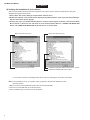
(4) Verifying the installation of device drivers
After you have installed the device drivers as explained in the previous section, follow the steps below to verify that
Windows 98 recognizes these drivers.
1. Select “Start,” then select “Settings-->Control Panel” from the menu.
2. Double-click “System” in the control Panel to display the “System Properties” panel, select the “Device Manager”
tab, then select “View devices by type.”
3. Click the plus sign (+) for “Human Interface Devices,” “Sound, video and game controllers,” and “Universal Serial
Bus Controller” in the device list, and check to see if “Human Interface Devices,” “YAMAHA YST-MS35D USB
Audio,” and “YAMAHA YST-MS35D USB Composite Device” as shown below.
Select "View devices by type".
"Human Interface Devices" is listed.
Select "View devices by type".
"YAMAHA YST-MS35D USB Composite Device" is listed.
"AMAHA YST-MS35D USB Audio" is listed.
• The contents of the list on the display shown above may vary depending on the system environment.
Note: If an exclamation point (!), or a question mark (?) appears to the left of the USB device name,
check the ollowing:
1. Make sure that you have installed the drivers from the included CD-ROM.
2. Check to see if the USB cable is connected securely.
3. The AC adapter plug is connected to the AC receptacle.
7
YST-MS30/YST-MS35D
YST-MS35D
(5) Re-installing the Device Driver
If you connect the PC and the YST-MS35D via the USB ports using the USB cable before you install the included application
software, the YST-MS35D device driver will not recognize the devices correctly, and will display the following items in the
“System Properties” window:
• USB Audio Device in the list of “Sound, video and game controllers”
• USB Composite Device in the list of “Universal serial bus controller”
To recognize the devices correctly, re-install the driver following the steps below:
1. Make sure the YST-MS35D is connected to the PC via the USB cable.
2. Click the “+” symbol next to “Universal serial bus controller” to display the list.
3. Make sure that “USB Composite Device” appears in the list and click to select it.
"USB Composite Device" is listed.
4. Click [Remove].
The dialog shown below appears. Click [OK].
“USB Audio Device” will be deleted.
5. Make sure that “USB Composite Device” has been deleted from the list of “Universal serial bus controller.”
6. Disconnect the USB cable.
7. Insert the included CD-ROM into the CD-ROM drive and re-install the device driver.
8. Check the device driver. Refer to “(4) Verifying the installation of device drivers” on page 7.
8
YST-MS30/YST-MS35D
YST-MS35D
(6) Ensuring the output of audio data from the USB port
Follow the steps below to ensure that the USB port on your computer is ready to output CD audio.
1. Select “Start,” then select “Settings-->Control Panel” from the menu.
2. Double-click “Multimedia” icon in the Control Panel to display the “Multimedia Properties” window, and under
“Playback” in the “Audio” tab, make sure that “YAMAHA YST-MS35D USB Audio” is selected as the “Preferred
device.”
(Depending on the computer, if multiple USB audio devices are connected, the number of devices may appears in parentheses.)
"YAMAHA YST-MS35D USB Audio" selected as Preferred device
• The contents of the list on the display shown at left may
vary depending on the system environment.
3. Select the “CD Music” tab, make sure that the text below the “CD Music Volume” is Active, and check “Enable
digital CD audio for this CD-ROM device.”
If the text below “CD Music Volume” appears in gray, you cannot check the “Enable digital CD audio for this CD-ROM
device” box. In this case, your CD-ROM drive may not be supported. Consult your computer manufacturer or dealer.
Enable digital CD audio for this CD-ROM device
• The contents of the list on the display shown at left may
vary depending on the system environment.
Now you are ready to enjoy your YST-MS35D Speaker System!
9
YST-MS30/YST-MS35D
YST-MS35D
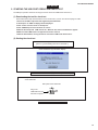
2. STARTING THE USB PORT OPERATION CHECK TEST
The USB port operation check test is using the tool for check test "USB Check Version X.X".
(1) Downloading the tool for check test
Pease follow these steps to download the tool for check test in your PC from the homepage of "USB".
1. Access to the URL "http://www.usb.org/developers/index.html".
2. "developers" of "USB" homepage will be displayed.
3. Click "Tools" from the menu of "developers".
4. Click "USBComp.exe" from the menu of "Tools".
5. After the file unzips and "USB Check" file, "Hidview" file, and all needed drivers appear.
6. Make sure that "USB Check" file appears and click to select it.
7. After the downloaded, running the tool for check test "USB Check Version X.X".
(2) Starting the check test
Downloading the tool for check test.
[refer to "(1) Downloading the tool for check test".].
↓
"PLUG IN DEVICE (S) TO TEST!" display.
↓
Connect the USB cable to the USB port of the personal computer.
↓
Plug in the USB cable from Personal Computer to "USB INPUT" on the rear panel
of the Subwoofer.
Rear panel of the Subwoofer
Plug in the
USB Cable from the
Personal Computer.
USB
INPUT
↓
Start the USB port operation check test.
10
YST-MS30/YST-MS35D
YST-MS35D
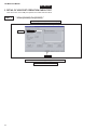
3. DETAIL OF USB PORT OPERATION CHECK TEST
There are 5 items in the USB port operation check test as shown below.
TEST 1
" 00Vid (0X0499) Pid (0X3002) "
"USB Compliance Tool, Version 2.6" display.
↓
Confirm the " 99 Vid (0X0499) Pid (0X3002)".
Confirmed.
Click.
↓
Confirmation of USB EEPROM (IC201) opration is completed.
↓
Click the "Full Test" for next test.
11
YST-MS30/YST-MS35D
YST-MS35D
TEST 2
All is checked ("✔").
"USB Chapter 9 Test" display.
↓
Confirm that all is checked ("✔").
Confirmed.
Click.
↓
Click the "Start Automated Testing" for next test.
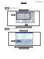
TEST 3
" Error Count : 0 "
"Full Test Results" display.
↓
Confirm the " Error Count : 0 ".
Confirmed.
↓
Operation of between USB IC and USB port is normal state.
↓
Enter automated to next test.
12
YST-MS30/YST-MS35D
YST-MS35D
TEST 4
" OK "
"USB Compliance Tool" display.
↓
Confirm the " OK ".
Confirmed.
↓
Enter automated to next test.
TEST 5
" OK "
"DEVICE IS HID" display.
↓
Confirm the " OK ".
Confirmed.
↓
Completed the USB port operation check test.
13
YST-MS30/YST-MS35D
YST-MS30 YST-MS35D
■ BLOCK DIAGRAM
• Subwoofer
• Satellite Speaker Unit (Right)
VCC
VOLUME
VR2
JK1
7
8
IC1
JK5
1 IR
IR
INPUT 1
TO RIGHT
SPEAKER
VCC
JK2
3
IL
2
IC1
1
3
6
YST-MS35D only
EEPROM
USB D/A Converter
IC202
IC201
Regulator (MC24C02-W-BN6) (UDA1321PS/N101)
WP
SDA
SCL
5
31
6
30
SDA
SCL
VOUTR
VOUTL
CN2
W202
2 Rch
2
24
3
7
4 IL
IL
4
Q1
Vcc
3 Lch
7
3
6
6 D–
7 D+
XTAL1
XTAL2
OL
3
5 VCC
VCC
2
2 E2
E2
5
8 PWS
PWS
1
6 RSP+
RSP+
8
9 RSPG
RSPG 9
Vcc
5
8
PWS
VSS
Vcc
2
4
7
Vcc 7 OL
2
RSP+
Q3
3
9
(Standby/ON)
+
–
STAND-BY
6
8
IC2
15
11
INPUT4–
OUT4
14
H. P. F
XL201
48MHz
6dB/oct
Power Amp
IC4
(TDA7370BV)
TO LEFT
SPEAKER
JK3
3
2
IC2
12
OUT3
INPUT3
15
LSP+
• Satellite Speaker Unit (Left)
JK3
LSP+
+
H. P. F
DC15V
Vcc
Regulator
From
AC
adaptor
BIAS
3
IC3
6
2
L. P. F
RSPG
LSPG
–6dB/oct
3
Vcc
VR1
8
IC3
7
H. P. F
BASS
4
8
IC6
–
LSPG
SATELLITE
Lch
9
13
+B
Vcc
Vcc
BIAS
P.G
LSPG
6dB/oct
IC6
IN
OUT
GND
JK4
SATELLITE
Rch
7
14
Vcc
BIAS
+B
SW1
JK5
Mute
L202
2
USB
INPUT
OL
21
VDD
JK202
OR
Q2
E2
OR
Q201 +3.3V
7
3 OR
Switch
RSPG
INPUT 2
W201
CN5
1 VDD 1
IR
CN4
6
VCC
S-GND
VCC
PW-GND
OUT1
INPUT1
8
1
SP –
L. P. F
12dB/oct
SUBWOOFER
–6dB/oct
5
Vcc
BIAS
INPUT2–
OUT2
Vcc
Vcc
SP +
2
Vcc
BIAS
Q6
Q4
2
IC8
4
8
IC8
7
8
IC7
7
2
IC7
BIAS
Q5
4
A. N. I. C
Limitter
14
15
A
B
C
D
E
F
G
H
YST-MS30/YST-MS35D
YST-MS30 YST-MS35D
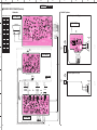
■ PRINTED CIRCUIT BOARD (Foil side)
• Subwoofer
P.C.B. AMP(1)
IC7, 8 : uPC4570HA
IC6 : uPC4570HA
Satellite Speaker Unit (Right)
IC2 : uPC4570HA
W7
+
W3
WH
W4
RE
+B
E
W5
RE
SATELLITE
Rch
W6
WH
TDA7370BV
R
W2
From
Subwoofer
JK5
USB
INPUT
P.C.B. AMP(4)
3
2
4
1
BL
GR
OR
VI
RE
BR
WH or YE
BE
3
UDA1321PS/N201
W201
E
VDD
RE
Satellite Speaker Unit (Left)
E
Rch
Lch
E
IC202 : M24C02-W-BN6
RE
L
YST-MS35D
only
W202
From
Subwoofer
JK3
4
TO RIGHT
SPEAKER
E
Rch
Lch
E
To
Satellite
Speaker
Unit (Left)
JK3
1
INPUT
2
INPUT
TO LEFT
SPEAKER
+
From
AC
adaptor
JK4
DC 15V
BASS
9
5 2 1 3
8 7 46
W5
RE
IC5 :
NJM78L06A
5
W6
WH
16
6
VDD
E
RE
RE
OL
OR
SWI
VCC
E
BIAS
LSP+
RSP+
PSW1
IC1, 3 : uPC4570HA
P.C.B. AMP(2)
SATELLITE
Lch
–
To
Satellite
Speaker
Unit (Right)
JK5
RE
W1
+
–
P.C.B. AMP(3)
RE
VOLUME
OL
OR
SWI
VCC
E
BIAS
LSP+
RSP+
PSW1
SUBWOOFER
PSW
VCC
OL
IL
E2
IR
OR
RSP+
RSPG
2
● Semiconductor Location
Ref. No.
Location
D2
D5
D3
C1
D4
D2
D5
C2
D6
C2
D7
C2
D201
C3
IC1
C5
IC2
E1
IC3
C5
IC4
D2
IC5
D5
IC6
D2
IC7
C2
IC8
C2
IC201
C3
IC202
C3
Q1
G2
Q2
G2
Q3
D5
Q4
C1
Q5
D1
Q6
C1
Q201
C4
• Satellite Speakers
–
1
17
A
C
B
D
E
G
F
H
I
J
K
YST-MS30/YST-MS35D
YST-MS30 YST-MS35D
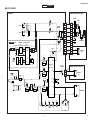
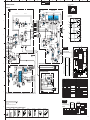
■ SCHEMATIC DIAGRAM
1
IC1~3, 6~8 : uPC4570HA
Dual OP-Amp
• Subwoofer
AMP(2)
AMP(1)
H. P. F
1
POWER AMP
1
L. P. F
15.1
5.9
H. P. F
Vcc
2
2
–
+
+
3
4
5
–
6
7
8
9
Vo1 –Vin1 +Vin1 VEE +Vin2 –Vin2 Vo2 Vcc
5.9
IC4 : TDA7370BV
Quad Power Amp
TDA7370BV
5.9
Vcc
13
Vcc
3
A1
5.9
5.9
OR
15.1
5.9
5.9
8.2
16.7
8.2
0. 8
0. 8
0
0
0. 8
0. 8
10. 4
0
0. 8
0
16. 7
2
8. 2
8. 2
+
OL
INPUT1 4
5.9
5.9
5.9
5.9
SWI
A2 INV.
5.9
15.1
15.1
VCC
+
STAND-BY 7
INPUT2– 5
BIAS
15.1
14.5
WH
LSP+
MUTE
–
A3
RSP+
14.5
2 OUT2
-
E
BASS
1 OUT1
-
RE
PSW1
SUBWOOFER
+
+
15 OUT3
-
5.9
TO RIGHT
SPEAKER
15.1
13.8
INPUT3 12
+B
5.9
3
5.9
A4 INV.
+
E
5.9
5.9
5.9
5.9
15.1
15.1
6
SVR
5.9
5.9
L. P. F
5.9
2
INPUT
19 CLIP DET
INPUT4– 11
5. 9
6.0
5.9
5.9
14 OUT4
-
TO LEFT
SPEAKER
1
INPUT
0
8
PW-GND
9
S-GND
7.0 7.0
5.9
0
5.9
E
JK5
Rch
5.9
15.1
6.0
JK3
5.9
4.2
5.9 5.9
0
5.9
5.9
REGULATOR
5.9
5.9
0
VDD
5.9
From
AC
adapter
5.9
Digital-to-Analog Converter (DAC)
6.0
6.0
5.9
USB D/A
CONVERTER
UDA1321PS/N101
3.2
3.2
1
32 GP1/DI
GP3/WSO
2
31 SDA
GP4/BCKO
3
30 SCL
SHTCB
4
29 GP5/WSI
NC
5
28 NC
3.2
0
0
0
3.2
0
0
0
0
3.2
3.2
0
0
Satellite Speaker Unit (Right)
1.9
0
1.4
1.2
3.2
–
SATELLITE
Lch
6
27 GP0/BCKI
7
26 RTCB
VDDI
8
25 TC
VssI
9
TOP VIEW
VssE 10
23 VDDO
22 VssO
XTAL1 14
19 VssA
XTAL2 15
18 Vref
LEFT DAC
–
+
VOUTL 24
VssX 13
REFERENCE VOLTAGE
XTAL1 14
17 NC
OSC
TIMING
0
SATELLITE
Rch
Name
1
GP2/DO
I/O
∗1
Function
No.
32
GP1/DI
2
GP3/WSO
∗1
31
SDA
I/O
Serial data (I2C-Bus)
3
GP4/BCKO
∗1
30
SCL
I
Serial clock (I2C-Bus)
4
SHTCB
∗2
29
GP5/WSI
5
NC
Unconnected
28
NC
Unconnected
6
D–
I/O
Negative
27
GP0/BCKI
∗1
7
D+
I/O
Positive
26
RTCB
∗2
8
VDDI
Power supply
25
TC
9
VssI
Ground
24
VOUTL
10
VssE
Ground
23
VDDO
Power supply
11
VDDE
Power supply
22
VssO
Ground
12
NC
Unconnected
21
VOUTR
13
VssX
Ground
20
VDDA
Power supply
14
XTAL1
Input
19
VssA
Ground
15
XTAL2
Output
18
Vref
16
VDDX
Power supply
17
NC
Data line of the differential
data bus common to the
USB-standard.
(for digital core)
(for digital I/O)
(for Crystal oscillator)
Name
IC202: M24C02-W-BN6
2k 2.5V CMOS Serial
1
32
Function
∗1
∗1
O
O
O
Lch Output voltage
(for OPE-AMP.)
Rch output voltrage
(for analog)
Reference Voltage
Unconnected
A0
A1
2
Electrically Erasable PROM A2
Vss
(EEPROM)
3
Vcc
8
WP
7
8 Vcc
TOP VIEW
4
HV GENERATOR
7 WP
6 SCL
5 SDA
I/O
CONTROL
LOGIC
MEMORY
CONTROL
LOGIC
XDEC
EEPROM
ARRAY
PAGE LATCHES
TDA7370BV
2SD1200F(Q,R)
M24C02-W-BN6
No.
UDA1321PS/N101
16
9
8
15
1
I/O
∗2
Vss
4
1
PIN CONNECTION DIAGRAM OF DIODES, TRANSISTORS AND IC’s.
DS
23 VDDO
22 VssO
∗2 : Normally connected to ground.
YST-MS35D only
All voltages are measured with a 10MΩ/V DC electric volt meter.
Components having special characteristics are marked
and
must be replaced with parts having specifications equal to those
originally installed.
★ Schematic diagram is subject to change without notice.
★
★
G
21 VOUTR
FOR OPE-AMP
No.
NOTE) ∗1 : Normally unconnected.
Cathode
–
+
18
0
1.COMMON
2.INPUT
3.OUTPUT
VDDI
Vref
E
UPC4570HA
VssI
Rch
7
Anode
RIGHT DAC
0
AMP(3)
NJM78L06A
VDDE
VssE
VDDX 16
–
2SK304(E)
11
10
9
8
3rd-ORDER
NOISE SHAPER
21 VOUTR
20 VDDA
FOR DIGITAL CORE
128fs
0
Rch
FOR DIGITAL I/O
VARIABLE HOLD REGISTER
Lch
+
2SA733(P,Q)
2SC945A(Q,P)
2SC3792
fs
UP-SAMPLE FILTER
XTAL2 15
0
1SS133
MTZJ3.9A
AUDIO FEATURE
PROCESSING DSP
24 VOUTL
VDDE 11
VDDX 16
fs
SAMPLE
FREQUENCY
GENERATOR
E
Lch
0
8
31 SDA
64fs
VssX 13
0
30 SCL
FIFO REGISTERS
D–
NC 12
0
0
1.6
3.2
0
1.6
3.2
0
1.6
6
+
MICROCONTROLLER
GP5/WSI 29
D+
0
REGULATOR
0
USB
INPUT
LSPG
E
3.9
3.2
3.2
3.2
3.2
LSP+
VOLUME
IC201
0
0
0
0
Satellite Speaker Unit (Left)
VDD
DIGITAL I/O
GP0/BCKI 27
GP2/DO
A. N. I. C
9.9
GP4/BCKO 3
GP1/DI 32
• Satellite Speakers
3.2
20 VDDA
19 VssA
GP3/WSO 2
15.1
IC202
M24C02-W-BN6
FOR ANALOG
USB-PROCESSOR
GP2/DO 1
5.9
EEPROM
SHTCB 4
5.9
5.8
5.8
5
6
ANALOG FRONT-END
TEST
CONTROL
BLOCK
RTCB 20
5.6
0
AMP(4)
TC 25
IC201: UDA1321PS/N101
Universal Serial Bus (USB)
15.1
YST-MS35D
only
E
15.2
15.1
5.6
15.1
DC15V
D–
7
YST-MS35D only
5.9
E
5.9
D+
5.9
LIMITTER
Lch
4
5.9
2
1
B
C
E
4
1
Name
I/O Function
No.
Name
I/O
Function
1
A0
∗1
8
Vcc
Power supply
2
A1
∗1
7
WP
∗2
3
A2
∗1
6
SCL
O
Serial clock (I2C-Bus)
4
Vss
Ground
5
SDA
I/O
Serial data (I2C-Bus)
NOTE) ∗1 : Normally connected to ground. ∗2 : Normally connected to power supply.
32
YDEC
SENSE AMP
R/W CONTROL
5
6
SDA SCL
1
18
YST-MS30/YST-MS35D
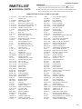
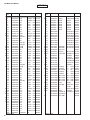
PARTS LIST
■ ELECTRICAL PARTS
■ WARNING
Components having special characteristics are marked ! and must be
replaced with parts having specifications equal to those originally installed.
● Carbon resistors (1/6W or 1/4W) are not included in the ELECTRICAL PARTS
List. For the parts Nos. of the carbon resistores,refer to the last page.
ABBREVIATIONS IN THIS LIST ARE AS FOLLOWS:
C. A. EL. CHP
C. CE
C. CE. ARRAY
C. CE. CHP
C. CE. ML
C. CE. M. CHP
C. CE. SAFTY
C. CE. TUBLR
C. CE. SMI
C. EL
C. MICA
C. ML. FLM
C. MP
C. MYLAR
C. MYLAR. ML
C. PAPER
C. PLS
C. POL
C. POLY
C. PP
C. TNTL
C. TNT. CHP
C. TRIM
CN
CN. BS. PIN
CN. CANNON
CN. DIN
CN. FLAT
CN. POST
COIL. MX. AM
COIL. AT. FM
COIL. DT. FM
COIL. MX. FM
COIL. OUTPT
DIOD. ARRAY
DIODE. BRG
DIODE. CHP
DIODE. VAR
DIOD. Z. CHP
DIODE. ZENR
DSCR. CE
FER. BEAD
FER. CORE
FET. CHP
FL. DSPLY
FLTR. CE
FLTR. COMB
FLTR. LC. RF
GND. MTL
GND. TERM
HOLDER. FUS
IC. PRTCT
JUMPER. CN
JUMPER. TST
L. DTCT
:
:
:
:
:
:
:
:
:
:
:
:
:
:
:
:
:
:
:
:
:
:
:
:
:
:
:
:
:
:
:
:
:
:
:
:
:
:
:
:
:
:
:
:
:
:
:
:
:
:
:
:
:
:
:
CHIP ALUMI. ELECTROLYTIC CAP
CERAMIC CAP
CERAMIC CAP ARRAY
CHIP CERAMIC CAP
MULTILAYER CERAMIC CAP
CHIP MULTILAYER CERAMIC CAP
RECOGNIZED CERAMIC CAP
CERAMIC TUBULAR CAP
SEMI CONDUCTIVE CERAMIC CAP
ELECTROLYTIC CAP
MICA CAP
MULTILAYER FILM CAP
METALLIZED PAPER CAP
MYLAR FILM CAP
MULTILAYER MYLAR FILM CAP
PAPER CAPACITOR
POLYSTYRENE FILM CAP
POLYESTER FILM CAP
POLYETHYLENE FILM CAP
POLYPROPYLENE FILM CAP
TANTALUM CAP
CHIP TANTALUM CAP
TRIMMER CAP
CONNECTOR
CONNECTOR, BASE PIN
CONNECTOR, CANNON
CONNECTOR, DIN
CONNECTOR, FLAT CABLE
CONNECTOR, BASE POST
COIL, AM MIX
COIL, FM ANTENNA
COIL, FM DETECT
COIL, FM MIX
OUTPUT COIL
DIODE ARRAY
DIODE BRIDGE
CHIP DIODE
VARACTOR DIODE
CHIP ZENER DIODE
ZENER DIODE
CERAMIC DISCRIMINATOR
FERRITE BEADS
FERRITE CORE
CHIP FET
FLUORESCENT DISPLAY
CERAMIC FILTER
COMB FILTER MODULE
LC FILTER, EMI
GROUND PLATE
GROUND TERMINAL
FUSE HOLDER
IC PROTECTOR
JUMPER CONNECTOR
JUMPER, TEST POINT
LIGHT DETECTING MODULE
L. EMIT
LED. DSPLY
LED. INFRD
MODUL. RF
PHOT. CPL
PHOT. INTR
PHOT. RFLCT
PIN. TEST
PLST. RIVET
R. ARRAY
R. CAR
R. CAR. CHP
R. CAR.FP
R. FUS
R. MTL. CHP
R. MTL. FILM
R. MTL. OXD
R. MTL. PLAT
RSNR. CE
RSNR. CRYS
R. TW. CEM
R. WW
SCR. BND. HD
SCR. BW. HD
SCR. CUP
SCR. TERM
SCR. TR
SUPRT. PCB
SURG. PRTCT
SW. TACT
SW. LEAF
SW. LEVER
SW. MICRO
SW. PUSH
SW. RT. ENC
SW. RT. MTR
SW. RT
SW. SLIDE
TERM. SP
TERM. WRAP
THRMST. CHP
TR. CHP
TR. DGT
TR. DGT. CHP
TRANS
TRANS. PULS
TRANS. PWR
TUNER. AM
TUNER. FM
TUNER. PK
VR
VR. MTR
VR. SW
VR. SLIDE
VR. TRIM
:
:
:
:
:
:
:
:
:
:
:
:
:
:
:
:
:
:
:
:
:
:
:
:
:
:
:
:
:
:
:
:
:
:
:
:
:
:
:
:
:
:
:
:
:
:
:
:
:
:
:
:
:
:
:
LIGHT EMITTING MODULE
LED DISPLAY
LED, INFRARED
MODULATOR, RF
PHOTO COUPLER
PHOTO INTERRUPTER
PHOTO REFLECTOR
PIN, TEST POINT
PLASTIC RIVET
RESISTOR ARRAY
CARBON RESISTOR
CHIP RESISTOR
FLAME PROOF CARBON RESISTOR
FUSABLE RESISTOR
CHIP METAL FILM RESISTOR
METAL FILM RESISTOR
METAL OXIDE FILM RESISTOR
METAL PLATE RESISTOR
CERAMIC RESONATOR
CRYSTAL RESONATOR
TWIN CEMENT FIXED RESISTOR
WIRE WOUND RESISTOR
BIND HEAD B-TITE SCREW
BW HEAD TAPPING SCREW
CUP TITE SCREW
SCREW TERMINAL
SCREW, TRANSISTOR
SUPPORT, P. C. B.
SURGE PROTECTOR
TACT SWITCH
LEAF SWITCH
LEVER SWITCH
MICRO SWITCH
PUSH SWITCH
ROTARY ENCODER
ROTARY SWITCH WITH MOTOR
ROTARY SWITCH
SLIDE SWITCH
SPEAKER TERMINAL
WRAPPING TERMINAL
CHIP THERMISTOR
CHIP TRANSISTOR
DIGITAL TRANSISTOR
CHIP DIGITAL TRANSISTOR
TRANSFORMER
PULSE TRANSFRMER
POWER TRANSFORMER ASS'y
TUNER PACK, AM
TUNER PACK, FM
FRONT-END TUNER PACK
ROTARY POTENTIOMETER
POTENTIOMETER WITH MOTOR
POTENTIOMETER WITH ROTARY SW
SLIDE POTENTIOMETER
TRIMMER POTENTIOMETER
19
YST-MS30/YST-MS35D
YST-MS30
Schm
Ref
✻
✻
✻
✻
✻
✻
✻
✻
✻
✻
✻
✻
✻
✻
✻
✻
20
PART NO.
AAX09900
C1
AAX09500
C2
AAX09500
C3
VG287200
C4
VG287200
C7
VG287200
C10
VG287200
C11
FG644100
C12
VG287200
C13
AAX09710
C14
AAX09710
C15
UA655220
C16
VG287200
C17
VG287200
C20
UA655150
C21
UA655330
C22
AAX09260
C23
AAX09260
C24
AAX09890
C25
FG644100
C26
AAX09890
C27
AAX09890
C28
VG287500
C29
VG287200
C30
AAX09390
C31
VG287200
C32
UA655100
C33
AAX09250
C34
VG287200
C35
VG287500
C36
VG287500
C37
VG287200
C38
VG289300
C39
VG287500
C40
VG289300
C41
UA655100
C42
VG287200
C43
VG287600
C44
VG287200
C45
AAX09150
C46
VG287200
C47
AAX09530
C48
AAX09530
C49
VG287500
C50
AAX09530
C51
AAX09530
C52
AAX09530
C53
VG287200
C54
FG644100
C55
FG644100
C56
FG644100
CN1
XX707300
CN3
LB932020
✻ New Parts
Description
P.C.B.
C.CE
C.CE
C.EL
C.EL
C.EL
C.EL
C.CE
C.EL
C.POL
C.POL
C.MYLAR
C.EL
C.EL
C.MYLAR
C.MYLAR
C.FILM
C.FILM
C.EL
C.CE
C.EL
C.EL
C.EL
C.EL
C.EL
C.EL
C.MYLAR
C.FILM
C.EL
C.EL
C.EL
C.EL
C.EL
C.EL
C.EL
C.MYLAR
C.EL
C.EL
C.EL
C.EL
C.EL
C.CE
C.CE
C.EL
C.CE
C.CE
C.CE
C.EL
C.CE
C.CE
C.CE
CN
CN.BS.PIN
AMP
1000pF 50V
1000pF 50V
10uF
50V
10uF
50V
10uF
50V
10uF
50V
0.01uF 50V
10uF
50V
0.047uF 50V
0.047uF 50V
0.22uF 50V
10uF
50V
10uF
50V
0.15uF 50V
0.33uF 50V
0.082uF 50V
0.082uF 50V
470uF 25V
0.01uF 50V
470uF 25V
470uF 25V
47uF
50V
10uF
50V
0.47uF 50V
10uF
50V
0.1uF 50V
0.027uF 50V
10uF
50V
47uF
50V
47uF
50V
10uF
50V
1000uF 25V
47uF
50V
1000uF 25V
0.1uF 50V
10uF
50V
100uF 25V
10uF
50V
4700uF 25V
10uF
50V
100pF 50V
100pF 50V
47uF
50V
100pF 50V
100pF 50V
100pF 50V
10uF
50V
0.01uF 50V
0.01uF 50V
0.01uF 50V
B09B-PH-K-S
2P
Remarks
057474
051720
051720
066833
066833
066833
066833
065452
066833
064959
064959
065307
066833
066833
065292
044570
065365
065365
066444
065452
066444
066444
066963
066833
054182
066833
065269
054331
066833
066963
066963
066833
066161
066963
066161
065269
066833
066840
066833
066740
066833
065382
065382
066963
065382
065382
065382
066833
065452
065452
065452
081731
081661
Schm
Ref
CN4
✻ D1
D2
D3
D4
D5
D6
D7
IC1
IC2
IC3
✻ IC4
IC5
IC6
IC7
IC8
✻ JK1
✻ JK2
✻ JK3
✻ JK4
✻ JK5
Q1
Q2
Q3
Q4
Q5
✻ Q6
R43
✻ R44
R54
R55
R56
✻ R68
R69
R70
R71
✻ ST1
SW1
✻ VR1
✻ VR2
✻ W7
✻
PART NO.
XX707300
AAX09220
iF004600
iF004600
iF004600
iF004600
iF004600
iF004600
XB247A00
XB247A00
XB247A00
AAX09210
iG130400
XB247A00
XB247A00
XB247A00
V4273000
V4273000
AAX09240
V5095000
AAX09170
VZ229400
VZ229400
XX707330
XX707340
XX707330
AAX09180
HV754390
AAX09880
Vi435900
HV754220
HV754680
AAX09780
VP441400
VP441400
VP441400
AAX09540
XX707260
AAX09300
AAX09310
AAX09400
EP600250
VT246400
AAX09650
✻ New Parts
Description
CN
LED(gr)
DIODE
DIODE
DIODE
DIODE
DIODE
DIODE
IC
IC
IC
IC
IC
IC
IC
IC
JACK.MINI
JACK.MINI
JACK.RCA
JACK.DC
SOCKET.DIN
TR
TR
TR
TR
TR
FET
R.CAR.FP
R.CAR.FP
R.MTL.OXD
R.CAR.FP
R.CAR.FP
R.MTL.FLM
R.MTL.FLM
R.MTL.FLM
R.MTL.FLM
TERM
SW.PUSH
VR
VR
CORD
SCR.BND.HD
HOLDER.LED
HEAT.SINK
B09B-PH-K-S
SLR-342MG
1SS133
1SS133
1SS133
1SS133
1SS133
1SS133
uPC4570HA
uPC4570HA
uPC4570HA
TDA7370BV
NJM78L06A
uPC4570HA
uPC4570HA
uPC4570HA
MSJ-035-12D
MSJ-035-12D
Remarks
081731
054160
069460
069460
069460
069460
069460
069460
070111
070111
070111
054128
070429
070111
070111
070111
053128
053128
049691
LGP7031-0300 054126
CMS5008-0101 084753
2SC3792
068859
2SC3792
068859
2SA733 PQ 073507
2SC945A QP 073538
2SA733 PQ 073507
2SK304 E
051061
39Ω 1/4W 067489
22Ω 1/4W 054214
0.1Ω 1W
068134
22Ω 1/4W 067488
68Ω 1/4W 067490
20KΩ 1/4W 068187
10KΩ 1/4W 068279
10KΩ 1/4W 068279
10KΩ 1/4W 068279
M1698
084778
SPPH13W 072687
15.5KA
048311
20KAx2 LM1-20 054314
9P MAIN
054159
3x8 ZMC2-Y 075636
080338
053466
YST-MS30/YST-MS35D
YST-MS35D
Schm
Ref
✻
PART NO.
AAX09920
AAX09500
AAX09500
C3
VG287200
C4
VG287200
C7
VG287200
C10
VG287200
C11
FG644100
C12
VG287200
✻ C13
AAX09710
✻ C14
AAX09710
C15
UA655220
C16
VG287200
C17
VG287200
C20
UA655150
C21
UA655330
✻ C22
AAX09260
✻ C23
AAX09260
✻ C24
AAX09890
C25
FG644100
✻ C26
AAX09890
✻ C27
AAX09890
C28
VG287500
C29
VG287200
✻ C30
AAX09390
C31
VG287200
C32
UA655100
✻ C33
AAX09250
C34
VG287200
C35
VG287500
C36
VG287500
C37
VG287200
C38
VG289300
C39
VG287500
C40
VG289300
C41
UA655100
C42
VG287200
C43
VG287600
C44
VG287200
✻ C45
AAX09150
C46
VG287200
✻ C47
AAX09530
✻ C48
AAX09530
C49
VG287500
✻ C50
AAX09530
✻ C51
AAX09530
✻ C52
AAX09530
C53
VG287200
C54
FG644100
C55
FG644100
C56
FG644100
C201
FG644100
✻ C202
AAX09490
✻ New Parts
✻ C1
✻ C2
Description
P.C.B.
C.CE
C.CE
C.EL
C.EL
C.EL
C.EL
C.CE
C.EL
C.POL
C.POL
C.MYLAR
C.EL
C.EL
C.MYLAR
C.MYLAR
C.FILM
C.FILM
C.EL
C.CE
C.EL
C.EL
C.EL
C.EL
C.EL
C.EL
C.MYLAR
C.FILM
C.EL
C.EL
C.EL
C.EL
C.EL
C.EL
C.EL
C.MYLAR
C.EL
C.EL
C.EL
C.EL
C.EL
C.CE
C.CE
C.EL
C.CE
C.CE
C.CE
C.EL
C.CE
C.CE
C.CE
C.CE
C.CE
AMP
1000pF 50V
1000pF 50V
10uF
50V
10uF
50V
10uF
50V
10uF
50V
0.01uF 50V
10uF
50V
0.047uF 50V
0.047uF 50V
0.22uF 50V
10uF
50V
10uF
50V
0.15uF 50V
0.33uF 50V
0.082uF 50V
0.082uF 50V
470uF 25V
0.01uF 50V
470uF 25V
470uF 25V
47uF
50V
10uF
50V
0.47uF 50V
10uF
50V
0.1uF 50V
0.027uF 50V
10uF
50V
47uF
50V
47uF
50V
10uF
50V
1000uF 25V
47uF
50V
1000uF 25V
0.1uF 50V
10uF
50V
100uF 25V
10uF
50V
4700uF 25V
10uF
50V
100pF 50V
100pF 50V
47uF
50V
100pF 50V
100pF 50V
100pF 50V
10uF
50V
0.01uF 50V
0.01uF 50V
0.01uF 50V
0.01uF 50V
22pF
50V
Remarks
057476
051720
051720
066833
066833
066833
066833
065452
066833
064959
064959
065307
066833
066833
065292
044570
065365
065365
066444
065452
066444
066444
066963
066833
054182
066833
065269
054331
066833
066963
066963
066833
066161
066963
066161
065269
066833
066840
066833
066740
066833
065382
065382
066963
065382
065382
065382
066833
065452
065452
065452
065452
051094
Schm
PART NO.
Ref
AAX09490
✻ C203
C204
FG644100
✻ C205
AAX09970
✻ C206
AAX09970
C207
FG644100
✻ C208
AAX09510
C209
FG644100
C210
FG644100
C211
FG644100
C212
XX698870
✻ C213
AAX09520
C214
FG644100
C215
VG287500
C216
VG287500
C217
VG290800
C218
VG287600
C219
VG287500
C220
FG644100
C221
FG644100
C222
FG644100
✻ C223
AAX09970
CN1
XX707300
✻ CN2
AAX09440
CN3
LB932020
CN4
XX707300
✻ CN5
AAX09430
D1
AAX09220
D2
iF004600
D3
iF004600
D4
iF004600
D5
iF004600
D6
iF004600
D7
iF004600
✻ D201
AAX09550
IC1
XB247A00
IC2
XB247A00
IC3
XB247A00
✻ IC4
AAX09210
IC5
iG130400
IC6
XB247A00
IC7
XB247A00
IC8
XB247A00
✻ IC201 XW001A00
✻ IC202 AAX09190
✻ JK1
V4273000
✻ JK2
V4273000
✻ JK3
AAX09240
V5095000
✻ JK4
✻ JK5
AAX09170
✻ JK202 V4510300
✻ L201
AAX09410
✻ L202
V3979700
✻ L203
V5117800
✻ New Parts
Description
C.CE
C.CE
C.CE
C.CE
C.CE
C.CE
C.CE
C.CE
C.CE
C.POL
C.CE
C.CE
C.EL
C.EL
C.EL
C.EL
C.EL
C.CE
C.CE
C.CE
C.CE
CN
CN
CN.BS.PIN
CN
CN
LED(gr)
DIODE
DIODE
DIODE
DIODE
DIODE
DIODE
DIODE.ZENR
IC
IC
IC
IC
IC
IC
IC
IC
IC
IC
JACK.MINI
JACK.MINI
JACK.RCA
JACK.DC
SOCKET.DIN
CN.USB
COIL
COIL
FER.CORE
Remarks
22pF
50V 051094
0.01uF 50V 065452
0.01uF 50V 049191
0.01uF 50V 049191
0.01uF 50V 065452
4.7pF 50V 055100
0.01uF 50V 065452
0.01uF 50V 065452
0.01uF 50V 065452
0.01uF 50V 065000
12pF
50V 055101
0.01uF 50V 065452
47uF
50V 066963
47uF
50V 066963
4.7uF 63V 045313
100uF 25V 066840
47uF
50V 066963
0.01uF 50V 065452
0.01uF 50V 065452
0.01uF 50V 065452
0.01uF 50V 049191
B09B-PH-K-S 081731
B04B-PH-K-S 081698
2P
081661
B09B-PH-K-S 081731
B02B-PH-K-S 081678
SLR-342MG 054160
1SS133
069460
1SS133
069460
1SS133
069460
1SS133
069460
1SS133
069460
1SS133
069460
MTZJ3.9A
050251
uPC4570HA 070111
uPC4570HA 070111
uPC4570HA 070111
TDA7370BV 054128
NJM78L06A 070429
uPC4570HA 070111
uPC4570HA 070111
uPC4570HA 070111
UDA1321PS/N101 050135
M24C02-W-BN6 050134
MSJ-035-12D 053128
MSJ-035-12D 053128
049691
LGP7031-0300 054126
CMS5008-0101 084753
UBBR-2004W-30S-T 053589
051093
ZJY51R5-M4PA 052153
B-10
056199
21
YST-MS30/YST-MS35D
YST-MS35D
Schm
Ref
Q1
Q2
Q3
Q4
Q5
✻ Q6
✻ Q201
R43
✻ R44
R54
R55
R56
✻ R68
R69
R70
R71
✻ R202
✻ R203
✻ R204
✻ ST1
✻ ST201
✻ ST202
SW1
✻ VR1
✻ VR2
✻ W201
✻ W202
✻ W7
✻ X201
✻
PART NO.
VZ229400
VZ229400
XX707330
XX707340
XX707330
AAX09180
AAX09580
HV754390
AAX09880
Vi435900
HV754220
HV754680
AAX09780
VP441400
VP441400
VP441400
V5117800
V5117800
V5117800
AAX09540
AAX09540
AAX09540
XX707260
AAX09300
AAX09310
AAX09980
AAX09270
AAX09400
V4539000
AAX09650
EP600250
VT246400
✻ New Parts
22
Description
TR
TR
TR
TR
TR
FET
TR
R.CAR.FP
R.CAR.FP
R.MTL.OXD
R.CAR.FP
R.CAR.FP
R.MTL.FLM
R.MTL.FLM
R.MTL.FLM
R.MTL.FLM
FER.CORE
FER.CORE
FER.CORE
TERM
TERM
TERM
SW.PUSH
VR
VR
CORD.USB
CORD.USB
CORD
RSNR.CRYS
HEAT.SINK
SCR.BND.HD
HOLDER.LED
Remarks
2SC3792
068859
2SC3792
068859
2SA733 PQ 073507
2SC945A QP 073538
2SA733 PQ 073507
2SK304 E
051061
2SD1200F QR 068925
39Ω 1/4W 067489
22Ω 1/4W 054214
0.1Ω 1W 068134
22Ω 1/4W 067488
68Ω 1/4W 067490
20KΩ 1/4W 068187
10KΩ 1/4W 068279
10KΩ 1/4W 068279
10KΩ 1/4W 068279
B-10
056199
B-10
056199
B-10
056199
M1698
084778
M1698
084778
M1698
084778
SPPH13W 072687
15.5KA
048311
20KAx2 LM1-20 054314
2P
056205
XB04B-PH-K-S 054157
9P MAIN
054159
48MHz
053020
053466
3x8 ZMC2-Y 075636
080338
A
B
C
D
YST-MS30/YST-MS35D
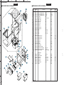
YST-MS30
YST-MS30
1
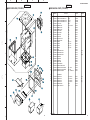
■ EXPLODED VIEW (YST-MS30)
■ MECHANICAL PARTS (YST-MS30)
4-8
Ref.
No.
✻ 1-1
✻ 1-1
✻ 1-2
✻ 1-2
✻ 2
3
✻ 4
✻ 4
✻ 4- 1
✻ 4- 1
✻ 4- 2
✻ 4- 2
✻ 4- 3
✻ 4- 3
✻ 4- 5
✻ 4- 6
✻ 4- 7
✻ 4- 8
✻ 4- 9
✻ 5- 1
✻ 5- 1
✻ 5- 1
✻ 5- 2
✻ 5- 3
✻ 5- 4
✻ 5- 5
✻ 5- 6
✻ 5- 7
✻ 5- 8
✻ 5- 9
5-10
4
4-2
4-7
2
3
4-5
4-1
3
4-3
4-6
4-9
4-6
5-8
5-10
5-7
5-4
4
2
5-10
5-3
(1)
✻
✻
✻
✻
5-9
Description
PART NO.
AAX12660 SATELLITE SPEAKER UNIT L
AAX12680 SATELLITE SPEAKER UNIT L
AAX12670 SATELLITE SPEAKER UNIT R
AAX12690 SATELLITE SPEAKER UNIT R
AAX09900 P.C.B ASS’Y
XW801A00 SPEAKER UNIT
AAX09790 CABINET ASS’Y
AAX09800 CABINET ASS’Y
AAX09660 GRILLE ASS’Y
AAX09670 GRILLE ASS’Y
AAX09830 TOP PLATE
AAX09840 TOP PLATE
AAX09680 BOTTOM PLATE
AAX09690 BOTTOM PLATE
AAX09590 SCREW
AAX09620 SCREW
AAX09610 SCREW
AAX09600 SCREW
AAX09770 FOOT
AAX09850 REAR PANEL ASS’Y
AAX09860 REAR PANEL ASS’Y
AAX09870 REAR PANEL ASS’Y
AAX09340 CUSHION A
AAX09350 CUSHION B
AAX09360 CUSHION C
AAX09720 MOLD CASE
AAX09370 CUSHION BUSH
AAX09700 KNOB VOLUME SUB-W
AAX09630 BIND HEAD B-TITE SCREW
AAX09640 BIND HEAD P-TITE SCREW
ED330086 BIND HEAD SCREW
V4609500
V4609800
V4609900
V4609700
VS104300
VS494400
ACCESSOIES
AC ADAPTOR
AC ADAPTOR
AC ADAPTOR
AC ADAPTOR
NONSKID PADS
CABLE, MINI PLUG
Remarks
WH (L)
BL (L)
WH (R)
BL (R)
AMP
12cm JA1286
WH
BL
WH
BL
WH
BL
WH
BL
3x10 Y P
3x12 B P
3x14 Y P
4x10 B P
3x8 BL B
3x10 BL
3x8 FCRM3-BL
054025L
054028L
054025R
054028R
057474
053939
055286
055293
054107
054108
053412
053413
053414
053415
018077
054162
054053
050315
055424
053458
054129
054130
053455
054083
054084
053456
084849
053508
075243
075321
075573
1.2A, DC15V
1.2A, DC15V
1.2A, DC15V
1.2A, DC15V
8pcs.
1.8m
054327
054329
054330
054328
011716
040878
Markets
(UC)
(A)
(BG)
(UC)
(B)
(G)
(A)
5-1
5-2
2
(2)
5-3
5-5
5
5-6
5-4
1-1
1-2
✻ New Parts
6
23
24
A
B
C
D
YST-MS30/YST-MS35D
YST-MS35D
YST-MS35D
1
■ EXPLODED VIEW (YST-MS35D)
■ MECHANICAL PARTS (YST-MS35D)
4-8
4
✻
✻
✻
✻
✻
4-2
✻
✻
✻
✻
✻
✻
✻
✻
✻
✻
✻
✻
✻
✻
✻
✻
✻
✻
✻
✻
✻
✻
✻
✻
4-7
2
3
4-5
4-1
3
4-3
4-6
4-9
4-6
5-8
5-7
5-4
4
5-10
2
5-10
5-3
(1)
✻
✻
✻
✻
5-9
2
(4)
5-1
✻
5-2
2
(2)
Ref.
No.
1-1
1-1
1-2
1-2
2
3
4
4
4- 1
4- 1
4- 2
4- 2
4- 3
4- 3
4- 5
4- 6
4- 7
4- 8
4- 9
5- 1
5- 1
5- 1
5- 2
5- 3
5- 4
5- 5
5- 6
5- 7
5- 8
5- 9
5-10
AAX12700 SATELLITE SPEAKER UNIT L
AAX12720 SATELLITE SPEAKER UNIT L
AAX12710 SATELLITE SPEAKER UNIT R
AAX12730 SATELLITE SPEAKER UNIT R
AAX09920 P.C.B. ASS'Y
XW801A00 SPEAKER UNIT
AAX09320 CABINET ASS'Y
AAX09330 CABINET ASS'Y
AAX09660 GRILLE ASS'Y
AAX09670 GRILLE ASS'Y
AAX09560 TOP PLATE
AAX09570 TOP PLATE
AAX09680 BOTTOM PLATE
AAX09690 BOTTOM PLATE
AAX09590 SCREW
AAX09620 SCREW
AAX09610 SCREW
AAX09600 SCREW
AAX09770 FOOT
AAX09730 REAR PANEL ASS’Y
AAX09750 REAR PANEL ASS’Y
AAX09760 REAR PANEL ASS’Y
AAX09340 CUSHION A
AAX09350 CUSHION B
AAX09360 CUSHION C
AAX09720 MOLD CASE
AAX09370 CUSHION BUSH
AAX09700 KNOB VOLUME SUB-W
AAX09630 BIND HEAD B-TITE SCREW
AAX09640 BIND HEAD P-TITE SCREW
ED330086 BIND HEAD SCREW
V4368200
VS494400
V4609500
V4609800
V4609900
V4609700
VS104300
V4612100
5-3
5-5
5-6
5
5-4
1-1
1-2
✻ New Parts
6
25
26
Description
PART NO.
ACCESSORIES
USB CABLE
CABLE, MINI PLUG
AC ADAPTOR
AC ADAPTOR
AC ADAPTOR
AC ADAPTOR
NONSKID PADS
CD ROM
Remarks
WH (L)
BL (L)
WH (R)
BL (R)
AMP
12cm JA1286
WH
BL
WH
BL
WH
BL
WH
BL
3x10 Y P
3x12 B P
3x14 Y P
4x10 B P
3x8 BL B
3x10 BL
3x8 FCRM3-BL
1P 2.0m
1.8m
1.2A, DC15V
1.2A, DC15V
1.2A, DC15V
1.2A, DC15V
8pcs.
054031L
054035L
054031R
054035R
057476
053939
055294
055295
054107
054108
054146
054147
053414
053415
018077
054162
054053
050315
055424
053460
054132
054133
053455
054083
054084
053456
084849
053508
075243
075321
075573
053019
040878
054327
054329
054330
054328
011716
054325
Markets
(UC)
(A)
(BG)
(UC)
(B)
(G)
(A)
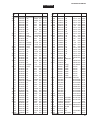
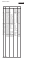
YST-MS30/YST-MS35D
Parts List for Carbon Resistors
Value
1.0 Ω
1.8 Ω
2.2 Ω
3.3 Ω
4.7 Ω
5.6 Ω
10 Ω
15 Ω
22 Ω
27 Ω
33 Ω
39 Ω
47 Ω
56 Ω
68 Ω
75 Ω
82 Ω
91 Ω
100 Ω
110 Ω
120 Ω
150 Ω
160 Ω
180 Ω
200 Ω
220 Ω
270 Ω
330 Ω
390 Ω
430 Ω
470 Ω
510 Ω
560 Ω
680 Ω
820 Ω
910 Ω
1.0 kΩ
1.2 kΩ
1.5 kΩ
1.8 kΩ
2.0 kΩ
2.2 kΩ
2.4 kΩ
2.7 kΩ
3.0 kΩ
3.3 kΩ
3.6 kΩ
3.9 kΩ
4.7 kΩ
5.1 kΩ
5.6 kΩ
6.8 kΩ
8.2 kΩ
9.1 kΩ
❊: Not available
1/4W Type Part No.
HJ35
HJ35
HJ35
HJ35
HJ35
HJ35
HF45
HJ35
HF45
HJ35
HF45
HJ35
HF45
HF45
HF45
HF45
HF45
HF45
HF45
HJ35
HF45
HF45
HJ35
HF45
HF45
HF45
HF45
HF45
HF45
HF45
HF45
HF45
HF45
HF45
HF45
HF45
HF45
HF45
HF45
HF45
HJ35
HF45
HJ35
HF45
HF45
HF45
HJ35
HF45
HF45
HF45
HF45
HF45
HF45
HF45
3100
3180
3220
3330
3470
3560
4100
4150
4220
4270
4330
4390
4470
4560
4680
4750
4820
4910
5100
5110
5120
5150
5160
5180
5200
5220
5270
5330
5390
5430
5470
5510
5560
5680
5820
5910
6100
6120
6150
6180
6200
6220
6240
6270
6300
6330
6360
6390
6470
6510
6560
6680
6820
6910
1/6W Type Part No.
Value
3100
❊
HF85 3220
HF85 3330
HF85 3470
HF85 3560
HF45 4100
HF85 4150
HF45 4220
HF85 4270
HF45 4330
HF85 4390
HF45 4470
HF45 4560
HF45 4680
HF45 4750
HF45 4820
HF45 4910
HF45 5100
HF85 5110
HF45 5120
HF45 5150
❊
HF45 5180
HF45 5200
HF45 5220
HF45 5270
HF45 5330
HF45 5390
HF45 5430
HF45 5470
HF45 5510
HF45 5560
HF45 5680
HF45 5820
HF45 5910
HF45 6100
HF45 6120
HF45 6150
HF45 6180
HF85 6200
HF45 6220
HF85 6240
HF45 6270
HF45 6300
HF45 6330
HF85 6360
HF45 6390
HF45 6470
HF45 6510
HF45 6560
HF45 6680
HF45 6820
HF45 6910
10 kΩ
11 kΩ
12 kΩ
13 kΩ
15 kΩ
18 kΩ
22 kΩ
24 kΩ
27 kΩ
30 kΩ
33 kΩ
36 kΩ
39 kΩ
47 kΩ
51 kΩ
56 kΩ
62 kΩ
68 kΩ
82 kΩ
91 kΩ
100 kΩ
110 kΩ
120 kΩ
150 kΩ
180 kΩ
220 kΩ
270 kΩ
300 kΩ
330 kΩ
390 kΩ
470 kΩ
560 kΩ
680 kΩ
820 kΩ
1.0 MΩ
1.2 MΩ
1.5 MΩ
1.8 MΩ
2.2 MΩ
3.3 MΩ
3.9 MΩ
4.7 MΩ
HF85
1/4W Type Part No.
7100
HF45 7110
HJ35 7120
HF45 7130
HF45 7150
HF45 7180
HF45 7220
HF45 7240
HJ35 7270
HF45 7300
HF45 7330
HF45 7360
HF45 7390
HF45 7470
HF45 7510
HF45 7560
HF45 7620
HF45 7680
HF45 7820
HF45 7910
HF45 8100
HF45 8110
HF45 8120
HF45 8150
HF45 8180
HJ35 8220
HF45 8270
HF45 8300
HF45 8330
HJ35 8390
HF45 8470
HJ35 8560
HJ35 8680
HJ35 8820
HF45 9100
HJ35 9120
HJ35 9150
HJ35 9180
HJ35 9220
HJ35 9330
HJ35 9390
HJ35 9470
HF45
1/6W Type Part No.
7100
7110
HF85 7120
HF45 7130
HF45 7150
HF45 7180
HF45 7220
HF45 7240
HF85 7270
HF45 7300
HF45 7330
HF45 7360
HF45 7390
HF45 7470
HF45 7510
HF45 7560
HF45 7620
HF45 7680
HF45 7820
HF45 7910
HF45 8100
HF45 8110
HF45 8120
HF45 8150
HF45 8180
HF85 8220
HF45 8270
HF45 8300
HF45 8330
HF85 8390
HF45 8470
HF85 8560
HF85 8680
HF85 8820
HF45 9100
❊
HF85 9150
HF85 9180
HF85 9220
HF85 9330
❊
HF85 9470
HF45
HF45
SERVICE MANUAL
1/4W Type
HF45
1/4W Type
HJ35
10mm
1/6W Type
HF85
5mm
1992
27
YST-MS30/MS35D