1
USER’S
M AN UAL AN D
P ROGRAM M IN G GUIDE
HDL-32E
High Definition LiDAR™ Sensor
i
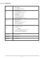
SAFETY NOTICES
1
INTRODUCTION
2
P R I N C I P L E S O F O P E R AT I O N
3
SETUP
5
USAGE
7
External GPS Time Synchronization
9
Packet Format and Status Byte
for GPS Time Stamping
9
9
10
Time Stamping Accuracy Rates
Laser Timing
Laser Firing Sequence
11
TROUBLESHOOTING
11
SERVICE AND MAINTENANCE
12
S P E C I F I C AT I O N S
13
APPENDIX A:
Digital Sensor Recorder (DSR)
16
APPENDIX B:
HDL-32E Sample Data Packets
22
APPENDIX C:
Coordinate Calculation Algorithm Sample Code
23
APPENDIX D:
Calibration and Orientation
24
APPENDIX E:
Ethernet Transit Timing Table
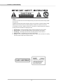
CAUTION — SAFETY NOTICE
Caution
To reduce the risk of electric shock and to avoid violating the warranty, do not open sensor body. Refer servicing to qualified
service personnel.
The lightning flash with arrowhead symbol is intended to alert the user to the presence of uninsulated “dangerous voltage”
within the product’s enclosure that may be of sufficient magnitude to constitute a risk of electric shock to persons.
The exclamation point symbol is intended to alert the user to the presence of important operating and maintenance
(servicing) instructions in the literature accompanying the product.
1.
2.
3.
4.
5.
Read Instructions — All safety and operating instructions should be read before the product is operated.
Retain Instructions — The safety and operating instructions should be retained for future reference.
Heed Warnings — All warnings on the product and in the operating instructions should be adhered to.
Follow Instructions — All operating and use instructions should be followed.
Servicing — The user should not attempt to service the product beyond what is described in the operating
instructions. All other servicing should be referred to Velodyne.
[i]
INTRODUCTION
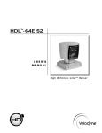
HDL-32E User’s ManuaI
Congratulations on your purchase of a Velodyne HDL-32E High Definition LiDAR Sensor. This sensor provides state-of-the-art 3D imaging.
This manual describes how to set up and operate the HDL-32E, covers installation and wiring, addresses output packet construction and
interpretation, along with GPS installation notes.
This manual is undergoing constant revision and improvement — check www.velodynelidar.com for updates.
[1]
P R I N C I P L E S O F O P E R AT I O N
HDL-32E User’s ManuaI
Principles of Operation
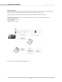
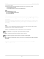
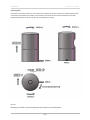
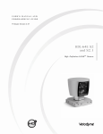
The HDL-32E creates 360° 3D images by using 32 laser/detector pairs whose housing rapidly spins to scan the surrounding environment.
This design allows for the lasers to each fire thousands of times per second, providing a rich, 3D point cloud.
Digital signal processing and waveform analysis provide high accuracy, extended distance sensing and intensity data.
The HDL-32E uses a direct drive motor system, employing no belts or chains in the drive train, to improve reliability and reduce
maintenance. The unit provides:
• A 360° horizontal field of view (FOV)
• A 41.3° vertical FOV
• Usable returns up to 70 meters
Figure 1. Overview of the LiDAR HDL-32E 3D Imaging System.
[2]
SETUP
HDL-32E User’s ManuaI
This section describes the standard set up assuming you are connecting the sensor to a standard computer or laptop and mounting the
sensor on a vehicle. For other connections and mounting locations, please contact Velodyne for technical assistance.
The standard setup involves:
1. Unpacking the shipping case contents.
2. Securely mounting the sensor base to a vehicle or other scanning platform.
3. Connecting power to the sensor.
4. Connecting the sensor’s data output to the computer.
Case Contents
The shipping case contains:
• HDL-32E sensor unit with approximately 3 meter cable terminated at an interface box.
• Desktop AC/DC power adapter.
• AC cord.
• 4.5 meter Ethernet cable.
• Garmin GPS-18LV GPS receiver with 5 meter cable.
• CD with:
- User manual. Check www.velodynelidar.com for updates.
- Calibration file (db.xml), sample data sets, DSR source code example and miscellaneous documents.
- DSR Viewer software
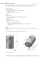
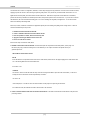
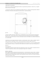
Mount Base
The sensor base provides mounting holes on the base. The sensor can be mounted at any angle from 0° to 360° with respect to the
sensor base.
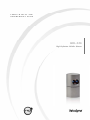
Refer to the figure below for location of the four 10-32 threaded, 3/8” deep mounting holes.
73.1
2.876
144.2
5.68
OVERALL HEIGHT
51.6
2.033
TWO .156 LOCATING FEATURES
FOR 5.32” DOWELL PINS
FOUR 10-32 THREADED
MOUNTING HOLES
3/8” DEEP
51.6
2.033
85.3
3.36
Figure 2: Sensor Base Mounting
[3]
INTERFACE CABLE
3 METERS LONG
SET UP
HDL-32E User’s Manual
Connect Power and Computer
The sensor units are commonly used in vehicle applications where standard 12 volt, 2 amp power is readily available.
1. Connect the interface module to power.
2. Connect the Ethernet connector to a standard PC or laptop RJ45 Ethernet port.
Operate
Before operating the sensor, make sure that:
• the sensor is in acceptable environmental conditions
• the sensor is securely mounted
Weather
The unit is weatherproofed to withstand wind, rain and other adverse weather conditions. The unit’s spinning motion helps it shed excess
water from the front window that could hamper performance. Refer to the specifications page for operational and storage temperature ranges.
Shock and Vibration
Be sure the unit is mounted securely to withstand vibration and shock without risk of detachment. The unit does not need shock proofing.
The unit is designed to withstand standard automotive G-forces; (500 m/sec2 amplitude, 11 msec duration shock and 3 Grms 5 Hz to
2000 Hz vibration).
Wiring
The HDL-32E comes with an integral cable that is terminated at an interface box. The cable is approximately 3 meters (10’) in length.
The interface box provides connections for Ethernet, power and GPS inputs.
Power. The 2.1 mm barrel plug jack fits the AC/DC power adapter included. The center pin is positive polarity.
Note: The HDL-32E does not have a power switch. It spins and operates whenever power is applied.
Ethernet. This standard RJ45 Ethernet connector is designed to connect to a standard PC.
Note: The HDL-32E is only compatible with network cards that have either MDI or AUTO MDIX capability.
GPS. The GPS connector fits the GPS receiver included. If you wish to wire your own GPS receiver, refer to the labeled connector within
the interface box.
Cable. The cable is permanently attached at the sensor but the interface box may be removed for ease of cable routing, direct
wiring and/or inserting in-line connector(s).
[4]
USAGE
HDL-32E User’s ManuaI
The HDL-32E sensor needs no configuration, calibration, or other setup to begin producing usable data. Once the unit is mounted and wired,
supplying it power will cause it to start scanning and producing data packets. The quickest way to watch the HDL-32E in action is to use
Digital Sensor Recorder (DSR), the viewer software included with the unit. DSR reads in the packets from the HDL-32E over Ethernet,
performs the necessary calculations to determine point locations, then plots the points in 3D on the viewer’s PC. If you have never used the
HDL-32E before, this is the recommended starting point. For more on installing and using DSR, see Appendix A. You can observe both
distance and intensity data through DSR.
Most users, however, will elect to create their own application-specific point cloud tracking and plotting and/or storage scheme. There are
several fundamental steps to this process:
1. Establish communication with the HDL-32E
2. Create a calibration table from the included db.xml data file
3. Parse the packets for rotation, distance and intensity data
4. Apply the vertical angle calibration factors to the data
5. Plot or store the data as needed
Each of these steps is described in detail, below.
1. Establish communication with the HDL-32E. The HDL-32E outputs two separate broadcast UDP packets. (refer to page 16 in
this manual). By using a network monitoring tool such as Wireshark you can capture and observe the packets as they are
generated by the unit.
HDL-32 MAC ID and IP address format:
Mac ID
Each HDL-32E has a unique MAC address based on the serial number, with the last four hex digits mapping to the serial number of the
unit. The following MAC ID shows serial number 4452:
60 76 88 20 11 64
IP Address
The Source IP address for the HDL-32E units maps to the last four digits in the Mac ID (and hence the serial number). In the above
example, the Source IP address would be represented by IP address:
192.168.17.100
In this example, the 11 and 64 are shown as decimal numbers for the purposes of expressing the IP address.
For all HDL-32E units, the destination IP address remains fixed at 192.168.3.255.
2. Create an internal calibration table from the included db.xml data file. This table must be built and stored internal to the point-cloud
processing software.
[5]
USAGE
HDL-32E User’s ManuaI
Alternatively, the calibration data can be found in the included db.xml file found on the CD included with the HDL-32E. The calibration data for
vertCorrection is the vertical correction angle for each laser, as viewed from the back of the unit and stated in degrees. Positive values have
the laser pointing up and negative values have the laser pointing down.
The calibration table, once assembled, will contain 64 instances of the calibration values to interpret the packet data to calculate each point’s
position in 3D space. Use only the first 32 instances.
3. Parse the packets for rotation, distance and intensity data. Each HDL-32E packet has a 1206 byte payload consisting of 12, 100
byte records followed by 6 bytes of GPS time stamp data. The zero degree position is 90 degrees to the right of the interface cable when
looking at the bottom.
Each 100 byte record contains first a start identifier, then a two byte rotational value, followed by 32 3-byte combinations that report on
each laser fired. Two bytes report distance to the nearest .2 cm, and the remaining byte reports intensity on a scale of 0 - 255.
There are 12 100 byte records. For more on packet construction, see Appendix B.
4. Apply the calibration factors to the data. Each of the HDL-32E’s lasers is fixed with respect to vertical angle. For each data point issued
by the sensor, vertical correction factors must be applied to determine the point’s location in 3D space referred to by the return.
Note: The minimum return distance for the HDL-32E is approximately 1 meter. Ignore returns closer than this.
Note: There is a file on the CD called “DSR Source Example” that shows the calculations using the above correction factors. This is the code
used in DSR to determine 3D locations of HDL-32E data points.
You may also want to store the data. If so, it may be useful to timestamp the data so it can be referenced and coordinated with other
sensor data later. The HDL-32E has the capability to synchronize its data with GPS precision time.
Note: There are no user service or maintenance procedures for the Velodyne HDL-32E. Velodyne does offer a preventative maintenance
service for a fee. For service or maintenance, please contact Velodyne at +1 (408) 465-2800, or log on to our website at
www.velodynelidar.com.
[6]
USAGE
HDL-32E User’s ManuaI
External GPS Time Synchronization
The HDL-32E can synchronize its data with precision GPS-supplied time pulses to enable users to ascertain the exact firing time of each laser
in any particular packet.
This capability requires a GPS receiver generating a sync pulse and the $GPRMC NMEA record over a dedicated RS-232 serial port.
The output from the GPS receiver is connected to the HDL-32E via the user interface box. The customer can use the GPS receiver
supplied with the HDL-32E or the customer can adapt their GPS receiver to provide the required sync pulse and NMEA record.
GPS Receiver Option 1: Velodyne Supplied GPS Receiver
A GPS receiver that is pre-programmed by Velodyne, is provided to HDL-32E users. This receiver is pre-wired with a connector that plugs
into the HDL-32E interface box, and pre-programmed to output the correct GPS record and sync pulse.
GPS Receiver Option 2: Customer’s GPS Receiver
Under this option the customer must configure their GPS device to issue a once-a-second synchronization pulse, typically output over a
dedicated wire, and issue a once-a-second $GPRMC NMEA record. No other output can be accepted from the GPS device. Further, the
sync pulse and NMEA record must be issued sequentially. The sync pulse length is not critical (typical lengths are between 20ms and
200ms), but the $GPRMC record must start between 50ms and 500ms after the end of the sync pulse.
Note: The $GPRMC record can be configured for either hhmmss format or hhmmss.s format.
Note: The connector within the supplied interface box can be used to interface the GPS receiver, or it can be wired directly as indicated
within the box.
[7]
USAGE
HDL-32E User’s ManuaI
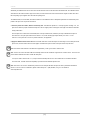
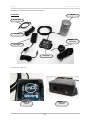
The images below show the GPS receiver included with the HDL-32E.
GPS EQUIPMENT
HDL-32E
Ethernet Cable
AC Cord
Garmin GPS-I8LV
GPS Receiver
Power Adapter
Interface Box
Interface Box Front & Back View
Interface Box
Top View
Interface Box
Front View
[8]
USAGE
HDL-32E User’s ManuaI
Packet Format and Status Byte for GPS Time Stamping
The 6 extra bytes at the end of the HDL-32E data packet are used to report GPS timing. For every packet, the last 6 bytes are formatted
as follows:
4 bytes: 32 bit unsigned integer time stamp. This value represents microseconds from the top of the hour to the first laser firing
in the packet.
2 bytes: blank
Time Stamping Accuracy Rules
The following rules and subsequent accuracy apply for GPS time stamping:
1. If the GPS isn’t connected (GPS Status 0), the HDL-32E starts running on its own clock starting at midnight Jan 1 2000. Expect
a drift of about 5 seconds per day under this method. This date and time data is reflected in the H, M, S, D, N, and Y data values.
Also note that the HDL-32E clock does not correct for leap years.
2. When the GPS is connected, the $GPRMC NMEA record is reported in the second data packet as described in Appendix B. GPS time
synching runs in one of two modes:
a. The GPS has an internal clock that runs for several weeks that will be used first. The accuracy is as good as the
GPS device employed.
b. When the GPS achieves lock, the HDL-32E clock will then be within +/-50ps of the correct time at all times.
3. If the GPS is then disconnected, the HDL-32E will continue to run on its own clock and be subject to a drift of approximately
5 seconds per day.
Laser Timing
If the GPS timestamp feature is employed, it may be useful to determine the exact firing time for each laser so as to properly time-align the
HDL-32E point cloud with other data sources.
The Ethernet packet is assembled in real time, therefore the encoder angle is associated with the first laser shot in each collection of
32 laser shots, while the time stamp is reported in the last 6 bytes of the packet relates to the last shot of the last group in the entire sequence
(of 12 records). The time stamp is synchronized to the leading edge of the GPS signal, as provided by the Garmin GPS-18LV GPS receiver
or the user’s GPS receiver programmed as described on page 7.
Lasers are fired on a clock running at 1.152 psec cycle time. There are 40 of these time periods per 32 firings with the dead time being used
to recharge the lasers, making the total time to fire all 32 lasers 46.08 psec. There are 12 of these 32-laser firing groups per packet, for a
total packet time of 552.96 psec. This totals to approximately 1808 packets per second, or approximately 694,292 laser shots per second.
A table can be found in Appendix E showing timing for each laser shot based on these calculations.
[9]
USAGE
HDL-32E User’s ManuaI
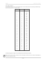
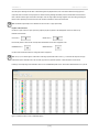
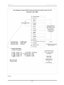
Laser Firing Sequence
The laser firing order is the same as the order in the Ethernet packet. The most downward laser fires first, followed by the interleaved firings
from the lower and upper “banks” of 16 lasers, as follows:
Firing order
DSR #
Vertical angle
1
0
-30.67
2
1
-9.33
3
2
-29.33
4
3
-8.00
5
4
-28.00
6
5
-6.66
7
6
-26.66
8
7
-5.33
9
8
-25.33
10
9
-4.00
11
10
-24.00
12
11
-2.67
13
12
-22.67
14
13
-1.33
15
14
-21.33
16
15
0.00
17
16
-20.00
18
17
1.33
19
18
-18.67
20
19
2.67
21
20
-17.33
22
21
4.00
23
22
-16.00
24
23
5.33
25
24
-14.67
26
25
6.67
27
26
-13.33
28
27
8.00
29
28
-12.00
30
29
9.33
31
30
-10.67
32
31
10.67
The interleaving firing pattern is designed to avoid potential ghosting caused primarily by retro-reflectors.
Note: Laser #9 from the top of the stack, or DSR #15, is set at a 0 vertical angle. This laser can be used as a reference to calibrate pitch and
yaw of the sensor relative to the vehicle.
[ 10 ]
TROUBLESHOOTING
HDL-32E User’s ManuaI
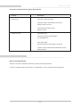
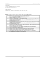
Use this chart to troubleshoot common problems with the HDL-32E.
Problem
Resolution
Unit doesn’t spin
Verify power connection and polarity.
Verify proper voltage — should be between 9 and 32 volts
drawing a minimum of one amp.
Inspect the fuse in the interface module.
Replace if necessary.
Unit spins but no data
Verify Ethernet wiring.
Verify packet output using another application
(e.g. EthereallWireshark).
Verify network settings.
Set a static IP address in network settings. 192.168.3.255.
Verify that no security software has been installed which may block
Ethernet broadcasts.
.
SERVICE AND MAINTENANCE
There are no user service or maintenance requirements or procedures for the Velodyne HDL-32E.
For service or maintenance, please contact Velodyne at +1 (408) 465-2800, or log on to our website at www.velodynelidar.com.
[ 11 ]
S P E C I F I C AT I O N S
Laser:
Sensor:
Mechanical:
Output:
HDL-32E User’s ManuaI
• Class 1 - eye safe
• 905 nm wavelength
• Time of flight distance measurement
• Measurement range 70 m (1 m to 70 m)
• 32 laser/detector pairs
• +10.67 to -30.67 degrees field of view (vertical)
• 360 degree field of view (horizontal)
• 10 Hz frame rate
• Operating temperature, -10° C to +60° C
• Storage temperature, - 40° to 105° C
• Accuracy: <2 cm (one sigma at 25 m)
• Angular resolution (vertical) ~1.33°
• Angular resolution (horizontal) ~0.16° at 600 rpm
• Power: 12V @ 2 Amps
• Operating voltage: 9-32 VDC
• Weight: <2 kg
• Shock: 500 m/sec2 amplitude, 11 msec duration
• Vibration: 5 Hz to 2000 Hz, 3 Grms
• Environmental Protection: IP67
• Approximately 700,000 points/second
• 100 Mbps Ethernet connection
• UDP packets
- distance
- rotation angle
• Orientation – internal MEMS accelerometers and gyros for
six-axis motion correction – external correction
• GPS time-synchronized with included GPS receiver
Dimensions:
(Height//Diameter)
• Unit: 5.68” x 3.36”
[149.86mm x 85.3mm]
Sensor Weight
• 2.9 lbs [ 1.3 Kg]
Shipping Weight:
(approx.)
• 14.35 lbs [ 6.5 Kg]
[ 12 ]
A P P E N D I X A : D I G I TA L S E N S O R R E C O R D E R ( D S R )
HDL-32E User’s ManuaI
Digital Sensor Recorder (DSR)
DSR is a windows-based 3D point cloud visualization software program designed for use with the HDL-32E. This software is an “out of the
box” tool for the rendering and recording of point cloud data from the HDL unit.
You can develop visualization software using the DSR as a reference platform. A code snippet is provided on the CD to aid in understanding
the methods at which DSR parses the data points generated by the HDL sensor.
Install
To install the DSR on your computer:
1. Locate the DSR executable program on the provided CD.
2. Double click on this DSR executable file to begin the installation onto the host computer. We recommend that you use of the
default settings during the installation.
Note: Refer to the “Read me” file on the supplied CD for Windows Vista and Windows 7 installations.
Calibrate
The db.xml file provided with the HDL unit contains correction factors for the proper alignment of the point cloud information gathered for
each laser. When implemented properly, the image viewable from the DSR is calibrated to provide an accurate visual representation of the
environment in which the sensor is being used. Also use these calibration factors and equations in any program using the data generated
by the unit.
Note: The HDL32E does not require additional calibration.
Live Playback:
For live playback, first secure and power up the HDL-32E sensor so that it is spinning. Connect the RJ45 Ethernet connector to your host
computer’s network connection. You may wish to utilize auto DNS settings for your computers network configuration.
DSR desktop icon =
Open DSR from your desktop icon created during the installation. Pull down the “Options” menu and select the proper input device.
Go to “Options” again and deselect the “Show Ground Plane” option. (Leave this feature off for the time being or until the ground
plane has been properly adjusted).
You can now go to “Options/Properties” to change the individual settings for each LASER channel if so desired.
REFRESH button =
Provided that your computer is now receiving data packets, click on the Refresh button to start live viewing of a point cloud. The initial image
is of a directly overhead perspective. See page 15 for mouse and key commands used to manipulate the 3D image within the viewer.
Note: The image can be manipulated in all directions and become disorienting. If you lose perspective, simply press F1 to return to the
original view.
Recording Data:
RECORD button =
[ 13 ]
APPENDIX A
HDL-32E User’s ManuaI
Once the input of streaming data has been confirmed through the live playback feature, click on the Record button and the program will
request the name and location for the pcap file to be created. Recording will begin immediately once the file information has been entered.
Click on the Record button again to discontinue the capture. One can string multiple recordings together on the same file by performing the
Record function repeatedly. A new file name will not be requested until after the session has been aborted.
Note: An Ethernet capture utility such as Wireshark can also be used as a pcap capture utility.
Playback of Recorded files:
Use the File › Open command to open a previously captured pcap file for playback. The DSR playback controls are similar to any
DVD/VCR control features.
PLAY button =
PAUSE button =
Press the Play button to render the file. The Play button will alternate to Pause when in playback mode.
FORWARD button =
REVERSE button =
Use the Forward and Reverse buttons to change the direction of playback.
Note: The X, Y, Z and distance figures at the bottom of the image represent the distance of the x, y, z crosshairs with respect to the origin
point indicated by the small white circle. The concentric gray circles and grid lines represent 10 meter increments from the sensor.
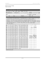
Following is an example image of the calibration values as seen in DSR/File/Properties screen. Values will be different than those on your CD.
Figure 3. Calibration values as seen in DSR/File/Properties
[ 14 ]
APPENDIX A
HDL-32E User’s ManuaI
DSR Key Controls
Zoom:
Z = Zoom in
Shift, Z = Zoom out
Z Axis Rotation:
Y = Rotate CW
Shift, Y = Rotate CCW
X Axis Rotation:
P = Rotate CW
Shift, P = Rotate CCW
Y Axis Rotation:
R = Rotate CW
Shift, R = Rotate CCW
Z Shift:
F = Forward
B = Back
X Shift:
L = Left
H = Right
Y Shift:
U = Up
D = Down
Aux. Functions:
Ctrl, (Z,Y,P,R,F,B,L,H,U,D) Direction = Fine Movement
Alt, (Z,Y,P,R,F,B,L,H,U,D) Direction = Very Fine Movement
DSR Mouse Controls
Rotational:
Left Button/Move
Slide:
Right Button/Move
Zoom:
Scroll forward = Zoom In
Scroll backward = Zoom Out
[ 15 ]
A P P E N D I X B : H D L - 3 2 E S A M P L E D ATA PA C K E T S
HDL-32E User’s ManuaI
Data Packet Format
The HDL-32E outputs two UDP Ethernet packets — a data packet containing laser firing data located on Port 2368 and a positioning packet
which contains GPS and positioning data located on Port 8308. The packet at Port 2368 contains a header, a data payload of firing data and
status data. Data packets are assembled with the collection of all firing data for twelve laser firing sequences. The laser distance and
intensity data is collected in the same staggered order (0, 16, 1, 17 . . . 14, 30, 15, 31) as the laser is firing. The data packet is then
combined with status and header data in a UDP packet transmitted over Ethernet. The firing data is assembled into the packets in the firing
order, with multi-byte values transmitted least significant byte first.
The status data always contains a GPS 4 byte timestamp representing milliseconds from the top of the hour. In addition, the status data
contains two reserved bytes not used at this time.
[ 16 ]
APPENDIX B
HDL-32E User’s ManuaI
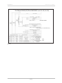
User Datagram Protocol (UDP) Ethernet Data Packet Format: HDL-32E (Port 2368)
Start identifier OxEEFF
2 mm increments (0 = no return within 100 m)
Blank
Blank
Figure B1.
[ 17 ]
APPENDIX B
HDL-32E User’s ManuaI
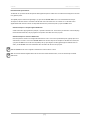
Positioning Packet
Using outputs from onboard gryrometers and 2-axis accelerometers, orientations shown below in Figure B2, the positioning ethernet Packet
provides motion data (rotational and acceleration) for the stationary base of the HDL-32E unit. See the User Datagram Protocol (UDP)
Positioning Ethernet Packet Format: HDL-32E, Figure B3, for interpretation of data output.
I
0 degrees
Figure B2.
Note: Each gyro incorporates a 2-axis accelerometer which results in redundancy in some axial directions.
[ 18 ]
APPENDIX B
HDL-32E User’s ManuaI
234
Figure B3.
[ 19 ]
APPENDIX B
HDL-32E User’s ManuaI
Time Stamp:
“7c bd 9c 91” 2442968444(919cbd7c hex)usec = 2442.9sec
Time stamp from the head of the hour in usec.
NMEA Sentence:
“$GPRMC, 214042, A, 3708.3087, N, 12139.5146W, 000.0, 000.0, 160311, 014.8, E, A 0C”
[ 20 ]
APPENDIX B
HDL-32E User’s ManuaI
Ethernet Packet Example
Captured via Wireshark.
[ 21 ]
A P P E N D I X C : C O O R D I N AT E C A L C U L AT I O N A L G O R I T H M S A M P L E C O D E
HDL-32E User’s ManuaI
Coordinate Calculation Algorithm Sample Code
After removing all the correction parameters except vertical correction,
the calculation code is:
firingData::computeCoords(guintl6 laserNum, boost::shared_ptr<CalibrationDB> db,
GLpos_t &pos)
{
guintl6 idx = laserNum % VLS_LASER_PER_FIRING;
boost::shared_ptr<CalibrationPoint> cal = db->getCalibration(laserNum);
if (data->points[idx].distance == O) {
coords[idx].setX(O.O);
coords[idx].setY(O.O);
coords[idx].setZ(O.O);
return;
}
float distance = db->getDistLSB() * (float)data->points[idx].distance;
II Get measured distance, distancel
float cosVertAngle = cal->getCosVertCorrection();
float sinVertAngle = cal->getSinVertCorrection();
float cosRotAngle = rotCosTable[data->position];
float sinRotAngle = rotSinTable[data->position];
float xyDistance = distance * cosVertAngle; II Convert to X-Y plane
coords[idx].setX(xyDistance * sinRotAngle + pos.getX()IVLS_DIM_SCALE);
II Calculate X coordinate
coords[idx].setY(xyDistance * cosRotAngle + pos.getY()IVLS_DIM_SCALE);
II Calculate Y coordinate
IICalculate Z coordinate
coords[idx].setZ(distance * sinVertAngle + pos.getZ()IVLS_DIM_SCALE);
}
[ 22 ]
A P P E N D I X D : C A L I B R AT I O N A N D O R I E N TAT I O N
HDL-32E User’s ManuaI
Calibration and Orientation
There are six axes of variation when determining the exact location of any given laser firing for the HDL-32. The axes are x, y, z, along with
rotational, horizontal, and vertical angles.
X, Y, Z. Both x and y offsets are zero and are calculated from the centerline of the device. The Z location of the firing should be considered to
be the distance from the bottom of the base plane to the center of the lenses, or 3.575 inches (9.0805 cm).
Figure Dl.
The device isn’t calibrated at the factory for angular accuracy. The angular precision is 1/100 of a degree, and the device should repeat to
this level of accuracy. There are provisions for a pair of dowel pins to be located in the mating fixture, and this will provide repeatability in
case the device is removed and remounted. The reason for this is that the device needs to be calibrated in situ to whatever defines either the
x or y axis of the vehicle.
The HDL-32E’s laser spots are aligned at the factory to be within 1/2” of their true position at 100 feet. Therefore, no calibration of either the
deflection (horizontal) or rotational angle is necessary — both the horizontal angle and rotational laser angles are always zero.
The vertical angle of each laser is described in the XML file supplied with each unit and as listed above. This is the only calibration parameter
necessary to plot points in 3D space, so for the HDL-32E all db.xml calibration files are identical and contain only the vertical angle values as
listed above.
Laser Spot Size
The lasers project a well defined rectangular shaped spot that is approximately 4” wide by 2” tall at 100’ distance. The spot size at the source
of the HDL-32 is approximately 1/2” wide by 1/4” tall, causing the angular divergence to be 2.79 milliradians.
Distance Calibration
Distance calibration parameters are programmed into the HDL-32E firmware — no external adjustment for distance is needed. The HDL-32E
uses ((1023/1024) * 300,000,000 meters/sec) as the reference speed of light. However, as the true speed is affected by local atmospheric
conditions, the unit uses a closed-loop timing compensation scheme that calibrates each laser continuously and is the primary compensation
for thermally induced timing corrections.
[ 23 ]
A P P E N D I X D : C A L I B R AT I O N A N D O R I E N TAT I O N
HDL-32E User’s ManuaI
[ 24 ]
Velodyne LiDAR, Inc.
345 Digital Drive
Morgan Hill, CA 95037
408.465.2800 voice
408.779.9227 fax
408.779.9208 service fax
www.velodynelidar.com
Service Email: [email protected]
Sales Email: [email protected]
All Velodyne products are made in the U.S.A.
Specifications subject to change without notice
Other trademarks or registered trademarks are property of their respective owner.
63-9113 Rev C F e b 2 0 1 2