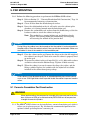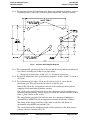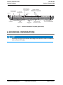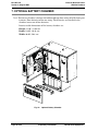
1
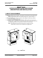
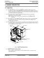
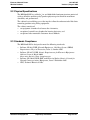
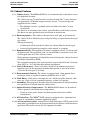
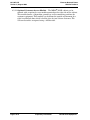
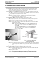
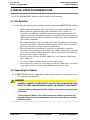
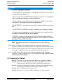
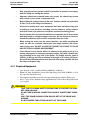
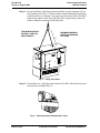
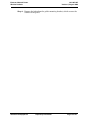
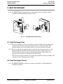
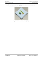
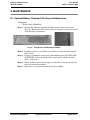
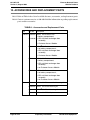
MESA® SOLE Outdoor
Electronic Enclosure
Description and Installation
Part Number 631-205-105
Version C, August 2009
Copyright 2009, Emerson Network Power, Energy Systems, North America, Inc. All rights
reserved. Any unauthorized reproduction or transmission without the prior consent of
Emerson Network Power, Energy Systems, North America, Inc. is prohibited.
This document is the property of Emerson Network Power, Energy Systems, North
America, Inc. and contains confidential and proprietary information owned by Emerson
Network Power, Energy Systems, North America, Inc. Any copying, use or disclosure of it
without the written permission of Emerson Network Power, Energy Systems, North
America, Inc. is strictly prohibited.
Emerson Network Power
Wireline Products
631-205-105
Version B, March 2009
Table of Contents
1. ABOUT THIS DOCUMENT
1
2. CABINET DESCRIPTION
2
2.1
Application . . . . . . . . . . . . . . . . . . . . . . . . . . . . . . . . . . . . . . . . . . . . . . . . . . . . . . . . . . . .
2
2.2
Physical Specifications . . . . . . . . . . . . . . . . . . . . . . . . . . . . . . . . . . . . . . . . . . . . . . . . . .
3
2.3
Standards Compliance . . . . . . . . . . . . . . . . . . . . . . . . . . . . . . . . . . . . . . . . . . . . . . . . . .
3
2.4
Cabinet Dimensions . . . . . . . . . . . . . . . . . . . . . . . . . . . . . . . . . . . . . . . . . . . . . . . . . . . . .
4
2.5
Cabinet Features . . . . . . . . . . . . . . . . . . . . . . . . . . . . . . . . . . . . . . . . . . . . . . . . . . . . . . .
5
3. OPENING AND CLOSING DOORS
7
4. INSTALLATION CONSIDERATIONS
8
4.1
Site Selection . . . . . . . . . . . . . . . . . . . . . . . . . . . . . . . . . . . . . . . . . . . . . . . . . . . . . . . . . .
8
4.2
Unpacking the Cabinet . . . . . . . . . . . . . . . . . . . . . . . . . . . . . . . . . . . . . . . . . . . . . . . . . .
8
4.3
Preparing the Cabinet . . . . . . . . . . . . . . . . . . . . . . . . . . . . . . . . . . . . . . . . . . . . . . . . . . .
9
4.4
Lifting the Cabinet . . . . . . . . . . . . . . . . . . . . . . . . . . . . . . . . . . . . . . . . . . . . . . . . . . . . . .
10
5. PAD MOUNTING
14
5.1
14
Concrete Foundation Pad Construction . . . . . . . . . . . . . . . . . . . . . . . . . . . . . . . . . . . . .
6. GROUNDING CONSIDERATIONS
17
7. OPTIONAL BATTERY CHAMBER
18
8. HEAT EXCHANGER
19
8.1
Heat Exchanger Fans . . . . . . . . . . . . . . . . . . . . . . . . . . . . . . . . . . . . . . . . . . . . . . . . . . .
19
8.2
Heat Exchanger Control . . . . . . . . . . . . . . . . . . . . . . . . . . . . . . . . . . . . . . . . . . . . . . . . .
19
9. MAINTENANCE
21
9.1
21
Optional Battery Chamber Filter Screen Maintenance . . . . . . . . . . . . . . . . . . . . . . . . . .
Outside Plant Equipment
Proprietary Information
Page i of ii
631-205-105
Version B, March 2009
Emerson Network Power
Wireline Products
10. ACCESSORIES AND REPLACEMENT PARTS
Page ii of ii
Proprietary Information
22
Outside Plant Equipment
Emerson Network Power
Wireline Products
631-205-105
Version B, March 2009
List of Figures
Fig. 1
MESA® SOLE . . . . . . . . . . . . . . . . . . . . . . . . . . . . . . . . . . . . . . . . . . . . . . . . . . . . .
1
Fig. 2
MESA® SOLE Exploded View . . . . . . . . . . . . . . . . . . . . . . . . . . . . . . . . . . . . . . . . .
2
Fig. 3
MESA® SOLE Dimensions . . . . . . . . . . . . . . . . . . . . . . . . . . . . . . . . . . . . . . . . . . .
4
Fig. 4
1/ -turn
4
security bolt . . . . . . . . . . . . . . . . . . . . . . . . . . . . . . . . . . . . . . . . . . . . . . . .
7
Fig. 5
Lifting Up on Slotted Bar to Release Wind Latch . . . . . . . . . . . . . . . . . . . . . . . . . .
7
Fig. 6
Gasket Placement . . . . . . . . . . . . . . . . . . . . . . . . . . . . . . . . . . . . . . . . . . . . . . . . . .
10
Fig. 7
Lifting the Cabinet . . . . . . . . . . . . . . . . . . . . . . . . . . . . . . . . . . . . . . . . . . . . . . . . . .
12
Fig. 8
Removing Battery Chamber Base Panel . . . . . . . . . . . . . . . . . . . . . . . . . . . . . . . . .
12
Fig. 9
Concrete Pad Template Diagram . . . . . . . . . . . . . . . . . . . . . . . . . . . . . . . . . . . . . .
15
Fig. 10
Foundation Pad Design with Customer Conduit Location . . . . . . . . . . . . . . . . . . .
16
Fig. 11
Position of Conduit in Template (typical view) . . . . . . . . . . . . . . . . . . . . . . . . . . . .
17
Fig. 12
Optional Battery Chamber . . . . . . . . . . . . . . . . . . . . . . . . . . . . . . . . . . . . . . . . . . .
18
Fig. 13
Door Mounted Heat Exchanger . . . . . . . . . . . . . . . . . . . . . . . . . . . . . . . . . . . . . . .
19
Fig. 14
Environmental Control Card (ECC) . . . . . . . . . . . . . . . . . . . . . . . . . . . . . . . . . . . . .
20
Fig. 15
Filter Screen and Mounting Hardware . . . . . . . . . . . . . . . . . . . . . . . . . . . . . . . . . .
21
Outside Plant Equipment
Proprietary Information
Page i of i
Emerson Network Power
Wireline Products
631-205-105
Version C, August 2009
MESA® SOLE
OUTDOOR ELECTRONIC ENCLOSURE
DESCRIPTION AND INSTALLATION
1. ABOUT THIS DOCUMENT
1.1 Purpose - This practice provides a description and installation instructions for the
MESA® SOLE (Modular Electronic Sealed Architecture) cabinet. See Fig. 1.
1.2 Reason For Reissue - Practice revised to add additional clarification to Fig. 9,
Concrete Pad Template Diagram.
1.3 Information Not Provided in this Practice - Refer to other local practices or
building codes as applicable for the correct methods, tools and materials to be used
in performing procedures not specifically described in this document.
Note: The information contained in this practice is subject to change
without notice and may not be suitable for all applications.
Fig. 1 : MESA® SOLE
Outside Plant Equipment
Proprietary Information
Page 1 of 23
631-205-105
Version C, August 2009
Emerson Network Power
Wireline Products
2. CABINET DESCRIPTION
2.1 Application
2.1.1 The MESA® SOLE is part of the MESA® line of Modular Electronic Sealed
Architecture cabinets. The MESA® SOLE cabinet provides a flexible, economical
housing within the network infrastructure. The cabinet is deployed in limited size
and remote outside plant applications.
2.1.2 The cabinets offer a compact solution for housing electronics, protection,
distribution, and battery backup.
Note: All power and alarm cables are provided with the MESA® SOLE
enclosures.
2.1.3 The compact size of the MESA® SOLE allows it to be wall, pad, or pole mounted.
For applications where the cabinet is to be pad mounted, the optional base
chamber must be ordered.
2.1.4 The MESA® SOLE cabinet provides a sealed internal environment where outside
air and humidity are totally isolated from the electronic equipment. Refer to Fig. 2
for an exploded view of the cabinet.
Equipment
Chamber
Solar Shield
Customer Access
Module
Battery Compartment
(Optional)
Access Panel
Fig. 2 : MESA® SOLE Exploded View
2.1.5 MESA® SOLE Ordering Guide:
Refer to Table A on page 22 for a list of available features, accessories, and
replacement parts.
Page 2 of 23
Proprietary Information
Outside Plant Equipment
Emerson Network Power
Wireline Products
631-205-105
Version C, August 2009
2.2 Physical Specifications
The MESA® SOLE is a welded 1/8-in. and .090 thick aluminum structure protected
with an off-white multistage dry powder polyester paint finish for maximum
durability and performance.
The cabinet has two lifting eyes at the top that allow the enclosure to be lifted into
mounting position using lifting equipment.
The cabinet consists of:
•
•
•
an equipment chamber that houses the electronics,
an optional vented base chamber for housing batteries, and
an optional side mountable Customer Access Module.
2.3 Standards Compliance
The MESA® SOLE is designed to meet the following standards:
•
•
•
•
Bellcore, GR-63-CORE, Network Equipment - Building System (NEBS)
Requirements: Physical Protection, Issue 1, October 1995.
Bellcore, GR-487-CORE, Generic Requirements for Electronic Equipment
Cabinets, Issue 2, March 2000.
Stem meets Seismic, Zone 4 requirements.
Bellcore, GR-1089-CORE, EMC and Electrical Safety Generic Criteria for
Network Communications Equipment, Issue 1 November 1997.
NEC, National Electrical Code.
Outside Plant Equipment
Proprietary Information
Page 3 of 23
631-205-105
Version C, August 2009
Emerson Network Power
Wireline Products
2.4 Cabinet Dimensions
Height:
•
•
•
Without battery base: 33.02" (83.87 cm)
Battery base for 60 Amp hr. batteries: 14.98" (38.05 cm)
Total height with battery base installed: 48.00" (121.92 cm)
Depth: 26.53" (67.39 cm)
Width: 33.13" (84.14 cm without Customer Access Module)
43.13" (109.80 cm with Customer Access Module)
Weight of Cabinet with Customer Access Module and Battery Base:
•
Empty cabinet approximately 309 lbs. (140.16 kg).
— For equipment add approximately 125 lbs. (56.70 kg).
— For batteries (60Ahr) add approximately 200 lbs. (90.72 kg).
Fig. 3 : MESA® SOLE Dimensions
Page 4 of 23
Proprietary Information
Outside Plant Equipment
Emerson Network Power
Wireline Products
631-205-105
Version C, August 2009
2.5 Cabinet Features
2.5.1 Cabinet Access - The MESA® SOLE has an environmentally sealed door to access
the equipment chamber.
The cabinet has two 1/4-turn fasteners securing the door. The 1/4-turn fasteners
are opened with a T-Handle tamper-resistant wrench, 5/16-inch hex/pin tool
supplied with the cabinet.
•
For additional security, a padlock can be installed on the lower 1/4-turn
security bolt.
The door has an intrusion alarm switch, and self-locking wind latches to secure
the door in the open position during installation or maintenance.
2.5.2 Mounting options - The cabinet is designed to be wall, pole, or pad mounted.
The cabinet shall be lifted into place using the lifting eyes provided on the top of
the cabinet.
When pad mounting,
•
•
A rubber pad will be provided to isolate the cabinet from the concrete pad.
A universal pad-mounting template can be ordered as an option.
2.5.3 Equipment Rails - The equipment chamber is equipped with 23" (58.42 cm) wide
equipment rails. The equipment rails are zinc-dichromate conductive steel with
12-24 tapped holes on 1 inch (2.54 cm) centers.
Each equipment mounting rail is bonded by contact through the cabinet chassis to
the Master Ground Bar (MGB).
The equipment mounting rails are designed to accept standard 12 inch (30.48 cm)
deep with 5-in. (12.7 cm) front offset mounted equipment.
2.5.4 Vertical Rack space - There is 25 inches (63.50 cm) of unobstructed vertical
mounting space in the equipment chamber door opening. A total of 28 inches
(71.12 cm) of rack space is available.
2.5.5 Environmental Control - The cabinet is equipped with a door mounted heat
exchanger, which is capable of removing 650 Watts of heat at 65o.
2.5.6 Cable Entry - Cable entry is through one 4-in. (10.16 cm) inside diameter cable
cone, one 1-inch (2.54 cm) grommeted opening, and one 3/4" opening.
2.5.7 Grounding - The equipment chamber contains two 6-position, 2-hole ground bars.
One ground bar is isolated from the cabinet frame.
2.5.8 Optional Battery Compartment - The MESA® SOLE cabinet can be ordered
with an optional ventilated battery compartment.
•
A battery heater pad is factory installed to protect batteries in colder
environments.
2.5.9 AC Power Box - The MESA® SOLE cabinet is equipped with a 2-position load
center to accommodate customer-supplied AC power.
2.5.10 AC Convenience Outlet - Ground Circuit Fault Interrupter (GFCI) protected 15
Amp outlet is provided for use by field personnel for installation and maintenance
operations. The outlet is located in the equipment chamber.
Outside Plant Equipment
Proprietary Information
Page 5 of 23
631-205-105
Version C, August 2009
Emerson Network Power
Wireline Products
2.5.11 Optional Customer Access Module - The MESA® SOLE cabinet can be
ordered with an optional access module mounted on the right side of the cabinet.
This module houses a 10-position ground bar and has mounting positions for
customer equipment. This module is sealed from the outside environment by a
right-hand hinged door, which is held in place by two 1/4-turn fasteners. The
1/4-turn fasteners are opened using a 216 hex tool.
Page 6 of 23
Proprietary Information
Outside Plant Equipment
Emerson Network Power
Wireline Products
631-205-105
Version C, August 2009
3. OPENING AND CLOSING DOORS
3.0.1 Purpose - This section describes the locking mechanisms on the doors of the
cabinet and explains how to open and close the doors. Refer to this section
whenever instructed to open or close cabinet doors.
3.0.2 Lock Type - The MESA® SOLE cabinet has two 1/4-turn fasteners securing the
door. The 1/4-turn fasteners are opened with a T-Handle tamper-resistant wrench,
5/ -inch hex/pin tool supplied with the cabinet.
16
Note: For additional security, a padlock can be installed on the bottom
1
/4-turn security bolt. (shown in Fig. 4).
3.0.3 Opening a Door - Perform the following steps to open a door:
Step 1: If required, use a key to unlock the door according to local practices.
Step 2: Place the tamper-resistant wrench onto a security bolt.
Step 3: Rotate the wrench one-quarter turn (90 degrees) to toward the top or
bottom of the cabinet.
Note: A 1/4 turn is LEFT HAND if it is on the LH SIDE of the door.
To close the 1/4 turn, rotation is to the LEFT. The hinge is to
the RIGHT.
A 1/4 turn is RIGHT HAND if it is on the RH SIDE of the
door. To close the 1/4 turn, rotation is to the RIGHT. The
hinge is to the LEFT.
Wind Latch
Cabinet Door
Equipment
Chamber
Fig. 4 : 1/4-turn security bolt
Fig. 5 : Lifting Up on Slotted Bar
to Release Wind Latch
Step 4: As each door is opened, secure the wind latch (Fig. 5) by opening the door
wide enough so the shoulder engages the hole and slot at the end of the
bar.
3.0.4 To close a door - Perform the following steps to close a door:
Step 1: Lift the slotted bar on the wind latch to release the shoulder from the
hole and slot. (See Fig. 5.).
Step 2: Close the door.
Step 3: While holding the door closed, rotate each 1/4-turn security bolt
one-quarter turn (90 degrees) toward top or bottom of the cabinet.
Outside Plant Equipment
Proprietary Information
Page 7 of 23
631-205-105
Version C, August 2009
Emerson Network Power
Wireline Products
4. INSTALLATION CONSIDERATIONS
4.0.1 The MESA® SOLE cabinet can be wall, pole, or pad mounted.
4.1 Site Selection
4.1.1 Consider the following when deciding on the location for the MESA® SOLE cabinet:
•
•
•
•
•
•
Before construction begins, obtain the rights-of-way from landowners, and
other permits or approvals from public authorities. Place cabinets in
servitudes, on dedicated (recorded) easements, or on property owned by the
company. Avoid any unrecorded easements. Use public safety road and street
rights-of-way only when there is enough space to place the closure and provide
safe working conditions.
The cabinet should be easily accessible with adequate parking to ensure safety
for people and vehicles. Place the cabinet where it will not create a visual or
physical obstruction to either vehicles or pedestrians.
Select locations that will minimize accidental or intentional vandalism.
Consider the use of protective posts when the cabinet is located near parking
areas where vehicles could back into the cabinet. Do not place the cabinet in
ditches or areas subject to flooding.
Place the cabinet at least 42 inches (106.68 cm) away from any obstruction,
fence, hedge, etc.
If an area is subject to frost, choose a site free of heaving.
Always locate the cabinet on a site above the 100-year flood plain, and which
is not subject to water runoff or flash flooding during heavy rains.
4.2 Unpacking the Cabinet
4.2.1 MESA® SOLE cabinet is shipped on wooden pallets with plastic covering to protect
the cabinet during shipment.
DANGER
DANGER: A CABINET NOT SECURED TO A PALLET OR PAD IS UNSTABLE AND
COULD TIP OVER CAUSING SERIOUS INJURY OR DAMAGE TO EQUIPMENT.
* Do not install any equipment until the cabinet is secured to its concrete foundation pad.
* Do not open any doors on the cabinet unless the cabinet is secured to the
shipping pallet or concrete foundation pad. An unsecured cabinet is unstable
and may tip over.
Page 8 of 23
Proprietary Information
Outside Plant Equipment
Emerson Network Power
Wireline Products
631-205-105
Version C, August 2009
ALERT
TO AVOID EQUIPMENT DAMAGE:
* DO NOT REMOVE - pallet and plastic covering from the cabinet until the cabinet is
transported to the installation site.
* Always ship and store the MESA® SOLE cabinet(s) on the pallet in an upright position to avoid possible damage to the internal equipment.
* Until the cabinet is turned up for service, the desiccant shipped with the cabinet
must remain in the cabinet to retard moisture condensation.
* DO NOT REMOVE - battery drawer covers until the cabinet is bolted securely to the
pad.
* DO NOT INSTALL OR STORE - batteries in cabinet(s) prior to cabinet installation.
* If the external packaging appears excessively damaged, do not accept the unit from
the shipper as interior damage may not be apparent.
* CAREFULLY remove all packaging material from around the cabinet and pallet.
Dispose of the packaging according to local practices. DO NOT REMOVE THE CABINET FROM ITS PALLET AT THIS TIME.
Note: When ordered, batteries are shipped on separate pallets from the
cabinet.
4.2.2 Inspect any moving parts, mounting hardware, connectors, and electronic
equipment. If there is any damage, notify your supervisor for further instructions.
4.2.3 Check the packing slip to make sure all components ordered were received. If there
are missing components, notify your supervisor for further instructions.
4.2.4 Carefully remove all packaging material from around the pallet. Dispose of
packaging according to local practices. DO NOT REMOVE THE CABINET FROM
ITS PALLET AT THIS TIME.
4.3 Preparing the Cabinet
Step 1: If not done already, open the front door of the equipment chamber.
Step 2: Remove the mounting bolts from the front equipment base cover and
remove the cover. Set the cover safely aside for later replacement.
Step 3: A gasket is installed on the concrete pad to prevent corrosion between
the concrete pad and the cabinet mounting surfaces (Fig. 6).
Step 4: Clean all debris from the concrete pad.
Step 5: Remove the rectangular rubber gasket from the splice chamber.
Outside Plant Equipment
Proprietary Information
Page 9 of 23
631-205-105
Version C, August 2009
Emerson Network Power
Wireline Products
Step 6: Place the gasket into position on the foundation pad so that the gasket
will lie underneath the bottom of the cabinet when it is placed. The
gasket should lie so the cutouts are in position around the conduit
openings, and over the anchor bolts.
Step 7: The front chamber door must stay open and the wind latch secured.
OSP
CABLE
ENTRY
Fig. 6 : Gasket Placement
Step 8: Remove the cable cone from the cabinet floor by removing the 1/4"
hardware. Remove and set the cable cone safely aside for later
reattachment.
Step 9: If the cabinet will be equipped with cables from a remote location,
remove the cable cone from the cable sleeves in the protection chamber.
Set the cable cone safely aside for later reattachment.
4.4 Lifting the Cabinet
DANGER
Improper hoisting equipment and unsafe lifting procedures can result in serious
injury or death.
•
Observe the following safety measures, as well as all local safety procedures, when performing the tasks in this section.
•
Keep the equipment and the cabinet away from any power lines.
•
Keep bystanders away from work operations at all times.
Page 10 of 23
Proprietary Information
Outside Plant Equipment
Emerson Network Power
Wireline Products
631-205-105
Version C, August 2009
•
Only specially trained operators shall be permitted to operate crane equipment for lifting and setting the cabinet.
•
Operators should not suspend loads over people, nor should any person
work, stand, or pass under a suspended load.
•
Before lifting the cabinet, block off the area. Vehicles should not park within
25 feet (7.6 m) of the lifting circumference.
•
All persons working with crane equipment shall wear standard safety gear
according to local practices, including, but not limited to, safety helmets,
steel-toed shoes, eye protection, and (when required) insulating gloves.
•
Do not operate the crane until all stabilizers are extended and in firm contact
with the ground or adequate support structure. Do not attempt to retract or
extend the stabilizers while a load is suspended from the crane.
•
When raising the crane from the stowed position, and while operating the
crane, be alert for overhead obstructions that might interfere with movement of the crane. DO NOT ALLOW THE CABINET OR CRANE TO TOUCH
ANY ELECTRICAL WIRING OR EQUIPMENT!
•
If the cabinet is to be moved while it is attached to the pallet (such as in a
turnkey staging area or temporary storage location), lift it with a forklift vehicle positioned at the long side of the pallet. The forklift must be rated at
5,000 lb. (2,268 kg) and have a minimum fork length of 50 inches (1270 mm).
Do not lift the pallet and cabinet from the ends when using a forklift; lift from
the sides of the pallet only.
4.4.1 Required Equipment
•
•
•
•
One derrick (crane) capable of lifting 5,000 lbs. (2,268 kg.).
Two, 8-ft. long (minimum) (2.4 m) wire rope slings, each with 2,500 lbs. (1,134
kg) capacity should be used.
Two connecting links to attach wire rope slings to the cabinet lifting ears.
0.63" (5/8-in) (4 cm) diameter rope, approximately 75 feet (19 m) long to be used
as a tagline.
WARNING
TAKE THE FOLLOWING SAFETY PRECAUTIONS TO PREVENT THE CABINET FROM FALLING:
DO NOT USE SLINGS OR CONNECTING LINKS OF INSUFFICIENT CAPACITY.
ONLY THE CRANE RIGGING CREW SHOULD SET UP THE CRANE AND
RIGGING.
DO NOT EXCEED THE LIFTING CAPACITY OF THE CRANE.
Outside Plant Equipment
Proprietary Information
Page 11 of 23
631-205-105
Version C, August 2009
Emerson Network Power
Wireline Products
Step 1: Insert the lifting cable sling connecting links securely through each of
the two lifting ears (Fig. 7). To prevent the cabinet from tipping when the
pallet brackets are removed, take up the slack with the crane. DO NOT
tighten the cables so that the pallet lifts. The weight of the pallet will
make it difficult to remove the bracket bolt.
TWO SLINGS SHOULD
BE USED - ONE FOR
EACH EYEBOLT.
MINIMUM REQUIRED
LENGTH OF SLINGS IS
8 FT (2.4M).
Fig. 7 : Lifting the Cabinet
Step 2: If installed, use a 216-type tool to remove the OSP cable side base panel
of the battery chamber (Fig. 8).
Fig. 8 : Removing Battery Chamber Base Panel
Page 12 of 23
Proprietary Information
Outside Plant Equipment
Emerson Network Power
Wireline Products
631-205-105
Version C, August 2009
Step 3: Remove the bolts from the pallet mounting bracket, which secures the
cabinet to the pallet.
Outside Plant Equipment
Proprietary Information
Page 13 of 23
631-205-105
Version C, August 2009
Emerson Network Power
Wireline Products
5. PAD MOUNTING
5.0.1 Perform the following procedure to pad mount the MESA® SOLE cabinet.
Step 1: Refer to Section 5.1 , "Concrete Foundation Pad Construction," Page 14
for recommended concrete pad construction.
Step 2: Clean all litter from the foundation pad surface.
Step 3: Dress the cable/conduit so that it will easily enter the cabinet splice
chamber as it is being lowered onto the foundation pad.
Step 4: Remove the anchor bolts and washers from the foundation pad. Set the
hardware aside to attach the cabinet to the pad.
Note: The conduit has a turning locking nut and bushing already
in place. The turning locking nut and bushing aid in aligning
and securing the conduit to the junction box.
ALERT
During lifting, the cabinet must be lowered so that the cabinet is level and parallel to
the pad surface. Place the cabinet so that it lines up with the anchor bolts. Make sure
the cabinet is clear of the conduits in the foundation pad.
Step 5: Place the cabinet on the pad. Loosen the slings so that the full weight of
the cabinet is on the pad. Check to be sure the cabinet is properly lined
up on the pad.
Step 6: To secure the cabinet to the pad, install 0.5-13 (1/2-13) bolts with washers
and lock washers into the bottom flange. Tighten all bolts securely.
Step 7: When the cabinet is secured, remove the slings, the tagline, and the
lifting eyebolts. Replace the eyebolts with the nylon hex-head bolts
included in the cabinet loose parts package.
ALERT
If the cabinet will not be powered up for an extended period, place a heat source,
such as two 150W light bulbs wired in parallel inside the cabinet to prevent condensation.
5.1 Concrete Foundation Pad Construction
WARNING
When pad mounting, the compression strength of the concrete pad used must
be a minimum of 4000 psi as determined by ASTM C39 test of compression
strength of concrete cylinders.
5.1.1 The MESA® SOLE cabinet can be installed on a concrete foundation pad, which is
either cast-in-place or precast. Fig. 10 shows the recommended position of the
optional cabinet pad template on a concrete pad.
Page 14 of 23
Proprietary Information
Outside Plant Equipment
Emerson Network Power
Wireline Products
631-205-105
Version C, August 2009
5.1.2 Use concrete only for the foundation pad. Do not use substitute materials, such as
reinforced plastics, since they lack the rigidity required for cabinet placement.
Fig. 9 : Concrete Pad Template Diagram
5.1.3 The recommended concrete pad size is two feet (60.96 cm) beyond the perimeter of
the cabinet, including the radius of any open doors.
•
Concrete pad dimensions: 48.00" x 35.31" (121.92 cm x 89.69 cm)
5.1.4 The overall dimensions of the pad mounting template: 28.00" x 18.00" (71.12 cm x
45.72 cm).
5.1.5 Use a minimum of six inches (15.24 cm) of sand or gravel as a base for the
foundation pad. This will level the location to accept the pad.
Refer to Fig. 10 for the arrangement and size of the reinforcing mesh and the
template in the form prior to pouring concrete.
Use a high-early strength concrete mix so the cabinet may be placed three days
following concrete pouring. Coarse aggregate used in the concrete shall be graded
from 3/4-inch (19 mm) to No. 4 only.
The compression strength of the concrete must be a minimum of 4000 psi as
determined by ASTM C39 test of compression strength of concrete cylinders.
The slump of the concrete shall be 2 (50.8 mm) to 4 inches (101.6 mm) as
determined using ASTM test method C143.
The arrangement of the reinforcing mesh and the template in the form prior to
pouring concrete is shown in Fig. 10.
Outside Plant Equipment
Proprietary Information
Page 15 of 23
631-205-105
Version C, August 2009
Emerson Network Power
Wireline Products
Square and level the template(s) on the stakes so the tops of the mounting plates
are flush with, or no more than 0.25" (1/4-in). (6 mm) above, the top of the pad
(Fig. 11). Square the template(s) so the diagonal measurement between the
anchor bolts is equal.
48.00” REF
24.00"
18.00"
35.31" REF
28.00"
6.00”
6.00”
.80”
1.25”
7.70”
3.50”
3.50”
3.50”
2.50”
Fig. 10 : Foundation Pad Design with Customer Conduit Location
Page 16 of 23
Proprietary Information
Outside Plant Equipment
Emerson Network Power
Wireline Products
631-205-105
Version C, August 2009
CABLE CONDUITS
2" (5.08 cm) ABOVE
CONCRETE PAD
WOODEN FORM
(2 x 6) TYPICAL
6" (15.24 cm)
CONCRETE PAD
" (5.08 cm)
16" STAKES
SAND
OR GRAVEL
CABINET TEMPLATE
FLUSH WITH, TO 1/4" (6.4 mm)
ABOVE TOP OF CONCRETE
2" (5.08 cm)
COMPACTED
SOIL
GROUND WIRE TO
GROUNDING SYSTEM
WELDED MESH
6 X 6 X 4/4 (4 GAUGE WIRE)
Fig. 11 : Position of Conduit in Template (typical view)
6. GROUNDING CONSIDERATIONS
ALERT
Gounding should be accomplished according to local practices and in accordance
with the latest NEC codes.
Outside Plant Equipment
Proprietary Information
Page 17 of 23
631-205-105
Version C, August 2009
Emerson Network Power
Wireline Products
7. OPTIONAL BATTERY CHAMBER
7.0.1 The battery chamber is designed to hold one 60 amp-hour string of 12Vdc front-post
batteries. Four batteries make one string. The batteries are installed in the
chamber in one row of four batteries.
Interior usable dimensions of the battery chamber are:
Height: 13.00" (33.02 cm)
Depth: 12.00" (30.48 cm)
Width: 20.00" (50.8 cm)
Fig. 12 : Optional Battery Chamber
Page 18 of 23
Proprietary Information
Outside Plant Equipment
Emerson Network Power
Wireline Products
631-205-105
Version C, August 2009
8. HEAT EXCHANGER
8.0.1 The MESA® SOLE cabinet includes a door mounted heat exchanger which is
capable of removing 650 Watts of heat at 65o.
Fig. 13 : Door Mounted Heat Exchanger
8.1 Heat Exchanger Fans
8.1.1 The heat exchanger is a dual air chamber, vertical air flow device that keeps the
temperature within the equipment manufacturer’s recommendations. The
exterior cooling air is never mixed with the air in the electronics chamber.
8.1.2 The heat exchanger is equipped with an internal and external fan that can run
independently of each other. If one fan fails, the other will keep operating.
The external fan draws exterior air through the bottom of the cabinet and
exhausts it out into the air chamber in the cabinet top.
The internal fan draws interior air in from the top of the electronics chamber and
exhausts it out the bottom of the chamber.
8.2 Heat Exchanger Control
8.2.1 The MESA® SOLE heat exchanger system is managed by an Environmental
Control Card (ECC).
Outside Plant Equipment
Proprietary Information
Page 19 of 23
631-205-105
Version C, August 2009
Emerson Network Power
Wireline Products
8.2.2 Refer to the documentation supplied with the cabinet for installation and
operational instructions for the ECC.
Fig. 14 : Environmental Control Card (ECC)
Page 20 of 23
Proprietary Information
Outside Plant Equipment
Emerson Network Power
Wireline Products
631-205-105
Version C, August 2009
9. MAINTENANCE
9.1 Optional Battery Chamber Filter Screen Maintenance
Components:
— Filter screen (F1002729)
Step 1: Remove the #10 nuts securing the filter screen to the access panel
(Fig. 15). Remove the filter screen. Set the nuts and access panel safely
aside for later replacement.
Fig. 15 : Filter Screen and Mounting Hardware
Step 2: If compressed air is available, use it to blow off dust and dirt from the
filter screen.
Step 3: Prepare a solution of warm water and mild detergent (DO NOT USE
SOLVENTS!). Gently scrub the filter screen with a soft brush. Set it
safely aside to dry.
Step 4: When the filter screen is dry, replace it onto the access panel using the
#10 nuts removed previously.
Step 5: Replace the access panel back onto the base module.
Outside Plant Equipment
Proprietary Information
Page 21 of 23
631-205-105
Version C, August 2009
Emerson Network Power
Wireline Products
10. ACCESSORIES AND REPLACEMENT PARTS
10.0.1 Refer to Table A for a list of available features, accessories, and replacement parts.
10.0.2 Contact customer service at 800-800-1280 for information regarding replacement
parts and/or accessories.
TABLE A - Accessories and Replacement Parts
Type
Part No.
Description
Cabinets F1009260 MESA® SOLE cabinet with:
• battery compartment,
(Standard) • 650 watt heat exchanger door
assembly,
• Customer Access Module
F1009261 MESA® SOLE cabinet with:
• no battery compartment,
• 650 watt heat exchanger door
assembly,
• Customer Access Module
F1009262 MESA® SOLE cabinet with:
• battery compartment,
• 650 watt heat exchanger door
assembly,
• no Customer Access Module
F1009263 MESA® SOLE cabinet with:
• no battery compartment,
• 650 watt heat exchanger door
assembly,
• no Customer Access Module
Kits
F1009266 MESA® SOLE Concrete Pad Mounting Kit
F1009265 MESA® SOLE Wall Mounting Kit
F1009264 MESA® SOLE Pole Mounting Kit
F1009378 MESA® SOLE ECU Replacement
Page 22 of 23
Proprietary Information
Outside Plant Equipment
631-205-105
Version C, August 2009
Emerson Network Power
Wireline Products
NOTES:
Emerson Network Power / 4350 Weaver Parkway / Warrenville, Illinois 60555 / (630) 579-5000 / FAX (630) 579-5050
© 2009 Emerson Network Power, Energy Systems, North America, Inc.
All
rights reserved. Any unauthorized reproduction or transmission without
the prior consent of Emerson Network Power is prohibited.
www.gotoemerson.com
Specifications subject to change without notice. Emerson Network Power, Energy Systems, North America, Inc. disclaims any responsibility or liability for the use of the information contained in this practice.
Printed in the USA
Page 23 of 23