1
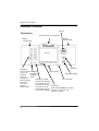
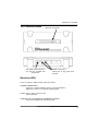
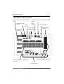
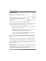
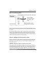
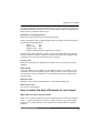
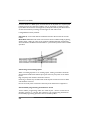
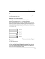
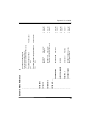
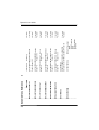
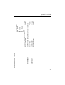
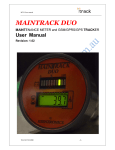
Dynamis User Guide
1
Dynamis User Guide
Contents
Introduction
3
Hardware overview Handset
4
Command station
5
Handset screen overview
6
Action key icons
7
Getting Started
8
How to use the joystick
9
How to configure the locomotive roster
9
How to manage consists
13
How to operate turnouts and accessories
15
How to program locomotive decoder CVs
16
How to configure using the System menu
17
How to make the best of Dynamis on your layout
19
Safety and care of your Dynamis
21
Fault finding
22
Other Bachmann E-Z Command® DCC products
23
Warranty information
23
Technical support
23
Dynamis Menu Reference
24
2
Dynamis User Guide
Introduction
Thank you for your choice of the Bachmann E-Z Command® Dynamis® DCC
model train control system. You have chosen an easy to use yet highly sophisticated
product. Please take a few moments to become familiar with the product by reading
this manual before proceeding. Using the Dynamis DCC system is simple as all
actions are guided by the screen icons with four Action Keys beneath.
The Dynamis DCC system features a powerful bi-directional infrared hands- free
control unit for convenient operation around your layout. Information passes both
ways between Command Station and Handset to ensure communication integrity.
Both units have been designed to have a wide transmission and reception arc for
optimal performance.
Dynamis can be used with model trains of any scale: power hungry Large Scale
trains may require the use of the E-Z Command® 5-amp booster.
This Dynamis starter system contains:
Wireless handset
Command Station with receiver
Lanyard
Track lead
AAA / MN2400 /LR03 batteries (4) for handset
Mains transformer
IMPORTANT
Bachmann E-Z Command® Dynamis® runs NMRA DCC decoder fitted trains
only: it does not run a train without a decoder. Damage may result to any train
without a decoder placed on a track powered by Dynamis.
Dynamis is a DCC system which is compliant with the NMRA DCC standards
3
Dynamis User Guide
Hardware overview
Joystick
The Handset
infra-red receiver / transmitter
Battery
compartment
Battery
compartment
Screen
Direction
Keypad for
direct control Headlights
Lanyard fixing
of up to 21 Locomotive
Emergency stop
functions,
headlights
accessory
on/off
hotkeys and
On / off switch
Shift key to switch
alpha numerical
between
the
function
keypad for
keys operating F1 to
loco and
F10 and F11 to F20.
accessory
Action keys
In accessory mode
address entry
sets function keys to Left hand is MODE key to switch
be accessory hotkeys between locomotive and
accessory control
4
Dynamis User Guide
The Command Station
DC power pack connector
Use only the supplied wall
transformer
Receiver connection
Output connectors,
3.5mm jack or plug with screw
terminal
Receiver LEDs
There are indicator LEDs located within the receiver
NORMAL OPERATIONS
Left hand - constant indicating power to Command Station
Right hand - flashes on receipt of Handset signals
STOP pressed / short circuit on track
Left hand flashes
HANDSET OUT OF RANGE OF COMMAND STATION
Left hand and Right hand both flash rapidly
5
Dynamis User Guide
Handset screen overview
Indicators for decoder function status
on/off
Shift key pressed
indicator
Consist
indicator
Headlights on
indicator
Text, including loco details and
menus etc
Track short circuit reported by Command
station
STOP
indicator
Low battery power
infra-red signal
condition
Used only when
the Dynamis Pro
Box is also used
Speed and direction indicators
Action Key icons
6
Dynamis User Guide
Action key icons
Icon
Key purpose when icon shown
Referred to as
Add loco to / remove from Consist
[CONSIST]
Select locomotive by address
[LOCO]
Turnout / accessory operation - turnouts
left / right or accessories on / off
[DIVERGE]
or
[STRAIGHT]
Access the menu
[MENU]
Accept
[ACCEPT]
[CANCEL]
Cancel
Scroll left or right
Move between CV selection and value for
CV in the programming menus
[SCROLL]
[CV<>]
[<>VALUE]
(reading CV values requires Dynamis ProBox)
[READ]
[PROG]
Backspace in text entry
[BKSP]
Write value to CV / read from CV
7
Dynamis User Guide
Getting Started
1. Attach lanyard to the handset. To avoid
dropping the unit use the lanyard around neck or
wrist.
2. Insert 4 AAA batteries into handset orientating
as shown on the diagram. The battery covers are
removed by carefully releasing the clips at the rear
of the handset
3. Connect receiver to terminal on top of the Command Station.
4. Place Command Station by layout, locating in a position with a good angle of view
to the Command Station infra-red receiver. Remove existing controllers / power
packs and connect the wires to the Command Station.
Use the red lead with jack plug to connect to Bachmann E-Z Track® or the
Bachmann Branchline track powerclip
Other leads with bare wire connectors can be connected to the green
connector block which plugs to the Command Station. This is
recommended for layouts using higher track power.
Please refer to ‘How to make the best of Dynamis on your layout’
section for advice on connecting to existing layouts
5. Select the appropriate mains pins for the wall transformer: they fit and lock in
place with a twist action. THIS PROCEDURE SHOULD BE CARRIED OUT BY AN
ADULT
6. Connect the power supply lead to the Command Station. Plug the transformer
into wall socket. The LED on the Command station receiver will be illuminated.
7. Turn on the Handset with the switch underneath – the Handset always powers up
with the STOP cutout in place (press STOP button to proceed) and ready to run a
locomotive with address 3.
8. Place a locomotive on the track. New DCC locomotives or decoders are shipped
with an address of 3.
To run a locomotive with a different address, press [LOCO] key and then enter
locomotive address and press [ACCEPT]. This locomotive number shows on the
screen along with a default roster entry that has been created.
8
Dynamis User Guide
How to use the joystick
Increase speed, scroll through menus, text input
Scroll through
locomotives roster
and menus, text
input
Decrease speed, scroll
through menus, text input
9. Push the joystick upwards to move the locomotive, bring it downwards to bring
the locomotive to a stop. Change direction by pressing the direction button beneath
the joystick.
10. Leaving the first train running, select a second locomotive address using the
joystick or the [LOCO] key. Set the train running. Move back to the first train by
scrolling with the Joystick. When selecting another moving train the bar graph for
speed immediately shows current speed of that train so that any change to speed is
made from the speed at which it is currently travelling.
How to configure the locomotive roster
There is a 40 locomotive roster database recording details of the locos. When first
selecting a locomotive address to run a roster entry is created with default values.
Once there are 40 roster entries one must be deleted to allow any other
locomotives to be run.
EXAMPLE: Changing the address and defaults of locomotive
A short (up to 127) or long addresses (“4-digit”) can be written to a decoder by
programming using a Service Track with no other locomotives present otherwise all
locomotives will adopt the address. If necessary create a separate length of track
powered by your Dynamis for this purposes. Additonally, a short address can be
changed to another short address using Main Track / “Ops mode” programming if
9
Dynamis User Guide
the decoder allows (please check with decoder instructions: for example Bachmann
36-553 and 36-554 decoders will allow this) whilst other locomotives are on the
track.
Main track
Service track
YES
YES
Short address with decoder
not allowing Address (CV 1)
to be programmed on Main Track
NO
YES
Long address using any decoder
NO
YES
Short address to another short
address with decoder allowing
Address (CV 1) to be
programmed on Main Track
If in doubt about the decoder specification, use the SERVICE TRACK to write the
address.
The screen shows
LOC 0003
LOCOMOTIVE
0:28
0003
1. Changing the locomotive address
The locomotive address can be set in either of two ways
Service Track
Main Track
-
all addresses 0001 to 9999
short addresses 1 to 127, only if allowed by the decoder
Using Main Track to change a short address to another short address
[MENU] -- scroll to
-- scroll to
PROGRAM
WRITE ADDR 0003
ON MAINTRACK
Screen shows
CHANGE ADDR LOC
WRITE ADDR 3
10
[ACCEPT]
[ACCEPT]
Dynamis User Guide
[BKSP] to delete existing address
Use alphanumeric keys or joystick to enter new address up to 127
CHANGE ADDR 0003
WRITE ADDR 68
Press [PROG] to write the new address
Both decoder and roster database are updated.
Using Service Track
[MENU] -- scroll to
-- scroll to
PROGRAM
WRITE ADDR 0003
ON SERVICETRACK
[ACCEPT]
[ACCEPT]
Screen shows
WRITE ADDR LOC
WRITE ADDR 3
[BKSP] to delete existing address
Use alphanumeric keys or joystick to enter new address of up to 4 digits
CHANGE ADDR 0003
WRITE ADDR 4468
Press [PROG] to write the new address
Both decoder and roster database are updated.
2. Changing the locomotive name
Each locomotive in the roster can be given a name of up to 16 characters, which
could be its actual running number if longer than 4 digits. Choose any combination of
letters and numbers using the alphanumeric lettering by each function key to enter
the name.
[MENU]
EDIT NAME
LOCOMOTIVE 3
[ACCEPT]
SET NAME
LOCOMOTIVE 3
11
Dynamis User Guide
[BKSP] to delete ‘LOCOMOTIVE 3‘
Use alphanumeric keys or joystick to enter new name
MALLARD
[ACCEPT]
3. Changing the locomotive icon
Each entry in the roster can be given an indicative icon for the type of locomotive, or
none.
[MENU] scroll to
EDIT SYMBOL 4468
MALLARD
[ACCEPT]
SET SYMBOL
Scroll through the icons for DIESEL, STEAM, ELECTRIC or none
Choose STEAM
[ACCEPT]
4. Changing locomotive decoder speed steps
Most decoders operate on 28 or 128 speed steps. Consult your decoder instructions
for information.
[MENU] scroll to
EDIT SPEED 4468
MALLARD
[ACCEPT]
Scroll
SET SPEEDSTEPS
14 / 28/ 128 speedsteps
Choose 128
[ACCEPT]
5. Changing the function setting
12
Dynamis User Guide
The control of each function on the decoder locomotive can be set to latch or
trigger
Latch – once pressed the function output is activated until the key is pressed again to
turn off
Trigger – the function is only activated for the duration of the press
Example:
The headlights of a locomotive would have a latch setting so that
the are left on until turned off again.
A coupling sound would have a trigger setting so that it can be
played when required with a key press.
[MENU]
EDIT FXMODE
LOCOMOTIVE 4468
[ACCEPT]
SET FUNCTIONS
LATCHING
Use the function keys to select the function outputs of the decoder that are to latch.
When the indicator shows on the screen the function is set to latch.
[ACCEPT]
The Screen now shows
LOC 4468
MALLARD
1/128
6. Deleting a locomotive
The roster entry can be deleted when no longer required. The currently controlled
locomotive cannot be deleted unless it has a speed of 0.
How to manage consists
13
Dynamis User Guide
‘Consist’ is a term used to describe more than one locomotive or railcar each with
its own decoder address being run at the same time as a single entity. ‘Double
header’ or ‘multiple unit’ might also be used, but for simplicity the term ‘consist’ will
be used here.
1. To add current loco to a consist:
NOTE a locomotive in a consist may have to run ‘backwards’ when the consist is
running forwards – for example a pair of diesel locos with their cabs outwards. Use
[DIRECTION] to set one of the pair in the reverse direction before putting in the
consist.
Press [CONSIST]
ADD TO CONSIST
CONSIST ID 0
- choose a consist number in range 1 to127
A consist cannot have the same number as a locomotive already in the roster
[CANCEL] to cancel
[ACCEPT] to accept
CONSIST TYPE
Scroll to choose UNIVERSAL or ADVANCED
Universal Consists are handled by the Dynamis unit
Advanced Consists are a decoder feature – check that the decoder you are using has
CV19 to allow this feature.
The consist indicator will now be showing against this locomotive
Each consist has it own place in the roster.
UNI
ADV
C001 indicates consist 001 is universal
C002 indicates consist 002 is advanced
[ACCEPT]
Each consist can be given a name
14
Dynamis User Guide
eg PAIR OF 20s or UP DASH 8s or TWO BR 218s
The consist can be controlled by:
Either consist address
or
any of the individual locomotive addresses
Locomotive functions are controlled from the locomotive address.
2. Removing a loco from a consist
Scroll through the roster to the locomotive.
Press [CONSIST]. The locomotive is removed and the consist indicator no longer
shows.
3. Deleting a consist
Once empty, a consist record can be deleted
How to operate turnouts and accessories
Press [MODE] to move the Handset into accessory mode
Screen shows
ACC A001 :01/1:
This indicates accessory address 1 which is accessory decoder 1, output 1, assuming
standard 4-output units
Scroll to using joystick, or enter an address with the numeric keys
ACC A067 :17/3
Accessory address 67 accessory decoder 17, is output 3
Addresses up to 100 (25 decoders) can be supported
Change direction by pressing [DIVERGE] or [STRAIGHT]
Creating accessory hotkey
15
Dynamis User Guide
A ‘hotkey’ shortcut from the numeric keypad can be set. The actual address of any
particular accessory can be assigned to any of the 10 hotkeys available.
By default, the hotkeys are accessory addresses 1 to 10.
For example, the 10 most important turnouts on the layout can be given the
shortcut.
In accessory mode SCROLL to the accessory address to be given an hotkey
[MENU] edit Hotkey A060 [ACCEPT]
Set HOTKEY
HOTKEY 0 | A005
Enter the hotkey to be given to this accessory address
[SELECT]
Using an accessory hotkey
Press [SHIFT] when in accessory mode.
Keys [F1] to [F10] control the 10 accessories given a hotkey shortcut.
Change direction by pressing [DIVERGE] or [STRAIGHT]
Programming an accessory decoder
Please refer to the instructions accompanying the E-Z Command Dynamis accessory
decoder (item number 36-561) or E-Z Track digital turnout or
www.dynamisdcc.com for more information.
How to program locomotive decoder CVs
CVs - ‘Configuration variables’ - are storage slots within the decoder which hold
values to control its performance. Different decoders have a differing selection of
CVs according to their specification. They control many different aspects of the
decoders performance: eg maximum or minimum speed, how the headlights operate
or whether the decoder operates on a DC supply. Refer to the instruction sheets
that came with your decoder or locomotive for details of the features that are on
your particular locomotive’s decoder.
Dynamis has the capability of programming in one of two methods:
‘Operations Mode’ (also called ‘Main track programming’) - other locomotives can
be left on the track as the programming instruction is sent to the particular decoder
address.
‘Service Mode’ makes the entire layout a service track. All decoders present on
the layout will receive the programming instruction. Other locomotives should be
16
Dynamis User Guide
removed from the track if using this method, or the locomotive programmed on an
isolated Service Track. Decoders that do not accept Operations Mode programming
should be programmed on a Service Track. Service mode also allows decoder CV
values to be read: this is possible using the Dynamis ProBox.
Service Mode can be any of the following according to the requirements of the
decoder:
Direct mode
‘CV’
Paged mode
’PM’
Register mode ’RM’
Each with or without programming track power down
Most modern decoders work with Direct mode programming. Dynamis allows any
or all of these methods to be set for a single programming session: adding modes
adds to the time taken to program. Select the programming methods required using
the System menu (see page 18).
Setting of locomotive decoder addresses is covered in ‘How to configure the
locomotive roster’ on page 10.
Some CVs are common to all decoders, eg CV 2 start speed or CV 29 configuration.
Others are specific to the decoder. The Handset shows the description of common
CVs.
EXAMPLE
To restrict the the maximum speed of a locomotive using Main Track programming
PROGRAM
4468
ON MAINTRACK
[ACCEPT]
POM CV 0
VAL 0 00000000
Set the value contained in CV5 to 20
POM CV 5
V HI
[<>VALUE]
VAL 20
[PROG] the chosen value is written to the decoder
[CV<>]
to continue programming another CV or
[CANCEL] to return to menu
17
Dynamis User Guide
How to configure using the System menu
Please refer to the full menu breakdown at page 24.
Joystick speed delay
Determines time before the speed repeat action is in effect.
Joystick speed repeat
Determines the rate of increase of speed on joystick movement.
Adjustment to these two settings changes the way the Handset actions
speed increases in response to joystick movements
Joystick menu delay
Determines time before move to the next menu item when the joystick is held to
left or right.
Joystick menu repeat
Determines speed of scroll through menus.
Adjustment to these two settings changes the way Handset moves through
the menus in response to joystick movements
Backlight brightness
A higher value gives greater intensity of illumination.
Backlight duration
Sets the length of time before the screen backlighting illumination turns off.
A higher value gives a longer period of illumination.
A setting of 0 means the back light remains on constantly.
Edit stop mode
Set to either
POWER OFF to cut the power from the track to stop all trains running
or
ESTOP LOCOMOTIVE to bring the train currently under control to a stop.
Any other trains running will continue.
Holding down the STOP button for a few seconds cuts the power from the
track to stop all trains.
It’s recommended that the ESTOP LOCOMOTIVE setting is for advanced users only.
18
Dynamis User Guide
Edit track timeout
The Dynamis Handset and Command Station stay in contact. If the line of sight is lost
the Command Station cuts track power. Use this setting to adjust the length of time
before power is cut when contact is lost.
Edit Service Track Programing
Selects the modes used for Service Track programming.
Select a combination of the programming methods according to the requirements of
the decoder being programmed.
Direct
‘CV’
Paged mode
’PM’
Register mode ’RM’
With or without programming track power down.
èMost decoders will accept Direct Mode - leave at this setting unless a decoder has
another requirement. Please consult you decoder instructions. More programming
methods in use at one time increase the time to program.
Factory reset
Restores the default values, deleting all locomotives that are stored in the roster
database.
Edit base ID
4 infra-red channels are available so that different layout in proximity can be
controlled. The Command Station jumper and the handset to must operate on the
same channel. Leave at 0 unless two or more Dynamis systems are being used in
close proximity.
Edit base name
Allocates a name to the Command Station - used with the ProBox only
Edit remote name
Set a name for the Handset.
How to make the best of Dynamis on your layout
What kind of turnouts should be used?
Either ‘live’ or ‘dead’ frog turnouts can be used with Dynamis, to the layout builder’s
choice – dead frog turnouts are easier to install as the live frog turnout usually
requires extra wiring. Details of the requirements included with the particular
products.
19
Dynamis User Guide
For best results on a DCC layout, turnouts that do not self isolate are required. (Self
isolating turnouts are those that enable a train to be parked in a siding on a DC
layout when the turnout is closed against it.) Ideally the whole layout should be live
so that trains stationary in sidings can have lights on and make sound.
If using Bachmann track products:
E-Z Track ® can be used without modification because the turnouts do not self
isolate.
Branchline track does self isolate. The turnouts can be modified simply by placing
staples (larger, staple gun type) at the locations indicated although permanently
wired connectors would be recommended for a permanent layout to ensure reliable
operation.
Connecting to an existing layout
When connecting Dynamis to an existing layout, existing controllers should be
disconnected and all block switches (if any) turned on to put power to the whole
layout.
High frequency track cleaners should be removed.
Reversing or station stop modules used on DC layouts cannot be used on a DCC
and should be removed.
Do not use track power connectors that incorporate interference suppressors.
Service Mode programming and a Service Track
‘Service Mode’ programming makes the whole layout a Service Track and all
decoders present on a layout will respond to the programming instructions.
Unintended programming operations can be avoided by either:
20
Dynamis User Guide
- remove all other locomotives from the track whilst programming
Or:
create an isolated section of track to be a separate Service Track. Either disconnect
your Dynamis Command station from the layout and connect to short length of
track, or create separate block section on the main layout that can be separated
from the remainder with a switch.
What is the rating of the track power?
The voltage is stabilised at 15.5v ± 5%, with 2.3 amps of power.
How to use one Dynamis system in proximity with another
So that multiple Dynamis systems can be used in proximity, there are 4 infra-red
signal channels available. The default setting of 0 should not be changed unless
necessary to avoid a conflict with another Dynamis system in use in close by. Set the
jumper plugs to the pins below the unit to use channels 1, 2 or 3 instead of 0, to
match the channel set on the Handset. The pins are marked under the unit. Channel
0 uses no jumper plugs.
Safety and care of your
Dynamis
Use under adult supervision.
Only use the supplied power supply, taking care with the power lead. The
appropriate mains pins for the local electricity supply requirement should be fitted
by an adult: THE MAINS TRANSFORMER AND ITS PINS ARE NOT A TOY. Do
not use if the cable becomes damaged. Contact a Bachmann Service Department
should a replacement power supply be required.
21
Dynamis User Guide
Use only for the control of model trains.
Wipe only with a damp cloth - do not immerse in water or use any other cleaning
agents.
For indoor use only - don’t allow to become wet.
The handset is a precision item and should be treated with care - always use the
lanyard to avoid dropping.
Batteries
Use AAA / MN2400 / LR03 batteries
Alkaline or NiCad or NiMH rechargeable batteries are suitable
Insert into the handset with correct polarity
Follow guidelines on the use and disposal of batteries
Remove batteries from the handset when not in use to avoid
damage from leakage
Fault finding
I can’t run a train with my Dynamis system
Power supply not connected to Command Station - LEDs will illuminate on
Command Station when power is applied. Connect power.
No connection to track - check connections.
Battery low indicator on Handset - replace batteries.
STOP or Short circuit indicator on Handset - check cause and press STOP to reset
unit.
Handset out of range of Command Station- STOP will be illuminated - press to
reset. The LED on the Command Station receiver flashed when signals are received.
Incorrect address of loco selected - check loco address and select locomotive with
correct address.
Handset and Command Station not on same channels - check setting of Handset and
set Command Station jumpers to the same channel.
22
Dynamis User Guide
Other Bachmann E-Z Command® DCC products
that can be used with Dynamis
36-507 Dynamis ProBox
Upgrade your Dynamis system to operate with up to 4 wireless handsets,
plus a programming track, a bus connector for wired throttles and devices,
and more.
36-561 E-Z Command® accessory decoder for turnouts etc
36-520 E-Z Command® 5 Amp Power Booster
36-525 E-Z Command® Reversing Loop Module
Bachmann E-Z Command® decoders and DCC Onboard models are also available
from your retailer.
Warranty information
Please refer to the enclosed sheet accompanying this user guide.
Technical support
Visit the Dynamis website www.dynamisdcc.com for technical information, updates
and further information or conctact us at one of these addresses.
Bachmann Industries, Inc
1400 East Erie Avenue
Philadelphia
PA 19124
USA
Tel: 1-800-356-3910
Bachmann Europe PLC
Moat Way
Barwell
Leicestershire
LE9 8EY
United Kingdom
Tel: + 44 1455 841756
Niederlassung Deutschland
Am Umspannwerk 5
90518 Altdorf b. Nürnberg
Germany
Tel: + 49 9187 97220
Dynamis is a registered trademark of
Bachmann Europe plc
E-Z Command and E-Z Track are
registered trademarks of Bachmann
Industries, Inc
23
24
1
EDIT NAME
|
|
|
EDIT SYMBOL
|
|
EDIT SPEED
|
|
EDIT FX MODE
|
|
|
|
|
DELETE LOCO or CONSIST
|
|
PROGRAM
|
|
|
|
Choices
to accept
to cancel
to accept
to cancel
to accept
to cancel
SET SPEEDSTEPS SCROLL: 14 / 28 / 128
Sets speed steps decoder is operating at
SET FUNCTIONS TO LATCHING
SELECT: F0 / F1 / F2 / F3 / F4 / F5
F6 / F7 F8 / F9 / F10 / F11 / F12 /F13
F14 / F15 / F16 / F17 / F18 / F19 / F20
Sets individual functions to latch or trigger
CONFIRM DELETE
Deletes locomotive or consist record from database
WRITE ADDR ON MAINTRACK
Writes a locomotive address using Programming on Main / Ops Mode
|
WRITE ADDR ON SERVICETRACK
Writes a locomotive address using Service Mode*
to accept
to cancel
to accept
to cancel
Action
SET SYMBOL
SCROLL: Diesel / Steam / Electric / None
Choose indicative symbol for locomotive or consist
SET NAME
KEY: up to 16 characters free text
Set 16 character name for locomotive or consist
Option
Press [MENU] and scroll the menu with [SCROLL] or the joystick Press [CANCEL] to move back up the menu
Dynamis Menu Reference
Dynamis User Guide
2
|
READ ADDR ON SERVICETRACK
|
Reads address using Service Track
|
(Function operates with DYNAMIS PRO box only)
|
|
|
PROGRAM ON SERVICE TRACK
POS CV number
|
VAL
value
|
|
|
PROGRAM [CURRENT LOCO]ON MAINTRACK
POM CV number
|
VAL
value
|
|
SYSTEM MENU
|
EDIT BASE ID
SET BASE ID
Enter number
|
Default = 0
Range 0-3
|
EDIT REMOTE ID
SET REMOTE ID
Enter number
|
(Feature set with DYNAMIS PRO box only)
|
SYSTEM INFO -------|
|
EDIT BASE NAME
SET BASE NAME Enter name
|
|
|
|
|
|
BASE SERIAL NUMBER
U00000000
|
|
|
|
|
BASE INFO_0
version number
Read Only
|
|
|
EDIT REMOTE NAME
SET REMOTE NAME Enter name
|
|
Default: Dynamis Remote
Dynamis Menu Reference
to accept
to cancel
to cancel
to accept
to cancel
to accept
to cancel
to accept
to cancel
to accept
to cancel
Dynamis User Guide
25
26
|
|
|
REMOTE INFO
|
EDIT JOYSTICK SPEED DELAY
|
|
EDIT JOYSTICK SPEED REPEAT
|
|
EDIT JOYSTICK MENU DELAY
|
|
EDIT JOYSTICK MENU REPEAT
|
|
EDIT BACKLIGHT BRIGHTNESS
|
|
EDIT BACKLIGHT DURATION
|
|
EDIT STOPMODE
|
|
|
EDIT SRV TRK PROG
|
|
|
|
|
Dynamis Menu Reference
3
to accept
to cancel
to accept
to cancel
to accept
to cancel
to accept
to cancel
SET JOYSTICK MENU REPEAT Enter value
Default = 63
Range 0 - 63
SET BACKLIGHT BRIGHTNESS Enter value
Default = 6
Range 0 - 8
SET BACKLIGHT DURATION Enter value
Default = 60
Range 0 - 255
SET STOPMODE
SCROLL: POWER OFF / ESTOP LOCOMOTIVE
Sets action on use of STOP button Default = Power off
SCROLL: CV Powerdown
CV RM
CV RM Powerdown
CV PM
CV PM powerdown
CV PM RM
to accept
to cancel
SET JOYSTICK MENU DELAY Enter value
Default = 8
Range 0 - 63
SET SRV TRK PROG
to accept
to cancel
SET JOYSTICK SPEED REPEAT Enter value
Default = 12
Range 0 - 63
to cancel
to accept
to cancel
Read Only
SET JOYSTICK SPEED DELAY Enter value
Default = 8Range 0 - 63
version number
Dynamis User Guide
|
|
|
|
|
|
|
|
|
|
EDIT TRK TIMEOUT
|
|
|
FACTORY RESET
Dynamis Menu Reference
4
ARE YOU SURE ?
Reset the default values
to accept
to cancel
SET TRK TIMEOUT SCROLL: No timeout / 7.5 sec / 15 sec / 30 sec
to accept
Default = 30 sec
to cancel
CV PM RM powerdown
RM RM powerdown
PM
PM powerdown
PM RM
PM RM Powerdown
CV
Select Service Track programming methods to use
to accept
Default = CV Powerdown
to cancel
Dynamis User Guide
27
Dynamis User Guide
Visit the
Dynamis website
www.dynamisdcc.com
Text copyright © 2007 Bachmann Europe plc
Printed in China
Dynamis User Guide V01 Aug 07
28