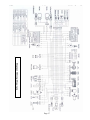
1
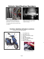
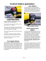
E-TON
Beamer Scooter
OWNER’S MANUAL
Dear Customer,
Thank you for choosing the ETON Beamer.
This scooter was made in accordance with the international QS9000 standards and the directives of the
European parliament and council. It conforms to all Federal DOT regulations for a class A moped.
It was engineered and designed to provide a reliable form of economic transportation for your life style.
This manual was designed to provide you with the basic understanding of the structure, function,
operation and maintenance of the Beamer Scooter. By following the instructions in this manual, you will
be able to maintain the performance and prolong the service life of your Beamer Scooter.
We at ETON wish you many years of pleasurable driving.
ETON America, LLC.
Important Notices
READ and UNDERSTAND this owner’s manual
The operator should completely read and understand this owner’s manual before
operating this vehicle. This owner’s manual will instruct you in the safe operation of the vehicle.
This manual contains warnings and cautions for some specific service methods which could
cause personal injury and/or damage to the vehicle.
ALWAYS Wear Protective Clothing
While operating this vehicle, the driver must always wear protective clothing. Protective
helmet with face shield, and hard soled boots should always be worn when operating this
vehicle.
OBEY all State and local laws and regulations
Each state and local governing agency has laws and regulations for scooter operations.
It is the owner’s responsibility to know, understand and obey these laws and regulations.
SPEED RESTRICTION Devices
This vehicle is equipped with electronic speed limiting devices. Any attempt to change,
over-ride or bypass these devices may cause dangerous operating conditions.
Due to continuing upgrades to our product line, information in this manual is subject to
change without notice. Please contact your local dealer for further information regarding
current information about your Beamer scooter.
Page 1
Table of Contents
Vehicle identification number location
Controls, switches and feature locations
Control feature operations
Engine stop switch
Turn Signal Switch
Horn Button
Head Light Control Switch
Ignition Switch
Instrument Cluster
Throttle Control
Throttle Cable Adjustment
Brake Systems
Front and Rear brakes
Front Hydraulic Brake Inspection
Hydraulic Fluid Reservoir
Purging the brake lines
Rear Brake Inspection
Fuel System
Fuel tank
Fuel Cap
Inline Fuel Filter
Engine Oil
Oil Indicator light
Oil Tank
Tires and Wheels
Tire pressure
Spark Plug
Spark Arrester Screen
Air Filter
Electrical Battery
C.V.T. Air Filter (Transmission)
Front Forks
Beamer Break-In Procedure
Pre-Operation Inspection
Starting procedure
Driving
Parking
Specifications
Maintenance Schedule
Wiring Diagram Viper 50
Manufacture’s Warranty
Owner’s notes
Page 2
3
3
4
4
4
4
5
5
6
6
6
7
7
8
8
9
9
9
9
10
10
10
10
10
11
11
11
12
12
12
13
13
13
13
14
14-15
16
17
18-19
20
Vehicle Identification Numbers
Vehicle Identification Number (VIN) is
located on the frame behind the foot
guard and is covered by a small plastic
cover plate which can be removed with a
screwdriver.
Engine serial number is located on the
left-hand side of the engine on the
crankcase housing.
Controls, Switches & Feature Locations
Locations of controls and features
1.
2.
3.
4.
5.
6.
7.
8.
Front Brake lever
Rear Brake Lever
Front Turn Indicator Lamps
Oil Tank
Main Parking Stand
Rear Turn Indicator Lamps
Fuel tank Cap
Brake Fluid Reservoir
D
DOT Information Plate
Page 3
Control feature operations
Horn Button
The horn button is a yellow push switch,
located below the turning signal lamp switch
on the left-hand handlebar. Pressing in on
the button will sound the audible horn signal.
Releasing the button will silence the horn.
Engine Stop Switch
The stop switch is a red colored rocker switch
located on the left-hand handlebar.
To start and run the engine, this switch must be
placed in the on, “O” position.
The vehicle is also equipped with a safety brake
switch which will prevent the engine from starting
until the parking brake is engaged.
To stop your engine, place the switch to the stop,
“X” position.
In the stop, “X” position the ignition system is
grounded preventing the spark plug from firing.
This switch can also be used as a safety or
emergency stop switch.
Turn Signal Switch
The turning signal switch is a three position
switch located on the left-hand handlebar. Sliding
the switch in the direction of the intended turn will
illuminate the front and rear turn signal lamps in a
blinking mode. Pressing the white button, on the
center of the switch, will return the switch to the
neutral position and cancel the illumination of the
turning lamps.
Head Light Control
Switch
For safety, the head light system of this unit
was designed to be illuminated at all times
while the unit is running. The intensity of the
light is changed by using the head light
control switch located on the right-hand
handlebar. It is a three position slide switch.
Far right position sets beam intensity to 20%
(Day Time Running), middle position sets
beam intensity to 80% (Low Beam), and far
left position sets beam intensity to 100%
(High Beam).
The vehicle is equipped with a PTC controller
that will dim the lights to the 20% position
automatically if the engine RPM falls below
the pre-set threshold for more than a minute.
Increasing the engine RPM will return the
light to the normal level for the control switch
selection.
Page 4
Instrument Cluster
The instrument cluster provides you with
operating conditions of your vehicle. To the
left is the fuel gauge which indicates the fuel
level in the fuel tank. When the needle
reaches the red zone on the gauge, you are
running low on fuel and the tank should be
refilled. This gauge is controlled by a fuel
level sending unit located inside the fuel tank.
Ignition Switch
The ignition switch is located on the control
column’s right side below the handlebars. A key
is required to work the switch. This switch has
three positions, “O” On, “X” Off and “±” Locked.
The switch must be in the “O” on position for the
engine to start and run. The “X” off position
disconnects power to the ignition and light circuits
and stops the engine. The “±” locked position,
locks the steering column and allows the key to
be removed. In order to turn the key to the “±”
locked position you must press down on the key
with the steering column turned slightly to the left.
NOTE: Always lock your vehicle when leaving it
unattended and take your keys for additional
security against theft of your vehicle.
The ignition key also unlocks your fuel cap and
under seat storage compartments.
The center speedometer indicates the
current speed of your vehicle. The
speedometer is calibrated in both MPH,
(Miles per hour) and KPH, (Kilometers per
hour). This gauge is controlled by a cable
attached to the front wheel of the vehicle.
The right side is a series of three indicator
lamps. The top most lamps in the cluster will
indicate that the turn signals have been
activated and also indicates which signal
lamps are illuminated.
The right indicator lamp indicates the head
light controller is in the Hi-Beam, 100%,
position when illuminated.
The left lamp indicates the 2 cycle oil level in
the oil tank. When illuminated your oil tank is
low and needs to be refilled. Continued
operation of the engine with a low oil
condition will cause sever damage to the
engine and potentially unsafe operating
condition. Refill your oil tank with High grade
JASO FC 2 cycle injector oil.
Page 5
Throttle Cable Adjusting
Throttle Control
The throttle control is the right-hand handle grip.
Throttle is controlled by twisting the grip.
The throttle control is spring loaded and set at the
factory to return to the idle position when
pressure is released.
To increase the throttle, twist the handle grip in a
counter clockwise rotation. To decrease throttle,
twist the hand grip in a clockwise rotation or
release your pressure and allow the throttle to
return on it own.
The throttle cable should be adjusted so there is
5-10mm, (¼”) free travel of the throttle hand grip
before the throttle starts to open.
Keep the throttle cable lubricated and operating
smoothly. If the cable sticks or is hard to operate,
lubricate the cable by disconnecting the cable
from the throttle hand grip and lubricating with a
commercial cable lubricant available at your
dealer.
Replace the cable if it shows signs of fraying or
corrosion or is kinked or bent.
To adjust the throttle cable’s free play, slide
the protective cover down the cable to
expose the cable adjusting system. Loosen
the locking nut and adjust the cable length by
turning the adjusting collar. Check the free
travel in the throttle hand grip until you have
5-10mm, (¼”) free travel. Tighten the
locking nut against the adjusting collar
and slide the protective cover over the
adjusting system. Replace the cable if
there is no adjustment remaining or the
proper free travel can not be obtained
with the adjustment system.
Front and Rear Brakes
This vehicle is equipped with front
mechanical hydraulic disc brake and a rear
mechanical drum brake.
The front brake is controlled by the long
brake lever on the right-handlebar.
The rear brake is controlled by the long lever
on the left-Handlebar.
The rear brake is the primary stopping brake
on your vehicle. Using the rear brake to stop
your vehicle will prevent steering control loss.
Use your front and rear brakes in
combination to control your speed while
descending a grade. Use caution not to apply
too much pressure to your front brake so that
the wheels lock up, stop turning, and cause a
loss of steering control. If the front wheels
lock up, stop turning, lightly reduce the
pressure on the front brake lever until it
unlocks and the wheel start to turn.
Page 6
The fluid level should fill at least ¾ of site
glass when the unit is setting on a level
surface.
Test the brakes by applying pressure to the
brake lever and trying to push the unit
forward. If the wheel rotates while the brakes
are applied, check your fluid level and brake
pads. If the brake lever feels spongy or does
not stop when squeezed, you may have air in
the lines. All air must be purged from the
brake lines for the disc brake to operate
properly. (See purging brake lines).
Front Brake System Inspection
Visually inspect the brake lines for any signs of
wear. Inspect the lines for leaks at all connections
and look for wear along the entire line. Replace
the line if any worn areas are found. The brake
line is under great pressure when the brakes are
applied and any worn spot could cause a rupture
of the line.
Inspect the brake arm, spring, rod and fastener
for signs of wear or damage. Operate the brake
lever while watching the brake mechanism for
proper operation. Tighten, repair or replace parts
as needed to insure safe brake operation. Clean
any build-up of mud or debris from the brake
mechanism.
The brakes are equipped with a wear indicator to
alert you when your brake pads need replacing.
Apply light pressure to the brake lever and slowly
push the unit forward. If you hear a high pitched
metallic scraping sound, you need to replace your
brake pads. The minimum pad thickness is
3.0mm.
DO NOT RIDE A VEHICLE WITH WORN
BRAKE PADS.
Check the rotor disc for cracks, warping or color
distortion. Replace rotor disc at first sign of
problem.
Check rotor disc thickness. Minimum thickness is
3.1mm. Replace the disc if below minimum
thickness.
To Fill the Reservoir
Remove the reservoir cover by removing the two
cover bolts.
Fill the reservoir to 1/8” from top with Dot-3 SAEJ1703 grade brake fluid.
Caution: DO NOT allow dirt to fall into the
reservoir.
Refold the cover gasket as shown in picture and
replace cover and bolts.
Check the fluid level in the fluid reservoir by
checking the site glass for the level.
Page 7
Purging Brake Lines
For the hydraulic brake system to operate safely, the
brake system must be purged of air in the lines and
reservoir.
the brake cable with a commercial cable
lubricant available through your dealer.
Test the rear brake by applying pressure to
the brake lever. Try pushing the vehicle with
the brakes applied. If the rear wheel turns the
To bleed the air will require two people to perform the
brakes may need to be adjusted or replaced.
following procedure.
1. Place a drain pan under the brake caliper to catch
the fluid.
2. Open the bleeder valve ½ turn counter
clockwise.
3. Squeeze the brake lever to expel air from the
system.
4. While holding the brake lever, close the
bleeder valve.
5. Repeat steps 2 through 4 until the brake fluid
coming from the bleeder valve is a solid
stream without any air, then close the valve
and replace rubber protection cap.
6. Test the brake system by squeezing the lever.
To adjust the rear brake, turn the adjusting
The lever should feel firm and stop without
nut located on the brake arm on the rear
fading.
wheel. Adjust the nut so that the brake arm
engages when ever the rear brake lever is
Rear Brake System Inspection
squeezed. CAUTION: do not over tighten the
nut to the point that the brake shoes are in
constant contact with the brake drum.
Replace the brake cable and/or shoes when
there is insufficient adjustment left to apply
the brake completely.
Rear brake drum tolerances are:
Check the brakes for smooth operation. The
brake cable should move freely and apply the
brakes with minimal effort. If the cable sticks,
hangs up, or requires a larger amount of effort to
apply the brakes the cable may be damaged or
need lubricating.
Inner diameter of drum
Standard: 110mm / 4.330696”
Minimum: 110.5mm / 4.350381”
Brake Shoe Lining
Standard: 4.0mm / 0.1574798”
Minimum: 2.0mm / 0.07873992”
Visually inspect the brake cable for any signs of
wear, fraying, kinking or corrosion. Replace any
worn, frayed, corroded or kinked cable. Lubricate
Page 8
Fuel System
or replace the seal if it becomes worn or torn.
The seal must be in good condition to insure
a proper seal of the cap to the tank to
prevent fuel spills. DO NOT allow dirt or
other debris to enter the tank when refueling.
Replace the cap if damaged or if it will not
seal to the tank.
The fuel tank capacity is 5.5 liters, 1.5 gal.
NEVER REFUEL YOUR VEHICLE when
Fuel Tank
The fuel tank fill cap is located at the rear of the
vehicle just behind the seat. Your vehicle is
equipped with a locking fuel tank cap that is
opened with the same key that is used in the
ignition switch.
To unlock your cap simply insert the ignition key
into the lock and turn clockwise until the cap
releases. Lift the cap from the tank and refuel
your vehicle with unleaded automotive grade
gasoline of 89 octane or higher.
To replace the cap, align the locator lug on the
cap with the notch in the tank neck and press the
cap down until you hear the locking lugs click.
the engine is running or with a hot
exhaust system. Wait 30 minutes after
turning off the unit before refueling. Spilling
fuel on a HOT engine or exhaust could cause
a fire. Wipe up any fuel spills before restarting.
Inline Fuel Filter
Your vehicle is equipped with an inline fuel
filter to prevent dirt and debris from entering
the carburetor and engine.
The filter should be replaced every 10,000
miles or each year of operation.
Replacement and fuel line inspection should
be preformed by an authorized ETON dealer
only.
Every time you refuel your unit, check the rubber
seal inside the cap for cuts, tears and dirt. Clean
DO NOT start or operate the engine if the
fuel filter or lines are leaking. Leaking fuel
can cause a fire.
Page 9
Engine Oil
tank cover retaining screw and lifting the
Your vehicle uses 2 cycle oil to lubricate the
engine. The oil tank is located under the seat at
the front of the unit. Oil is drawn from this tank by
an oil injector pump when the engine is operating.
Oil Level Warning Light
cover. The oil tank capacity is 1.1 liters, 1.2qt.
Fill the tank with high quality JASO FC grade
2 cycle injector engine oil. Using lower grade
oil can cause exhaust smoke and result in
damage to your engine.
The unit is also equipped with an oil level
indicator lamp. The lamp will light when the oil
level in the tank is low. When the lamp is lit you
MUST refill the oil tank.
DO NOT allow the engine to operate with an
empty oil tank. Doing so will result in
extensive damage to your engine. This
damage is not covered under the warranty.
Check the oil tank level manually every 500 miles
of operation.
IMPORTANT NOTE:
Your first tank of fuel should be a pre-mix
fuel with a 50:1 fuel to oil ratio. This will
insure the engine is lubricated and give the
oil pump time to bleed any air from the oil
line that may have occurred during shipping.
If your unit is creating excessive smoke
from the exhaust insure that you have
used a JASO FC grade 2 cycle injector
oil in the tank. If you are sure your oil is
of the correct grade, your oil pump may
need adjustment. The oil pump must be
adjusted by an authorized ETON Dealer.
Tires and Wheels
The tires and wheels of your Beamer have
been engineered to match the suspension to
give you a smooth, comfortable ride. They
were also designed to afford you with
mileage economy, to give you the best miles
per gallon possible.
Tire Size & Pressure
The oil tank is located under the seat in the front
of the vehicle. It is accessed by removing the Oil
Recommended tire pressure (Cold) is:
Front 120/90-10 18psi / 1.25kg/cm2
Rear 130/90-10 25psi / 1.75kg/cm2
Page 10
Spark Plug
Replace the spark plug every 10,000 miles or if
the plug should become damaged or fouled.
We recommend that you use NGK - BPR7HS.
The air filter box is located on the left side of
the engine under the body cover. It is a black
box about 6” square and is attached to the
crankcase with two bolts and the carburetor by
a tube.
Disconnect spark plug wire.
Clean dirt from around spark plug base with
brush or air. (Caution: do not allow dirt or foreign
material to enter the engine)
Remove spark plug with spark plug wrench.
Set the spark plug gap on the new plug to 0.023”.
Install the new plug screwing it in finger tight and
then use the plug wrench to screw the plug in
another ½ turn.
Inspect the spark plug wire for cuts, nicks or other
damage. Replace as needed.
Air Filter
To clean the filter
Remove the air filter box cover.
Remove the filter element from the air box.
Wash the element in a non-flammable solvent
such as Air-Filter cleaner from your local auto
parts dealer.
1. Dry the element completely before
continuing.
2. Soak the element in clean engine oil
until completely saturated.
3. Squeeze out the excess oil until the
element does not drip any oil.
4. Allow the element to dry then reinstall
the element and cover.
Air Filter Maintenance
To maintain the highest performance from your
engine and to reduce excessive wear that could
cause engine failure the engine requires a
continuous flow of clean air. Air is taken into the
engine through an air filter to clean the air prior to
mixing it with fuel and oil in the carburetor.
During normal operation the filter accumulates
dirt from the air and will need to be cleaned to
maintain the proper air flow. The filter should be
cleaned every 3000 miles, more often if you ride
in a dusty or dirty environment and the element
should be replaced every year.
Page 11
Electrical Battery
There is an inline fuse on the positive lead of
the battery to protect the wiring system from
over loads. If your starter motor will not turn
over and the battery is fully charged, check
the inline fuse on the unit.
Replace the fuse with a 7A fuse.
C.V.T. Filter
The unit’s battery is located under the floor board
mat and supplies electrical power to the unit. The
battery is a 12 volt gel acid type that contains no
liquid electrolyte. The battery should be removed
from the vehicle when stored for extended
periods and charged before being replaced in the
unit. Use a trickle charger set at 12 volts to
recharge the battery to full charge before
replacing it in the unit.
When reinstalling the battery, be sure to connect
the red cable to the positive (+) terminal and the
black cable to the negative (-) terminal.
This unit is equipped with an air filter for
the C.V.T. transmission. It is located on the
left-hand side of the engine, just ahead of
the kick starter spindle. The filter will
accumulate dust and must be cleaned
periodically to maintain normal vehicle
operations. Inspect and clean the filter
every 3000 miles, more frequently if
operated in a dusty environment.
To clean the filter, remove the two cover
bolts and remove the filter. Clean the filter
element in a non-flammable solvent and let
dry completely before reinstalling. Replace
the filter element and the cover.
FRONT FORKS
Check the front forks of your vehicle for signs
of damage or leaking oil. If either is noticed,
return the vehicle to your dealer for service.
The battery should be replaced every three years
or when it no longer holds a charge.
Do not expose the battery, for extended periods
of time, to freezing temperatures. If the battery
has been frozen it will need to be replaced.
Page 12
11. Insure you are wearing proper
clothing and protective gear, such as
helmet and hard soled shoes.
Beamer Break-In
procedures
Your Beamer requires a break-In period just as
with all other internal combustion engines. This
period allows the engine parts to seat and wear
properly without undue strain which can cause
premature failure.
1. For the first 1000 miles of operation do not
operate your vehicle above 18mph. for
extended periods of time.
2. Your first tank of fuel should be a premixture of fuel and oil at a 50:1 ratio. This
will insure that the oil pump system has
been primed and bled of air that may have
occurred in shipping.
3. Do not over rev the engine.
4. Use light braking pressure to allow the
brake pads to seat to the rotor and drums.
Pre-Operation Inspection
procedure
The following procedure must be performed
before each operating session.
Checking your Scooter takes only a few minutes
and may save you from serious injuries and
costly repairs.
1. Check engine oil level.
2. Check engine fuel level.
3. Check brake operations and brake fluid
level.
4. Check tire condition and pressure.
5. Check throttle operation and free play
adjustment.
6. Check engine stop switch for proper
operation.
7. Check steering system. Look for free and
smooth operation. Check all fastening
hardware.
8. Check all nuts, bolts and other fasteners
for loose conditions.
9. Inspect unit for any broken or damaged
parts.
10. Check all indictor lights and switches for
proper operation.
Starting Procedure
The following procedure must be followed
each time you start your Beamer.
Park the unit on a level surface. Insert the
key into the ignition switch and turn to the
“ON” position.
Turn the engine stop switch to the “ON”
position.
Apply slight pressure to the throttle grip.
Hold in both brake levers while pressing the
starter button on the right handlebar switch.
NOTE: Your Beamer is equipped with a
safety brake interlock switch which will
prevent the engine from starting without the
brakes being applied.
Your unit should start within 10 seconds of
pushing the starter button. If the unit fails to
start check the following:
1. Engine stop switch is “ON”.
2. Brake levers applied
If your battery does not have enough charge
to turn the starter motor you can use the
alternate kick starter to crank the engine.
Swing the kick starter foot peddle to the out
board position and while holding both brake
levers, apply a quick downward push to turn
the engine over.
Driving your Beamer
Your Beamer was manufactured to meet all
Federal D.O.T. regulations. State and local
regulations govern the use of this class of
vehicle. Check with your local DMV office
before riding this vehicle on the highway.
Set yourself in a comfortable position on the
seat with both hands on the handlebars.
Ensure that you have an unobstructed
operating area from which to control your
Beamer. When carrying a passenger, always
insure that they place their feet on the
Page 13
passenger pedals. Always keep your feet on the
footrests and your hands on the handlebar grips
while operating your Beamer. Doing so will give
you the best control of the unit.
Be sure that you and your passenger are NOT
wearing loose fitting clothing that could become
entangled in the moving parts of the vehicle.
Start the vehicle in a forward motion by slowly
increasing the throttle pressure.
It is not recommended to operate this vehicle
in slippery conditions such as on snow or ice
covered roads.
When going downhill, release the throttle grip
and use your brakes to control your speed.
After washing your vehicle your brake shoe
and pad may have become wet and will
reduce the braking force until they have had
a chance to dry.
Never place more than 12lbs / 5kg load on the
rear rack. Doing so may cause the vehicle to
become unbalanced and cause an unsafe driving
condition.
Never carry anything on the handlebars or your
lap while driving your vehicle. Doing so can cause
a loss of control over the vehicle.
Learn to steer your scooter by shifting your
weight in the direction of the turn. (Lean into the
turn)
Parking Your ATV
1. Always park your vehicle on a level
surface.
2. Turn the ignition key to the “OFF’”
position to stop the engine.
3. Set the engine stop switch to “OFF”
position.
4. Turn your front wheel slightly to the
left and turn the ignition key to the
lock position to lock the steering
column.
5. Remove the ignition key to prevent
unauthorized use or theft of your
vehicle.
6. Park the vehicle by using either the
main parking stand or the side kick
stand. The stands are located on the
left –hand side of the vehicle.
Use your front & rear brakes to control your
speed and to stop. Sudden braking force can
cause the vehicle to start sliding. To regain
control, release the braking pressure until you
have regained control of the vehicle.
When the road surface is wet, the braking
distance is double that of when the road surface
is dry.
Keep a safe distance between yourself and the
vehicle in front of you.
Page 14
Beamer Scooter Specifications
Beamer (Model - PN2)
Engine
Type
Displacement
Bore / Stroke
Compression
Power
Two cycle air cooled oil injected
49.3cc
φ40.0 * 39.2mm
6.8 : 1
5.2hp @ 7000rpm
Beamer Scooter Specifications (Continued)
Transmission
Type
Automatic (C.V.T. V-Belt)
Chassis
Overall Length
Overall Width
Overall High
Wheel Base
Dry Weight
1830mm / 72.0"
650mm / 25.6"
1100mm / 43.3"
770mm / 30.3"
82kg / 180.7lb
Suspension
Front
Rear
Telescopic Fork
Unit Swing Arm / Single Shock
Brakes
Front
Rear
Hydraulic Disc
Mechanical Drum
Tires
Front
Rear
120/90-10
130/90-10
Tire Pressure
Front 18psi / 1.25kg/cm2 (Cold)
Rear 25psi / 1.75kg/cm2 (Cold)
Carburetor
Make/Size
Main Jet
Pilot Jet
Mikuni 18mm (Electrical Choke)
85mm
20mm
Air Mixture Adjustment
Back out ¾ - 1¼ turns
Idle 1700 - 1900rpm
Battery
12V-4AH/5AH - GTX5L-BS
Fluids
Fuel
2 Cycle Oil
Transmission
Type
Volume
Type
Volume
Type
Volume
Unleaded Gasoline 89 octane
5.5liters / 1.5gal
High grade synthetic 2 cycle injector oil
1.1 liters / 1.2qts
SAE 80/90 weight
100cc / 3.4oz
Page 15
Spark Plug
NGK (recommended)
Nipendenso
Champion
Electrode Gap
Max Driver & Passenger Weight
BPR7HS
W22FRP-U
QL82YC
0.6-0.7mm / 0.023"
150kg / 330lbs.
Subject to change without notice
10/01/203
Maintenance Schedule
First week
Every 30 Days
Every Year
I
Fuel Lines
Throttle Operation
Air Filter
Fuel Filter
Spark Plug
Drive Chain
Brake Shoes
Brake System
I
I
C
I, L
R
R
R
I
I, L
I
I
I
Inspect as part
of pre-ride
inspection
I
Inspect as part
of pre-ride
inspection
I
Brake Fluid
Bolts, Nuts & Fasteners
Wheels
Notes
Replace Fuel & Vent
Lines every 2 years
Inspect as part
of pre-ride
inspection
I
I
I
I
I
Steering system
Every 6 months
Suspension System
C.V.T. Filter
C.V.T. Drive belt
Transmission Oil
Choke
Spark Arrester
Battery
Replace every 2 years
Inspect as part
of pre-ride
inspection
Inspect as part
of pre-ride
inspection
Inspect as part
of pre-ride
inspection
I
C
I
R
Replace as needed
R
every 10,000 Miles
I
C every 100 hrs R every 200 Hours
I, C
I = Inspect, Clean, Adjust, Lubricate or Replace as needed
C= Clean
L = Lubricate
R = Replace
Page 16
Beamer Wiring Diagram
Page 17
ETON AMERICA, LLC.
LIMITED VEHICLE WARRANTY
ETON America warrants all new ETON vehicles sold by authorized Eton Dealers to be free
from defects in materials and workmanship, subject to the following exclusions and
limitations. New vehicles sold by an authorized dealer to original retail consumers are covered
by this policy for a period of six (6) months from the date of delivery. There is no mileage
limitation.
Vehicles used in rental service or for certain commercial purposes are specifically excluded
from this policy. (Check with your dealer for warranty application.)
Items and conditions that are specifically excluded from this warranty program are:
1. Damage caused by accidents, misuse, negligence, improper vehicle operation.
2. Any modification or alteration to any standard specifications or equipment.
3. Any repairs made by an unauthorized dealer or service firm.
4. Use of non-ETON genuine parts for repairs or alteration to standard specifications.
5. Damage caused by failure to perform factory scheduled service maintenance.
6. Damage which occurs as a result of improper storage.
7. Damage caused by the use of improper fuel or lubricants, and/or failure to use proper
oil/gas mixture on two stroke models.
The following normal wear parts are specifically excluded from warranty coverage:
1. Rubber parts
2. Tires
3. Belts
4. Brake linings
5. Normal wear item
6. Brake parts
7. Cables
8. Filters
9. Spark plugs
10. Bulbs
11. Batteries
12. Sprockets
13. External springs
14. Seat and hand grips.
Page 18
ETON AMERICA, LLC.
LIMITED VEHICLE WARRANTY
Scheduled maintenance service is the responsibility of the owner during and after the warranty
period. In the event of a failure or required repair, the owner should take the vehicle to an
authorized dealer for repair without undue delay and within a maximum of thirty (30) days of the
occurrence of the problem. All eligible warranty repairs must be made at any authorized dealer’s
normal place of business. Any transportation costs, or other expenses which may occur in order to
obtain warranty service, are the responsibility of the owner. All eligible repairs covered under this
warranty will be paid to the servicing dealer only, by ETON America, and no additional payments
shall be made for authorized warranty repairs.
Dealer and/or ETON America are not responsible for loss of use, other damage or inconvenience
due to warranty repairs. It is the customer’s/buyer’s responsibility to review with the selling dealer
the pre-delivery service schedule to assure that the machine is properly serviced prior to delivery
acceptance. It is recommended that the buyer take a test ride to familiarize themselves with the
machine and to make certain the unit is in proper operating condition. The dealer is responsible for
checking and performing all items on the “set-up and pre-delivery checklist” prior to delivery to
the customer.
This warranty is valid at any authorized ETON Dealer in the United States only. In the event you
experience any problem obtaining prompt service, contact ETON America’s customer service
department for assistance. Always consult first with your selling dealer and/or service personnel
for assistance with any service work or repairs. In the event you have a problem obtaining service
send your name, address, and vehicle identification number to Eton America for assistance.
The above stated policy is the only policy offered and backed by ETON America, and no other
organization or individual is authorized to make or offer any different arrangements. Some states
prohibit certain limitations or conditions or do not allow exclusions or limitations. You may be
eligible for additional consideration, so check with your local dealer or appropriate state agency
for assistance. Rights vary from state to state, and you may have other rights not offered in this
warranty.
ETON America warrants that all new vehicles comply with applicable US regulations.
Page 19
Owner’s Notes:
Page 20
Owner’s Notes:
Page 21
Owner’s Notes:
Page 22
Page 23