Download Alarm & Starter 2300 Series Specifications
Transcript
Softstarters
Type SSM, Medium voltage
2300 – 4160V
Specification Guide
Low Voltage Products & Systems
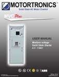
SSM Series Medium Voltage Solid State Soft Starter
2300 – 4160V, 200 – 600A
Overview: This detailed Specification Guide assists Plant and Consulting Engineers to specify and describe
the ABB SSM Series Digital Reduced Voltage Solid State Starter. This equipment is provided
as a superior method of providing soft start control and protection for AC motors. It also solves
performance control and reliability problems typical of electro-mechanical reduced voltage motor
starter methods, such as Part Winding, AutoTransformer, and Primary Reactors. Advantages
include solid state construction, advanced motor protection, stepless acceleration, reduced
inrush current, minimal maintenance and high duty cycle capability. Applications include, but
are not exclusively dedicated to: pumps, fans, blowers, grinders, compressors, lumber and rock
processing, conveyors, and mixers.
Softstarters
Type SSM Specification
Guide
Type SSM
Medium voltage
Installation & maintenance manual
Introduction....................................................................................................... 2
2.0 Codes & Standards.................................................................................. 2
3.0 Product Features..................................................................................... 2
A. Motor and Load Protection . ............................................................2-4
B. Acceleration Control . ......................................................................... 4
C. Deceleration Control .......................................................................4-5
D. Starter Protection................................................................................ 5
E. Inputs ................................................................................................. 5
F. Outputs.............................................................................................5-6
G. Operator Interface............................................................................... 6
H. Metering...........................................................................................6-7
I. Options................................................................................................ 7
J. Serial Communications....................................................................... 7
4.0 Design Specifications.............................................................................. 7
A. Power Ratings..................................................................................... 7
B. Power Structure...............................................................................7-8
C. SCR Modules...................................................................................... 9
D. Ambient Conditions............................................................................. 9
E. Electronic.......................................................................................9-10
5.0 Mechanical Construction....................................................................... 10
6.0 Quality Requirements....................................................................... 10-11
7.0 Documentation....................................................................................... 11
8.0 Spare Parts............................................................................................ 11
9.0 Field Acceptance, Testing and Training................................................. 11
Low Voltage Products & Systems
ABB Inc. • 888-385-1221 • www.abb.com/lowvoltage
3
1SXU132173M0201 [AC 1007.2] - 2/02
Type SSM Specification Guide
1.0 Introduction
This specification describes the performance, functional specifications and fabrication details for a digital reduced
voltage, stepless, solid state medium voltage motor starter that shall provide a selectable voltage ramp, current limit or
current ramp (all standard) method of soft starting 3-phase AC induction motors.
A) Each motor starter(s) shall be complete self-contained Class E-2 Combination Starters and house the fused
disconnect switch, in-line isolation contactor, solid-state controller, motor overload protection and bypass
contactor.
2.0 Codes and Standards
A) Unit(s) must be manufactured to the codes listed below:
ANSI American National Standards Institute
IEEE Institute of Electrical and Electronic Engineers
UL Underwriters Laboratories Inc.
NEC National Electrical Code
NEMA National Electrical Manufacturers Association
OSHA Occupational Safety and Health Act
B) Unit(s) must be approved and/or certified by, and carry the label(s) of Underwriters Laboratories (UL). Units
shall be UL / cUL 347 listed as a complete assembly, including all necessary sub assemblies and components
in the same package.
3.0 Product Features
Solid state reduced voltage motor starters shall be ABB’s SSM Series (sized as indicated), or pre-approved equal modified
to meet the requirements of this specification. The starter shall be complete with the following standard features and
adjustments.
A) Motor and Load Protection shall be integral to the starter assembly. Motor protection shall be based upon
modeling of the thermal characteristics of the motor as programmed by the user and measured by the starter.
All current referenced protection features shall be calculated from the motor nameplate FLA, and automatically
adjusted for the Service Factor, NEMA Design, Insulation Class, Line Voltage and Line Frequency as entered
by the user. All time based protection features shall be based on a Real Time Clock, remaining active through
any power loss. Starter shall provide the following functions:
1) Thermal Overload shall be provided by the on-board microprocessor control. Basic protection shall be
inverse time-current trip curves as defined by NEMA trip curve Classes. The trip curve classes shall be
programmable from between Class 5 and Class 30 and the starter shall be UL listed to provide each
individual class. As the most important protection feature of a starter, the overload protection shall be
based on a Dynamic Thermal Register retained in memory and provide the following features:
(a) Retentive Thermal Memory shall be used to ensure that the Dynamic Thermal Register does not
loose track of motor temperature after the power is lost or shut down. Upon reapplication of power, the
microprocessor shall be automatically updated as to the motor temperature and adjusted for real time
cooling while the power is off.
(b) Dynamic Reset Capacity shall retain a snapshot of the thermal capacity necessary to restart the
motor. The starter shall determine these requirements by recording and averaging the previous 3
successful start-ups. After an overload trip has occurred, the protection shall prevent resetting until
enough cooling time has passed and sufficient motor thermal capacity is available.
(c) True Thermal Modeling shall be a feature of the overload and reset calculations. Once established at
setup, the Dynamic Thermal Register shall be biased according to the following input information when
available: Cold Stall Time, Hot Stall Time, Stopped Cool Down Time, Running Cool Down Time, and all
of the real time information from the RTD Option if ordered.
4
1SXU132173M0201 [AC 1007.2] - 2/02
Low Voltage Products & Systems
ABB Inc. • 888-385-1221 • www.abb.com/lowvoltage
Type SSM Specification Guide
(d) Separate Trip Curves shall be provided for Start and Run, allowing a higher level curve to avoid
nuisance tripping during acceleration, but dropping to another level for accurate motor protection while
at full speed. To maximize flexibility, each trip curve shall be programmable as follows:
(i) Basic, using the NEMA Class ranges described above.
(ii) Locked Rotor programmable between 400 – 800% of FLA, and a trip time from 1–– 30
seconds.
(iii)Measured Start Capacity (I*I*T curve area) taken from the previous successful start (only
applicable to the Start Curve).
(e) Overload Alarm shall be provided to warn users of an impending overload trip. The Alarm level shall
be programmable between 40 – 95% of the Dynamic Thermal Register value. It shall provide an
adjustable delay of 1 – 20 seconds.
(f) Manual or Automatic Reset shall be selectable in programming to provide for automatic reset in
unattended remote applications.
2) Phase Monitoring shall be standard and based on motor current. In order to protect against disconnected
motor leads, this feature will function even if the line voltage remains normal. All features shall be as follows
and capable of being disabled if not needed:
(a) Phase Loss shall shut down the starter if current through any leg drops to 20% of unit FLA or less.
This protection shall be implemented via hardware and shall be non-adjustable. It shall provide an
adjustable trip delay of 1 – 20 seconds.
(b) Phase Imbalance Protection shall be provided with programmable sensitivity to provide both Alarm
and Trip points. The sensitivity shall be adjustable for phase-to-phase imbalances of between 5% and
30%. Each point shall provide an adjustable delay of 1 – 20 seconds.
(c) Phase Rotation protection shall be self-learning and field programmable. If phase rotation varies from
the initial set pattern, the starter shall trip immediately. If phase rotation is correct, the starter can be
re-taught to recognize the new rotation.
3) Short Circuit Detection with dual mode protection for starting and running operation shall be standard.
This circuit MUST be provided to protect the starter from load failures. This protection shall be implemented
via hardware and shall be non-adjustable.
(a) In the starting mode the starter shall employ a º second pre-check routine to determine if the load
circuit has a fault condition and disable the ramping prior to reaching the Initial Voltage setting. This is
to avoid additional equipment damage after a fault that may have occurred while the starter was off.
(b) In the running mode, this feature will shut down the starter if current through any leg exceeds 10
times unit FLA for 12.5 milliseconds.
4) Over Current Protection shall be provided separate from the above to be used as a Shear Pin trip. It
shall be adjustable at lower levels for protecting mechanical components from undue shock when rapid
unexpected load changes occur.
(a) Adjustment level shall be from 100% to 300% of the programmed motor FLA.
(b) A time delay of up to 20 seconds shall avoid nuisance tripping from short duration transients.
5) Under Current Protection shall alarm the starter on an adjustable condition. This Load Loss sensor shall
be programmable from 10% to 90% of the programmed motor FLA, and, with a time delay of up to 20
seconds shall avoid nuisance tripping from short duration transients.
6) Ground Fault protection shall be provided to protect the motor from damage using the Residual Current
method. An Alarm and 2 trip levels, each adjustable from 5 – 90% shall be available with separate trip
times as follows:
(a) ALARM level preset at 5% with a 0.5 – 20 second delay.
Low Voltage Products & Systems
ABB Inc. • 888-385-1221 • www.abb.com/lowvoltage
5
1SXU132173M0201 [AC 1007.2] - 2/02
Type SSM Specification Guide
(b) LOSET Trip level preset at 7% with a 1 – 20 second delay.
(c) HISET Trip level preset at 10% with an 8 – 250 millisecond delay.
7) Line Frequency Window shall be programmable from a 1 – 6Hz variance from the nominal line frequency
as entered by the user. It shall provide an adjustable trip delay of 1 – 20 seconds.
8) Coast Down Lockout shall be provided to prevent restarting of the motor during backspin or other
dangerous mechanical conditions after shutting off. The coast down lockout time shall be programmable
between 0 and 60 minutes following a Stop command.
9) Starts-per-Hour Lockout shall be provided to prevent damage to the motor from rapid cycling of start
commands for any reason. The maximum starts-per-hour shall be programmable between 1 and 10 starts.
(a) Time Between Starts Lockout shall also be programmable to work with the above. A minimum time of
between 0 and 60 minutes between start attempts shall prevent restarting too rapidly for the motor and
load conditions as determined by the user.
B) Acceleration Control shall be fully adjustable in programming to match any application. As a minimum, starter
shall come complete with the following settings:
1) Ramp Type: To ensure maximum flexibility in matching the load conditions in the field, the starter shall provide
all of the following methods of closed loop acceleration ramp control: Voltage Ramp, Voltage Ramp with
Current Limit, Current Limit Only (Current Step), Current Ramp (Torque Ramp) or up to 3 Custom Ramp
profiles that can be programmed by the user.
2) Starting Torque: Initial torque output shall be programmable as either Current or Voltage output, and adjustable
between 0-100% of maximum Locked Rotor Torque (600% current) available from the motor.
3) Maximum Current Limit: To ensure reliability of starting under any circumstance that the motor can function
in, Current Limit shall be adjustable between 200 and 600% of the unit rating. This will allow locked rotor
current to be delivered to the motor if necessary. Lighter duty starters with lower current limit settings will not
be acceptable.
4) Ramp Time: The time between Initial Torque and Full Output shall be adjustable between 1 and 120
seconds.
5) Dual Ramps: To accommodate changing load conditions, the starter shall provide 2 separately adjustable
ramp profiles, selectable via a dry contact closure. Each ramp will provide all of the above features.
6) Custom Ramp Curves shall be available that can be configured by the user to match any load or starting
condition. Each of the 3 available custom curves can be profiled by entering 8 torque and time points. The
starter shall create a smooth acceleration curve from these plotted axis points.
7) Kick Start: To provide for starting difficult loads, the starter shall include a Kick Start feature that will apply a
high output for a short time on initial start command. The Kick-Start voltage level shall be adjustable from 10
– 100% voltage, for 0.1-2 seconds max.
8) Jog: For checking rotation at start-up or other testing procedures, the starter shall provide a programmable
Jog feature, adjustable from 5 – 75% of line voltage.
C) Deceleration Control (Ramp Down) shall be completely independent of any Accel Ramp settings and provide
a fully adjustable Decel profile in order to avoid possible motor damage. Pre-programmed decel “algorithm”
systems that do not allow contouring to match load conditions are not acceptable.
1) Step Down Voltage: adjustable from 100 to 0% of line voltage, allowing the motor torque to drop off
immediately to a level that affects output without waiting for a linear ramp.
2) Deceleration Ramp Time: adjustable from 0 – 60 seconds to allow gentle controlled deceleration in
excess of the natural coast-to-stop time of the load.
6
1SXU132173M0201 [AC 1007.2] - 2/02
Low Voltage Products & Systems
ABB Inc. • 888-385-1221 • www.abb.com/lowvoltage
Type SSM Specification Guide
3) Stop Voltage Level: adjustable from 100 – 0% of line voltage to automatically turn off the starter when the
output torque has reached a desired level. Programming shall not allow the Stop level to be set higher than
the Step Down Level. External timers shall not be needed to turn off the starter.
4) Selectable Operation During Overload shall be available to allow the user to decide if the motor shall
turn off or continue to Decel when an overload condition is detected.
D) Starter Protection shall be provided to maintain reliability of both the equipment and the circuit components,
with the following features:
1) Shorted SCR Detection shall be standard. This function must automatically prevent a “start” sequence
when at least one SCR is shorted. A means of having qualified service personnel defeat the lockout of this
circuit MUST be provided to allow for “Must Run” situations.
2) Shunt Trip Circuit shall be standard. This feature will instantly energize a dry relay contact that can be
wired to a “Shunt Trip” coil of the circuit breaker in order to protect the motor from damage. This protection
shall only operate if there is current flowing through any phase of the starter when in the “Off” condition,
such as when there are multiple shorted SCRs or a bypass contactor stuck on. This feature shall be
independent of the above Shorted SCR protection so that it cannot be defeated.
3) Starter Overtemp Trip shall be built-in and protect the SCRs from excessive heat build-up in the enclosure
or heat sinks. Thermal sensors on the heat sinks shall be pre-wired to one of the programmable inputs that
has been factory preset as the Over Temp input.
E) Inputs shall be provided for the control and option selection of the starter as follows.
1) Digital Inputs: All input and control devices shall be rated for 120VAC control or shall require dry contact
closures without the need for external power supplies or interposing relays.
(a) On-Off Control shall be 120VAC to avoid potential problems with voltage drop in long control wire
runs. The starter shall provide for 2-wire or 3-wire control schemes. Seal-In relay contact for the 3-wire
control scheme shall be internal, dedicated to that use and not counted as an output contact. Terminals
shall be provided for use in interlocking with programmable output relays or external devices.
(b) User Inputs: 4 programmable digital inputs shall be provided. Each input shall accept dry contact
closures from external user supplied devices, and can be named for display on the DCU when
energized. 2 of these inputs shall be preset as Temperature and Dual Ramp Select, but can be
changed by the user. Inputs can be programmed as N.O. or N.C., and programmed with a de-bounce
timer of 0 – 60 seconds. Each input can be assigned to operate any of the Programmable Outputs.
(c) Analog Input shall be provided for optional Tach Feedback Starting. This input shall accept 4-20ma
with adjustable offset and gain.
F) Outputs shall be provided for the following functions in addition to the seal-in relay used in 3-wire control
schemes as mentioned above.
1) Digital Outputs shall be eight (8) Form “C” contact relay outputs, rated for 240VAC, 5AMPS, 1200VA max.,
with each relay being programmable for any one of the following functions;
(a) Indicator Relay programmable to change state on any of the following conditions:
Run / Stop, Start / End of Decel, Timed Output, At Speed / Stop, At Speed / End of Decel, Dual Ramp
Selected, Self Test Fail.
(b) Fault Trip Relay programmable for each of the following fault conditions: Overload, Phase Imbalance
/ Loss / Reversal, Lock Out Inhibits, External Inputs, Short Circuit, Over Current / Shear Pin, Ground
Fault HISET / LOSET, Over / Under Frequency, I2T Start Curve, Shorted SCR, Shunt Trip, Over Temp,
Under Current / Load Loss.
(c) Alarm Relay including the following conditions:
Overload Warning, Overcurrent Warning, Ground Fault Warning, Under Current Warning, Imbalance
Warning, Thermal Register Warning.
Low Voltage Products & Systems
ABB Inc. • 888-385-1221 • www.abb.com/lowvoltage
7
1SXU132173M0201 [AC 1007.2] - 2/02
Type SSM Specification Guide
(d) RTD Relay (when RTD Input option is ordered) including Stator or Non-Stator Trip and/or Warning, and
RTD Failure.
2) Analog Outputs (2) shall be included for providing information to external controls and be programmable
as RMS Current or Percentage of Motor FLA.
(a) If the Tach Feedback Starting option is used, the Analog outputs can be programmed as RPM.
(b) If the RTD input option is used, the Analog outputs can be programmed as Hottest RTD Temperature
for Stator or Non-Stator RTDs.
G) Operator Interface Panel that provides simple to use adjustment and status indication on a dead-front shroud
of the starter shall be provided.
1) Adjustments shall be made by keypad with tactile feedback keys for high noise environments. To prevent
confusion, no binary coded dip switches shall be used for programming. Pass code protection shall be
available to prevent unauthorized changes to the programming.
2) Alpha-Numeric Display shall be Backlit LCD with 2 lines by 20 characters.
3) Indicators using long life LED devices shall provide additional quick annunciation of Power, Run Alarm and
Trip operation, as well as the status of the eight output relays.
4) Password Protection shall be provided, allowing 3 levels of access to program information, 2 of these
levels requiring separate Passwords.
H) Metering functions shall be provided through the Alpha-Numeric Display for indicating the following:
1) Output Current for each individual phase or avg. of all 3. Indicating range to be 0.0 – 9999.9 amps.
2) Ground Fault Current
3) KVA, KW, MWH, KVAR, Power Factor, Peak On KW, KVAR, KVA Demand
4) Motor Load % of FLA
5) Line Frequency
6) Phase order
7) Remaining Thermal Capacity to indicate heating effect and cooling rate of the motor. Range shall be 0
– 100% of the remaining capacity and count up towards 100% while cooling.
8) Thermal Capacity to Start indicating the required value that will be added to the thermal register as
learned and averaged from the previous 3 successful starts.
9) Average Start Time learned from previous 3 successful starts
10)Average Start Current learned from previous 3 successful starts
11) I*I*T to Start measured from the previous start.
12)Last Start Time measured from Start Command to At-Speed.
13)RTD Metering (when RTD Option is ordered) for up to 12 Stator and Non Stator RTDs, displayed in
degrees C and degrees F. Metering includes Hottest RTD, each RTD Temp, each RTD Max Temp Since
Clear, Measured Run Cool Time in minutes, and Measured Stop Cool Time in minutes.
14)Starter Status including Ready, Starting, Running, Last Trip Cause
15)Remaining time for O/L Trip, Thermal Inhibit, Coast Down Lock Out, Time Between Starts and Starts
per Hour.
16)Event Recorder (last 60 events) with Phase and GF currents record at each event.
17)Last Trip including Cause, Phase and GF currents, Unbalance %, Hz, Hottest Stator and Non Stator
RTD recorded.
8
1SXU132173M0201 [AC 1007.2] - 2/02
Low Voltage Products & Systems
ABB Inc. • 888-385-1221 • www.abb.com/lowvoltage
Type SSM Specification Guide
18)Statistics including Elapsed Run Time, Total Trips, Trips on Short Circuit, Start O/L, Run O/L,
Frequency, Overcurrent, Stator RTD, Non-Stator RTD, G/F LOSET and HISET, Acceleration Time,
Start Under Curve, Start Over Curve, I*I*T Start, Fail Shunt Trip, Phase Loss, Tach Accel, and 4
External Inputs
19)Learned Start Curve. When enabled, the starter will record a start curve with 100 data points of current
and time between Start and At-Speed. This data can be exported via the Comm. Port to be plotted on a
graph or spreadsheet for baseline measurement and maintenance analysis.
I) Options: Available control or protection options shall include the following:
1) Tach Feedback Starting. An optional input card shall be available to allow linear speed acceleration based
on closed loop feedback from a tachometer.
2) RTD Inputs. Allowing biasing and adjustment of the Dynamic Thermal Register based on real-world
temperature readings from up to 12 RTDs, with the following features:
(a) Programmable RTD Type, shall accept 100 ohm platinum, 100 ohm nickel, 120 ohm nickel and/or 10
ohm copper RTDs
(b) Configurable RTDs allowing for up to 6 RTDs to be used for the Stator. All RTDs can have names
assigned in programming for clear indication on the display.
(c) RTD Voting providing for the requirement of at least 2 RTDs to be exceeding the setpoints for Trip or
Alarm. This feature shall be programmable as Enabled or Disabled..
J) Serial Communications shall be built-in as a standard feature without the need for separate modules.
1) Communications protocol shall be RS-232 to a windows based program for data entry, and/or Modbus RTU
protocol via RS485 signals.
2) Units shall be capable of being connected to an intelligent communication device in a network of up to 247
devices with unique addresses.
4.0 Design Specifications
A) Power Ratings
1) Input: 2300, 3300, 4160VAC, +10% to –15%, 3 phase, 50/60Hz (selectable) ± 6Hz. Unit(s) will operate
with any incoming phase sequence.
2) Output: Reduced voltage 3 phase AC derived from phase-angle fired inverse-parallel thyristors, ramped to
full voltage.
3) Current Rating(s): 200, 400, 600 Amps (choose size for application)
4) Output Capacity: Heavy Duty, rated as follows: Overload Capacity = 500% of unit rating for 60 seconds;
600% for 30 seconds; minimum 115% of nominal motor FLA continuous. Light duty rated starters are not
acceptable.
5) Control Power: 120VAC, 60Hz, derived from an integral transformer sized to be adequate to operate all
associated devices in each starter.
B) Power Structure
1) Disconnect Switch: A “Fault-Make / Load-Break” rated disconnect switch shall be provided in the
incoming power section of the starter assembly.
(a) Disconnect switch design voltage shall be 7200V.
(b) The Load-Break rating is to protect against any possible vacuum contactor failure, therefore isolation
switches relying on the vacuum contactor to interrupt the load shall not be used.
(c) The disconnect shall be padlockable in the “Open” position. Lockout coordination with adjacent
compartments will be as follows;
Low Voltage Products & Systems
ABB Inc. • 888-385-1221 • www.abb.com/lowvoltage
9
1SXU132173M0201 [AC 1007.2] - 2/02
Type SSM Specification Guide
(i) The incoming line section door cannot be opened if the disconnect switch is in the closed
position. The disconnect switch cannot be closed if the incoming line section door is open.
(ii) All other associated doors in sections containing medium voltage potential shall be interlocked
with the incoming line section door by either direct mechanical means or by use of Kirk-key
interlock mechanisms.
(d) A viewing window in the Main Incoming Power Compartment shall allow visual inspection of the
disconnect blade status prior to opening the door.
(e) A separate knife arm shall bond the disconnect mechanism to grouõd when fully open.
2) Power Fuses: As a NEMA class E2 controller, current limiting primary power fuses shall be provided for
each incoming phase.
(a) Fuses shall be ANSI class “R” for motor starting duty, sized according to motor locked rotor current
and coordinated with the overload relay. Fuse and overload coordination shall be designed to allow the
controller and contactor to clear low and medium level faults without blowing and without exceeding the
contactor interrupt ratings. Fuses shall be used to interrupt high level faults exceeding those ratings.
(b) Fuse holders shall include blown fuse indicators, wired to the isolation contactor circuit to disconnect
all three phases if any one of the fuses clears.
3) Isolation and Bypass Contactors: Vacuum contactors shall be provided for both In-Line Isolation and
SCR Bypass.
(a) The contactor voltage ratings shall be 7200V minimum.
(b) A sequencing feature shall control the contactors. Under normal operating conditions it will ensure that
both contactors always make and break under no-load conditions to maximize contactor life.
(c) Vacuum contactors shall be rated for maximum starting current of the unit design. The Bypass
Contactor shall be rated to be capable of emergency across-the-line start.
(d) Interrupt rating shall be in coordination with the primary fuses as per UL 347.
4) Bus Bars: Provide main horizontal phase bus bars (must specify) extending the entire length of the
starter lineup. Bus bar material shall be tin-plated or silver-plated copper. All bus ratings shall be as per UL
Standard 347.
(a) Bus bars shall be braced with non-tracking fire resistant non-hygroscopic insulation supports and shall
have a minimum fault current rating of 78,000 Amps.
(b) All bus connections shall use 2 bolts minimum, with Belleville spring washers to ensure tightness.
Splice kits for each shipping split shall be included.
(c) A continuous ground bus bar with a minimum rating of 600 Amps shall extend the entire length of
the starter lineup near the bottom of each enclosure. A grounding strap shall connect each vertically
adjacent compartment and also tie the grounding arm of the disconnect switch to the main ground bus
bar.
(d) Splice kits for each shipping split shall be provided when horizontal bussing is specified.
5) Rated Short Circuit Amps:Starter and contactors shall be rated for 50kA RMS symmetrical. The
entire assembly as a NEMA Class E2 controller shall have fault withstand ratings as per UL 347 of
200MVA symmetrical at up to 2300V
350MVA symmetrical at up to 4160V
6) Overall BIL Rating: Entire starter assembly shall have a BIL (Basic Impulse Level) rating of 60kV.
7) Insulation Rating: Standard insulation design shall be for 15kV. Insulation shall be tested for dielectric
voltage withstand of 30kV for 60 seconds.
10
1SXU132173M0201 [AC 1007.2] - 2/02
Low Voltage Products & Systems
ABB Inc. • 888-385-1221 • www.abb.com/lowvoltage
Type SSM Specification Guide
C) SCR Modules
1) PIV Ratings: SCRs will be connected as inverse parallel pairs in series circuits to attain the following Peak
Inverse Voltage ratings as a minimum for each phase:
System Voltage: 1500 / 2300VPairs: 1; PIV Rating.; 6500V
System Voltage: 3300 / 4160VSeries Pairs: 2 ; PIV Rating.;13000V
2) Protection: RC snubber network circuits on each phase assembly. To avoid possible component
damage, MOV protective devices shall be used only on the gate firing circuitry.
3) Efficiency:99.7% through SCRs, 99.97% in bypass mode.
4) Control Method: To ensure reliable gate firing even when powered with on-site generators, firing circuits
shall use individual phase transformer coupling method for maximum isolation and rapid rise of firing pulse.
5) Noise Immunity: The gate firing circuitry shall be protected from electrical noise and transients to ensure
reliable starting and firing of the SCRs under all power conditions, regardless of the available fault current
or motor lead length.
(a) They shall be amplified and isolated from the control voltages by means of rugged encapsulated ring
transformers that provide separate power sources for each set of SCR gate drives. The design shall
allow for a “back-porch” DC carry-over of the firing pulse to prevent the SCRs from falsely turning off
due to ringing of the output current or line notching caused by other connected equipment. The gate
drive shall be maintained for 240 electrical degrees from the zero cross point to avoid motor switching
transients.
(b) For additional reliability and to protect against EMI/RFI interface generated by the internal components,
connections to the Digital Control Unit shall be fiber optic.
(c) When at all possible, the starter shall not require line reactors in the Medium Voltage power section.
Those that do shall include them within the same enclosure as the starter and shall be UL listed in this
configuration.
D) Ambient Conditions
1) Temperature: As a standard of unit design quality, starter shall be documented to show the design
has been tested for 0 – 50° C (-32 to 122° F) operation, and Overload Capacity shall be rated at this
temperature.
2) Altitude:
3300 ft (1000 m) maximum without derating.
3) Humidity: 0 – 95% RH, non-condensing.
4) Thermal: Heat sink temperature switches designed to trip at 85° C.
E) Electronics
1) Non-Volatile Memory will be used throughout the control and protection systems. To prevent the possibility
of loosing protection values, stored programs or statistical data, battery back-up memory systems will not
be allowed.
(a) The starter shall store all factory defaults in a preset replaceable EPROM memory chip.
(b) User Programming and statistical data shall be stored in EEPROM memory for ready alteration. Loss
of power shall not affect memory status.
(c) For fast updates and operation, running programs shall use DRAM memory. The starter shall store the
DRAM memory contents to the EEPROM upon power failure, and restore it upon return to normal.
Low Voltage Products & Systems
ABB Inc. • 888-385-1221 • www.abb.com/lowvoltage
11
1SXU132173M0201 [AC 1007.2] - 2/02
Type SSM Specification Guide
2) Data Sampling
(a) Critical operating data such as instantaneous current for Short Circuit, Ground Fault and Immediate
Overload calculations shall be sampled every 2 milliseconds to prevent lagging operation.
(b) Non-Critical data shall be obtained from a true RMS calculation circuit, and sampled in a 350
millisecond moving window of individual phase currents.
3) Real Time Clock with automatic leap-year updating shall be provided. This clock alone shall use a battery
back-up with a Lithium-Ion battery rated for at least 10 years of continuous operation without power
applied. The clock shall be capable of being reset in the field after changing the battery, without affecting
any other stored information.
5.0 Mechanical Construction
Enclosure shall contain the digital solid state controller and disconnect means and other components as required.
Structure design shall be as follows:
A) Welded steel enclosures with a minimum thickness of 11 gauge will be provided to form rigid freestanding
dead front structures. Enclosure design shall be in accordance with NEMA ICS 3-2 and UL 347.
B) NEMA type 12 with full gasketing to protect internal components from contamination. Enclosure can be field
upgraded to type 3R with the addition of a drip shield and drainage provisions.
C) Three isolated compartments shall be provided, dividing each starter assembly into:
1) A Main Incoming Power Compartment housing the main disconnect switch and horizontal power bus bars.
2) One or more Starter Power Compartments containing the fuses, vacuum contactors, SCR power modules,
instrument transformers and all other medium voltage devices.
3) A Low Voltage Control Compartment housing the digital microprocessor controller, LCD operator interface
and all other low voltage devices and operator controls.
4) Compartment doors shall be rolled and formed to be capable of containing maximum fault forces. Doors
shall open a minimum of 120º and include means for holding them open during servicing or testing.
D) Removable conduit entry plates shall be provided in the top and bottom of the enclosures to facilitate drilling
and punching of conduit holes without exposing the equipment to contamination from metal debris.
E) Enclosure finish shall be suitable for indoor or outdoor use in non-corrosive environments. Paint shall be ANSI
61 gray polyurethane powder over a zinc phosphate pre-treatment. Paint thickness shall be minimum 2 mil.
F) Lifting eyes or angles capable of supporting the maximum weight of each shipping split shall be provided on
the top of the enclosure.
G) Seismic Qualifications: The entire starter assembly and installation procedures shall be suitable to withstand
vertical and horizontal accelerations typical of seismic Zones 1 through 4 as defined in the UBC. The assembly
will not overturn or show significant lateral movement, but shall not be expected to continue operating during or
after a seismic event
6.0 Quality Requirements
A) All incoming material shall be inspected and/or tested for conformance to quality assurance.
B) Power semiconductors shall be fully tested for proper electrical characteristics (dv/dt, di/dt, etc.).
C) All subassemblies shall be inspected and/or tested for conformance to vendors engineering and quality
assurance specifications.
12
1SXU132173M0201 [AC 1007.2] - 2/02
Low Voltage Products & Systems
ABB Inc. • 888-385-1221 • www.abb.com/lowvoltage
Type SSM Specification Guide
D) Printed circuit boards shall be burned in for a minimum of 48 hours at 60°C.
E) The complete unit shall be functionally tested under load before shipment to assure proper operation per
specification. Complete test reports shall be available upon request.
7.0 Documentation
Final documentation will consist of the following:
A) Complete schematics and “as built” wiring diagrams
B) Enclosure elevations and layout drawings
C) System installation and startup manuals
D) All drawings shall be done in AutoCAD
8.0 Spare Parts
A recommended spare parts list, and associated pricing, will be supplied with each different solid state reduced voltage
starter when requested.
9.0 Field Acceptance, Testing and Training
A) Arrangements shall be made and costs included for on-site inspection and start up assistance to be performed
by a Factory Authorized Field Technician, prior to first energization if required.
B) Provide minimum of 4 hours of field training on site for operating and maintenance personnel, covering start
up, parameter changes, operations, trouble-shooting and repair techniques if required. Contact factory for
training costs. Adequate copies of job documentation and installation (Operation & Service manauals) shall be
provided.
C) Demonstration will include complete operating sequence, simulating field controls if necessary, to the
satisfaction of the Engineer and/or Owner while the Field Technician is on site. Adjustments will be made as
necessary and a field start up report will be provided upon conclusion.
Low Voltage Products & Systems
ABB Inc. • 888-385-1221 • www.abb.com/lowvoltage
13
1SXU132173M0201 [AC 1007.2] - 2/02
Type SSM Specification Guide
Notes
14
1SXU132173M0201 [AC 1007.2] - 2/02
Low Voltage Products & Systems
ABB Inc. • 888-385-1221 • www.abb.com/lowvoltage
Low Voltage Products & Systems
ABB Inc.
1206 Hatton Rd.
Wichita Falls, TX 76302
Tel.
888-385-1221
940-397-7000
Fax
940-397-7001
Web www.abb.com/lowvoltage
1SXU132173M0201 [AC 1007.2]
February, 2002


