1
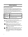
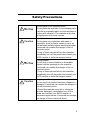
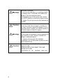
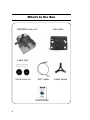
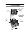
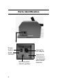
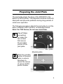
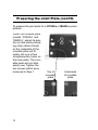
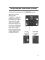
Quick Guide
For Rewinder:
RWG500
PN: 9001128 (B)
www.satoamerica.com
SATO America, Inc.
10350A Nations Ford Road
Charlotte, NC 28273
Main Phone: (704) 644.1650
Technical Support: (704) 644.1660
Technical Support Fax: (704) 644.1661
E-Mail: [email protected]
[email protected]
www.satoamerica.com
Copyright 2010 SATO America, Inc.
All rights reserved
Introduction
Thank you for your purchase of the SATO RWG500 new
generation rewinder for SATO barcode printers.
This quick reference guide will lead you on a familiarization tour to help you start using the machine as soon as
possible.
To get the most out of the RWG500’s intelligent features,
be sure to read this manual carefully before using the
machine.
Table of Contents
Introduction ...................................................1
Safety Symbols ............................................2
Safety Precautions .......................................3
FCC Notice ...................................................5
What’s In the Box .........................................6
Parts Identification ........................................7
Preparing the Joint Plate ..............................9
Adjusting the Roller Height............................13
Installing the Joint Plate ...............................14
Configuring the Rewinder..............................16
Label Setup ...................................................19
Basic Operation ............................................24
Winding 7” labels...........................................26
Installing the 7” Expansion Kit.......................27
Basic Specifications ......................................29
1
Safety Symbols
About warning symbols
As a preventive measure to ensure safe usage of this
machine so as to safeguard against damage to yourself,
other people or property, several symbols and icons are
used in this guide. The following pages describe the
significance of each symbol. Please take time to read and
understand the content.
If this display and its warning is ignored, any
mishandling could result in death or serious
injuries.
Caution
If this display and its warning is ignored, any
mishandling could result in serious injuries as
well as damage to properties.
Examples
The triangle sign means ‘Be careful’.
The content within the triangle illustrates specific
hazards. In this case, the sign on
the left means ‘beware of electric shock’.
The circular sign means ‘prohibited’. The
content within the circle illustrates a specific
prohibition. In this case the sign on the left means
‘disassembly prohibited’.
The black circular sign means ‘must do’. The
content within the sign illustrates specific items
that must be carried out. In this case the sign on
the left means ‘the plug must be unplugged from
the socket’.
2
Safety Precautions
Do not place on an unstable place
Do not place the rewinder on an unstable place
such as an unsteady table, an inclined place or
a place with vibration. The rewinder may drop
or topple over and cause injuries.
Caution
Liquids
Do not place any containers with water or
chemicals, such as flower vases or cups, as
well as small metallic objects near the rewinder.
Continued use creates the danger of fire or
electrical shock.
* If any of these should fall into the rewinder,
immediately turn off the power and contact your
SATO reseller or technical support center.
Foreign Matter
Do not drop or insert metallic or flammable
objects into the openings on the rewinder.
Continued use creates the danger of fire or
electrical shock.
* If any of these should fall into the rewinder,
immediately turn off the power and contact your
SATO reseller or technical support center.
Caution
Dropping and Damage
Do not use if the product has been dropped or
damaged. Continued use creates the danger of
fire and electrical shock.
* Should the rewinder ever fall or otherwise
become damaged, immediately turn off the
power and contact your SATO reseller or
technical support center. Continued use creates
the danger of fire or electrical shock.
3
Abnormal Conditions
Do not use the rewinder if it is emitting smoke
or strange odors. Continued use creates the
danger of fire and electrical shock.
* Immediately turn off the power and contact
your SATO reseller or technical support center
for repairs. Do not try to service the rewinder by
yourself.
Caution
Disassembly
Never try to take the unit apart or modify it in
any way. Doing so creates the danger of fire or
electrical shock. Contact your SATO reseller or
technical support center for repairs.
Location
Do not locate the rewinder in areas subjected to
high humidity or dew. Doing so creates the
danger of electrical shock.
* If moisture forms inside the rewinder,
immediately turn off the power and do not use it
until it has dried up.
Caution
4
FOR CONTINUED PROTECTION AGAINST
RISK OF FIRE.
REPLACE WITH THE SAME TYPE AND
RATING OF FUSE.
LOCATION : F1 , F2 RATING : 125V 3.5A
FCC Notice
The equipment referenced in this document complies with the requirements in
Part 15 of FCC Rules for a Class B Computing Device. Operation of this
equipment in a residential area may cause inacceptable interference to radio
and TV reception. If the interference is unacceptable, you can reposition the
equipment, which may improve reception.
5
What’s In the Box
RWG500 main unit
Joint plate
Label Clip
3-inch core x 2
EXT cable
Quick Guide
6
Label Guide
Parts Identification
Direction
Indicator LED:
Clockwise
winding
(face in)
Status
LED
Rewind
Start/Stop
button
Stopper
Plate
Direction
Indicator LED:
Counter-clockwise winding
(face out)
Second roller
First roller
Rewind
Core
Tension arm
7
Parts Identification
Power
Switch
Socket for
AC adaptor
Earth
terminal
EXT connector
(links to printer)
8
Selector for
clockwise or
counterclockwise rewind
direction
Preparing the Joint Plate
The joint plate aligns the base of the RWG500 to the
base of a SATO printer. This alignment ensures a smooth
label path and prevents problems during long periods of
continuous operation.
The following procedure adjusts the joint plate to suit the
base of different SATO printers, as described below.
Note: For TG3 Series, do not use Joint Plate.
1
Use a Phillips
screwdriver
to loosen the
two screws
that secure
the movable
portion of the
joint plate.
Main plate
2
Movable plate
Slide the movable
portion of the joint
plate in various
directions to
reveal the names
of various SATO
printer models.
9
Preparing the Joint Plate (cont’d)
To prepare the joint plate for a GT4XXe or M84Pro series
printers:
When the movable plate
reveals “GT4XXe” and
“M84Pro”, adjust its position so that each protruding stub (called a boss)
on the underside of the
movable plate will fit
neatly into one of two
complementary holes on
the main plate. The movable plate will not slide
easily now. Tighten the
two screws which were
loosened in Step 1.
Top of
movable
plate
Boss
10
Underside
of movable
plate
Boss
Preparing the Joint Plate (cont’d)
To prepare the joint plate for the M5900RVe printer:
When the movable
plate reveals
“M5900RVe”, adjust its
position so that each
protruding stub (called
a boss) on the underside of the movable
plate will fit neatly into
one of two complementary holes on the main
plate. The movable
plate will not slide easily now. Tighten the two
screws which were
loosened in Step 1.
Top of
movable
plate
Boss
Underside
of movable
plate
Boss
11
Preparing the Joint Plate (cont’d)
To prepare the joint plate for the CL6XXe series printers:
When the movable
plate reveals
“CL6XXe”, adjust its
position so that each
protruding stub (called
a boss) on the underside of the movable
plate will fit neatly into
one of two complementary holes on the main
plate. The movable
plate will not slide easily now. Tighten the two
screws which were
loosened in Step 1.
Top of
movable
plate
Boss
12
Underside
of movable
plate
Boss
Adjusting the Roller Height
Before the rewinder is guided into place in front of the
printer, the height of its first roller has to be adjusted to
one of two positions (upper or lower) to fit the printer.
Roller Height settings for SATO Printers
Model
Roller Height
GT4XXe
Lower position
CL6XXe
Lower position
CL4XXe
Upper position
M84Pro
Upper position
M5900RVe
Upper position
TG3 Series
Lower position
Roller in Upper
position
Install
two
locking
screws
here
Roller in lower
position
Install two locking screws here
13
Installing the Joint Plate
To align the printer to the RWG500 using the joint plate:
1
Place the non-movable
holes of the joint plate
under the feet of the
rewinder as shown. The
holes of the movable
plate should be facing
away from the rewinder.
2
Connect the Frame
Ground wire of the joint
plate to the Earth terminal on the rewinder.
Use a Phillips screwdriver if necessary.
Earthing completed
14
Installing the Joint Plate (cont’d)
3
Now place the printer
so that its feet at the
label output side will fit
into the positioning
holes on the joint place.
4
Make sure both the
printer and the rewinder
are turned OFF.
Locate the EXT connector of the printer and
use the supplied EXT
cable to connect the
printer to the rewinder’s
EXT connector.
Caution
Make sure that the
printer and rewinder are
aligned properly using
the joint plate. Otherwise rewinding errors
may occur.
15
Configuring the Rewinder
This section shows how to configure the label rewinder
for operation.
Choose the option identified below that best reflects the
desired effects. Then, refer to the table that follows, to
configure the label rewinder accordingly.
Rewind Mode 1
This is the standard operating mode as the rewinder is
delivered from the factory.
Rewind Mode 2
This rewinding mode synchronizes rewinder operation
with the feeding printer.
This setting allows the rewinder to cease operation when
paper-end or ribbon-end is detected on the assigned
printer.
Remains in a ready/standby state until the issue is
resolved.
16
Configuring the Rewinder (cont’d)
Rewind Mode 3
This rewinding mode synchronizes rewinder operation
with the feeding printer.
When the assigned printer goes offline, the label rewinder
also ceases operation. The preceding sentence also
applies to error conditions, as well as, paper-end and ribbon-end scenarios.
The printer can be switched between online and offline
modes by pressing the appropriate keys on the label
rewinder’s operator panel.
Program Download
This setting permits the firmware to be over-written with a
program downloaded from a host computer. To perform
this function, connect a RS232C interface cable between
the rewinder and a host computer. A connector is provided for this purpose.
The label rewinder must be powered off when setting the
DIP switches, and then power on to initialize.
17
Configuring the Rewinder (cont’d)
DIP SWITCH CONFIGURATION
FUNCTION
DSW
1
DSW
2
DSW
3
DSW
4
DSW
5
DSW
6
Rewind Mode 1
OFF
OFF
OFF
OFF
OFF
OFF
Rewind Mode 2
OFF
OFF
OFF
OFF
ON
OFF
Rewind Mode 3
ON
ON
OFF
OFF
ON
OFF
Program
Download Mode
X
X
X
X
X
ON
18
Label Setup
The RWG500 offers two rewind directions and two types
of rewind shafts, as follows:Rewinding Direction: Face in
(CW) / Face Out (CCRewinding Shaft: Direct rewind/3”
paper core rewind
About Rewinding Direction
Counterclockwise
winding (CCW)
In a CCW winding
direction, the printed
surface of the label is
always visible as it
faces outwards.
Clockwise
winding (CW)
In a CW winding direction,
the printed surface of the
label faces inwards and is
hidden from view. Only
the backing sheet (label
liner) faces outwards. The
rewind is set by default to
CW rewinding.
19
Label Setup (cont’d)
To change the rewind direction, use the Direction switch
found on the side panel of the rewinder. The factory setting is CW rewinding by default.
Setting Rewind Direction
1. Before changing the rewind direction, make sure
the rewinder is turned OFF, or make sure that the
Status LED is blinking in green (rewinder in Idling
state)
2. Locate the Direction switch at the side panel, and
set it to either CW (clockwise, face in) or CCW
(counterclockwise, face-out).
3. Check the control panel display to confirm that the
appropriate CW or CCW LED is lit.
Caution
Change the rewind direction only when the rewinder is in
an idling state, or when it is turned OFF.
20
Label Setup (cont’d)
Besides setting the rewind direction, you can set up the
rewinder for direct rewinding or rewinding using a 3”
paper core.
About Direct Rewinding
Use direct rewinding when a paper core is not to be
used, and the label being collected will not need
reprinting or reprocessing in future.
1
Set the rewinder for
CW or CCW rewind
direction and load
the label accordingly. Wind the label
at the rewinding
shaft, and insert the
provided label clip
to fasten the label
onto the shaft.
2
Now insert the label
guide. The label
output from the
printer is now set
for direct rewinding.
21
Label Setup (cont’d)
You can collect output labels onto a 3” paper core for
more consistent winding, and if the wound label needs to
be unwound later for reprocessing/reprinting.
Rewinding on a 3” paper core
1
If label width is
below 65 mm,
attach one of the
provided 3” core
adaptors to the
rewinding shaft.
Otherwise, use two
adaptors. The
adaptor(s) should
be inserted so that
the metal plate teeth faces in the same direction* as the rewind direction. Screw the adaptor(s) into the narrow groove of the shaft.
* For CW and CCW rewinding, the metal
teeth must face left or right respectively.
2
22
Space the adaptor(s)
along the shaft to fit
the label width, then
tighten each locking
screw. Make sure the
screw fits into the
metal nut sliding
along the groove.
Label Setup (cont’d)
After properly inserting the 3” core adaptor(s), follow the
steps below to install the label.
3
Insert the 3” paper
tube core into the
rewind shaft. Affix
the leading (front)
portion of the output
label to the paper
core with some
adhesive tape.
4
Finally, insert the
label guide.
Caution
Before installing any label, always make sure that
the rewinder is OFF, or in an idling state (Status
LED blinks green).
23
Basic Operation
After setting up the rewinder to work with your SATO
printer, rewinding can be performed.
1
Turn on the rewinder. Wait for the status LED on
the control panel to start blinking in green. The
rewinder is now in idling status–ready to collect
labels from the printer.
2
Press and hold down the
START/STOP button on the
rewinder control panel. The
rewind shaft starts rotating,
and the tension arm rises
and stops automatically.
This process takes up any
slack in the label path.
When the Status LED is lit
in green continuously,
release the Start/Stop button. The rewinder is now in
operation.
If you release the Start/Stop
button before the Status
LED lights up continuously
in green, repeat Step 1.
24
Basic Operation (cont’d)
3
Start the automatic rewinding by printing labels on
the printer. Each time a label is printed, the
rewinder automatically winds it outwards and
takes up any slack in the winding process.
4
When the rewinding is completed, press the
START/STOP button on the rewinder’s control
panel. The tension arm comes to rest and stops
automatically. The Status LED blinks in green to
signal the rewinder’s idling
status.
5
Remove the label on the printer, and then remove
the wound label on the rewinder. The wound label
can be removed easily because the tension arm is
inactive.
25
Winding 7” labels
To wind labels wider than 131 mm, the optional 7” Expansion Kit is required. The kit consists of the following:
1 Second roller joint
2 Second roller shaft guide
3 Core joint
4 Core shaft guide
26
Installing the 7” Expansion Kit
Follow the steps below to install the Expansion Kit.
1
Remove the cap
covering the
second roller of
the rewinder.
2
Insert the kit’s
second-roller
joint and second-roller shaft
guide. Tighten
the shaft guide
in a counterclockwise direction using a
screwdriver.
3
Reattach the
cap.
27
Installing the 7” Expansion Kit (cont’d)
4
1
Remove the cap
covering the
rewinding shaft
of the rewinder.
5
Insert the core
joint and core
shaft guide.
Tighten the shaft
guide in a counterclockwise
direction using a
screwdriver.
6
Reattach the cap
to complete
installation of the
expansion kit.
28
Basic Specifications
Rewinding
method
• Ø 38.1 mm direct rewinding
• 3” paper core rewinding
Paper type
Supports all genuine SATO labels printed on
SATO printers, except linerless labels
Paper width
Width: 25–131 mm (standard)
Width: 25–180 mm w/optional expansion kit.
Label thickness: 0.08–0.26 mm
Winding
direction
(selectable)
• Default setting: Face in (CW)
• Face out (CCW)
Note: Rewind direction must match the
winding direction of the label produced from
the printer.
Rewind
speed
Rewind
monitoring
Power
Supply
Auto speed setting, up to max of 381mm/s
Tension arm detects paper slack, paper
presence and incoming paper speed
DC25V
Power tapped from SATO
printer’s EXT port
External
diameter
Width (W) 280 mm
Depth (D) 320 mm
Height (H) 230 mm
Weight
7.5kg
29