1
Operating Manual (Edition 04/2004)
sinamics
AOP30 Operator Panel
SINAMICS G130
Contents
1.
Safety Information.......................................................................................................... 1-2
2.
General ............................................................................................................................ 2-6
3.
Mechanical Installation.................................................................................................. 3-7
4.
Connection ................................................................................................................... 4-10
5.
Control via the Operator Panel ................................................................................... 5-12
6.
Maintenance and Servicing......................................................................................... 6-31
7.
Technical Specifications ............................................................................................. 7-34
SINAMICS G130 - Operator Panel AOP30
Operating Manual
1-1
Safety Information
1.
Safety Information
1.1
Definitions and Warnings
04/04
Qualified Personnel
For the purpose of this documentation and the product warning labels, a “qualified
person” is someone who is familiar with the installation, mounting, start-up,
operation and maintenance of the product. He or she must have the following
qualifications:
• Trained or authorized to energize, de-energize, ground, and tag circuits and
equipment in accordance with established safety procedures.
• Trained in the proper care and use of protective equipment in accordance with
established safety procedures.
• First aid training.
DANGER
“Danger” indicates that death, severe personal injury, or substantial property
damage will result if proper precautions are not taken.
WARNING
“Warning” indicates that death, severe personal injury, or substantial property
damage can result if proper precautions are not taken.
CAUTION
“Caution” with a warning triangle indicates that minor personal injury can result if
proper precautions are not taken.
CAUTION
“Caution” without a warning triangle indicates that material damage can result if
proper precautions are not taken.
1-2
SINAMICS G130 - Operator Panel AOP30
Operating Manual
04/04
Safety Information
IMPORTANT
“Important” indicates that an unwanted result or situation can result if the
appropriate advice is not taken into account.
NOTE
“Note” indicates important information about the product or respective part of the
documentation that is essential to highlight.
WARNING
Hazardous voltages are present in this electrical equipment during operation.
Non-observance of the warnings can result in severe personal injury or property
damage.
Only qualified personnel should work on or around the equipment.
This personnel must be thoroughly familiar with all warning and maintenance
procedures described in this documentation.
The successful and safe operation of this device is dependent on correct transport,
proper storage and installation, as well as careful operation and maintenance.
National safety guidelines must be observed.
SINAMICS G130 - Operator Panel AOP30
Operating Manual
1-3
Safety Information
1.2
04/04
Safety and Operating Instructions
DANGER
This equipment is used in industrial high-voltage installations. During operation,
this equipment contains rotating and live, bare parts. For this reason, they could
cause severe injury or significant material damage if the required covers are
removed, if they are used or operated incorrectly, or have not been properly
maintained.
When the machines are used in non-industrial areas, the installation location must
be protected against unauthorized access (protective fencing, appropriate signs).
Prerequisites
Those responsible for protecting the plant must ensure the following:
• The basic planning work for the plant and the transport, assembly, installation,
commissioning, maintenance, and repair work is carried out by qualified
personnel and/or checked by experts responsible.
• The operating manual and machine documentation are always available.
• The technical data and specifications regarding the applicable installation,
connection, environmental, and operating conditions are always observed.
• The plant-specific assembly and safety guidelines are observed and personal
protection equipment is used.
• Unqualified personnel are forbidden from using these machines and working
near them.
This operating manual is intended for qualified personnel and only contain
information and notes relating to the intended purpose of the machines.
The operating manual and machine documentation are written in different
languages as specified in the delivery contracts.
NOTE
The services and support provided by the SIEMENS service centers are
recommended for planning, installation, commissioning, and servicing work.
1-4
SINAMICS G130 - Operator Panel AOP30
Operating Manual
04/04
Safety Information
Components that can be Destroyed by Electrostatic Discharge (ESD)
CAUTION
The board contains components that can be destroyed by electrostatic discharge.
These components can be easily destroyed if not handled properly. If you do have
to use electronic boards, however, please observe the following:
• You should only touch electronic boards if absolutely necessary.
• When you touch boards, however, your body must be electrically discharged
beforehand.
• Boards must not come into contact with highly insulating materials (such as
plastic parts, insulated desktops, articles of clothing manufactured from manmade fibers).
• Boards must only be placed on conductive surfaces.
• Boards and components should only be stored and transported in conductive
packaging (such as metalized plastic boxes or metal containers).
• If the packaging material is not conductive, the boards must be wrapped with a
conductive packaging material (such as conductive foam rubber or household
aluminum foil).
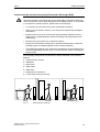
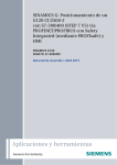
The necessary ESD protective measures are clearly illustrated in the following
diagram:
a = conductive floor surface
b = ESD table
c = ESD shoes
d = ESD overall
e = ESD chain
f = cabinet ground connection
g = contact with conductive flooring
d
d
b
b
e
e
f
g
a
c
f
f
c
Sitting
Fig. 1-1
d
Standing
a
f
f
g c
a
Standing/sitting
ESD protective measures
SINAMICS G130 - Operator Panel AOP30
Operating Manual
1-5
General
2.
04/04
General
Description
The user-friendly AOP30 operator panel is an optional input/output device for
SINAMICS G130 converters. The operator panel can be used for commissioning,
operation, and diagnostic purposes.
The AOP30 communicates with the SINAMICS drive via a serial interface (RS232)
with PPI protocol. The interface is a point-to-point connection. During
communication, the AOP30 is the master and the connected drive is the slave.
Structure
The AOP30 is an operator panel with a graphical display and a touch-sensitive
keypad. An RS232 interface is used as the interface to the drive unit. The device
can be installed in a cabinet door (thickness: between 2 mm and 4 mm).
Features
• Display with green backlighting (resolution: 240 x 64 pixels)
• 26-key touch-sensitive keypad
• Connection for a 24 V DC power supply
• RS232 interface
• Time and date memory powered by internal battery backup
• 4 LEDs indicate the operating status of the drive unit:
2-6
–
RUN: green
–
ALARM: yellow
–
FAULT: red
–
LOCAL/REMOTE: green
SINAMICS G130 - Operator Panel AOP30
Operating Manual
04/04
Mechanical Installation
3.
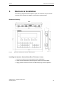
Mechanical Installation
The following diagrams and descriptions explain the conditions and procedures
involved in the mechanical installation of the AOP30 operator panel.
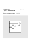
Dimension Drawing
197,5
156
212
Fig. 3-1
31
141,5
203
5,5
Dimension drawing of the AOP30 operator panel
Installing the Operator Panel (Cabinet Door Thickness: 2 mm)
1. Cut out a 141.5 mm x 197.5 mm section in the cabinet door.
2. Insert the AOP30 operator panel through this section from the outside.
3. Apply pressure to the four corners until the snap-in lugs lock into position.
SINAMICS G130 - Operator Panel AOP30
Operating Manual
3-7
Mechanical Installation
04/04
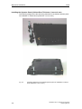
Installing the Operator Panel (Cabinet Door Thickness: 2 mm to 4 mm)
The following images show the tensioning elements for the AOP30 operator panel
for installation in cabinet doors (thickness: 2 mm to 4mm).
Fig. 3-2
3-8
Tensioning elements for the AOP30 operator panel for installation in cabinet
doors (thickness: 2 mm to 4mm)
SINAMICS G130 - Operator Panel AOP30
Operating Manual
04/04
Mechanical Installation
1. Cut out a 141.5 mm x 197.5 mm section in the cabinet door.
2. Insert the AOP30 operator panel through this section from the outside.
3. Hook the tensioning elements into the openings provided.
4. Tighten the screws by hand to secure the tensioning elements.
CAUTION
Make sure that the screws for the tensioning elements are not too tight,
otherwise the operator panel housing may be damaged.
SINAMICS G130 - Operator Panel AOP30
Operating Manual
3-9
Connection
4.
04/04
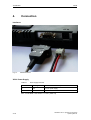
Connection
Interfaces
Fig. 4-1
AOP30 interfaces
X524: Power Supply
Table 4-1
Power supply terminals
Terminal
Designation
Technical specifications
+
P24
24 V DC power supply
M
M
Ground
Max. connectable cross-section: 2.5 mm² (AWG 12)
4-10
SINAMICS G130 - Operator Panel AOP30
Operating Manual
04/04
Connection
X540: Serial Interface (RS232)
Table 4-2
Serial interface (RS232) X540
Pin
Designation
Technical specifications
2
RxD
Receive data
3
TxD
Transmit data
5
Ground
Ground reference
Plug type: 9-pin SUB-D female
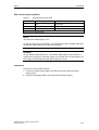
NOTE
The maximum cable length is 10 m.
To ensure noise-free communication, you are advised to use a shielded cable and
connect the cable shield to both connector housings.
CAUTION
On the operator panel electronics, a connected cable shield is connected to the
signal and P24 ground. If the power supply is connected with incorrect polarity, the
P24 supply via the shield and signal ground will short-circuit.
Connection
The AOP30 is connected as follows:
1. Connect the power supply cable to the interface for the electronics power
supply (X524).
2. Connect the standard cable to the serial RS232 interface (X540).
SINAMICS G130 - Operator Panel AOP30
Operating Manual
4-11
Control via the Operator Panel
04/04
5.
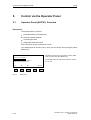
Control via the Operator Panel
5.1
Operator Panel (AOP30): Overview
Description
The operator panel is used for...
• Parameterization (commissioning)
• Monitoring status variables
• Controlling the drive
• Diagnosing faults and alarms
All the functions can be accessed via a menu.
Your starting point is the main menu, which you can always call up using the yellow
MENU key:
M a i n
m e n u
Operation display
Parameterization
Fault memory/alarm memory
Commissioning/Service
xxxxxxxxxxxxxxxxxxxxxxxxxxx
xxxxxxxxxxxxxxxxxxxxxxxxxxxxxxx
Help
F1
Fig. 5-1
5-12
F2
F3
F4
The dialog screen for the main menu can be called
up at any time using the "MENU" key.
To navigate within the main menu options, choose
"F2" or "F3".
Select.
F5
Main menu
SINAMICS G130 - Operator Panel AOP30
Operating Manual
04/04
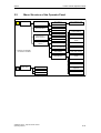
5.2
MENU
Control via the Operator Panel
Menu Structure of the Operator Panel
Main menu
Operation display
Act. Faults *)
List of previous faults
Act. Alarms *)
Parameterization
DO selection
All parameters
Control settings
Parameter groups...
Fault memory *)
Alarm memory *)
Commissioning /
Service
*) Help texts are available
for all alarms and faults
Faults
Display settings
Alarms
Define operating
screen
Drive commissioning
Set date/time
Device commissioning
Language switch
AOP settings
Reset AOP settings
AOP diagnosis
Software / database
version
Battery status
Communication
Safety locks
Operat. lock
Keyboard
Parameteriz. lock
Access level
Fig. 5-2
LED test
Menu structure of the operator panel
SINAMICS G130 - Operator Panel AOP30
Operating Manual
5-13
Control via the Operator Panel
5.3
04/04
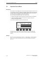
Operation Screen Menu
Description
The operation screen displays the most important status variables for the drive unit:
In its condition on delivery, it displays the operating status of the drive, the direction
of rotation, the time, as well as four drive variables (parameters) numerically and
two in the form of a bar display for continuous monitoring.
You can call up the operation screen in one of three ways:
1. After the power supply has been switched on and the system has ramped up.
2. If you do not make any entries for two minutes, the system calls up the
operation screen automatically.
3. By pressing the MENU key twice and then F5 "OK".
READY
NSET = 1450.000rpm
PACTV=
235.0kW
N_ACT[rpm ]
1450.0 0%
I_ACT[Aeff]
450.0 0%
F1
F2
F_OFF=
Udc =
12:25:30 S
50.0Hz
620.0V
50%
100%
50%
100%
F3
F4
F5
If a fault occurs, the system automatically displays the fault screen (see 5.8).
In LOCAL control mode, you can choose to enter the setpoint numerically (F2:
setpoint).
Settings
When you choose Commissioning / service –> AOP settings –> Define operation
screen, you can adjust the display type and the values displayed as required.
See 5.6.3
5-14
SINAMICS G130 - Operator Panel AOP30
Operating Manual
04/04
5.4
Control via the Operator Panel
Parameterization Menu
You can adjust the chassis unit settings in the parameterization menu.
The drive software is modular. The individual modules are called DO
("DriveObject").
The following DOs are available in the G130:
• CU
General parameters for the electronics module (CU320)
• Vector
Drive control
• TM31 (optional)
Terminal module TM31
Parameters with identical functions may exist with the same parameter number in
more than one DO (e.g. p0002 ).
The AOP30 is used for operating devices that comprise more than one drive (in
this respect, a regulated infeed is also a "drive") so that attention is focused on one
drive (i.e. the "current" drive). You can switch between the drives either in the
operation screen or in the main menu. The corresponding function key is labeled
"Drive".
This drive determines the following:
• Operation screen
• Fault and alarm displays
• Parameterization
Depending on your requirements, you can choose between two AOP display types:
1. All parameters
All the parameters for the current drive (see above), the CU, and all the other
device DOs are displayed in a list (as with older drives). The DO to which the
parameter currently selected belongs (inverted) is displayed in curly brackets in
the top left of the screen.
You can also select parameters for just one function group from this complete
list.
2. DO view
In this display, you can pre-select a DO so that only the parameters for this DO
are listed. This display is indicated by the text "DO" next to the DO designator in
curly brackets.
(The expert list in STARTER is only displayed in the DO view.)
In both cases, the set access level and the selected parameter group govern which
parameters are displayed. You can set the access level in the menu for inhibit
functions, which can be called up using the key button.
The parameters for access levels 1 and 2 are sufficient for simple applications. The
default setting is 1 Standard.
SINAMICS G130 - Operator Panel AOP30
Operating Manual
5-15
Control via the Operator Panel
04/04
At access level 3 (experts), you can change the structure of the function by
interconnecting BICO parameters. For this reason, this access level is password
protected (password: "47").
The parameter list displays more options than there are function keys. You can use
the "<<" key to change the function of the keys. To return from the second menu,
press F5 (">>"). Once a function is complete, the system automatically returns to
the main menu.
F1 "Help", F2 "DS Select", and F3 "EEPROM" are available in the extended menu.
In the DS Selection menu (data set selection), you can choose which of the data
sets chosen is currently DISPLAYED.
Data set parameters are indicated by a “c”, “d”, “m”, or “e” between the parameter
number and parameter designator. The second line from the top (aligned right)
shows which data sets are currently displayed.
5.5
Menu: Fault/Alarm Memory
Faults
Shows which faults are currently present (max.: 8).
To select one of the faults, choose F2. To call up a description of causes and
possible remedies, choose F1 "Help". The fault value, which allows more effective
diagnosis, is specified in the second line in Help.
To acknowledge the fault, choose F5 "Ack.". Once you have successfully
acknowledged the fault, the system returns to the calling screen. If the fault cannot
be acknowledged, the fault screen continues to be displayed.
To display the last eight faults, choose F3 "Old". The system then displays seven
acknowledged faults (1st – 7th fault).
Alarms
Displays the current content of the alarm buffer. Alarms present at the time the
screen was opened are displayed accordingly.
To refresh the display, choose F5: "Refresh". To delete the alarm buffer and rebuild
it so that it only contains the currently active alarms, choose F3 "Delete".
5-16
SINAMICS G130 - Operator Panel AOP30
Operating Manual
04/04
Control via the Operator Panel
5.6
Menu: Commissioning/Service
5.6.1
Drive Commissioning
This option enables you to re-commission the drive from the main menu.
5.6.2
Device Commissioning
In this menu, you can enter the device commissioning status directly. This is the
only way that you can reset parameters to the factory setting for example.
You can use this menu to create motor data sets in subsequent drive software
versions.
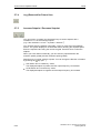
5.6.3
AOP30 Settings
Control Settings
This defines the settings for the control keys in LOCAL mode.
See 5.7.
Display Settings
In this menu, you set the lighting, brightness, and contrast for the display.
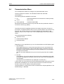
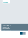
Defining the Operation Screen
In this menu, you can switch between four operation screens. You can set the
parameters that are to be displayed.
Define operating screen
xxxxxxxxxxxxxxxxxxxxxxxxxxxxxxxxxxxxx
Operating form Typ
4 values/2 bar
Operating form Valu
Form2 Type
10 values
Form2 Values
Form2 Not active
Help
Back
Change
F1
Fig. 5-3
F2
F3
F4
F5
F5
Operating form Values
xxxxxxxxxxxxxxxxxxxxxxxxxxxxxxxx
01:(63)r1114 NSOLL Setpt after limit
02:(63)r0024 F_AUS Output frequency
03:(63)r0032 PWIRK Output smoothed
04:(63)r0026 U_DC Vdc smoothed
xxxxxxxxxxxxxxxxxxxxxxxxxxxxxxxx
Help
Back
Change
F1
F2
F3
F4
F5
Defining the operation screen
SINAMICS G130 - Operator Panel AOP30
Operating Manual
5-17
Control via the Operator Panel
04/04
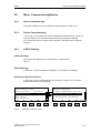
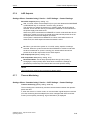
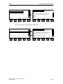
The following image shows how the entries are assigned to the screen positions:
OPERATION
Entry
Entry
Entry
Entry
Entry
12:25:30 S
01
03
05
07
09
Entry
Entry
Entry
Entry
Entry
OPERATION
Entry 01
Entry 03
Entry 05
02
04
06
08
10
12:25:30 S
Entry
Entry
Entry
Entry
0%
12:25:30 S
Entry 02
Entry 04
02
04
06
08
50%
OPERATION
Entry 01
100%
12:25:30 S
0%
50%
100%
0%
50%
100%
0%
50%
100%
Entry 02
0%
50%
100%
Entry 03
Entry 06
0%
Fig. 5-4
OPERATION
Entry 01
Entry 03
Entry 05
Entry 07
Entry 09
50%
100%
Position of the entries in the operation screen
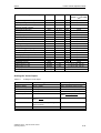
Lists of Signals for the Operation Screen
Vector Object
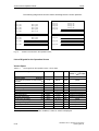
Table 5-1
List of signals for the operation screen –vector object
Signal
Parameters
Short name
Unit
Scaling
(100 % = ...), see Table
5-2
Speed setpoint upstream of ramp-function
generator
(1)
r1114
NSETP
1/min
p2000
Output frequency
r0024
F_OUT
Hz
Reference frequency
Factory setting
(entry no.)
(2)
Power smoothed
(3)
r0032
P_ACT
kW
r2004
DC link voltage smoothed
(4)
r0026
UDC
V
p2001
Actual speed smoothed
(5)
r0021
N_ACT
1/min
p2000
Absolute actual current smoothed
(6)
r0027
I_IST
A
p2002
Motor temperature
(7)
r0035 1
T_MOT
°C
Reference temperature
Converter temperature
(8)
r0037
T_LT
°C
Reference temperature
Actual torque smoothed
(9)
r0031
M_ACT
Nm
p2003
(10)
r0025
C_OUT
V
p2001
Speed setpoint smoothed
r0020
NSETP
1/min
p2000
Control factor smoothed
r0028
%
Reference control factor
Converter output voltage smoothed
For diagnostic purposes
1
If a temperature sensor has not been installed, a value of –200°C is displayed.
5-18
SINAMICS G130 - Operator Panel AOP30
Operating Manual
04/04
Control via the Operator Panel
Signal
Parameters
Short name
Unit
Scaling
(100 % = ...), see Table
5-2
A
p2002
Field-producing current component
r0029
Torque-producing current component
r0030
A
p2002
Converter overload
Degree of thermal overload
r0036
%
100 % = Shutdown
Speed setpoint after filter
r0062
N_ACT
1/min
p2000
Actual speed smoothed
r0063
N_ACT
1/min
p2000
Control deviation
r0064
1/min
p2000
Slip frequency
r0065
Hz
Reference frequency
Hz
Reference frequency
Output frequency
r0066
Output voltage
r0072
Control factor
r0074
UACT
V
p2001
%
Reference control factor
Torque-generating actual current
r0078
A
p2002
Actual torque value
r0080
Nm
p2003
Fixed speed setpoint effective
r1024
1/min
p2000
Active motor potentiometer setpoint
r1050
1/min
p2000
Resulting speed setpoint
r1119
1/min
p2000
Speed controller output
r1508
Nm
p2003
For further diagnostic purposes
I component of speed controller
r1482
Nm
p2003
PROFIBUS setpoint
r2050
1/min
p2000
Analog input 0 [V, mA]
r4052[0]
V, mA
V: 100 V / mA: 100 mA
Analog input 1 [V, mA]
r4052[1]
V, mA
V: 100 V / mA: 100 mA
Analog input 0, scaled
r4055[0]
%
V: 100 V / mA: 100 mA
Analog input 1, scaled
r4055[1]
%
V: 100 V / mA: 100 mA
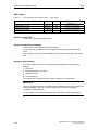
Scalings for Vector Object
Table 5-2
Scalings for vector object
Variable
Reference speed
Scaling parameter
Default for quick commissioning
100 % = p2000
p2000 = Maximum speed (p1082)
Reference voltage
100 % = p2001
p2001 = 1000 V
Reference current
100 % = p2002
p2002 = Current limit (p0640)
Reference torque
100 % = p2003
p2003 = 2 x rated motor torque
Reference power
100 % = r2004
Reference frequency
Reference control factor
100 % =
r2004 =
p2003 × p2000 × π
30
p2000
60
100 % = Maximum output voltage
without overload
Reference flux
100 % = Rated motor flux
Reference temperature
100% = 100 °C
SINAMICS G130 - Operator Panel AOP30
Operating Manual
5-19
Control via the Operator Panel
04/04
TM31 Object
Table 5-3
List of signals for the operation screen – TM31 object
Signal
Parameter
s
Unit
Scaling
(100 % = ...)
Analog input 0 [V, mA]
r4052[0]
V, mA
V: 100 V / mA: 100 mA
Analog input 1 [V, mA]
r4052[1]
V, mA
V: 100 V / mA: 100 mA
Analog input 0, scaled
r4055[0]
%
V: 100 V / mA: 100 mA
Analog input 1, scaled
r4055[1]
%
V: 100 V / mA: 100 mA
Setting the Date/Time
In this menu, you set the date and time.
Setting the Operating Language
In this menu, you can select the active language.
You have a choice between the two languages currently stored in the operator
panel.
If the language you require is not available, you can load it separately (see Section
6.2).
Resetting AOP Settings
This menu option allows you to reset the following settings to the AOP factory
settings:
• Language
• Display (brightness, contrast)
• Operation screen
• Control Settings
The settings are not effective until the power supply is next switched on.
IMPORTANT
When you reset parameters, all settings that are different to the factory settings are
reset immediately. This may cause the cabinet unit to switch to a different,
unwanted operational status.
For this reason, you should always take great care when resetting parameters.
5-20
SINAMICS G130 - Operator Panel AOP30
Operating Manual
04/04
5.6.4
Control via the Operator Panel
AOP30 Diagnosis
Software/Database Version
You can use this menu to display the firmware and database versions.
The database version must be compatible with the drive software status (you can
check this in parameter r0018).
Battery Status
In this menu, you can display the battery voltage numerically (in Volts) or as a bar
display. The battery ensures that the data in the database and the current time are
retained.
When the battery voltage is represented as a percentage, a battery voltage of ≤ 2 V
is equal to 0%, and a voltage of ≥ 3 V to 100%.
The data is secure up to a battery voltage of 2 V.
• If the battery voltage is ≤ 2.45 V, the message "Replace battery" is displayed in
the status bar.
• If the battery voltage is ≤ 2.30V, the system displays a popup window with the
following information "Warning: weak battery".
• If the battery voltage is ≤ 2 V, the system displays a popup window with the
following information: "Warning: battery is empty".
• If the time and/or database are not available after the system has been
switched off for a prolonged period due to the voltage being too low, the loss is
established by means of a CRC check when the system is switched on again.
This triggers a message instructing the user to replace the battery and then load
the database and/or set the time.
For instructions on changing the battery, see Section 6.1.
Communication
In this menu, you can call up information on the communications status between
the AOP and the drive.
Key Test
In this screen, you can check that the keys are functioning properly. Keys that you
press are represented on a symbolic keyboard on the display. You can press the
keys in any order you wish. You cannot exit the screen (F5 – "back") until you have
pressed each key at least once.
NOTE
You can also exit the key test screen by pressing any key and keeping it pressed.
LED Test
In this screen, you can check that the 4 LEDs are functioning properly.
SINAMICS G130 - Operator Panel AOP30
Operating Manual
5-21
Control via the Operator Panel
5.7
04/04
Operation via the Operator Panel (LOCAL Mode)
You activate the control keys by switching to LOCAL mode. If the green LED in the
LOCAL/REMOTE key does not light up, the key is not active.
5.7.1
LOCAL/REMOTE Key
Activate LOCAL mode: press the LOCAL key
LOCAL mode: LED lights up
REMOTE mode: LED does not light up: the ON, OFF, JOG, direction reversal,
faster, and slower keys are not active.
Settings: Menu: Commissioning / Service – AOP Settings – Control Settings
Save LOCAL mode (factory setting: yes)
• Yes: "LOCAL" or "REMOTE" operating mode is saved when the supply voltage
is switched off, and restored when the supply voltage is switched back on.
• No: "LOCAL" or "REMOTE" operating mode is not saved. "REMOTE" is active
when the supply voltage is switched back on.
LOCAL/REMOTE also during operation (factory setting: no)
• Yes: You can switch between LOCAL and REMOTE when the drive is switched
on (motor is running).
• No: Before the system switches to LOCAL, a check is carried out to determine
whether the drive is in the operational status. If so, the system does not switch
to LOCAL and outputs the message "Local not possible". Before the system
switches to REMOTE, the drive is switched off and the setpoint is set to 0.
5-22
SINAMICS G130 - Operator Panel AOP30
Operating Manual
04/04
5.7.2
Control via the Operator Panel
ON Key/OFF Key
ON key: always active in LOCAL when the operator input inhibit is deactivated.
OFF key: in the factory setting, acts as OFF1 = ramp-down at the deceleration
ramp (p1121); when n = 0: voltage disconnection (only if a main contactor is
installed).
The OFF key is only active in LOCAL mode.
Settings: Menu: Commissioning / Service – AOP Settings – Control Settings
Red OFF key acts as: (factory setting: OFF1)
• OFF1: Ramp-down on the deceleration ramp (p1121)
• OFF2: Immediate pulse block, motor coasts to a standstill
• OFF3: Ramp-down on the emergency stop ramp (p1135)
5.7.3
Switching Between Clockwise and Counter-Clockwise Rotation
Settings: Menu: Commissioning / Service – AOP Settings – Control Settings
Switching between CW/CCW (factory setting: no)
• Yes: Switching between CW/CCW rotation by means of the CW/CCW key
possible in LOCAL mode
• No: The CW/CCW key has no effect in LOCAL mode
For safety reasons, the CW/CCW key is disabled in the factory setting (pumps and
fans must normally only be operated in one direction).
In the operation status in LOCAL mode, the current direction of rotation is indicated
by an arrow next to the operating mode.
NOTE
You have to make additional settings when switching between CW/CCW rotation.
SINAMICS G130 - Operator Panel AOP30
Operating Manual
5-23
Control via the Operator Panel
5.7.4
Jog (Reserved for Future Use)
5.7.5
Increase Setpoint / Decrease Setpoint
04/04
You can use the “increase” and “decrease” keys to set the setpoint with a
resolution of 1 % of the maximum speed.
(e.g. if the resolution is 15 min-1 at p1082 = 1500 min-1)
You can also enter the setpoint numerically. To do so, press F2 in the operation
screen. The system displays an inverted edit field for entering the required speed.
Enter the required value using the numeric keypad. Press F5 OK to confirm the
setpoint.
When you enter values numerically, you can enter any speed between the
minimum speed (p1080) and the maximum speed (p1082).
Setpoint entry in LOCAL mode is unipolar. You can change the direction of rotation
key (see ).
by pressing the
• CW rotation and "Increase key" mean:
The displayed setpoint is positive and the output frequency is increased.
• CCW rotation and "Increase key" mean:
The displayed setpoint is negative and the output frequency is increased.
5-24
SINAMICS G130 - Operator Panel AOP30
Operating Manual
04/04
5.7.6
Control via the Operator Panel
AOP Setpoint
Settings: Menu: Commissioning / Service – AOP Settings – Control Settings
Save AOP setpoint (factory setting: no)
• Yes: In LOCAL mode, the last setpoint (once you have released the INCREASE
or DECREASE key or confirmed a numeric entry) is saved.
The next time you switch the system on in LOCAL mode, the saved value is
selected. This is also the case if you switched to REMOTE in the meantime or
the power supply was switched off.
When the system is switched from REMOTE to LOCAL mode while the drive is
switched on (motor is running), the actual value that was last present is set as
the output value for the AOP setpoint and saved.
If the system is switched from REMOTE to LOCAL mode while the drive is
switched off, the AOP setpoint that was last saved is used.
• No: When you switch the system on in LOCAL mode, setpoint 0 is always
selected. When the system is switched from REMOTE to LOCAL mode while
the drive is switched on (motor is running), the actual value that was last
present is set as the output value for the AOP setpoint.
AOP ramp-up time (factory setting: 20 s)
AOP ramp-down time (factory setting: 20 s)
• Recommendation: set as ramp-up/ramp-down time (p1120 / p1121).
Changing the ramp-up/ramp-down times does not affect the settings for
parameters p1120 and p1121 because this is an AOP-specific setting.
NOTE
The internal drive ramp-function generator is always active.
5.7.7
Timeout Monitoring
Settings: Menu: Commissioning / Service – AOP Settings – Control Settings
Timeout monitoring (factory setting: 3000 ms)
The monitoring time continuously monitors communication between the operator
panel and drive.
If, when the drive is in LOCAL mode, no communication signal has been received
once the monitoring time has elapsed, the drive is stopped with OFF1 and fault
F1030 ("control priority monitoring: sign-of-life failure") is displayed.
SINAMICS G130 - Operator Panel AOP30
Operating Manual
5-25
Control via the Operator Panel
5.7.8
04/04
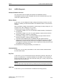
Operator Input Inhibit/Parameterization Inhibit
To prevent users from accidentally actuating the control keys and changing
parameters, you can activate an operator input / parameterization inhibit using a
key pushbutton. Two key icons appear in the top right of the display when these
inhibit functions are enabled.
Table 5-4
Display for operator input / parameterization inhibit
Inhibit type
No inhibit
Online operation
Offline operation
Operator input inhibit
Parameterization inhibit
Operator input inhibit +
parameterization inhibit
Settings
Operator input inhibit (factory setting: no)
• Yes: The parameters can still be viewed, but a parameter value cannot be
saved (message in the status bar: "Operator input inhibit – parameterization
disabled"). The OFF key (red) is enabled. The LOCAL, REMOTE, ON (green),
JOG, CW/CCW, INCREASE, and DECREASE keys are disabled.
Parameterization inhibit (factory setting: no)
• Yes: Parameters cannot be changed unless a password is entered. The
parameterization process is the same as with the operator input inhibit. If you try
and change parameters, the message "Parameterization inhibit – no change
rights" is displayed in the status bar. All the control keys can, however, still be
actuated.
NOTE
If you have forgotten your password, you can switch off the parameterization inhibit
as follows:
1. Switch off the power supply
2. Disconnect the RS232 data cable
3. When switching the power supply back on, press the key pushbutton and hold
down for 20 s.
4. When the key symbol in the top right of the display disappears, the access
protection function has been reset.
5-26
SINAMICS G130 - Operator Panel AOP30
Operating Manual
04/04
Control via the Operator Panel
Access level (standard factory setting):
The different parameters required for this complex application are filtered so that
they can be displayed as clearly as possible. You select them according to the
access level.
An expert level, which must only be used by expert personnel, is required for
certain actions. You need a password to activate this level. To activate expert
mode, enter code number "47".
The "Expert" access level is not stored permanently, which means that it must be
reactivated every time the power is switched on.
SINAMICS G130 - Operator Panel AOP30
Operating Manual
5-27
Control via the Operator Panel
5.8
04/04
Faults and Alarms
Indicating Faults and Alarms
If a fault occurs, the drive displays the fault and/or alarm on the operator panel.
Faults are indicated by the red "FAULT" LED and a fault screen is automatically
displayed. You can use the F1 Help function to call up information about the cause
of the fault and how to remedy it. You can use F5 Ack. to acknowledge a stored
fault.
Any alarms are displayed by the yellow "ALARM" LED. The system also displays a
note in the status bar providing information on the cause.
What is a Fault?
A fault is a message from the drive indicating an error or other exceptional
(unwanted) status. This could be caused by a fault within the converter or an
external fault triggered, for example, from the winding temperature monitor for the
asynchronous motor. The faults are displayed and can be reported to a higher-level
control system via PROFIBUS. In the factory default setting, the message
"converter fault" is also sent to a relay output. Once you have rectified the cause of
the fault, you have to acknowledge the fault message.
What is an Alarm?
An alarm is the response to a fault condition identified by the drive. It does not
result in the drive being switched off and does not have to be acknowledged.
Alarms are "self acknowledging", that is, they are reset automatically when the
cause of the alarm has been eliminated.
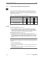
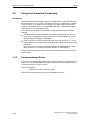
Fault and Alarm Displays
Every fault and alarm is entered in the fault/alarm buffer along with time the error
occurred and the time it was rectified. The time stamp relates to the relative system
time in milliseconds (r0969).
5-28
SINAMICS G130 - Operator Panel AOP30
Operating Manual
04/04
Control via the Operator Panel
Current fault in: 33463512
F7011 Drv: Motor Overtemp.
F1
Help
F1
Fig. 5-5
Old
F2
Back
F3
Ack.
F4
F5
Drv: Motor Overtemp.
Fault value: 00000000
00000000H
Cause:
Motor temperature has reached the
fault threshold parameterized in
(p0605).
Remedy:
Back
F1
F2
F3
F4
F5
Fault screen
You can use F5 Ack. to acknowledge a stored fault.
Alarm memory
A7850 External warning 1
A7910 Drv: Motor Overtemp.
A7852 External warning 3
Status
F1
active
F5
Help
F1
Fig. 5-6
F2
Delete
Back
upd.
F3
F4
F5
Drv: Motor Overtemp.
AlarmVal: 00000000
00000000(hex)
Cause:
Motor temperature has exceeded the
alarm threshold parameterized in
p0604.
The reaction set in p0610 is
Back
F1
F2
F3
F4
F5
Alarm screen
SINAMICS G130 - Operator Panel AOP30
Operating Manual
5-29
Control via the Operator Panel
5.9
04/04
Saving the Parameters Permanently
Description
If parameters have been changed using the operator panel (confirm with OK in the
Parameter Editor), the new values are initially stored in the volatile memory (RAM)
of the converter. An "S" flashes in the top right of the AOP display until they are
saved to a permanent memory. This indicates that at least 1 parameter has been
changed and not yet stored permanently.
Two methods are available for permanently saving parameters that have been
changed:
• The parameter list contains additional function key assignments. You can use
the "<<" key to change the function of the keys. In the extended menu, you can
save the data by choosing F3 "EEPROM".
• When confirming a parameter setting with OK, press the OK key for > 1 s. The
system displays a message asking you whether the setting is to be saved in the
EEPROM.
If you press "Yes", the system saves the setting in the EEPROM. If you press
"No", the setting is not saved permanently and the "S" starts flashing.
In both cases, all changes that have not yet been saved permanently are stored in
the EEPROM.
5.10
Parameterization Errors
If an error occurs while parameters are being read or written, this is indicated in the
status bar on the operator panel (the eighth or lowest line in the operation screen,
or the seventh line in all other screens).
The system displays:
Parameter write error (d)pxxxx.yy:0xnn
and a plain-text explanation of the type of parameterization error.
5-30
SINAMICS G130 - Operator Panel AOP30
Operating Manual
04/04
Maintenance and Servicing
6.
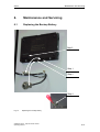
Maintenance and Servicing
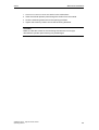
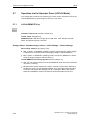
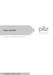
6.1
Replacing the Backup Battery
Step 3
Step 1
Step 2
Step 4
Fig. 6-1
Replacing the backup battery
SINAMICS G130 - Operator Panel AOP30
Operating Manual
6-31
Maintenance and Servicing
04/04
Replacing the Battery
1. Disconnect the 24 V DC power supply cable.
2. Disconnect the communication cable on the operator panel.
3. Open the cover of the battery compartment.
4. Remove the old battery.
5. Insert the new battery.
6. Carry out any other work by reversing the sequence.
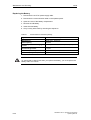
Table 6-1
Technical data for the backup battery
Type
CR2032 3V lithium battery
Manufacturer
Maxell, Sony, Panasonic
Rated capacity
220 mAh
Maximum permissible charging
current
10 mA (restricted to <2 mA in operator panel)
Self-discharge at 20°C
1 %/year
Service life (in backup mode)
> 1 year at 70°C; >1.5 years at 20 °C
Service life (in operation)
> 2 years
WARNING
To ensure that no data is lost when you replace the battery, you must replace the
battery within one minute.
6-32
SINAMICS G130 - Operator Panel AOP30
Operating Manual
04/04
6.2
Maintenance and Servicing
Load the New Operator Panel Firmware and Database
from the PC.
Description
You have to load the database for the operator panel each time you require a
language other than that stored in the operator panel, or if the chassis unit firmware
has been upgraded to a new version to improve performance or rectify problems.
The load program LOAD_AOP30 and the database files can be found on the CD.
Procedure for Loading the Database
1. Establish the RS232 connection from the PC to the AOP30.
2. Connect the 24 V power supply.
3. Start the LOAD_AOP30 program on the PC.
4. Choose the PC interface (COM1, COM2).
5. Depending on the language you require, choose a file (e.g.
AOP30_DB.V02.10.36.V01.03.02.E.D.CBIN) and open it to start loading the
database.
6. Once the firmware has been loaded, "Database loaded" is displayed on the
AOP30.
7. Switch the power on (switch the power supply off and then back on).
Procedure for Loading Firmware and the Database
1. Establish the RS232 connection from the PC to the AOP30.
2. Connect the 24 V power supply.
3. Start the LOAD_AOP30 program on the PC.
4. Choose the PC interface (COM1, COM2).
5. Choose and open the firmware (AOP30.H86).
6. Follow the instructions in the status window of the program and connect the
power supply for the AOP30 while pressing the red key (O).
7. The load procedure is started automatically.
8. If a current database has not been loaded, the system switches to the "loading
database" screen once the loading procedure has finished
9. Depending on the language you require, choose a file (e.g.
AOP30_DB.V02.10.36.V01.03.02.E.D.CBIN) and open it to start loading the
database.
10. Once the firmware has been loaded, "Database loaded" is displayed on the
AOP30.
11. Switch the power on (switch the power supply off and then back on).
SINAMICS G130 - Operator Panel AOP30
Operating Manual
6-33
Technical Specifications
04/04
7.
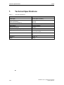
Technical Specifications
Table 7-1
Technical specifications
Power supply
24 V DC (20.4 V to 28.8 V)
Current requirements
- Without backlighting
- With maximum backlighting
<100 mA
<200 mA
Data interface
RS232 interface, PPI protocol
Backup battery
3 V lithium CR2032
Operating temperature
0 to 55°C
Temperature during storage/transportation
-25 to +70°C
Degree of protection
IP20 (inside cabinet)
IP55 (outside cabinet)
Certification
CULus
CE
Dimensions
See Fig. 3-1
Weight
0.55 kg
7-34
SINAMICS G130 - Operator Panel AOP30
Operating Manual
Siemens AG
Automation and Drives
Large Drives
P.O. Box 4743, D – 90025 Nuremberg
Germany
www.ad.siemens.de
© Siemens AG 2004
Subject to change without prior notice
Doc. no.: A5E00331451A
Printed in Germany