1
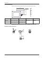
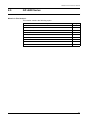
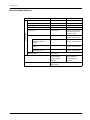
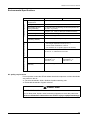
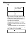
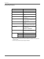
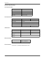
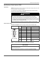
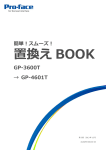
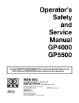
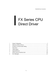
PFXGP4503TAD
http://www.axcontrol.com/automation/pro-face/gp-4000/PFXGP4503TAD
Pro-face Xycom GP4000
PFXGP4503TAD
Pro-face Xycom GP-450xT GP450xT
Touch Screen Operator Interface 10.4 TFT Analog Color LCD Display 24VDC UL/CE. Call Now!
1-800-991-7026
[email protected]
See Also:
http://www.axcontrol.com/automation/pro-face/gp-4000
Specifications
Panel Cut Dimensions
Create a panel cut and insert the GP unit into the opening from the front.
A
C
B
R
A
B
C
R
GP-4501T
GP-4503T
259 mm (+1, -0 mm)
(10.2 in. [+0.04, -0 in.])
201 mm (+1, -0 mm)
(7.91 in. [+0.04, -0 in.])
1.6...5 mm
(0.06...0.2 in.)
3 mm (0.12 in.)
maximum
GP-4501TW
301.5 mm (+1, -0 mm)
(11.87 in. [+0.04, -0 in.])
227.5 mm (+1, -0 mm)
(8.96 in. [+0.04, -0 in.])
NOTE: Before designing the panel cut, refer to Installation (see page 136).
Installation Fastener Dimensions
0
Ø1 .39
0
Ø
M6
12
0.47
mm
in.
12
0.47
26
1.02
116
14
0.55
GP4000 Series Hardware Manual
4.5
GP-4600 Series
What Is in This Section?
This section contains the following topics:
Topic
Page
Electrical Specifications
118
Environmental Specifications
119
Structural Specifications
120
Display Specifications
122
Memory, Clock, and Touch Panel
123
Interface Specifications
124
Specifications of Serial Interface COM1
125
Specifications of Serial Interface COM2
127
Dimensions
129
117
Specifications
Electrical Specifications
Power Supply
DC Model
Rated Input Voltage
24 Vdc
100...240 Vac
Input Voltage Limits
19.2...28.8 Vdc
85...264 Vac
Rated Frequency
-
50/60 Hz
Rated Frequency Range
-
47...63 Hz
Voltage Drop
10 ms or less
1 cycle or less (Voltage
drop interval must be 1
second or more)
Power Consumption
17 W or less
100 Vac: 44 VA or less
240 Vac: 58 VA or less
When power is not
supplied to external
devices
12 W or less
100 Vac: 30 VA or less
240 Vac: 44 VA or less
Backlight OFF (Standby
Mode)
7 W or less
100 Vac: 18 VA or less
240 Vac: 29 VA or less
Backlight Dimmed
(Brightness: 20%)
8 W or less
100 Vac: 22 VA or less
240 Vac: 31 VA or less
In-Rush Current
118
AC Model
30 A or less
1,500 Vac, 20 mA for 1
minute (between
charging and FG
terminals)
Voltage Endurance
1,000 Vac, 20 mA for 1
minute (between
charging and FG
terminals)
Insulation Resistance
500 Vdc, 10 MΩ or more (between charging and
FG terminals)
GP4000 Series Hardware Manual
Environmental Specifications
Electrical Environment Mechanical Environment
Physical Environment
DC Model
Surrounding Air
Temperature
0...55 °C (32...131 °F)
AC Model
Storage Temperature
-20...60 °C (-4...140 °F)
Surrounding Air and
Storage Humidity
10...90% RH (Non condensing, wet bulb temperature 39
°C [102.2 °F] or less)
Dust
0.1 mg/m3 (10-7 oz/ft3) or less (non-conductive levels)
Pollution Degree
For use in Pollution Degree 2 environment
Corrosive Gases
Free of corrosive gases
Atmospheric Pressure
(Operating Altitude)
800...1,114 hPa (2,000 m [6,561 ft] or lower)
Vibration Resistance
IEC/EN 61131-2 compliant
5...9 Hz Single amplitude 3.5 mm (0.14 in.)
9...150 Hz Fixed acceleration: 9.8 m/s2
X, Y, Z directions for 10 cycles (approx.100 minute)
Concussion Resistance
IEC/EN 61131-2 compliant
147 m/s2, X, Y, Z directions for 3 times
Noise Voltage: 1,500 Vp-p
Pulse Width: 1 µs
Rise Time: 1 ns
Noise Immunity
Noise Voltage: 1,000 Vp-p
Pulse Width: 1 µs
Rise Time: 1 ns
Electrostatic Discharge
Immunity
Contact Discharge Method: 6 kV (IEC/EN 61000-4-2 Level
3)
Air quality requirements
Do not operate or store the GP unit where chemicals evaporate, or where chemicals
are present in the air:
z
z
Corrosive chemicals: Acids, alkalines, liquids containing salt.
Flammable chemicals: Organic solvents.
CAUTION
INOPERATIVE EQUIPMENT
Do not allow water, liquids, metal, and wiring fragments to enter the panel case.
Failure to follow these instructions can result in injury or equipment damage.
119
Specifications
Structural Specifications
NOTE:
z If you are using the rear mount model, refer to Structural Specifications (see page
182).
Grounding
Functional grounding: Grounding resistance
of 100 Ω, 2 mm2 (AWG 14) or thicker wire,
or your country’s applicable standard.
(Same for FG and SG terminals)
Cooling Method
Natural air circulation
Structure*1
IP65F NEMA #250 TYPE 4X/13 (on the front
panel when properly installed in an
enclosure)
External Dimensions
W315 x H241 x D56 mm (W12.4 x H9.49 x
D2.2 in.)
Panel Cut Dimensions
W301.5 x H227.5 mm (W11.87 x H8.96
in.)*2
Panel thickness area: 1.6...5 mm (0.06...0.2
in.)*3
Weight
2.5 kg (5.5 lb) or less (main unit only)
NOTE: *1 The front face of the GP unit, installed in a solid panel, has been tested
using conditions equivalent to the standards shown in the specification. Even though
the GP unit’s level of resistance is equivalent to these standards, oils that should
have no effect on the GP unit can possibly harm the panel. This can occur in areas
where either vaporized oils are present, or where low viscosity cutting oils are
allowed to adhere to the GP unit for long periods of time. If the GP unit’s front face
protection sheet peels off, these conditions can lead to the ingress of oil into the GP
unit and separate protection measures are suggested.
Also, if non-approved oils are present, they may cause deformation or corrosion of
the front GP unit’s plastic cover. Therefore, prior to installing the GP unit, be sure to
confirm the type of conditions that will be present in the GP unit’s operating
environment. If the installation gasket is used for a long period of time, or if the GP
unit and its gasket are removed from the panel, the original level of protection cannot
be kept. To maintain the original protection level, be sure to replace the installation
gasket regularly.
*2
For dimensional tolerance, everything +1/-0 mm (+0.04/-0 in.) and R in angle are
below R3 (R0.12in.)
*3
Even if the installation wall thickness is within the recommended range for the
“Panel Cut Dimensions”, depending on wall’s material, size, and installation location
of the GP unit and other devices, the installation wall could warp. To prevent
warping, the installation surface may need to be strengthened.
CAUTION
EQUIPMENT DAMAGE
Ensure that the panel is not in permanent and direct contact with oils.
Failure to follow these instructions can result in injury or equipment damage.
120
GP4000 Series Hardware Manual
NOTICE
STORAGE AND OPERATION OUTSIDE OF SPECIFICATIONS
z
z
Store the panel in areas where temperatures are within the panel’s
specifications.
Do not restrict or block the panel’s rear-face ventilation slots.
Failure to follow these instructions can result in equipment damage.
NOTICE
GASKET AGING
z
z
Inspect the gasket periodically as required by your operating environment to
keep the initial IP level.
Change the gasket at least once a year, or as soon as scratches or dirt become
visible.
Failure to follow these instructions can result in equipment damage.
121
Specifications
Display Specifications
Display Type
TFT Color LCD
Display Size
12.1”
Resolution
800 x 600 pixels (SVGA)
Effective Display Area
W246.0 x H184.5 mm (W9.69 x H7.26
in.)
Display Colors
65,536 colors (No blink) / 16,384 colors
(Blink)
Backlight
White LED (Not user replaceable. When
replacement is required, contact your
local distributor.)
Backlight Service Life
50,000 hours (continuous operation at at
25 °C [77 °F] before backlight brightness
decreases to 50%)
Brightness Control
16 levels (Adjusted with touch panel or
software)
Language Fonts*1
Japanese, ASCII, Chinese (Simplified),
Chinese (Traditional), Korean, Cyrillic,
Thai
Character Sizes
Standard font: 8 x 8, 8 x 16, 16 x 16 and
32 x 32 pixel fonts
Stroke font: 6...127 pixel fonts
Image font: 8...72 pixel fonts
Font Sizes
Standard font: You can expand width up
to 8 times, and expand height up to 8
times.*2
Text
122
8 x 8 pixels
100 characters per row x 75 rows
8 x 16 pixels
100 characters per row x 37 rows
16 x 16 pixels
50 characters per row x 37 rows
32 x 32 pixels
25 characters per row x 18 rows
*1
Please refer to the GP-Pro EX Reference Manual for details on font types and
character codes.
*2
You can set up other font sizes using the software.
GP4000 Series Hardware Manual
Memory, Clock, and Touch Panel
Memory
Application Memory*1
FLASH EPROM 32 MB (including logic program area)
Logic Program Area
FLASH EPROM 132 KB (Equivalent to 15,000
steps)*2)
Font Area
FLASH EPROM 8 MB (when limit exceeded, uses
application memory)
Data Backup
SRAM 320 KB (Replaceable lithium battery for
backup memory)
Variable Area
SRAM 64 KB (Replaceable lithium battery for
retentive variables)
*1
Capacity available for user application (internal memory).
*2
Up to 60,000 steps can be converted in software. However, this reduces
application memory capacity for screen data by 1 MB.
Clock
± 65 seconds per month (deviation at room temperature and power is OFF).
Variations in operating conditions and battery life can cause clock deviations from 380 to +90 seconds per month.
For systems where this level of precision is insufficient, the user should monitor and
make adjustments when required.
Touch Panel
GP-4601T (Analog Touch
Panel) / GP-4603T
GP-4601T (Matrix Touch
Panel)
Touch Panel Type
Resistive Film (analog)
Resistive Film (matrix)
Touch Panel Resolution
1,024 x 1,024
40 x 30 keys/screen
Touch Panel Service Life
1 million times or more
123
Specifications
Interface Specifications
Serial Interface COM1
Asynchronous Transmission
RS-232C
Data Length
7 or 8 bits
Stop Bit
1 or 2 bits
Parity
None, odd or even
Data Transmission Speed
2,400...115,200 bps
Connector
D-Sub 9 pin (plug)
Serial Interface COM2
GP-4601T
GP-4603T
Asynchronous Transmission
RS-422 / RS-485
RS-485 (isolation)
Data Length
7 or 8 bits
Stop Bit
1 or 2 bits
Parity
None, odd or even
Data Transmission Speed
2,400...115,200 bps, 187,500 bps (MPI)
Connector
D-Sub 9 pin (plug)
D-Sub 9 pin (socket)
USB Interface
USB (Type A) Interface
Connector
USB 2.0 (Type A) x 1
USB 2.0 (mini-B) x 1
Power Supply Voltage
5 Vdc ±5%
-
Maximum Current
Supplied
500 mA
-
Maximum Transmission
Distance
5 m (16.4 ft)
Ethernet (LAN)
IEEE802.3i / IEEE802.3u,
10BASE-T/100BASE-TX
Connector
Modular jack (RJ45) x 1
Ethernet Interface
SD Card Interface
SD Card slot x 1 (maximum 32 GB SD/SDHC Card)
124
USB (mini-B) Interface
GP4000 Series Hardware Manual
Specifications of Serial Interface COM1
Introduction
NOTE: For instructions on how to connect to other devices, always refer to the “GPPro EX Device/PLC Connection Manual”.
The serial port is not isolated. The SG (signal ground) and FG (frame ground)
terminals are connected inside the GP unit.
DANGER
ELECTRIC SHOCK
When using the SG terminal to connect an external device to the panel:
z Verify that a short-circuit loop is not created when you set up the system.
z Connect the #5 SG terminal to remote equipment when the host (PLC) unit is
not isolated. Connect the #5 SG terminal to a known reliable ground connection
to reduce the risk of damaging the circuit.
Failure to follow these instructions will result in death or serious injury.
Serial Interface COM1
GP-4601T / GP-4603T: D-Sub 9 pin plug connector via an RS-232C cable.
Pin Connection
5
1
9
6
Pin
No.
RS-232C
Signal Name
Direction
Meaning
1
CD
Input
Carrier Detect
2
RD(RXD)
Input
Receive Data
3
SD(TXD)
Output
Send Data
4
ER(DTR)
Output
Data Terminal Ready
5
SG
-
Signal Ground
6
DR(DSR)
Input
Data Set Ready
7
RS(RTS)
Output
Request to Send
8
CS(CTS)
Input
Send possible
9
CI(RI)/VCC
Input/–
Called Status Display
(GP unit side)
+5V±5% Output 0.25A*1
Shell
FG
–
Frame Ground (Common
with SG)
NOTE: *1 You can switch pin #9 between RI and VCC via software.
NOTICE
EQUIPMENT DAMAGE
Use only the rated current.
Failure to follow these instructions can result in equipment damage.
125
Specifications
Interfit bracket is #4-40 (UNC).
Recommendations:
z Cable Connector: XM2D-0901 manufactured by OMRON Corporation.
z Cable Cover: XM2S-0913 manufactured by OMRON Corporation.
z Jack Screw (#4-40 UNC): XM2Z-0073 manufactured by OMRON Corporation.
CAUTION
LOSS OF COMMUNICATION
z
z
z
All connections to the communication ports must not put excessive stress on the
ports.
Securely attach communication cables to the panel wall or cabinet.
Use only D-Sub 9 pin cables with a locking tab in good condition.
Failure to follow these instructions can result in injury or equipment damage.
126