1
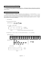
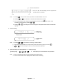
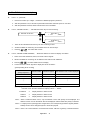
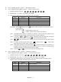
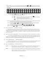
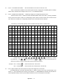
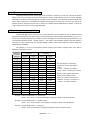
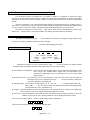
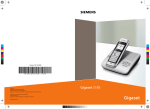
Appendix I FBs-DAP Simple HMI In addition to timer, counter, register, and contact data access function, the date setter of FBs-DAP can connect to many others for alarm message display, self-defined special keys, wireless card reading(RFID), and the like simple human machine interface(HMI) functions. FBs-DAP / FB-DAP Simple HMI Model *FB-DAP-A(R/W) FBs-DAP-B(R) FBs-DAP-C(R) FBE FBE /FBs FBs Specifications Matching PLC series Display LCD (English), 2-line×16 characters, LED backlight Button 20 keys (4×5) Wireless card reading(RFID) Power input Available only in −AR, -AW Available only in -BR, -CR 5V 24V 5V 100mA(120mA) 41mA(48mA) 105mA(125mA) Communication interface HCMOS (5V) RS485 RS232 Number of linked station Single Maximum 16 stations Single Current consumption General functions Timing/counting、register、contact access(write protected for each) Special functions Alert, message display, self-defined special keys Writing function(RFID) Model -AW is required Available in -BR, -CR * The card number of CARD-2 can be changed by the special model FB-DAP-AW. RFID card Model CARD-1 CARD-2 *CARD-H FB-DAP-R/W FB-DAP-R/W FBs-DAP-BR/CR 134.2KHz 134.2KHz 13.56MHz Specifications Matching DAP models Operating frequency Memory 64bits with Cyclic Redundancy Check (CRC) on data −25°C~50°C (ISO7810) Working temperature Power supply Sensing distance Writing times Battery not required (power supplied from wireless electric waves released by card-reading module −AR/−BR/-CR) 12cm~18cm Unwritable(cannot copy, unique) Dimensions (mm) Weight (Gram) 5cm~9cm At least 10000 times 86×54×13 12 5 CARD-H includes one set of read-only UID code (unique card number that cannot be duplicated) and another set of ID code (card number) available for writing/reading. FBs-DAP-BR/-CR can select to read either set of card numbers. Appendix I -1 1.1 Profile 4ψ×4 DATA ACCESS PANEL FBs-DAP Lateral Back Front FATEK X T 7 A M 1 F ADR / DOC B DEC / HEX 0 FUN CLEAR 6 2 3 CV / PV W S R 9 5 4 D ON / OFF 8 E Y C + SHIFT ENTER 1.2 Important points before operation 1、 FBs-DAP possesses a function to return to the operation mode (general data setter and self-defined 8/16 special keys) before power failure and each DAP can be place in a different mode when connecting many sets. 2、 When operating FBs-DAP,D2944~D3071 register of PLC will be used as the system configuration area (most data set by FUN functions are stored here) , the user shall avoid this area. 3、 Any communication port, once converted to a RS485 interface, can be connected to a maximum of 16 FBs-DAP-B(R) sets. 4、 When PLC is connected with FBs-DAP-B(R),the station number of PLC is limited to a range of 1~32. 5、 The communication parameter of connections between PLC and FBs-DAP-B(R) are: port0、1、2:9600 / 19200 / 38400、Even、7 Data bits、1 Stop bit (DAP automatic detection baud rate 9600 / 19200 / 38400) ex:R4158=5521H, i.e. port2 being 9600;R4158=5523H, i.e. port2 being 38400. 6、 When many sets of DAP are connected, if any two or more have the same station number, then DAP will request for number change, which can be done by only entering〝 new DAP NO. ” keys。 7、 The transmission line of the RS-485 interface must use a twisted pair with a shielded cover on the outer layer. Please refer to chapter 11 in the Operation Manual II for other important points. 8、 The scanning time of PLC will affect the update time of DAP. 9、 When Proladder(or FP-08) and DAP are connected to the same set of PLC, to change the program through Proladder is not allowed; if so, the timer information displayed by DAP won’t be correct (In this case, the DAP shall be reset). 10、FP-08 is capable of entry of common with up to 16 characters for contacts and registers editing. Appendix I -2 1.3 The main functions of FBs-DAP The main functions of FBs-DAP can be categorized as: general data accessing, FUN functions of parameter setting, wireless card reading (RFID), and message display function. The details of the functions will be introduced in the following sections. 1.4 General data access function FBs-DAP can be used as a 〝TC setter〞as well as the access to registers (R、D、W) and contacts (X、Y、M、S). In the FUN functions in the following sections, it can also be used as write-protect with T、C、R、D、X、Y、M、S. There are two kinds of display for monitoring information: ADR (general addresses) and DOC monitoring. The latter shall make DOC compilation (max. 16 words in English, symbols, numbers) in advance through Proladder or FP-08 for T, C, register R/D and contacts so the DOC can be displayed. 1、 ADR monitoring A. Timer and Counter monitoring 【Pressing keys】: T or C number or number Cursor position ↓ ↑ Status ← Set value ← Current value ↑ FBs-DAP automatic detecting a decimal point position B. Registers (R、D、DR、DD、WX、WY、WM、WS) and contacts (X、Y、M、S) monitoring 【Monitored range】 Type T C D R DD DR WX WY WM WS X Y M S Range 0 | 255 0 | 255 0 | 4095 0 | 8071 0 | 4094 0 | 8070 0 | 240 0 | 240 0 | 1984 0 | 984 0 | 255 0 | 255 0 | 2001 0 | 999 【Pressing keys】: or +( + ( ) or number ( or Cursor position ↓ or or or or or ) Value ↓ ← Item 1 ← Item 2 ↑ Status Appendix I -3 ) + 〝H〞 indicates hexadecimal ↓ ↑ Y15 ※ WX、WY、WM、WS can display one item only but each pressing status is available. ↑ Y0 Note:1、Pressing 2、Pressing can move the cursor up and down or switch between CV or PV. or can decrease or increase the monitored item number. 3、For a monitored item value, input a new value directly and then press + contacts can be changed by pressing 4、Pressing + . The status of the . can change the means to display a value (either with decimal or hexadecimal system). 2、 DOC monitoring ← DOC of T10 ← Current value ↑ Contact status Note:1、Pressing + ← Register DOC ← Value can switch the monitoring of ADR and DOC. 2、The display switch between CV (current value) and PV of the timer (counter) can use 3、 or . can be moved up or down to next monitored item with DOC. 3、 Speed monitoring FUN keys(FUN KEY 0~9, totaling 10 keys) 【Pressing keys】: + ( ~ ) B Direct display of a monitored item set by the client. Note:1、Items to be monitored can be set from the following “FUN functions”. 2、Items to be monitored can be displayed with ADR or DOC monitoring. Appendix I -4 1.5 FUN Functions 1.5.1 In and out of FUN functions ■ Enter FUN functions + Press + OR 1、PASSWORD OPEN (Password open) 2、PASSWORD CLOSE (Password blocked) 3、PASSWORD SET (Password setting) 4、DEFINE FUN KEY (Self-defined function keys for fast monitoring) 5、DEFINE ALARM ADDRESS (Define the start address of content for display at an alarm) 6、DEFINE SOFTKEY (8-KEY) (Self-defined 8 soft keys) * 7、ENTER SOFTKEY MODE (8-KEY) 8、DEFINE SOFTKEY (16-KEY) * 9、ENTER SOFTKEY MODE(16-KEY) ○ ○ ○ ○ ○ (Enter the 16 soft keys mode) (Adjust volume) 11、SET DAP NO. (Set DAP NO. for multi-link) 12、MAX. DAP NO. ON NETWORK(1~16) (Set the max. DAP numbers(1-16) on network for multi-link) 13、WRITE PROTECT (Data write-in protection) 14、RF CARD MODE (RF card mode selection) 15、RF CARD START ADDR. (Set the start address to store the ID code of RF card) KEYS MAPPING 17、DAP ASSIGN. FOR 8/16-KEY (Enable keys mapping to corresponding special contacts) (8/16 soft keys mode assignment for each DAP ) * 18、SELECT ID CODE OF RF CARD * (Self-defined 16 soft keys) 10、VOLUME * 16、ENABLE ○ (Enter the 8 soft keys mode) 19、WRITE RF CARD * 20、LOCK R/W ID CODE OF RF CARD (Select the ID code category of RF card) (Write new ID code into RF card) (Lock the ID code of RF card) *:Indicates when multiple DAPs are connected, each DAP can be set respectively. ○ :Indicates when multiple DAPs are connected, the information set by one of them is not available for use until PLC is reset. ■ Exit of FUN functions to general data access functions. Press + + Monitored items + Note:1、When several DAPs are connected, information can be stored to PLC (D2944~D3071) if one of the DAP is set in all the FUN functions (except item 11). 2、After entering FUN 4~20, without password protection, all the FUN functions can be executed by only pressing . With password protection, it is required to pass it first before executing FUN functions. 3、If it is password-protected, FBs-DAP will be set in a password protection status at each beginning of operation. 4、FUN items 1~9 can be entered with numeric keys directly and then go straight to that function. 5 、 After executing a item of FUN functions, if execution of other items is required, press the three keys + + again. Appendix I -5 1.5.2 FUN function description FUN 1~3(password) 1、 Password contains up to 4 digits(unrelated to LADDER program’s password). 2、 After the password is set, it will enter a password-locked status until DAP power on next time. 3、 After the password is locked, all the FUN functions are not available. FUN 4(DEFINE FUN KEY):Self-defined function keys for fast monitoring. FUN KEY 0 > T 10 〈 ADR〉 4、 DEFINE FUN KEY … 、 FUN KEY 9 > R1000 〈 DOC〉 1、 There are ten self-defined function keys for fast monitoring in total. 2、 All items available for monitoring can be defined in the ten function keys. 3、 Pressing + can select ADR or DOC. FUN 5(DEFINE ALARM ADDRESS):Define the address of content for display at an alarm. 1. There are ten start addresses, that is, ten levels of alarm signals. 2. All items available for monitoring can be defined in the said ten start addresses. 3. Pressing 4. Control measures of alarm signals for display are shown as follows: + can select ADR or DOC for display. 【Corresponding list for control】 Alarm level (priority sequence) Control contact Indication register Start address of the content displayed ALARM 0 M1900 R3820 Client-defined ALARM 1 M1901 R3821 Client-defined R3829 …… M1909 …… …… …… ALARM 9 Client-defined 【Example】Assume the start address of ALARM 0 displayed content to be R100, If M1900=1 then the alarm address for display is R100 +(R3820) If R3820=0 Display address or DOC of R100 R3820=1 Display address or DOC of R101 R3820=2 Display address or DOC of R102 Note 1:When a multi-level alarm occurs, only the address or DOC with priority can be displayed. The address or DOC of a sub level alarm will not be displayed until this alarm with priority is released. Note 2:To display a DOC (message) with 16 digits above, the corresponding indication register (R3820~ R3829) content can be changed anytime to reach this purpose. Note 3:M1911 can control whether to sound the alarm buzzer. If M1911=0 (preset), it shall be activated. Appendix I -6 FUN 6(DEFINE SOFTKEY-8 KEYS):Self-defined 8 soft keys FUN 7(ENTER SOFTKEY MODE-8 KEYS):Enter the 8 soft key mode 、 、 、 、 、 、 1. Available for defining 8 soft keys: 2. Definable range:R0~R3839、D0~D2943、M0~M1899. 3. In defining M0~M1899, this key can be defined as one of the 5 modes. Mode Definition 、 Description Set (S) Set this contact to 1 1 Reset (R) Set this contact to 0 2 Moment (M) 1 in pressing, 0 in being released 3 Inverse (I) Pressing once will have one inverse phase. Monitor (V) Monitor this contact 0 4 【Example】 Assume definition as R0, definition as M0 mode 0(Set). Once enter the 8 soft key mode in function 7, Then pressing display address or DOC of R0. display address or DOC of M0 and force M0 ON Note 1:After defining the 8 soft keys, once function 7 is executed, it will enter 8 soft key operation mode. And then the 8 soft keys will be executed according to function 6 definitions. and Note 2:In situation of with no definition, push either of them will cause DAP returning the general data access function. Just push 、 Note 3: to turn back 8/16 soft keys mode. both are allowed out of definition, but the other keys will not be effected without definition. +(D2972 content)+ Note 4:To return to normal operation mode, press〝 D2972 content is from 0000~9999(4 digits required). Note 5:When define special key, for optional can push 〞, among which and choose protection or non-protection on the defined content. (the upper right corner of LCD show that " p " content of monitoring which shows this special key can only be read and can't be written) Note 6:Push both and at one time can transform 8/16 soft keys mode. FUN 8(DEFINE SOFTKEY-16 KEYS):Self-defined 16 soft keys FUN 9(ENTER SOFTKEY MODE-16 KEYS):Enter the16 soft keys mode 、 、 、 、 、 、 ~ 1. Available for defining 16 soft keys: 2. Definable range:T0~T255、C0~C199、R0~R3839、D0~D2943、M0~M1899。 3. In defining M0~M1899, this key can be defined as one of the 5 modes and when a message is being displayed, if the key is pressed, the display will not be changed. Mode Definition Description 0 Set (S) 1 Reset (R) Set this contact to 0 2 Moment (M) 1 in pressing, 0 in being released 3 Inverse (I) Pressing once will have one inverse phase. 4 Monitor (V) Monitor this contact Set this contact to 1 Appendix I -7 4. When defined as T, C, R or D, the value change is by pressing or to make the corresponding M1840~M1871 ON (the client is required to write a plus/minus 1 program in the LADDER program) to achieve this purpose. Soft key 0 1 2 3 4 5 6 7 8 9 T C D R SHIFT M1840 M1841 M1842 M1843 M1844 M1845 M1846 M1847 M1848 M1849 M1850 M1851 M1852 M1853 M1854 M1855 M1856 M1857 M1858 M1859 M1860 M1861 M1862 M1863 M1864 M1865 M1866 M1867 M1868 M1869 M1870 M1871 【Example】Assume definition as R0, defined as M0 mode 1 (Reset). After entering 16 soft key mode in function 9, Display the address or DOC of R0, and then pressing Press , its corresponding M1850 will be ON; OFF after it is released. Display the address or DOC of M0 and force M0 OFF. Note 1:After the 16 soft keys are defined, once function 9 is executed, it will enter 16 soft key operation mode and then the 16 soft keys will be executed according to function 8 definition. Note 2:In situation of and with no definition, push either of them will cause DAP returning the general data access function. Just push to turn back 8/16 soft keys mode. Note 3:To return to normal operation mode, press〝 Note 4:Push both and +( + + + )+ 〞. at one time can transform 8/16 soft keys mode. FUN 11(SET DAP NO.):Set DAP NO. for multi-link. After any communication of FBs-PLC is converted to RS485 interface (Among which port2 as such is a RS485 interface), the FBs-DAP-B(R) of the 16 sets can be connected. Each DAP shall need a unique number, 1~16 (but one of them must be number 1). This DAP is not related to PLC numbers, meaning the number can have the same PLC number. FUN 12(MAX. DAP NO. ON NETWORK):Set the max. DAP numbers on network for multi-link. (Max. 16 ,default 7) In a connection of several DAPs, FBs-PLC can be joined with new DAPs. But the more the DAP number, the longer the time to update information of each DAP. As a result, set the DAP number (the DAP number can not be bigger than this number) on network appropriately will decrease time for information to update. FUN 13(WRITE PROTECT):Data write-in protection Aimed for monitored items (T, C, R, D, Y, M, S), set the information in write-in protection separately. Just fill in the corresponding place with 1, and then the item is write-in protected and can be read values only. FUN 14(RF CARD MODE):RF card mode selection MODE=〝0〞 When reading a RF card, it will display whether this card is OK or Error. When the RF card is out of sensing distance, it will pop up 〝NEXT〞, indicating another RF card is available now. MODE=〝1〞 Once a RF card is read, it will beep once and will not display any information so the sensing speed can be faster. But when many DAPs are connected, this mode will increase by about 60mS to each set for monitored item information. Appendix I -8 FUN 15(RF CARD START ADDR.):Set the start address to store the ID code of RF card Store a card number’s address can be set through the function, ranging from D0~D2860 (preset to D2860). Please refer to “Wireless card reading functions in sec. 1.6” for detailed description. FUN 16(ENABLE KEYS MAPPING):Enable keys mapping to corresponding special contact After this function is set to 〝Enable〞and enter SOFTKEY MODE(8-KEY and 16-KEY), pressing a definable soft key will force ON some contact of a corresponding contact under its number and the other contacts become OFF. When set to “Disable”, the corresponding special contact of this DAP will not be effected. The following is corresponding special contacts to different DAP keys when in 16-KEY mode: KEY No. T C D R 7 4 (↑) (↓) 1 0 8 5 2 SHIFT 9 6 3 1 M1784 M1785 M1786 M1787 M1788 M1789 M1790 M1791 M1792 M1793 M1794 M1795 M1796 M1797 M1798 M1799 2 M1768 M1769 M1770 M1771 M1772 M1773 M1774 M1775 M1776 M1777 M1778 M1779 M1780 M1781 M1782 M1783 3 M1752 M1753 M1754 M1755 M1756 M1757 M1758 M1759 M1760 M1761 M1762 M1763 M1764 M1765 M1766 M1767 4 M1736 M1737 M1738 M1739 M1740 M1741 M1742 M1743 M1744 M1745 M1746 M1747 M1748 M1749 M1750 M1751 5 M1720 M1721 M1722 M1723 M1724 M1725 M1726 M1727 M1728 M1729 M1730 M1731 M1732 M1733 M1734 M1735 6 M1704 M1705 M1706 M1707 M1708 M1709 M1710 M1711 M1712 M1713 M1714 M1715 M1716 M1717 M1718 M1719 7 M1688 M1689 M1690 M1691 M1692 M1693 M1694 M1695 M1696 M1697 M1698 M1699 M1700 M1701 M1702 M1703 8 M1672 M1673 M1674 M1675 M1676 M1677 M1678 M1679 M1680 M1681 M1682 M1683 M1684 M1685 M1686 M1687 9 M1656 M1657 M1658 M1659 M1660 M1661 M1662 M1663 M1664 M1665 M1666 M1667 M1668 M1669 M1670 M1671 10 M1640 M1641 M1642 M1643 M1644 M1645 M1646 M1647 M1648 M1649 M1650 M1651 M1652 M1653 M1654 M1655 11 M1624 M1625 M1626 M1627 M1628 M1629 M1630 M1631 M1632 M1633 M1634 M1635 M1636 M1637 M1638 M1639 12 M1608 M1609 M1610 M1611 M1612 M1613 M1614 M1615 M1616 M1617 M1618 M1619 M1620 M1621 M1622 M1623 13 M1592 M1593 M1594 M1595 M1596 M1597 M1598 M1599 M1600 M1601 M1602 M1603 M1604 M1605 M1606 M1607 14 M1576 M1577 M1578 M1579 M1580 M1581 M1582 M1583 M1584 M1585 M1586 M1587 M1588 M1589 M1590 M1591 15 M1560 M1561 M1562 M1563 M1564 M1565 M1566 M1567 M1568 M1569 M1570 M1571 M1572 M1573 M1574 M1575 16 M1544 M1545 M1546 M1547 M1548 M1549 M1550 M1551 M1552 M1553 M1554 M1555 M1556 M1557 M1558 M1559 In 8-KEY mode, only 8 keys keys ineffective. And 、 、 、 、 take the positions of 、 、 、 and 、 are effective, i.e. number , but it must be when both keys are defined as soft keys so that the corresponding special contacts are effective. 〈Example〉 No.2:Pressing No. 5:Pressing , M1768 is ON and M1769~M1783 OFF. , M1722 is ON and other contacts M1720~M1735 OFF. FUN 17 (DAP ASSIGN. FOR 8/16-KEY):8/16 soft keys mode assignment for each DAP. As multiple DAPs are connected, if this DAP select “0)SAME”, as long as one of the connected DAPs(also selects〝0〞)sets it self-defined 8/16 soft keys can be shared. If “1)INDEPENDENT”is selected, then this DAP can have independent settings which may have different definitions of its 8/16 soft keys than other DAPs. Appendix I -9 FUN18 (SELECT ID CODE OF RF CARD): Select the ID code category of RF card. RF CARD-H contains one set of 16-code (0~F) UID code (unique card number, safe from duplication) and one set of 12-code (0~F) writable/readale ID code(card number), which can be used to select the ID code to read from FBs-DAP. FUN19 (WRITE RF CARD): Write new ID code into RF card Please read section 1.6 for details. FUN20 (LOCK R/W ID CODE OF RF CARD): Lock the ID code of RF card RF CARD-H contains one set of 12-code (0~F) writable/readable ID code. Upon execution of this function, the ID code cannot be written as a new set of card numbers. 1.6 Wireless card(RFID) read/write functions RF CARD-H that suits FBs-DAP contains one set of 16-code (0~F) UID code (unique card number, safe from duplication) and one set of 12-code (0~F) writable/readable ID code (card number). All card numbers read in by FBs-DAP are coded for protection with high security. The sensing distance of CARD-H generally ranges from 5~9cm, away from sources of electromagnetic waves or great power lines. There are two ways to write the ID code(card number) into RF CARD-H (but can’t lock R/W ID code): 1 Use FUN19 of FBs-DAP: In FUN 19, input 12 numbers from 0~F or use In the end place CARD-H within 5 cm from FBs-DAP and press 、 to change the card number. to write the card number into CARD-H. 2 Use the PLC ladder program : Please firstly set M1899 and M1910 to “ON” status and store new card number in D2940~D2942 through PLC ladder program. When put CARD-H inside the sensing distance,FBs-DAP will store the new number in CARD-H within 150mS (when the scan time of PLC is longer than 100mS, this time will increase accordingly) and display “OK” to indicate the completion of card number writing. Locations and application of the card number storage FBs-DAP saves RF card numbers within sensing distance into two places in PLC. The places and application are described as follows: 1、Fixed in R3835~R3839(totaling 5 registers):During operation, M1910 shall be controlled. Card number format R3835 N1 N2 N1:DAP number 1~16(i.e. 1H~10H) R3836 ×××× N2:52H(R:read-only card) or 57H(W:readable/writable card) R3837 ×××× R3836~R3839 store 16 0~F card numbers R3838 ×××× R3839 ×××× Application: Only in monitoring (or8/16 soft keys) mode (non-FUN functions) and the RF card in sensing distance, FBs-DAP(−BR or −CR)will send the RF card number together with DAP number to PLC R3835~R3839. In mode 0 of function 14 (RF CARD MODE), all the client needs to do is compare the card number. If it is OK, only set M1910 to 1 and then DAP will indicate “OK”, or “ERROR”. When the RF card is out of sensing distance, DAP will pop up “NEXT” and clear the content of PLC R3838~R3839 to 0, which means available for another RF card. In mode 1 of function 14, as soon as DAP reads a card number, it will save it to R3835~R3839 with a beep. After the RF card exits, the 5 registers remain unchanged. Appendix I -10 Applicable occasions: Where one set or multiple sets are connected but RF cards are not used frequently, the program to be applied will be a lot easier. But in the event of a card number read from different DAPs at the same time, it will be difficult for PLC to identify the information correctly. 2、Preset D2860~D2939 (16 differently-located DAP take on 5 registers individually, i.e. 80 registers in all, but the locations can be changed through function 15) control one point of M1880~M1895 separately when in use. Card number format D2860 N1 N2 Card number format D2865 N1 N2 Card number format D2870 N1 N2 D2861 ×××× D2866 ×××× D2871 ×××× D2862 ×××× D2867 ×××× D2872 ×××× D2863 ×××× D2868 ×××× D2873 ×××× D2864 ×××× D2869 ×××× D3974 ×××× No. 1 ⇓ M1880 No. 2 ⇓ M1881 Card number format No. 3 ⇓ M1882 D2935 ……….. N1 N2 D2936 ×××× D2937 ×××× D2938 ×××× D2939 ×××× No. 16 ⇓ M1895 Application measures: The application measures are all described as the above-mentioned but that the storage places of card numbers and corresponding contacts for control are different. For example, in mode 0 of function 14, from No. 2 DAP sensing to the RF card, now no. 2 will send same card numbers to two different places in R3835~R3839 and D2865~D2869 (the content of the other registers remains unchanged), and all the client needs to do is control M1881 for the DAP to display “OK” or “ERROR”. After the RF card exits, the content of the 10 registers R3835 ~ R3839 and D2865 ~ D2869 will be cleared to 0 (but remains unchanged in mode 1). Applicable occasions: When several DAPs are connected, the RF card can be read in from different DAPs and each DAP has its independent card numbers storage places and control points so that no PLC misjudgment case occurs, but the programming will be more troublesome. ※ If you do not want R3835~R3839 to display a card number value, you can use the Ladder program to fill in these registers with other fixed values. Appendix I -11 1.7 Special message display function In general monitoring mode and soft key mode (16 KEYS or 8 KEYS), the user can configure the DAP to display every kind of message under some circumstances, and the two-line display on the LCD can be controlled separately to simultaneously display different messages. Every message is 1~511 words and numbers (ASCII code) long, in which a maximum of 16 variables (if variables with 32-digit are not used, then it can use up to 25) can be included. When a message has more than 16 words, the message will be displaced left for display, in which the moving speed or pause time can be configured flexibly. 1.7.1 Message display application The FBs-DAP-B(R) can be connected up to 16 sets (Number 1~16). Each DAP not only can display different messages individually but make all the DAPs connected display the same message simultaneously. If you go to a special contact (R3780~M3813) set by Enable, the DAP will display the message ASCII Code) indicated by the corresponding indication register (R3780~M3813). The content of the indication register is the start register of messages, i.e. start of ASCII Code. The indication register content can be changed anytime in order to change and display different messages. The following is a list of corresponding special contacts and indication registers when each DAP is displaying a message for control. Number of a message LCD line 1 LCD line 2 displayed Special contact Indication register Special contact Indication register 1~16 M1800 R3780 M1801 R3781 1 M1802 R3782 M1803 R3783 2 M1804 R3784 M1805 R3785 3 M1806 R3786 M1807 R3787 4 M1808 R3788 M1809 R3789 5 M1810 R3790 M1811 R3791 6 M1812 R3792 M1813 R3793 7 M1814 R3794 M1815 R3795 8 M1816 R3796 M1817 R3797 9 M1818 R3798 M1819 R3799 10 M1820 R3800 M1821 R3801 11 M1822 R3802 M1823 R3803 12 M1824 R3804 M1825 R3805 13 M1826 R3806 M1827 R3807 14 M1828 R3808 M1829 R3809 15 M1830 R3810 M1831 R3811 16 M1832 R3812 M1833 R3813 ※ The start register of a message indicated by an indication register means: 0~8070:indicating R0~R8070 10000~13070:indicating D0~D3070 ※ Special contacts M1800 and M1801 have a priority display function. ※ M1911 can control an alarm buzzer whether to sound or not. If M1911=0 (preset), it shall be activated. 〈Example〉Assume M1803 from 0→1, R3783=100 Result:Line 2 of No. 1 of the LCD will display messages in ASCII Code with R100 start. 〈Example〉 Assume M1828 from 0→1, R3808=10000 Result:Line 1 of No. 14 of the LCD will display messages in ASCII Code with D0 start. 〈Example〉 Assume M1801 from 0→1, R3781=0 Result:Line 2 of all the DAPs will display messages in ASCII Code with R0 start. Appendix I -12 1.7.2 The Information formats of messages(ASCII) The information formats of messages are very similar to chapter 14 “Application of ASCII File Output Function” in the Advanced Manual that are all categorized as fixed background information and dynamic variable information. The first can be words in English, numbers, or signs, and the second binary, decimal or hexadecimal system. Length of a message is 1~511 digits (including blank spaces), but because there are only 16 digits a line in a DAP LCD, if a message has more than 16 digits, it will be displayed automatically toward the left (preset moving one time a second); if less than 16 digits, the tail will be filled in with blank digits and no moving occurs. The editing of message can work through 「ASCII Table」function under WinProladder by choose ”DAP output” from 「Output preview」then start the editing. The editing command formats are as follows: 1 Background information format Any ASCII Code digits quoted with ' ' can be background information. To display a single quotation mark as such, two continuous quotation marks are a must. Example: ' I ' 'M A BOY' will be displayed I'M A BOY 2 Variable information format ,"8 .2 ↗ ↑ Total variable count displayed Decimal point count R0 ↑ D", ↖ Variable Register Carry code displayed Description information in a pair of dual quotation marks 〝 〞is used to indicate the register address (number) storing the variable information and in what format and carry code to display. Total variable count displayed:In this case, the value (including minus) of the variable R0 is displayed in a field with 8 digits. If the variable value is bigger than the total variable count displayed, the digits further from the point will be cut. If not enough, blank spaces will fill in. Decimal point count:the decimal point count in the total digits. In this case, with a total count of 8 digits, the decimal point count is 2. The decimal point sign 〝.〞 as such possesses one digit and there are 5 digits left in the integral part. Variable register:can be used as 16 digit register’s R、D、WX、WY、………, or 32 digit register’s DR、DD、 DWX、DWY、………etc. The content value in the register will be retrieved and displayed with the format and carry code described in the 〝 〞. Contacts:generally displayed as ON or OFF (total digit count displayed is set to a fixed 3), but if added with binary system B in the tail, 0/1 will be displayed (total digit count fixed 1) Carry code:can be hexadecimal H, decimal D (the carry code will use decimal if without indication, so D can be omitted.), or binary B, etc., but a 32 digit variable can not be displayed with binary system. In this case, R0’s content value is −32768. In 8.2 format the result is displayed as: − 3 2 7 . 6 8 If the format is changed from 8.2 to 5.1, then the result becomes: 2 7 6 . 8 Appendix I -13 3 Basic command signs nS Left move speed (repeatable) Message displayed at a left LCD move per n(1~255)× 0.1s。 nP Stop move (repeatable) Message stop in(1~255)× 0.1s,and then move left at a configured speed. , Comma Used as a statement to divide the file information. Information between two neighboring commas is a complete and executable statement (unnecessary for the start and end of a file). END End of a file ※ nS and nP commands will not be activated until after the information following them moves to the left first place on the LCD display. They can have a repeatable arrangement of any place in ASCII, but the same command cannot be connected together. 〈Example〉 Information edited with WinProladder ASCII file editor. R0 is a start register of an ASCII file and the file information is shown as follows: 5S,20P,’A=’,〝6.2R3840〞,’B=’,〝6.2R3841〞,30P,’C: ’ D: ’,〝1M1B〞,’ E: ’,〝1M2B〞, ’ ’,〝1M0B〞, ’,END If M1800 from 0→1 and R3780=0(i.e. R0), Line 1 of the LCD of DAPs of all numbers is shown as follows: Move a place left after stopping 2 seconds Move a place left per 0.5s After stopping 3s and then move a place left Return to display again after reaching the end of the ASCII ※ Variable information is renewable anytime. ※ To display another message, just change R3780 value and not for M1800. Appendix I -14 Always displayed in a cycle ︵ when M1800 And R3780 Are Not changed ︶