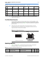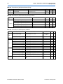
1
EthernetBlaster Communications Cable
User Guide
101 Innovation Drive
San Jose, CA 95134
www.altera.com
Software Version:
Document Version:
Document Date:
80
1.1
July 2008
Copyright © 2008 Altera Corporation. All rights reserved. Altera, The Programmable Solutions Company, the stylized Altera logo, specific device designations, and all other
words and logos that are identified as trademarks and/or service marks are, unless noted otherwise, the trademarks and service marks of Altera Corporation in the U.S. and other
countries. All other product or service names are the property of their respective holders. Altera products are protected under numerous U.S. and foreign patents and pending applications, maskwork rights, and copyrights. Altera warrants performance of its semiconductor products to current specifications in accordance with Altera's standard warranty,
but reserves the right to make changes to any products and services at any time without notice. Altera assumes no responsibility or liability arising out of the application or use of
any information, product, or service described herein except as expressly agreed to in writing by Altera Corporation. Altera customers are advised to obtain the latest version of
device specifications before relying on any published information and before placing orders for products or services.
UG-120904-1.1
P25-10326-01
Contents
Chapter 1. About the EthernetBlaster Communications Cable
Introduction . . . . . . . . . . . . . . . . . . . . . . . . . . . . . . . . . . . . . . . . . . . . . . . . . . . . . . . . . . . . . . . . . . . . . . . . . . . . 1–1
Supported Devices . . . . . . . . . . . . . . . . . . . . . . . . . . . . . . . . . . . . . . . . . . . . . . . . . . . . . . . . . . . . . . . . . . . . 1–1
Power Requirements . . . . . . . . . . . . . . . . . . . . . . . . . . . . . . . . . . . . . . . . . . . . . . . . . . . . . . . . . . . . . . . . . . 1–1
Software Requirements . . . . . . . . . . . . . . . . . . . . . . . . . . . . . . . . . . . . . . . . . . . . . . . . . . . . . . . . . . . . . . . . 1–2
Connections . . . . . . . . . . . . . . . . . . . . . . . . . . . . . . . . . . . . . . . . . . . . . . . . . . . . . . . . . . . . . . . . . . . . . . . . . . 1–2
Static & Dynamic IP Addressing . . . . . . . . . . . . . . . . . . . . . . . . . . . . . . . . . . . . . . . . . . . . . . . . . . . . . . . . 1–3
Cable Setup . . . . . . . . . . . . . . . . . . . . . . . . . . . . . . . . . . . . . . . . . . . . . . . . . . . . . . . . . . . . . . . . . . . . . . . . . . . . . 1–4
Remote Connection via Network Using Default Factory Settings . . . . . . . . . . . . . . . . . . . . . . . . . . . . 1–4
Direct Connection to a Computer Using Default Factory Settings . . . . . . . . . . . . . . . . . . . . . . . . . . . . 1–7
Configuring the EthernetBlaster Hardware to Use Static IP Addressing . . . . . . . . . . . . . . . . . . . . . 1–10
Configuring the EthernetBlaster Hardware to Use Dynamic IP Addressing . . . . . . . . . . . . . . . . . . 1–11
Setting Up the EthernetBlaster Hardware in the Quartus II Software . . . . . . . . . . . . . . . . . . . . . . . . 1–12
Removing the EthernetBlaster Hardware from the Quartus II Software . . . . . . . . . . . . . . . . . . . . . . 1–13
Chapter 2. EthernetBlaster Communications Cable Administration
Introduction . . . . . . . . . . . . . . . . . . . . . . . . . . . . . . . . . . . . . . . . . . . . . . . . . . . . . . . . . . . . . . . . . . . . . . . . . . . . 2–1
Managing Passwords . . . . . . . . . . . . . . . . . . . . . . . . . . . . . . . . . . . . . . . . . . . . . . . . . . . . . . . . . . . . . . . . . . . . 2–1
Changing the Administrative Password . . . . . . . . . . . . . . . . . . . . . . . . . . . . . . . . . . . . . . . . . . . . . . . . . . 2–1
Changing the Quartus II Remote Connection Password . . . . . . . . . . . . . . . . . . . . . . . . . . . . . . . . . . . . 2–2
Resetting the Hardware . . . . . . . . . . . . . . . . . . . . . . . . . . . . . . . . . . . . . . . . . . . . . . . . . . . . . . . . . . . . . . . . . . 2–3
Firmware Upgrade . . . . . . . . . . . . . . . . . . . . . . . . . . . . . . . . . . . . . . . . . . . . . . . . . . . . . . . . . . . . . . . . . . . . . . 2–4
Chapter 3. EthernetBlaster Communications Cable Specifications
Overview . . . . . . . . . . . . . . . . . . . . . . . . . . . . . . . . . . . . . . . . . . . . . . . . . . . . . . . . . . . . . . . . . . . . . . . . . . . . . . 3–1
EthernetBlaster Hardware Connections . . . . . . . . . . . . . . . . . . . . . . . . . . . . . . . . . . . . . . . . . . . . . . . . . . . . 3–1
Voltage Requirements . . . . . . . . . . . . . . . . . . . . . . . . . . . . . . . . . . . . . . . . . . . . . . . . . . . . . . . . . . . . . . . . . 3–1
EthernetBlaster Ethernet Jack Connection . . . . . . . . . . . . . . . . . . . . . . . . . . . . . . . . . . . . . . . . . . . . . . . . 3–2
EthernetBlaster Plug Connection . . . . . . . . . . . . . . . . . . . . . . . . . . . . . . . . . . . . . . . . . . . . . . . . . . . . . . . . 3–2
Circuit Board Header Connection . . . . . . . . . . . . . . . . . . . . . . . . . . . . . . . . . . . . . . . . . . . . . . . . . . . . . . . 3–3
Operating Conditions . . . . . . . . . . . . . . . . . . . . . . . . . . . . . . . . . . . . . . . . . . . . . . . . . . . . . . . . . . . . . . . . . . . . 3–3
Chapter Info. Additional Information
Referenced Documents . . . . . . . . . . . . . . . . . . . . . . . . . . . . . . . . . . . . . . . . . . . . . . . . . . . . . . . . . . . . . . . .
Revision History . . . . . . . . . . . . . . . . . . . . . . . . . . . . . . . . . . . . . . . . . . . . . . . . . . . . . . . . . . . . . . . . . . . . .
How to Contact Altera . . . . . . . . . . . . . . . . . . . . . . . . . . . . . . . . . . . . . . . . . . . . . . . . . . . . . . . . . . . . . . . .
Typographic Conventions . . . . . . . . . . . . . . . . . . . . . . . . . . . . . . . . . . . . . . . . . . . . . . . . . . . . . . . . . . . . .
© July 2008
Altera Corporation
Info–1
Info–2
Info–2
Info–2
EthernetBlaster Communications Cable User Guide
iv
EthernetBlaster Communications Cable User Guide
© July 2008 Altera Corporation
List of Figures
v
List of Figures
Figure 1–1: EthernetBlaster Communications Cable Ethernet Port, Target Port, and Base Views . . . . . . 1-3
Figure 1–2: Remote Connection via Network . . . . . . . . . . . . . . . . . . . . . . . . . . . . . . . . . . . . . . . . . . . . . . . . . . 1-5
Figure 1–3: Connecting the EthernetBlaster Communications Cable to the Target Circuit Board . . . . . . 1-5
Figure 1–4: MAC Address & Host Name . . . . . . . . . . . . . . . . . . . . . . . . . . . . . . . . . . . . . . . . . . . . . . . . . . . . . . 1-6
Figure 1–5: EthernetBlaster Configuration Administrative Page . . . . . . . . . . . . . . . . . . . . . . . . . . . . . . . . . . 1-7
Figure 1–6: Direct Connection to a Computer Using a Crossover Cable . . . . . . . . . . . . . . . . . . . . . . . . . . . . 1-8
Figure 1–7: Direct Connection to a Computer Using a Standard Cable and a Crossover Adapter . . . . . . 1-9
Figure 1–8: EthernetBlaster Change Settings Page . . . . . . . . . . . . . . . . . . . . . . . . . . . . . . . . . . . . . . . . . . . . . 1-10
Figure 1–9: EthernetBlaster Change Settings Page . . . . . . . . . . . . . . . . . . . . . . . . . . . . . . . . . . . . . . . . . . . . . 1-11
Figure 1–10: Hardware Setup Dialog Box . . . . . . . . . . . . . . . . . . . . . . . . . . . . . . . . . . . . . . . . . . . . . . . . . . . . 1-12
Figure 2–1: Change Admin Password Page . . . . . . . . . . . . . . . . . . . . . . . . . . . . . . . . . . . . . . . . . . . . . . . . . . . . 2-2
Figure 2–2: Change Quartus II Remote Connection Password Page . . . . . . . . . . . . . . . . . . . . . . . . . . . . . . . 2-3
Figure 2–3: Machine Reset button . . . . . . . . . . . . . . . . . . . . . . . . . . . . . . . . . . . . . . . . . . . . . . . . . . . . . . . . . . . . 2-3
Figure 2–4: Upgrade Firmware Page . . . . . . . . . . . . . . . . . . . . . . . . . . . . . . . . . . . . . . . . . . . . . . . . . . . . . . . . . . 2-5
Figure 3–1: Ethernet Jack Pin Number Designations . . . . . . . . . . . . . . . . . . . . . . . . . . . . . . . . . . . . . . . . . . . . 3-2
Figure 3–2: EthernetBlaseter 10-Pin Female Target-Side Plug Dimensions . . . . . . . . . . . . . . . . . . . . . . . . . 3-2
Figure 3–3: 10-Pin Male Header Dimensions . . . . . . . . . . . . . . . . . . . . . . . . . . . . . . . . . . . . . . . . . . . . . . . . . . . 3-3
© July 2008
Altera Corporation
EthernetBlaster Communications Cable User Guide
vi
EthernetBlaster Communications Cable User Guide
List of Figures
© July 2008 Altera Corporation
List of Tables
vii
List of Tables
Table 1–1: Status LED Modes . . . . . . . . . . . . . . . . . . . . . . . . . . . . . . . . . . . . . . . . . . . . . . . . . . . . . . . . . . . . . . . . 1-3
Table 1–2: Programming Modes . . . . . . . . . . . . . . . . . . . . . . . . . . . . . . . . . . . . . . . . . . . . . . . . . . . . . . . . . . . . 1-13
Table 2–1: Default Factory Settings . . . . . . . . . . . . . . . . . . . . . . . . . . . . . . . . . . . . . . . . . . . . . . . . . . . . . . . . . . . 2-3
Table 3–1: EthernetBlaster VCC(TRGT) Pin Voltage Requirements . . . . . . . . . . . . . . . . . . . . . . . . . . . . . . . . 3-1
Table 3–2: EthernetBlaster Female Plug Signal Names & Programming Modes . . . . . . . . . . . . . . . . . . . . . 3-2
Table 3–3: EthernetBlaster Cable Absolute Maximum Ratings . . . . . . . . . . . . . . . . . . . . . . . . . . . . . . . . . . . . 3-3
Table 3–4: EthernetBlaster Cable Recommended Operating Conditions . . . . . . . . . . . . . . . . . . . . . . . . . . . 3-4
Table 3–5: EthernetBlaster Cable DC Operating Conditions . . . . . . . . . . . . . . . . . . . . . . . . . . . . . . . . . . . . . . 3-4
© July 2008
Altera Corporation
EthernetBlaster Communications Cable User Guide
viii
EthernetBlaster Communications Cable User Guide
List of Tables
© July 2008 Altera Corporation
1. About the EthernetBlaster
Communications Cable
Introduction
The EthernetBlaster communications cable connects to a standard Ethernet network
port with an RJ-45 connector. This cable communicates with client systems using the
TCP/IP protocol and supports both static and dynamic IP addressing. The
EthernetBlaster communications cable can be plugged into an existing 10/100 Base-T
Ethernet network to communicate with clients remotely or interfaced directly via a
standard 10/100 Base-T Ethernet port using a crossover cable. Because design
changes are downloaded directly to the device, prototyping is easy and you can
accomplish multiple design iterations in quick succession. Harnessing the power of
an Ethernet network, multiple users can remotely access Altera® devices, bringing a
new level of productivity to prototyping and debugging.
Supported Devices
You can use the EthernetBlaster communications cable to download configuration
data to the following Altera devices:
■
Stratix® series FPGAs
■
Cyclone® series FPGAs
■
MAX® series CPLDs
■
APEX™ series FPGAs
■
ACEX® 1K FPGAs
■
Mercury™ FPGAs
■
FLEX® series FPGAs
■
Excalibur™ FPGAs
You can perform in-system programming of the following devices:
■
Advanced configuration devices, including EPC2, EPC4, EPC8, and EPC16
devices.
■
Serial configuration devices, including EPCS1, EPCS4, EPCS16, EPCS64 and
EPCS128 devices.
In addition, the EthernetBlaster communications cable supports target systems using
5.0-V TTL, 3.3-V LVTTL/LVCMOS, and single-ended I/O standards from 3.3 V down
to 1.5 V.
Power Requirements
The EthernetBlaster communications cable requires between 1.5 V and 5.0 V from the
target circuit board, and 12.0 VDC (0.875A) input power for the EthernetBlaster
VCCSUPPLY (a 12.0 VDC wall transformer is supplied).
© June 2008 Altera Corporation
EthernetBlaster Communications Cable User Guide
1–2
Chapter 1: About the EthernetBlaster Communications Cable
Introduction
The EthernetBlaster VCC(TARGET) pin must be connected to the appropriate voltage for
the device being programmed. The pull-up resistors on the target circuit board for the
configuration/programming signals must be connected to the same power supply as
the EthernetBlaster VCC(TARGET).
Software Requirements
The EthernetBlaster communications cable is available on the Windows, UNIX, and
Linux platforms, including the following:
■
Windows NT 4.0
■
Windows 2000
■
Windows XP x32 edition and x64 edition
■
Windows Vista x32 edition and x64 edition
■
Solaris 2.6
■
Solaris 2.7/7
■
Solaris 8/9
■
Solaris 10
■
Red Hat Linux version 7.3
■
Red Hat Linux version 8.0
■
Red Hat Linux version 9
■
Red Hat Enterprise Linux WS 3.0
■
Red Hat Enterprise Linux 4
■
Red Hat Enterprise Linux 5
■
HP-UX version 11.0 or later
Use the Quartus® II software beginning with version 4.0 to configure your device. The
EthernetBlaster communications cable also supports the following tools:
■
Quartus II Programmer (for programming and configuration), which you can run
within the Quartus II software or as a stand-alone version
■
Quartus II SignalTap® II Logic Analyzer (for logic analysis), which you can run
within the Quartus II software or as a stand-alone version
■
Nios® II IDE (for software downloading and debugging)
■
Nios II IDE Flash Programmer (for programming Flash devices)
Connections
The EthernetBlaster communications cable houses an Ethernet port on one side and a
10-pin female target port on the opposite side. The Ethernet port side contains an
Ethernet port, a reset button, and a DC12V jack. The target port side includes the 10pin female target port and LED status light. The base of the cable includes the MAC
address and host name. Figure 1–1 shows the side and base views of the hardware.
EthernetBlaster Communications Cable User Guide
© June 2008 Altera Corporation
Chapter 1: About the EthernetBlaster Communications Cable
Introduction
1–3
Figure 1–1. EthernetBlaster Communications Cable Ethernet Port, Target Port, and Base Views
Target Port View
Ethernet Port View
ETHERNET
DC12V
TARGET
Ethernet Port
STATUS
10-Pin Target Port
Status LED
Machine Reset
DC12V Jack
Base View
Ethernet Blaster
Copyright 2004 Altera Corporation
MAC Address
00:07:ED:05:XX:XX
Host Name: acebXXXX
Host Name
The status LED on the target port side of the cable displays the operation status of the
EthernetBlaster communications cable. See Table 1–1 for a description of each LED
status modes.
Table 1–1. Status LED Modes
Status LED
Status Description
Red-Green
Power on, reset
Green, blinking
Cable initialization
Green, steady
Cable ready
Blue, blinking
Downloading data to target printed circuit
board
Static & Dynamic IP Addressing
The EthernetBlaster communications cable supports both static IP and dynamic IP
addressing, the latter by means of Dynamic Host Configuration Protocol (DHCP). By
default, the EthernetBlaster cable is configured at the factory to use dynamic IP
addressing. Upon power up, the cable attempts to obtain an IP address from your
network DHCP server. The Status LED is green and blinking while the network
address is being obtained and the cable is initializing. This process may take up to two
minutes.
When an IP address is obtained and the cable is ready to use, the status LED emits a
steady green light. If the attempt to obtain an IP address is unsuccessful (the DHCP
server may be down or absent), the cable switches to static IP addressing. The default
IP address is configured to 192.168.0.50. If static IP addressing is used, you must
configure your computer to an IP address in the same subnet as the cable to
communicate with it. The default setting requires your address to be in the 192.168.0.X
network domain.
© June 2008 Altera Corporation
EthernetBlaster Communications Cable User Guide
1–4
Chapter 1: About the EthernetBlaster Communications Cable
Cable Setup
1
Refer to your operating system manual or contact your network administrator to
verify that your network supports DHCP services and for instruction on how to
change your IP address.
To maintain your computer’s IP address and change the EthernetBlaster
communications cable’s default IP address, see “Configuring the
EthernetBlaster Hardware to Use Static IP Addressing” on page 1–10.
The EthernetBlaster communications cable includes a self-hosted administrative web
page, allowing you to configure various aspects of cable operation. The following
section describes how to access this web page based on your mode of connection.
Cable Setup
This section describes how to install and set up the EthernetBlaster communications
cable for device configuration or programming including the following setups:
1
■
Remote Connection via Network Using Default Factory Settings
■
Direct Connection to a Computer Using Default Factory Settings
■
Configuring the EthernetBlaster Hardware to Use Static IP Addressing
■
Configuring the EthernetBlaster Hardware to Use Dynamic IP Addressing
■
Setting Up the EthernetBlaster Hardware in the Quartus II Software
■
Removing the EthernetBlaster Hardware from the Quartus II Software
For plug and header dimensions, pin names, and operating conditions, see
“EthernetBlaster Communications Cable Specifications” on page 3–1.
Remote Connection via Network Using Default Factory Settings
Use the following steps to connect remotely to the EthernetBlaster communications
cable:
1
These steps assume no changes have been made to the default factory settings.
1. Disconnect the power cable from the circuit board.
2. Plug one end of a standard CAT 5 UTP 4-pair patch cable into the Ethernet jack on
the EthernetBlaster communications cable, and the other end into a network port
of a switch, router, or hub. See Figure 1–2 below.
EthernetBlaster Communications Cable User Guide
© June 2008 Altera Corporation
Chapter 1: About the EthernetBlaster Communications Cable
Cable Setup
1–5
Figure 1–2. Remote Connection via Network
EthernetBlaster Communications Cable,
Ethernet Port Side View
ETHERNET
Ethernet
Jack
Switch, Router, or Hub
ETHERNET
DC12V
CAT 5 UTP
Standard Cable
Ethernet Jack
1
.
.
.
8
CAT 5 UTP
Standard Cable
Ethernet Connector
EIA/TIA 568B
Pin
1
2
3
4
5
6
7
8
EIA/TIA 568B Wire Color
White with Orange Stripe
Orange with White Stripe
White with Green Stripe
Blue with White Stripe
White with Blue Stripe
Green with White Stripe
White with Brown Stripe
Brown with White Stripe
3. Connect the 10-pin female plug of the flexible, PCB-shielded cable labeled
“BLASTER SIDE” to the 10-pin female target port on the Ethernet communications
cable, and the 10-pin female plug of the cable labeled “TARGET SIDE” to the 10pin male header on the target circuit board as shown in Figure 1–3 on page 1–5.
Figure 1–3. Connecting the EthernetBlaster Communications Cable to the Target Circuit Board
AS
SID TER
E
BL
as
tBl
rne
e
Eth
ter
PIN1
Pin 1 of the Flexible PCB
Shielded-Cable Facing this Side
TAR
G
ET
SID
E
10-pin Female Connector (connects
to the target printed circuit board
10-pin male header)
ETH
ER
NE
T
DC
12V
4. Plug the supplied 12.0 VDC wall transformer into a power outlet and then into the
EthernetBlaster communications cable.
© June 2008 Altera Corporation
EthernetBlaster Communications Cable User Guide
1–6
Chapter 1: About the EthernetBlaster Communications Cable
Cable Setup
1
Always connect the network patch cable as instructed in step 2 before
connecting the power cord. This allows the EthernetBlaster
communications cable to obtain a DHCP address (if your network is
configured to do so). Wait until the Status LED emits a steady green light.
5. Reconnect the power cable to the circuit board to reapply power.
6. If your network supports DHCP, see step 7 on the following page for
configuration instructions. If your network does not support DHCP, see step 8 on
the following page for configuration instructions.
7. If your network supports DHCP, you can access the EthernetBlaster
Configuration administrative web page using a web browser with the hostname
as the address. The hostname is located on the label on the base of the
EthernetBlaster communications cable as shown in Figure 1–4 on page 1–6.
Figure 1–4. MAC Address & Host Name
EthernetBlaster Communications Cable Bottom View
Ethernet Blaster
Copyright 2004 Altera Corporation
00:07:ED:05:XX:XX
Host Name: acebXXXX
The last 4 digits of the MAC address
are the same as the last 4 digits of
the host name.
Use the hostname as the address
to access the EthernetBlaster
communications cable
configuration administrative
web page.
Browse to http://<host name> and specify the host name from the label on the base of
your EthernetBlaster communications cable. The EthernetBlaster login window
opens.
1
Note that the last 4 digits of the MAC address match the last 4 digits of the
host name on the label on the base of your EthernetBlaster cable.
or
If you know the IP address obtained by the EthernetBlaster communications cable,
you can access the administrative web page by entering this address in your browser.
1
See step 9 on the following page for system configuration details.
8. If your network does not support DHCP, you must configure your computer to an
address in the 192.168.0.X network domain, and then browse to http://192.168.0.50.
See step 9 on the following page for system configuration details.
EthernetBlaster Communications Cable User Guide
© June 2008 Altera Corporation
Chapter 1: About the EthernetBlaster Communications Cable
Cable Setup
1–7
1
Refer to your operating system manual or contact your network
administrator for instruction on how to change your IP address.
1
To maintain your computer’s IP address and change the EthernetBlaster
communications cable default IP address, see “Configuring the
EthernetBlaster Hardware to Use Static IP Addressing” on page 1–10.
9. In the EthernetBlaster login window, enter admin as the login and password as
the default password. The EthernetBlaster Status page opens, displaying the
status of your EthernetBlaster communications cable, including the current IP
address. See Figure 1–5.
Figure 1–5. EthernetBlaster Configuration Administrative Page
1
See “Managing Passwords” on page 2–1 to manage your password after
initial login.
10. Proceed to “Setting Up the EthernetBlaster Hardware in the Quartus II Software”
on page 1–12 to set up your hardware in the Quartus II software.
Direct Connection to a Computer Using Default Factory Settings
The EthernetBlaster communications cable can be connected directly to the network
port of a computer. This setup does not allow remote users to access the
EthernetBlaster communications cable.
Use the following steps to connect the EthernetBlaster communications cable directly
to your system:
1
These steps assume no changes have been made to the default factory
settings.
1. Disconnect the power cable from the circuit board.
© June 2008 Altera Corporation
EthernetBlaster Communications Cable User Guide
1–8
Chapter 1: About the EthernetBlaster Communications Cable
Cable Setup
2. Plug the EIA/TIA 568B connector of a crossover CAT 5 UTP 4-pair patch cable into
the Ethernet jack on the EthernetBlaster communications cable, and the EIA/TIA
568A connector into your computer. See Figure 1–6 below.
Figure 1–6. Direct Connection to a Computer Using a Crossover Cable
Computer
EthernetBlaster Communications Cable,
Ethernet Port Side View
ETHERNET
Ethernet
Jack
1 ... 8
Ethernet Jack
ETHERNET
DC12V
CAT 5 UTP
Crossover Cable
1 ... 8
Pin
1
2
3
4
5
6
7
8
EIA/TIA 568B Wire Color
White with Orange Stripe
Orange with White Stripe
White with Green Stripe
Blue with White Stripe
White with Blue Stripe
Green with White Stripe
White with Brown Stripe
Brown with White Stripe
Ethernet EIA/TIA 568B Connector Connected
to the EthernetBlaster Communications Cable
CAT 5 UTP Crossover Cable
Pin
1
2
3
4
5
6
7
8
EIA/TIA 568A Wire Color
White with Green Stripe
Green with White Stripe
White with Orange Stripe
Blue with White Stripe
White with Blue Stripe
Orange with White Stripe
White with Brown Stripe
Brown with White Stripe
Ethernet EIA/TIA 568A Connector
Connected to the Computer
CAT 5 UTP Crossover Cable
or
Plug one end of a standard CAT5 UTP 4-pair patch cable into the Ethernet jack on the
EthernetBlaster communications cable, and add a crossover adapter to the other end
of the cable. Plug the adapter end of the cable into your computer. See Figure 1–7 on
page 1–9.
EthernetBlaster Communications Cable User Guide
© June 2008 Altera Corporation
Chapter 1: About the EthernetBlaster Communications Cable
Cable Setup
1–9
Figure 1–7. Direct Connection to a Computer Using a Standard Cable and a Crossover Adapter
Computer
ETHERNET
EthernetBlaster Communications Cable,
Ethernet Port Side View
ETHERNET
Ethernet
Jack
DC12V
EIA/TIA 568B
Connector
CAT 5 UTP
Standard Cable
ETHERNET
Ethernet Jack
Crossover
Adapter
EIA/TIA 568B
Connector
3. Connect the 10-pin female plug of the flexible, PCB-shielded cable labeled
“BLASTER SIDE” to the 10-pin female target port on the Ethernet communications
cable, and the 10-pin female plug of the cable labeled “TARGET SIDE” to the 10pin male header on the target circuit board as shown in Figure 1–3 on page 1–5.
4. Plug the supplied 12.0 VDC wall transformer into a power outlet and then into the
EthernetBlaster communications cable.
5. Reconnect the power cable to the target circuit board to reapply power.
6. To access the EthernetBlaster Status web page, configure your computer to an
address in the 192.168.0.X network domain and then browse to http://192.168.0.50.
The EthernetBlaster login window opens.
1
Refer to your operating system manual or contact your network
administrator for instruction on how to change your IP address.
To maintain your computer’s IP address and change the EthernetBlaster
communications cable default IP address, see “Configuring the EthernetBlaster
Hardware to Use Static IP Addressing” on page 1–10.
7. In the EthernetBlaster login window, enter admin as the login and password as
the default password. The EthernetBlaster Status page opens displaying the
status of your EthernetBlaster communications cable including the current IP
address. See Figure 1–5.
1
See “Managing Passwords” on page 2–1 to manage your password after
initial login.
8. To set up the EthernetBlaster communications cable in the Quartus II software, see
“Setting Up the EthernetBlaster Hardware in the Quartus II Software” on
page 1–12.
© June 2008 Altera Corporation
EthernetBlaster Communications Cable User Guide
1–10
Chapter 1: About the EthernetBlaster Communications Cable
Cable Setup
Configuring the EthernetBlaster Hardware to Use Static IP Addressing
By default, the EthernetBlaster communications cable is factory configured to use
dynamic IP addressing.
1
Depending on your connection mode, this section assumes that you have completed
the steps in “Remote Connection via Network Using Default Factory Settings” on
page 1–4, or “Direct Connection to a Computer Using Default Factory Settings” on
page 1–7.
To configure your cable to use static IP addressing and complete your remote
connection, follow the directions below:
1. Open the EthernetBlaster Status page.
2. Click the Change Settings tab and select Static IP from the Connection Type
menu. Enter the desired IP address and other appropriate data in the settings
fields. See Figure 1–8 on page 1–10.
1
Contact your network administrator if you do not know the settings to
complete the Change Settings page.
Figure 1–8. EthernetBlaster Change Settings Page
3. Click Apply. The EthernetBlaster communications cable automatically restarts.
When the status LED returns to a steady green state, the EthernetBlaster
communications cable has successfully restarted and can now be added to the
Quartus II software. See “Setting Up the EthernetBlaster Hardware in the
Quartus II Software” on page 1–12.
EthernetBlaster Communications Cable User Guide
© June 2008 Altera Corporation
Chapter 1: About the EthernetBlaster Communications Cable
Cable Setup
1–11
Configuring the EthernetBlaster Hardware to Use Dynamic IP Addressing
To configure the EthernetBlaster communications cable to use dynamic IP addressing,
follow the directions below:
1
Depending on your connection mode, this section assumes that you have completed
the steps in “Remote Connection via Network Using Default Factory Settings” on
page 1–4, or “Direct Connection to a Computer Using Default Factory Settings” on
page 1–7.
1. Open the EthernetBlaster Status page.
2. Click the Change Settings tab and select DHCP from the Connection Type menu.
See Figure 1–9 below.
Figure 1–9. EthernetBlaster Change Settings Page
1
Contact your network administrator if you do not know the settings to
complete the Change Settings page.
3. Click Apply. The EthernetBlaster communications cable automatically restarts.
When the status LED returns to a steady green state, the EthernetBlaster
communications cable has successfully restarted and can now be added to the
Quartus II software. See “Setting Up the EthernetBlaster Hardware in the
Quartus II Software” on page 1–12.
© June 2008 Altera Corporation
EthernetBlaster Communications Cable User Guide
1–12
Chapter 1: About the EthernetBlaster Communications Cable
Cable Setup
Setting Up the EthernetBlaster Hardware in the Quartus II Software
Use the following steps to set up the EthernetBlaster communications cable in the
Quartus II software.
1. Start the Quartus II software.
2. Choose Programmer (Tools menu).
3. Click Hardware Setup. The Hardware Settings tab of the Hardware Setup dialog
box is displayed.
4. Click Add Hardware. The Add Hardware dialog box is displayed. Select
EthernetBlaster and click Auto Detect.
1
The server name list is automatically populated with the EthernetBlaster
communications cable detected on your subnet if Auto Detect is selected.
However, if the cable is not on your subnet, you must manually type the
name or IP address of the EthernetBlaster cable in the Server Name field of
the Add Hardware dialog box.
If you are using a direct connection to your computer, type 192.168.0.50 in
the Server Name field.
5. Type the server password in the Server password field (“password” is the factory
default), and click OK.
6. EthernetBlaster is now visible in the Available hardware items list of the
Hardware Setup dialog box, as shown in Figure 1–10 below.
Figure 1–10. Hardware Setup Dialog Box
7. Click Close to close the Hardware Setup dialog box.
8. In the Mode list, select the desired mode (Programmer window). Table 1–2
describes each mode.
EthernetBlaster Communications Cable User Guide
© June 2008 Altera Corporation
Chapter 1: About the EthernetBlaster Communications Cable
Cable Setup
1
1–13
The EthernetBlaster communications cable supports the Joint Test Action
Group (JTAG), Passive Serial Programming, and Active Serial modes.
Table 1–2. Programming Modes
Mode
Joint Test Action Group
(JTAG)
Mode Description
Programs or configures all Altera devices supported by the
Quartus II software, excluding FLEX 6000 devices.
In-Socket Programming
Not supported by the EthernetBlaster cable.
Passive Serial Programming
Configures all Altera devices supported by the Quartus II software,
excluding the following devices: MAX 3000 and MAX 7000 devices,
advanced configuration devices, and serial configuration devices.
Active Serial Programming
Programs a single EPCS1, EPCS4, EPCS16, EPCS64, or EPCS128
serial configuration device.
Removing the EthernetBlaster Hardware from the Quartus II Software
Changes to the EthernetBlaster communications cable setup, including password
change and IP addressing mode change, necessitate removal of the cable from the
Quartus II Programmer Hardware setup on client systems, followed by adding the
cable back into the Quartus II Programmer Hardware setup. To remove the
EthernetBlaster communications cable from the Quartus II Programmer hardware
setup, follow the instructions below.
1. Start the Quartus II software.
2. Choose Programmer (Tools menu).
3. Click Hardware Setup. The Hardware Settings tab of the Hardware Setup dialog
box is displayed.
4. Click JTAG Settings. The JTAG Settings dialog box is displayed. Select the
corresponding hostname or IP address of the EthernetBlaster hardware to remove.
Click Remove Server.
1
f
See “Setting Up the EthernetBlaster Hardware in the Quartus II Software”
on page 1–12 for instructions to add the EthernetBlaster communications
cable back into the Quartus II Programmer Hardware setup.
For details about programming devices and creating secondary programming files,
see the Programming & Configuration chapter of the Introduction to Quartus II Manual.
For further information, see the Programming module of the Quartus II online
tutorial.
For further information, refer to the following topics in the Quartus II online Help:
■
Changing the Hardware Setup
■
Programmer Introduction
■
Overview: Working with Chain Description Files
■
Overview: Converting Programming Files
© June 2008 Altera Corporation
EthernetBlaster Communications Cable User Guide
1–14
EthernetBlaster Communications Cable User Guide
Chapter 1: About the EthernetBlaster Communications Cable
Cable Setup
© June 2008 Altera Corporation
2. EthernetBlaster Communications
Cable Administration
Introduction
This chapter describes how to administer your EthernetBlaster communications cable:
■
Managing Passwords
■
Changing the Administrative Password
■
Changing the Quartus II Remote Connection Password
■
Resetting the Hardware
■
Firmware Upgrade
Managing Passwords
Networking allows multiple users in both remote and local locations to use the
EthernetBlaster communications cable, increasing the productivity in prototyping and
debugging. However, because of this flexibility, it is necessary to limit and control
user access using the provided password service in the EthernetBlaster
communications cable setup.
The EthernetBlaster communications cable contains two types of passwords, an
administrative password and a Quartus II remote connection password.
The administrative password is the master password used to enter the EthernetBlaster
administrative web page. If you know the administrative password you have full
control of settings and the ability to modify both the administrative password and the
Quartus II remote connection password.
The Quartus II remote connection password enables clients to add the EthernetBlaster
hardware to their Quartus II Programmer hardware setup. This password is used to
control who has access to the EthernetBlaster communications cable. However, they
do not have access to the EthernetBlaster administrative web page and cannot modify
the settings or change passwords.
1
When you change the Quartus II remote connection password, client systems using
the EthernetBlaster communications cable must remove the hardware from their
Quartus II Programmer hardware setup. See “Removing the EthernetBlaster
Hardware from the Quartus II Software” on page 1–13 for details. The hardware then
needs to be added back into the Quartus II software. See “Setting Up the
EthernetBlaster Hardware in the Quartus II Software” on page 1–12 for details.
Changing the Administrative Password
To change the administrative password, follow the directions below:
1. Open and log into the EthernetBlaster administrative web page in your browser.
1
See “Cable Setup” on page 1–4 for instructions on accessing the administrative web
page using your specific connection.
© June 2008 Altera Corporation
EthernetBlaster Communications Cable User Guide
2–2
Chapter 2: EthernetBlaster Communications Cable Administration
Managing Passwords
2. Click the Change Admin Password tab. See Figure 2–1 below.
Figure 2–1. Change Admin Password Page
3. Enter the new administrative password in the New Password field and again in
the Confirm New Password field. Click Apply.
The new password takes effect immediately when logging back into the
administrative web page.
1
The EthernetBlaster communications cable does not restart when the administrative
password is reset.
Changing the Quartus II Remote Connection Password
To change the Quartus II remote connection password, follow the directions below:
1. Open and log into the EthernetBlaster administrative web page in your browser.
1
See “Cable Setup” on page 1–4 for instructions on accessing the administrative web
page using your specific connection.
2. Click the Change EthernetBlaster Settings tab. See Figure 2–2 below.
EthernetBlaster Communications Cable User Guide
© June 2008 Altera Corporation
Chapter 2: EthernetBlaster Communications Cable Administration
Resetting the Hardware
2–3
Figure 2–2. Change Quartus II Remote Connection Password Page
3. Enter the new Quartus II remote connection password in the New Password field
and again in the Confirm New Password field. Click Apply.
The EthernetBlaster communications cable restarts. When the status LED emits a
steady green light, the EthernetBlaster has successfully reset and the new password is
effective.
Resetting the Hardware
The EthernetBlaster communications cable reset button is located on the Ethernet port
side of the hardware. See Figure 2–3.
Figure 2–3. Machine Reset button
ETHERNET
DC12V
Machine Reset
Paper clip
Use a small pointed object such as a paper clip to press the machine reset button to
restart and reset all values to the default factory settings. See Table 2–1 for a list of
factory default settings.
Table 2–1. Default Factory Settings
Setting
Value
Connection Type
DHCP
Host name
acebXXXX (1)
Domain name
Clear
Timeserver Name/IP
Clear
© June 2008 Altera Corporation
EthernetBlaster Communications Cable User Guide
2–4
Chapter 2: EthernetBlaster Communications Cable Administration
Firmware Upgrade
Table 2–1. Default Factory Settings
IP Address
192.168.0.50
Subnet Mask
255.255.255.0
Default Router
192.168.0.1
DNS Server 1
0.0.0.0
DNS Server 2
0.0.0.0
Administrative Password
password
Quartus II Remote Connection Password
password
Note:
(1) The host name and MAC address are located on the label on the base of your cable.
The last 4 digits of the MAC address represent the “XXXX” in the host name.
1
When the ErthenetBlaster is reset, existing client system using passwords other than
the fastory default must remove the ErthernetBlaster hardware from their Quartus II
Programmer Hardware Setup. See “Removing the EthernetBlaster Hardware from the
Quartus II Software” on page 1–13 or instruction on removal of the EthernetBlaster
hardware. The hardware then needs to be added back into the Quartus II software.
See Setting Up the EthernetBlaster Hardware in the Quartus II “Setting Up the
EthernetBlaster Hardware in the Quartus II Software” on page 1–12 for details.
Firmware Upgrade
The EthernetBlaster communications cable has been designed to enable remote
firmware upgrade when a new version of firmware is available from Altera
Corporation. New firmware may contain enhanced features, better performance, or
bug fixes.
c
Do not turn off the EthernetBlaster communications cable power when performing
the firmware upgrade or severe damage will occur.
Firmware upgrades are included in Quartus II releases. Firmware upgrades and GPL
source code updates are also available on the Altera website. For details, go to
http://www.altera.com/support/software/drivers/dri-index.html.
To upgrade the EthernetBlaster communications firmware, follow the directions
below.
1. Open and log into the EthernetBlaster Configuration administrative web page in
your browser.
1
See “Cable Setup” on page 1–4 for instructions on accessing the administrative web
page using your specific connection.
2. Click the Upgrade Firmware tab. See Figure 2–4 on page 2–5.
EthernetBlaster Communications Cable User Guide
© June 2008 Altera Corporation
Chapter 2: EthernetBlaster Communications Cable Administration
Firmware Upgrade
2–5
Figure 2–4. Upgrade Firmware Page
3. Click Browse and then locate and select the firmware file on your system. Click
Apply.
The EthernetBlaster communications cable restarts automatically after the firmware
has been successfully upgraded. When the status LED returns to a steady green state,
the EthernetBlaster communications cable has restarted successfully.
© June 2008 Altera Corporation
EthernetBlaster Communications Cable User Guide
2–6
EthernetBlaster Communications Cable User Guide
Chapter 2: EthernetBlaster Communications Cable Administration
Firmware Upgrade
© June 2008 Altera Corporation
3. EthernetBlaster Communications
Cable Specifications
Overview
This chapter provides comprehensive information about the EthernetBlaster
communications cable, including the following:
■
EthernetBlaster Hardware Connections
■
Operating Conditions
EthernetBlaster Hardware Connections
The EthernetBlaster cable connects to an Ethernet cable with a RJ45 jack to a
10/100Base-T Ethernet hub/switch (via a straight 8-wire data cable) or a 10/100BaseT Ethernet port of a PC (via a crossover data cable). Depending on your connection
(remote or direct), data is downloaded through the EthernetBlaster communications
cable to the circuit board via the connections discussed in this section.
Voltage Requirements
The EthernetBlaster VCC(TARGET) pin must be connected to a specific voltage for the
device being programmed. Connect pull-up resistors to the same power supply as the
EthernetBlaster VCC(TARGET). See Table 3–1.
Table 3–1. EthernetBlaster VCC(TRGT) Pin Voltage Requirements
Device Family
USB-Blaster VCC Voltage Required
MAX® II devices
As specified by VCCIO of Bank 1
MAX 7000S device
5V
MAX 7000AE and MAX 3000A devices
3.3 V
MAX 7000B device
2.5 V
Stratix III and Stratix IV devices
As specified by VCCPGM or VCCPD
®
Cyclone III devices
As specified by VCCA or VCCIO
®
Stratix II, Stratix, Stratix II GX, Stratix GX, and Arria GX devices
As specified by VCCSEL
Cyclone II, Cyclone, APEX II, APEX 20K, and Mercury devices
As specified by VCCIO
™
FLEX 10K, FLEX 8000, and FLEX 6000 devices
5V
FLEX 10KE device
2.5 V
FLEX 10KA and FLEX 6000A devices
3.3 V
EPC2 devices
5 V or 3.3 V
EPC4, EPC8, and EPC16 devices
3.3 V
EPCS1, EPCS4, EPCS16, EPCS64, and EPCS128 devices
3.3 V
© June 2008 Altera Corporation
EthernetBlaster Communications Cable User Guide
3–2
Chapter 3: EthernetBlaster Communications Cable Specifications
EthernetBlaster Hardware Connections
EthernetBlaster Ethernet Jack Connection
The Ethernet cable Ethernet jack connects to the EthernetBlaster communications
cable Ethernet port. The Ethernet jack pin number designations are shown in
Figure 3–1 below.
Figure 3–1. Ethernet Jack Pin Number Designations
8
1
Pin
Signal
1
2
3
4
5
6
7
8
TxData +
TxData RecvData +
RecvData -
EthernetBlaster Plug Connection
The 10-pin female plug connects to a 10-pin male header on the circuit board
containing the target device. See Figure 3–2.
Figure 3–2. EthernetBlaseter 10-Pin Female Target-Side Plug Dimensions
0.425 Typ.
10
8
6
4
2
9
7
5
3
1
0.250 Typ.
0.100 Sq.
0.025 Sq.
0.700 Typ.
Dimensions are shown in inches. Spacing between pin centers is 0.1 inches.
Table 3–2 identifies the 10-pin female plug pin names and the corresponding
programming mode.
Table 3–2. EthernetBlaster Female Plug Signal Names & Programming Modes
AS Mode
Pin
Signal Name
Description
(Part 1 of 2)
PS Mode
Signal Name
Description
JTAG Mode
Signal Name
Description
1
DCLK
Clock signal
DCLK
Clock signal
TCK
Clock signal
2
GND
Signal ground
GND
Signal ground
GND
Signal ground
3
CONF_DONE
Configuration done
CONF_DONE
Configuration
done
TDO
Data from device
4
VCC(TARGET)
Target power
supply
VCC(TARGET)
Target power
supply
VCC(TARGET)
Target power
supply
EthernetBlaster Communications Cable User Guide
© June 2008 Altera Corporation
Chapter 3: EthernetBlaster Communications Cable Specifications
Operating Conditions
3–3
Table 3–2. EthernetBlaster Female Plug Signal Names & Programming Modes
(Part 2 of 2)
5
nCONFIG
Configuration
control
6
nCE
Cyclone chip enable
7
DATAOUT
Active serial data
out
8
nCS
Serial configuration
device chip select
9
ASDI
Active serial data in
DATA0
Data to device
TDI
Data to device
10
GND
Signal ground
GND
Signal ground
GND
Signal ground
1
nCONFIG
—
nSTATUS
—
Configuration
control
JTAG state
machine control
TMS
No connect
—
No connect
Configuration
status
—
No connect
No connect
—
No connect
The circuit board must supply VCC(TARGET) and ground to the EthernetBlaster
cable for the I/O drivers.
Circuit Board Header Connection
The circuit board's 10-pin male header, which connects to the EthernetBlaster cable's
10-pin female plug, has two rows of five pins. These pins are connected to the device’s
programming or configuration pins. Figure 3–3 shows the dimensions of a typical 10pin male header.
1
Although a 10-pin surface mount header can be used for the JTAG, AS or PS
download cable, Altera recommends using a through-hole connector due to the
repeated insertion and removal force needed.
Figure 3–3. 10-Pin Male Header Dimensions
Top View
Side View
0.100
0.025 Sq.
0.100
0.235
Dimensions are shown in inches.
Operating Conditions
Table 3–3 through Table 3–5 summarize the maximum ratings, recommended
operating conditions, and DC operating conditions for the cable.
Table 3–3. EthernetBlaster Cable Absolute Maximum Ratings
Symbol
Parameter
Conditions
Min
Max
Unit
VCC(TARGET)
Target supply voltage
With respect to ground
–0.3
5.5
V
VCC(SYS)
System supply voltage
With respect to ground
–0.5
14.0
V
© June 2008 Altera Corporation
EthernetBlaster Communications Cable User Guide
3–4
Chapter 3: EthernetBlaster Communications Cable Specifications
Operating Conditions
Table 3–3. EthernetBlaster Cable Absolute Maximum Ratings
Symbol
Parameter
Conditions
Min
Max
Unit
II
Input current
TDO or dataout
–10.0
10.0
mA
Io
Output current
TCK, TMS, TDI, nCS, nCE
–10.0
10.0
mA
Conditions
Min
Max
Unit
Target supply voltage, 5.0-V operation
—
4.75
5.25
V
Target supply voltage, 3.3-V operation
—
3.0
3.6
V
Target supply voltage, 2.5-V operation
—
2.375
2.625
V
Target supply voltage, 1.8-V operation
—
1.71
1.89
V
Target supply voltage, 1.5-V operation
—
1.43
1.57
V
Table 3–4. EthernetBlaster Cable Recommended Operating Conditions
Symbol
Parameter
VCC(TARGET)
Table 3–5. EthernetBlaster Cable DC Operating Conditions
Symbol
Parameter
Conditions
VOH
VOL
ICC(SYS)
Max
Unit
VCC(TARGET)
–0.2
—
V
3.1
—
V
0.15
V
High-level input voltage
VCC(TARGET) < or = 3.3 V
High-level input voltage
VCC(TARGET) > 3.3 V
Low-level input voltage
—
5.0-V high-level output voltage
VCC(TARGET) = 4.5 V, IOH = 20
A
3.3
—
V
3.3-V high-level output voltage
VCC(TARGET) = 3.0 V, IOH = 20
A
2.0
—
V
2.5-V high-level output voltage
VCC(TARGET) = 2.375 V, IOH = 20
1.6
—
V
VIH
VIL
Min
A
1.8-V high-level output voltage
VCC(TARGET) = 1.71 V, IOH = 20
A
1.15
—
V
1.5-V high-level output voltage
VCC(TARGET) = 1.43 V, IOH = 20
A
0.95
—
V
5.0-V low-level output voltage
VCC(TARGET) = 5.5 V, IOL = 1 mA
—
0.4
V
3.3-V low-level output voltage
VCC(TARGET) = 3.6 V, IOL = 1 mA
—
0.4
V
2.5-V low-level output voltage
VCC(TARGET) = 2.625 V, IOL = 1 mA
—
0.4
V
1.8-V low-level output voltage
VCC(TARGET) = 1.89 V, IOL = 1 mA
—
0.4
V
1.5-V low-level output voltage
VCC(TARGET) = 1.57 V, IOL = 1 mA
—
0.4
V
Operating current (No Load)
Typical ICC(SYS) = 350mA @ VCC(SYS) =
12V
—
700
mA
EthernetBlaster Communications Cable User Guide
© June 2008 Altera Corporation
Info. Additional Information
Referenced Documents
For more information on configuration and in-system programmability (ISP), see the
following sources:
■
AN 39: IEEE 1149.1 (JTAG) Boundary-Scan Testing in Altera Devices
■
AN 95: In-System Programmability in MAX Devices
■
Configuring Cyclone FPGAs chapter in volume 1 of the Cyclone Device Handbook
■
Configuring Cyclone II Devices chapter in volume 1 of the Cyclone II Device Handbook
■
Configuring Stratix and Stratix GX Devices chapter in volume 2 of the Stratix Device
Handbook
■
In-System Programmability Guidelines for MAX II Devices chapter in volume 1 of the
MAX II Device Handbook
■
Serial Configuration Devices Data Sheet
■
Programming & Configuration chapter in the Introduction to Quartus II manual
■
The Programming module of the Quartus II online tutorial
■
Refer to the following glossary definitions in Quartus II Help:
■
■
■
“EthernetBlaster Cable” (general description)
■
“Configuration scheme” (general description)
■
“Programming files” (general description)
Refer to the following procedures in Quartus II Help:
■
Programming a Single Device or Multiple Devices in JTAG or Passive Serial
Mode
■
Programming a Single Device in Active Serial Programming Mode
■
Selecting the Communications Cable for the SignalTap II Logic Analyzer
Refer to the following introduction and overview topics in Quartus® II Help:
■
Programmer Introduction
■
Overview: Working with Chain Description Files
■
Overview: Converting Programming Files
© June 2008 Altera Corporation
EthernetBlaster Communications Cable User Guide
Info–2
Chapter Info: Additional Information
Revision History
Revision History
The table below displays the revision history for the chapters in this user guide.
Date and
Document
Version
July 2008,
v1.1
Changes Made
Summary of Changes
Updates included:
December 2004,
v1.0
■
Updated the style and format.
■
Created “Additional Information” page.
■
Updated Table 1–2.
■
Updated Table 3–1.
■
Updated Software Requirements“Software
Requirements” section.
■
Updated “Supported Devices” section.
—
Initial release.
—
How to Contact Altera
For the most up-to-date information about Altera® products, refer to the following
table.
Contact (1)
Technical support
Technical training
Product literature
Contact Method
Address
Website
www.altera.com/support
Website
www.altera.com/training
Email
Website
[email protected]
www.altera.com/literature
Altera literature services
Email
[email protected]
Non-technical support (General)
Email
[email protected]
(Software Licensing)
Email
[email protected]
Note to table:
(1) You can also contact your local Altera sales office or sales representative.
Typographic Conventions
This document uses the typographic conventions shown below.
Visual Cue
Meaning
Bold Type with Initial Capital
Letters
Command names, dialog box titles, checkbox options, and dialog box options are shown
in bold, initial capital letters. Example: Save As dialog box.
bold type
External timing parameters, directory names, project names, disk drive names, filenames,
filename extensions, and software utility names are shown in bold type. Examples: fMAX,
\qdesigns directory, d: drive, chiptrip.gdf file.
Italic Type with Initial Capital
Letters
Document titles are shown in italic type with initial capital letters. Example: AN 75: HighSpeed Board Design.
EthernetBlaster Communications Cable User Guide
© June 2008 Altera Corporation
Chapter Info: Additional Information
Typographic Conventions
Visual Cue
Italic type
Info–3
Meaning
Internal timing parameters and variables are shown in italic type.
Examples: tPIA, n + 1.
Variable names are enclosed in angle brackets (< >) and shown in italic type. Example:
<file name>, <project name>.pof file.
Initial Capital Letters
Keyboard keys and menu names are shown with initial capital letters. Examples: Delete
key, the Options menu.
“Subheading Title”
References to sections within a document and titles of on-line help topics are shown in
quotation marks. Example: “Typographic Conventions.”
Courier type
Signal and port names are shown in lowercase Courier type. Examples: data1, tdi,
input. Active-low signals are denoted by suffix n, for example, resetn.
Anything that must be typed exactly as it displays is shown in Courier type. For example:
c:\qdesigns\tutorial\chiptrip.gdf. Also, sections of an actual file, such as a
Report File, references to parts of files (for example, the AHDL keyword SUBDESIGN), as
well as logic function names (e.g., TRI) are shown in Courier.
1., 2., 3., and
a., b., c., etc.
Numbered steps are used in a list of items when the sequence of the items is important,
such as the steps listed in a procedure.
■ ● •
Bullets are used in a list of items when the sequence of the items is not important.
v
The checkmark indicates a procedure that consists of one step only.
1
The hand points to information that requires special attention.
c
A caution calls attention to a condition or possible situation that can damage or destroy
the product or the user’s work.
w
A warning calls attention to a condition or possible situation that can cause injury to the
user.
r
The angled arrow indicates you should press the Enter key.
f
The feet direct you to more information about a particular topic.
© June 2008 Altera Corporation
EthernetBlaster Communications Cable User Guide