1
Embedded Computing for
Business-Critical ContinuityTM
AXP 1410
Installation and Use
P/N: 6806800H70D
October 2010
©
2009 Emerson
All rights reserved.
Trademarks
Emerson, Business-Critical Continuity, Emerson Network Power and the Emerson Network Power logo are trademarks and service
marks of Emerson Electric Co. © 2009 Emerson Electric Co. All other product or service names are the property of their respective
owners.
Intel® is a trademark or registered trademark of Intel Corporation or its subsidiaries in the United States and other countries.
Java™ and all other Java-based marks are trademarks or registered trademarks of Sun Microsystems, Inc. in the U.S. and other
countries.
Microsoft®, Windows® and Windows Me® are registered trademarks of Microsoft Corporation; and Windows XP™ is a trademark of
Microsoft Corporation.
PICMG®, CompactPCI®, AdvancedTCA™ and the PICMG, CompactPCI and AdvancedTCA logos are registered trademarks of the PCI
Industrial Computer Manufacturers Group.
UNIX® is a registered trademark of The Open Group in the United States and other countries.
Notice
While reasonable efforts have been made to assure the accuracy of this document, Emerson assumes no liability resulting from any
omissions in this document, or from the use of the information obtained therein. Emerson reserves the right to revise this document
and to make changes from time to time in the content hereof without obligation of Emerson to notify any person of such revision or
changes.
Electronic versions of this material may be read online, downloaded for personal use, or referenced in another document as a URL to
a Emerson website. The text itself may not be published commercially in print or electronic form, edited, translated, or otherwise
altered without the permission of Emerson,
It is possible that this publication may contain reference to or information about Emerson products (machines and programs),
programming, or services that are not available in your country. Such references or information must not be construed to mean that
Emerson intends to announce such Emerson products, programming, or services in your country.
Limited and Restricted Rights Legend
If the documentation contained herein is supplied, directly or indirectly, to the U.S. Government, the following notice shall apply
unless otherwise agreed to in writing by Emerson.
Use, duplication, or disclosure by the Government is subject to restrictions as set forth in subparagraph (b)(3) of the Rights in
Technical Data clause at DFARS 252.227-7013 (Nov. 1995) and of the Rights in Noncommercial Computer Software and
Documentation clause at DFARS 252.227-7014 (Jun. 1995).
Contact Address
Emerson Network Power - Embedded Computing
Lilienthalstr. 15
85579 Neubiberg/Munich
Germany
Contents
About this Manual . . . . . . . . . . . . . . . . . . . . . . . . . . . . . . . . . . . . . . . . . . . . . . . . . . . . . . . . . . . . . . . . . . . . . . . 15
1
System Overview. . . . . . . . . . . . . . . . . . . . . . . . . . . . . . . . . . . . . . . . . . . . . . . . . . . . . . . . . . . . . . . . . . . . . 23
1.1
1.2
1.3
1.4
2
Site Preparation . . . . . . . . . . . . . . . . . . . . . . . . . . . . . . . . . . . . . . . . . . . . . . . . . . . . . . . . . . . . . . . . . . . . . . 35
2.1
2.2
2.3
2.4
2.5
2.6
2.7
3
Description . . . . . . . . . . . . . . . . . . . . . . . . . . . . . . . . . . . . . . . . . . . . . . . . . . . . . . . . . . . . . . . . . . . . . . . . 23
1.1.1 Shelf. . . . . . . . . . . . . . . . . . . . . . . . . . . . . . . . . . . . . . . . . . . . . . . . . . . . . . . . . . . . . . . . . . . . . . . . 26
1.1.2 Backplane . . . . . . . . . . . . . . . . . . . . . . . . . . . . . . . . . . . . . . . . . . . . . . . . . . . . . . . . . . . . . . . . . . . 26
1.1.3 Shelf Manager . . . . . . . . . . . . . . . . . . . . . . . . . . . . . . . . . . . . . . . . . . . . . . . . . . . . . . . . . . . . . . . 26
1.1.4 Blades . . . . . . . . . . . . . . . . . . . . . . . . . . . . . . . . . . . . . . . . . . . . . . . . . . . . . . . . . . . . . . . . . . . . . . 27
1.1.5 Hub Slots . . . . . . . . . . . . . . . . . . . . . . . . . . . . . . . . . . . . . . . . . . . . . . . . . . . . . . . . . . . . . . . . . . . 28
1.1.6 Rear Transition Modules . . . . . . . . . . . . . . . . . . . . . . . . . . . . . . . . . . . . . . . . . . . . . . . . . . . . . . 28
1.1.7 Power Entry Modules . . . . . . . . . . . . . . . . . . . . . . . . . . . . . . . . . . . . . . . . . . . . . . . . . . . . . . . . . 28
1.1.8 Fan Tray Modules . . . . . . . . . . . . . . . . . . . . . . . . . . . . . . . . . . . . . . . . . . . . . . . . . . . . . . . . . . . . 28
1.1.9 Fan Filter . . . . . . . . . . . . . . . . . . . . . . . . . . . . . . . . . . . . . . . . . . . . . . . . . . . . . . . . . . . . . . . . . . . . 29
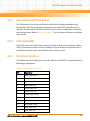
Standard Compliances . . . . . . . . . . . . . . . . . . . . . . . . . . . . . . . . . . . . . . . . . . . . . . . . . . . . . . . . . . . . . . 29
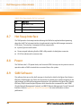
Ordering Information . . . . . . . . . . . . . . . . . . . . . . . . . . . . . . . . . . . . . . . . . . . . . . . . . . . . . . . . . . . . . . . 30
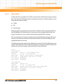
Product Identification . . . . . . . . . . . . . . . . . . . . . . . . . . . . . . . . . . . . . . . . . . . . . . . . . . . . . . . . . . . . . . . 32
Overview . . . . . . . . . . . . . . . . . . . . . . . . . . . . . . . . . . . . . . . . . . . . . . . . . . . . . . . . . . . . . . . . . . . . . . . . . . 35
Site Planning Considerations . . . . . . . . . . . . . . . . . . . . . . . . . . . . . . . . . . . . . . . . . . . . . . . . . . . . . . . . . 35
2.2.1 Receiving and Unpacking the System . . . . . . . . . . . . . . . . . . . . . . . . . . . . . . . . . . . . . . . . . . . 35
2.2.2 Site and Installation Planning . . . . . . . . . . . . . . . . . . . . . . . . . . . . . . . . . . . . . . . . . . . . . . . . . . 36
Requirements . . . . . . . . . . . . . . . . . . . . . . . . . . . . . . . . . . . . . . . . . . . . . . . . . . . . . . . . . . . . . . . . . . . . . . 37
2.3.1 Environmental Requirements. . . . . . . . . . . . . . . . . . . . . . . . . . . . . . . . . . . . . . . . . . . . . . . . . . 37
2.3.2 Power Requirements . . . . . . . . . . . . . . . . . . . . . . . . . . . . . . . . . . . . . . . . . . . . . . . . . . . . . . . . . 39
Dimensions and Weight . . . . . . . . . . . . . . . . . . . . . . . . . . . . . . . . . . . . . . . . . . . . . . . . . . . . . . . . . . . . . 40
Mounting Options . . . . . . . . . . . . . . . . . . . . . . . . . . . . . . . . . . . . . . . . . . . . . . . . . . . . . . . . . . . . . . . . . . 41
Cooling Considerations . . . . . . . . . . . . . . . . . . . . . . . . . . . . . . . . . . . . . . . . . . . . . . . . . . . . . . . . . . . . . 42
Acoustic Noise Control . . . . . . . . . . . . . . . . . . . . . . . . . . . . . . . . . . . . . . . . . . . . . . . . . . . . . . . . . . . . . . 44
System Installation . . . . . . . . . . . . . . . . . . . . . . . . . . . . . . . . . . . . . . . . . . . . . . . . . . . . . . . . . . . . . . . . . . . 45
3.1
3.2
Overview . . . . . . . . . . . . . . . . . . . . . . . . . . . . . . . . . . . . . . . . . . . . . . . . . . . . . . . . . . . . . . . . . . . . . . . . . . 45
Before Installation . . . . . . . . . . . . . . . . . . . . . . . . . . . . . . . . . . . . . . . . . . . . . . . . . . . . . . . . . . . . . . . . . . 45
3.2.1 Requirements . . . . . . . . . . . . . . . . . . . . . . . . . . . . . . . . . . . . . . . . . . . . . . . . . . . . . . . . . . . . . . . 45
AXP 1410 Installation and Use (6806800H70D)
3
Contents
Contents
3.3
3.4
3.5
4
FRU Installation . . . . . . . . . . . . . . . . . . . . . . . . . . . . . . . . . . . . . . . . . . . . . . . . . . . . . . . . . . . . . . . . . . . . . . 61
4.1
4.2
4.3
4.4
4.5
5
Installing and Removing Node Blades and RTMs . . . . . . . . . . . . . . . . . . . . . . . . . . . . . . . . . . . . . . . . 61
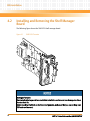
Installing and Removing the Shelf Manager Board . . . . . . . . . . . . . . . . . . . . . . . . . . . . . . . . . . . . . . 62
4.2.1 Installing the Board. . . . . . . . . . . . . . . . . . . . . . . . . . . . . . . . . . . . . . . . . . . . . . . . . . . . . . . . . . . 63
4.2.2 Removing the Board. . . . . . . . . . . . . . . . . . . . . . . . . . . . . . . . . . . . . . . . . . . . . . . . . . . . . . . . . . 64
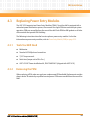
Replacing Power Entry Modules . . . . . . . . . . . . . . . . . . . . . . . . . . . . . . . . . . . . . . . . . . . . . . . . . . . . . . 65
4.3.1 Tools You Will Need . . . . . . . . . . . . . . . . . . . . . . . . . . . . . . . . . . . . . . . . . . . . . . . . . . . . . . . . . . 65
4.3.2 Removing the PEM . . . . . . . . . . . . . . . . . . . . . . . . . . . . . . . . . . . . . . . . . . . . . . . . . . . . . . . . . . . 65
4.3.3 Installing the PEM . . . . . . . . . . . . . . . . . . . . . . . . . . . . . . . . . . . . . . . . . . . . . . . . . . . . . . . . . . . . 68
Installing Fan Tray Modules . . . . . . . . . . . . . . . . . . . . . . . . . . . . . . . . . . . . . . . . . . . . . . . . . . . . . . . . . . 72
4.4.1 Removing the Upper FTM . . . . . . . . . . . . . . . . . . . . . . . . . . . . . . . . . . . . . . . . . . . . . . . . . . . . . 73
4.4.2 Installing the Upper FTM . . . . . . . . . . . . . . . . . . . . . . . . . . . . . . . . . . . . . . . . . . . . . . . . . . . . . . 74
4.4.3 Removing the Lower FTM . . . . . . . . . . . . . . . . . . . . . . . . . . . . . . . . . . . . . . . . . . . . . . . . . . . . . 74
4.4.4 Installing the Lower FTM . . . . . . . . . . . . . . . . . . . . . . . . . . . . . . . . . . . . . . . . . . . . . . . . . . . . . . 75
Installing a Fan Filter . . . . . . . . . . . . . . . . . . . . . . . . . . . . . . . . . . . . . . . . . . . . . . . . . . . . . . . . . . . . . . . . 75
Configuring and Operating the System . . . . . . . . . . . . . . . . . . . . . . . . . . . . . . . . . . . . . . . . . . . . . . . . . 79
5.1
5.2
4
3.2.2 Tools You will Need . . . . . . . . . . . . . . . . . . . . . . . . . . . . . . . . . . . . . . . . . . . . . . . . . . . . . . . . . . 46
Installation . . . . . . . . . . . . . . . . . . . . . . . . . . . . . . . . . . . . . . . . . . . . . . . . . . . . . . . . . . . . . . . . . . . . . . . . 46
3.3.1 Installing the System in a Rack . . . . . . . . . . . . . . . . . . . . . . . . . . . . . . . . . . . . . . . . . . . . . . . . . 48
3.3.2 Connecting the Cables. . . . . . . . . . . . . . . . . . . . . . . . . . . . . . . . . . . . . . . . . . . . . . . . . . . . . . . . 51
3.3.2.1 DC Power Cable . . . . . . . . . . . . . . . . . . . . . . . . . . . . . . . . . . . . . . . . . . . . . . . . . . . . 52
3.3.2.2 Power Cable Termination . . . . . . . . . . . . . . . . . . . . . . . . . . . . . . . . . . . . . . . . . . . . 54
3.3.2.3 Connecting the Cables to the PEM . . . . . . . . . . . . . . . . . . . . . . . . . . . . . . . . . . . . 54
3.3.3 Grounding the System . . . . . . . . . . . . . . . . . . . . . . . . . . . . . . . . . . . . . . . . . . . . . . . . . . . . . . . . 56
3.3.4 Powering Up the System . . . . . . . . . . . . . . . . . . . . . . . . . . . . . . . . . . . . . . . . . . . . . . . . . . . . . . 57
Powering Down the System . . . . . . . . . . . . . . . . . . . . . . . . . . . . . . . . . . . . . . . . . . . . . . . . . . . . . . . . . . 58
Emergency Power Off . . . . . . . . . . . . . . . . . . . . . . . . . . . . . . . . . . . . . . . . . . . . . . . . . . . . . . . . . . . . . . . 58
Overview . . . . . . . . . . . . . . . . . . . . . . . . . . . . . . . . . . . . . . . . . . . . . . . . . . . . . . . . . . . . . . . . . . . . . . . . . . 79
Network Management . . . . . . . . . . . . . . . . . . . . . . . . . . . . . . . . . . . . . . . . . . . . . . . . . . . . . . . . . . . . . . 79
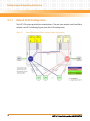
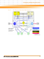
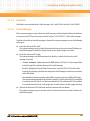
5.2.1 Default VLAN Configuration . . . . . . . . . . . . . . . . . . . . . . . . . . . . . . . . . . . . . . . . . . . . . . . . . . . 80
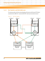
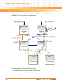
5.2.2 Slot Numbers and Slot Addresses . . . . . . . . . . . . . . . . . . . . . . . . . . . . . . . . . . . . . . . . . . . . . . 82
5.2.3 Shelf Geographical Address . . . . . . . . . . . . . . . . . . . . . . . . . . . . . . . . . . . . . . . . . . . . . . . . . . . 84
AXP 1410 Installation and Use (6806800H70D)
Contents
5.3
5.4
5.5
5.6
5.7
5.8
5.2.3.1 Setting the Shelf Geographical Address . . . . . . . . . . . . . . . . . . . . . . . . . . . . . . . . 84
5.2.3.2 Shelf Manager Replacement Scenarios . . . . . . . . . . . . . . . . . . . . . . . . . . . . . . . . 85
5.2.4 IP Addresses . . . . . . . . . . . . . . . . . . . . . . . . . . . . . . . . . . . . . . . . . . . . . . . . . . . . . . . . . . . . . . . . . 86
5.2.4.1 Out-of-Band Interface . . . . . . . . . . . . . . . . . . . . . . . . . . . . . . . . . . . . . . . . . . . . . . . 88
5.2.4.2 Backplane Interfaces . . . . . . . . . . . . . . . . . . . . . . . . . . . . . . . . . . . . . . . . . . . . . . . . 91
5.2.4.3 Configuration File . . . . . . . . . . . . . . . . . . . . . . . . . . . . . . . . . . . . . . . . . . . . . . . . . . . 94
5.2.5 Restoring Factory Settings . . . . . . . . . . . . . . . . . . . . . . . . . . . . . . . . . . . . . . . . . . . . . . . . . . . . 98
Accessing System Components . . . . . . . . . . . . . . . . . . . . . . . . . . . . . . . . . . . . . . . . . . . . . . . . . . . . . . 99
Software . . . . . . . . . . . . . . . . . . . . . . . . . . . . . . . . . . . . . . . . . . . . . . . . . . . . . . . . . . . . . . . . . . . . . . . . . 100
5.4.1 Installation . . . . . . . . . . . . . . . . . . . . . . . . . . . . . . . . . . . . . . . . . . . . . . . . . . . . . . . . . . . . . . . . . 100
5.4.2 Upgrade . . . . . . . . . . . . . . . . . . . . . . . . . . . . . . . . . . . . . . . . . . . . . . . . . . . . . . . . . . . . . . . . . . . 101
Power Entry Module (PEM) . . . . . . . . . . . . . . . . . . . . . . . . . . . . . . . . . . . . . . . . . . . . . . . . . . . . . . . . . . 102
5.5.1 Description. . . . . . . . . . . . . . . . . . . . . . . . . . . . . . . . . . . . . . . . . . . . . . . . . . . . . . . . . . . . . . . . . 102
5.5.2 IPMC Circuitry . . . . . . . . . . . . . . . . . . . . . . . . . . . . . . . . . . . . . . . . . . . . . . . . . . . . . . . . . . . . . . 103
Fan Tray Modules . . . . . . . . . . . . . . . . . . . . . . . . . . . . . . . . . . . . . . . . . . . . . . . . . . . . . . . . . . . . . . . . . . 104
5.6.1 Description. . . . . . . . . . . . . . . . . . . . . . . . . . . . . . . . . . . . . . . . . . . . . . . . . . . . . . . . . . . . . . . . . 104
5.6.2 Cooling Budget . . . . . . . . . . . . . . . . . . . . . . . . . . . . . . . . . . . . . . . . . . . . . . . . . . . . . . . . . . . . . 105
5.6.3 IPMC Circuitry . . . . . . . . . . . . . . . . . . . . . . . . . . . . . . . . . . . . . . . . . . . . . . . . . . . . . . . . . . . . . . 106
Redundancy . . . . . . . . . . . . . . . . . . . . . . . . . . . . . . . . . . . . . . . . . . . . . . . . . . . . . . . . . . . . . . . . . . . . . . 106
5.7.1 Cold Standby . . . . . . . . . . . . . . . . . . . . . . . . . . . . . . . . . . . . . . . . . . . . . . . . . . . . . . . . . . . . . . . 106
5.7.1.1 Heartbeat . . . . . . . . . . . . . . . . . . . . . . . . . . . . . . . . . . . . . . . . . . . . . . . . . . . . . . . . . 107
5.7.1.2 Data Replication . . . . . . . . . . . . . . . . . . . . . . . . . . . . . . . . . . . . . . . . . . . . . . . . . . . 107
5.7.1.3 HPI Interface . . . . . . . . . . . . . . . . . . . . . . . . . . . . . . . . . . . . . . . . . . . . . . . . . . . . . . 107
5.7.2 System Start-Up Behavior and Dependencies . . . . . . . . . . . . . . . . . . . . . . . . . . . . . . . . . . . 108
5.7.2.1 Shelf Manager . . . . . . . . . . . . . . . . . . . . . . . . . . . . . . . . . . . . . . . . . . . . . . . . . . . . . 108
5.7.2.2 Hub Blade . . . . . . . . . . . . . . . . . . . . . . . . . . . . . . . . . . . . . . . . . . . . . . . . . . . . . . . . . 109
5.7.2.3 System Manager . . . . . . . . . . . . . . . . . . . . . . . . . . . . . . . . . . . . . . . . . . . . . . . . . . . 109
5.7.3 Redundancy Operations . . . . . . . . . . . . . . . . . . . . . . . . . . . . . . . . . . . . . . . . . . . . . . . . . . . . . 111
5.7.3.1 Shelf Manager Switchover . . . . . . . . . . . . . . . . . . . . . . . . . . . . . . . . . . . . . . . . . . 111
5.7.3.2 Shelf Manager Takeover . . . . . . . . . . . . . . . . . . . . . . . . . . . . . . . . . . . . . . . . . . . . 113
5.7.3.3 Shelf Manager Failover . . . . . . . . . . . . . . . . . . . . . . . . . . . . . . . . . . . . . . . . . . . . . 113
5.7.3.4 Shelf Manager Insertion . . . . . . . . . . . . . . . . . . . . . . . . . . . . . . . . . . . . . . . . . . . . 115
5.7.3.5 Shelf Manager Extraction . . . . . . . . . . . . . . . . . . . . . . . . . . . . . . . . . . . . . . . . . . . 116
Blade Insertion and Extraction . . . . . . . . . . . . . . . . . . . . . . . . . . . . . . . . . . . . . . . . . . . . . . . . . . . . . . . 116
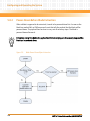
5.8.1 Power-On After Blade Insertion . . . . . . . . . . . . . . . . . . . . . . . . . . . . . . . . . . . . . . . . . . . . . . . 117
5.8.2 Power-Down Before Blade Extraction . . . . . . . . . . . . . . . . . . . . . . . . . . . . . . . . . . . . . . . . . . 118
AXP 1410 Installation and Use (6806800H70D)
5
Contents
Contents
6
Supported IPMI Commands. . . . . . . . . . . . . . . . . . . . . . . . . . . . . . . . . . . . . . . . . . . . . . . . . . . . . . . . . . . 119
6.1
6.2
6.3
7
FRU Information and Sensor Data Records . . . . . . . . . . . . . . . . . . . . . . . . . . . . . . . . . . . . . . . . . . . . . 123
7.1
7.2
7.3
6
Introduction . . . . . . . . . . . . . . . . . . . . . . . . . . . . . . . . . . . . . . . . . . . . . . . . . . . . . . . . . . . . . . . . . . . . . . 119
Standard IPMI Commands . . . . . . . . . . . . . . . . . . . . . . . . . . . . . . . . . . . . . . . . . . . . . . . . . . . . . . . . . . 119
6.2.1 Global IPMI Commands . . . . . . . . . . . . . . . . . . . . . . . . . . . . . . . . . . . . . . . . . . . . . . . . . . . . . . 119
6.2.2 Event Commands . . . . . . . . . . . . . . . . . . . . . . . . . . . . . . . . . . . . . . . . . . . . . . . . . . . . . . . . . . . 119
6.2.3 Sensor Device Commands. . . . . . . . . . . . . . . . . . . . . . . . . . . . . . . . . . . . . . . . . . . . . . . . . . . . 120
6.2.4 FRU Device Commands . . . . . . . . . . . . . . . . . . . . . . . . . . . . . . . . . . . . . . . . . . . . . . . . . . . . . . 120
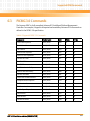
PICMG 3.0 Commands . . . . . . . . . . . . . . . . . . . . . . . . . . . . . . . . . . . . . . . . . . . . . . . . . . . . . . . . . . . . . 121
Introduction . . . . . . . . . . . . . . . . . . . . . . . . . . . . . . . . . . . . . . . . . . . . . . . . . . . . . . . . . . . . . . . . . . . . . . 123
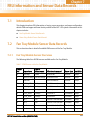
Fan Tray Module Sensor Data Records . . . . . . . . . . . . . . . . . . . . . . . . . . . . . . . . . . . . . . . . . . . . . . . . 123
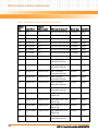
7.2.1 Fan Tray Module Sensor Overview . . . . . . . . . . . . . . . . . . . . . . . . . . . . . . . . . . . . . . . . . . . . . 123
7.2.2 Fan Tray Module Analog Sensors . . . . . . . . . . . . . . . . . . . . . . . . . . . . . . . . . . . . . . . . . . . . . . 125
7.2.2.1 Voltage Sensors . . . . . . . . . . . . . . . . . . . . . . . . . . . . . . . . . . . . . . . . . . . . . . . . . . . 125
7.2.2.2 Temperature Sensors . . . . . . . . . . . . . . . . . . . . . . . . . . . . . . . . . . . . . . . . . . . . . . . 129
7.2.2.3 Fan Speed Sensors . . . . . . . . . . . . . . . . . . . . . . . . . . . . . . . . . . . . . . . . . . . . . . . . . 133
7.2.3 Fan Tray Module Discrete Sensors . . . . . . . . . . . . . . . . . . . . . . . . . . . . . . . . . . . . . . . . . . . . . 142
7.2.3.1 Hot Swap Sensor . . . . . . . . . . . . . . . . . . . . . . . . . . . . . . . . . . . . . . . . . . . . . . . . . . . 143
7.2.3.2 IPMB Link Sensor . . . . . . . . . . . . . . . . . . . . . . . . . . . . . . . . . . . . . . . . . . . . . . . . . . . 143
7.2.3.3 Reserved Sensor . . . . . . . . . . . . . . . . . . . . . . . . . . . . . . . . . . . . . . . . . . . . . . . . . . . 144
7.2.3.4 OEM-Reserved Sensors . . . . . . . . . . . . . . . . . . . . . . . . . . . . . . . . . . . . . . . . . . . . . 145
Power Entry Module Sensor Data Records . . . . . . . . . . . . . . . . . . . . . . . . . . . . . . . . . . . . . . . . . . . . 152
7.3.1 PEM FRU Information . . . . . . . . . . . . . . . . . . . . . . . . . . . . . . . . . . . . . . . . . . . . . . . . . . . . . . . . 152
7.3.2 E-Keying . . . . . . . . . . . . . . . . . . . . . . . . . . . . . . . . . . . . . . . . . . . . . . . . . . . . . . . . . . . . . . . . . . . 153
7.3.3 Power Configuration . . . . . . . . . . . . . . . . . . . . . . . . . . . . . . . . . . . . . . . . . . . . . . . . . . . . . . . . 154
7.3.4 Power Entry Module Sensor Overview . . . . . . . . . . . . . . . . . . . . . . . . . . . . . . . . . . . . . . . . . 154
7.3.5 Power Entry Module Analog Sensors. . . . . . . . . . . . . . . . . . . . . . . . . . . . . . . . . . . . . . . . . . . 155
7.3.5.1 Voltage Sensors . . . . . . . . . . . . . . . . . . . . . . . . . . . . . . . . . . . . . . . . . . . . . . . . . . . 156
7.3.5.2 Current Sensors . . . . . . . . . . . . . . . . . . . . . . . . . . . . . . . . . . . . . . . . . . . . . . . . . . . 161
7.3.5.3 Temperature Sensor . . . . . . . . . . . . . . . . . . . . . . . . . . . . . . . . . . . . . . . . . . . . . . . 162
7.3.6 Power Entry Module Discrete Sensors. . . . . . . . . . . . . . . . . . . . . . . . . . . . . . . . . . . . . . . . . . 163
7.3.6.1 Hot Swap Sensor . . . . . . . . . . . . . . . . . . . . . . . . . . . . . . . . . . . . . . . . . . . . . . . . . . . 163
7.3.6.2 IPMB Link Sensor . . . . . . . . . . . . . . . . . . . . . . . . . . . . . . . . . . . . . . . . . . . . . . . . . . . 164
7.3.6.3 Circuit Breaker State Sensors . . . . . . . . . . . . . . . . . . . . . . . . . . . . . . . . . . . . . . . . 165
AXP 1410 Installation and Use (6806800H70D)
Contents
8
Shelf Management Alarm Module . . . . . . . . . . . . . . . . . . . . . . . . . . . . . . . . . . . . . . . . . . . . . . . . . . . . . 171
8.1
8.2
8.3
8.4
8.5
8.6
8.7
8.8
8.9
A
Overview . . . . . . . . . . . . . . . . . . . . . . . . . . . . . . . . . . . . . . . . . . . . . . . . . . . . . . . . . . . . . . . . . . . . . . . . . 171
Features . . . . . . . . . . . . . . . . . . . . . . . . . . . . . . . . . . . . . . . . . . . . . . . . . . . . . . . . . . . . . . . . . . . . . . . . . . 172
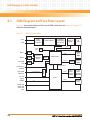
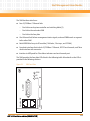
SAM Diagram and Face Plate Layout . . . . . . . . . . . . . . . . . . . . . . . . . . . . . . . . . . . . . . . . . . . . . . . . . 174
Functional Description . . . . . . . . . . . . . . . . . . . . . . . . . . . . . . . . . . . . . . . . . . . . . . . . . . . . . . . . . . . . . 176
8.4.1 IPMB Connectivity. . . . . . . . . . . . . . . . . . . . . . . . . . . . . . . . . . . . . . . . . . . . . . . . . . . . . . . . . . . 176
8.4.2 RS-232 Serial Interface . . . . . . . . . . . . . . . . . . . . . . . . . . . . . . . . . . . . . . . . . . . . . . . . . . . . . . . 176
8.4.3 Master-Only I2C Bus . . . . . . . . . . . . . . . . . . . . . . . . . . . . . . . . . . . . . . . . . . . . . . . . . . . . . . . . . 177
8.4.4 Shelf FRU SEEPROM . . . . . . . . . . . . . . . . . . . . . . . . . . . . . . . . . . . . . . . . . . . . . . . . . . . . . . . . . 177
8.4.5 SAM LEDs . . . . . . . . . . . . . . . . . . . . . . . . . . . . . . . . . . . . . . . . . . . . . . . . . . . . . . . . . . . . . . . . . . 178
8.4.5.1 Hot Swap LED . . . . . . . . . . . . . . . . . . . . . . . . . . . . . . . . . . . . . . . . . . . . . . . . . . . . . 178
8.4.5.2 SAM/ADP Status LEDs . . . . . . . . . . . . . . . . . . . . . . . . . . . . . . . . . . . . . . . . . . . . . . 179
Management and Control . . . . . . . . . . . . . . . . . . . . . . . . . . . . . . . . . . . . . . . . . . . . . . . . . . . . . . . . . . 179
8.5.1 Hardware Monitoring and Control. . . . . . . . . . . . . . . . . . . . . . . . . . . . . . . . . . . . . . . . . . . . . 179
8.5.1.1 Voltage Sensors . . . . . . . . . . . . . . . . . . . . . . . . . . . . . . . . . . . . . . . . . . . . . . . . . . . 180
8.5.1.2 Temperature Monitoring . . . . . . . . . . . . . . . . . . . . . . . . . . . . . . . . . . . . . . . . . . . 180
8.5.1.3 Fan Speed and Control . . . . . . . . . . . . . . . . . . . . . . . . . . . . . . . . . . . . . . . . . . . . . 180
8.5.2 Redundancy Control. . . . . . . . . . . . . . . . . . . . . . . . . . . . . . . . . . . . . . . . . . . . . . . . . . . . . . . . . 183
8.5.2.1 Hardware Redundancy Interface . . . . . . . . . . . . . . . . . . . . . . . . . . . . . . . . . . . . . 183
8.5.2.2 HRI Protocol . . . . . . . . . . . . . . . . . . . . . . . . . . . . . . . . . . . . . . . . . . . . . . . . . . . . . . . 184
8.5.2.3 Ethernet Signals . . . . . . . . . . . . . . . . . . . . . . . . . . . . . . . . . . . . . . . . . . . . . . . . . . . 185
8.5.3 Switchover Signals . . . . . . . . . . . . . . . . . . . . . . . . . . . . . . . . . . . . . . . . . . . . . . . . . . . . . . . . . . 186
Telco Alarm Functionality . . . . . . . . . . . . . . . . . . . . . . . . . . . . . . . . . . . . . . . . . . . . . . . . . . . . . . . . . . . 186
8.6.1 Telco Alarm Cutoff Push Button . . . . . . . . . . . . . . . . . . . . . . . . . . . . . . . . . . . . . . . . . . . . . . . 187
8.6.2 Telco Alarm LEDs. . . . . . . . . . . . . . . . . . . . . . . . . . . . . . . . . . . . . . . . . . . . . . . . . . . . . . . . . . . . 187
8.6.3 Telco Alarm Interface . . . . . . . . . . . . . . . . . . . . . . . . . . . . . . . . . . . . . . . . . . . . . . . . . . . . . . . . 187
Hot Swap Interface . . . . . . . . . . . . . . . . . . . . . . . . . . . . . . . . . . . . . . . . . . . . . . . . . . . . . . . . . . . . . . . . 188
Power . . . . . . . . . . . . . . . . . . . . . . . . . . . . . . . . . . . . . . . . . . . . . . . . . . . . . . . . . . . . . . . . . . . . . . . . . . . . 188
SAM Software . . . . . . . . . . . . . . . . . . . . . . . . . . . . . . . . . . . . . . . . . . . . . . . . . . . . . . . . . . . . . . . . . . . . . 188
8.9.1 imls Utility . . . . . . . . . . . . . . . . . . . . . . . . . . . . . . . . . . . . . . . . . . . . . . . . . . . . . . . . . . . . . . . . . 189
Related Documentation . . . . . . . . . . . . . . . . . . . . . . . . . . . . . . . . . . . . . . . . . . . . . . . . . . . . . . . . . . . . . . 191
A.1
A.2
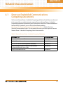
Emerson Embedded Communications Computing Documents . . . . . . . . . . . . . . . . . . . . . . . . . 191
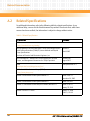
Related Specifications . . . . . . . . . . . . . . . . . . . . . . . . . . . . . . . . . . . . . . . . . . . . . . . . . . . . . . . . . . . . . . 192
AXP 1410 Installation and Use (6806800H70D)
7
Contents
Contents
Safety Notes . . . . . . . . . . . . . . . . . . . . . . . . . . . . . . . . . . . . . . . . . . . . . . . . . . . . . . . . . . . . . . . . . . . . . . . . . . . . 193
Sicherheitshinweise . . . . . . . . . . . . . . . . . . . . . . . . . . . . . . . . . . . . . . . . . . . . . . . . . . . . . . . . . . . . . . . . . . . . . 205
Index . . . . . . . . . . . . . . . . . . . . . . . . . . . . . . . . . . . . . . . . . . . . . . . . . . . . . . . . . . . . . . . . . . . . . . . . . . . . . . . . . . 217
8
AXP 1410 Installation and Use (6806800H70D)
List of Tables
Table 1-1
Table 1-2
Table 2-1
Table 2-2
Table 2-3
Table 5-1
Table 5-2
Table 5-3
Table 5-4
Table 5-5
Table 5-6
Table 6-1
Table 6-2
Table 6-3
Table 6-4
Table 6-5
Table 7-1
Table 7-2
Table 7-3
Table 7-4
Table 7-5
Table 7-6
Table 7-7
Table 7-8
Table 7-9
Table 7-10
Table 7-11
Table 7-12
Table 7-13
Table 7-14
Table 7-15
Table 7-16
Table 7-17
Table 7-18
Table 7-19
Table 7-20
Standard Compliances . . . . . . . . . . . . . . . . . . . . . . . . . . . . . . . . . . . . . . . . . . . . . . . . . . . . . . . 29
Order Numbers . . . . . . . . . . . . . . . . . . . . . . . . . . . . . . . . . . . . . . . . . . . . . . . . . . . . . . . . . . . . . 31
Environmental Conditions . . . . . . . . . . . . . . . . . . . . . . . . . . . . . . . . . . . . . . . . . . . . . . . . . . . . 37
System Power Requirements . . . . . . . . . . . . . . . . . . . . . . . . . . . . . . . . . . . . . . . . . . . . . . . . . 39
Dimensions and Weight of System and Components . . . . . . . . . . . . . . . . . . . . . . . . . . . . 40
Slot Numbering and Slot Addresses . . . . . . . . . . . . . . . . . . . . . . . . . . . . . . . . . . . . . . . . . . . 83
Software Available on System Components . . . . . . . . . . . . . . . . . . . . . . . . . . . . . . . . . . . 100
Available Software Upgrade Tools . . . . . . . . . . . . . . . . . . . . . . . . . . . . . . . . . . . . . . . . . . . . 101
PEM IPMB Addresses . . . . . . . . . . . . . . . . . . . . . . . . . . . . . . . . . . . . . . . . . . . . . . . . . . . . . . . 104
Cooling Budget . . . . . . . . . . . . . . . . . . . . . . . . . . . . . . . . . . . . . . . . . . . . . . . . . . . . . . . . . . . . 105
Start up Dependencies of the Shelf Manager and the Hub Blade . . . . . . . . . . . . . . . . . . 108
Supported Global IPMI Commands . . . . . . . . . . . . . . . . . . . . . . . . . . . . . . . . . . . . . . . . . . . 119
Supported Event Commands . . . . . . . . . . . . . . . . . . . . . . . . . . . . . . . . . . . . . . . . . . . . . . . . 119
Supported Sensor Device Commands . . . . . . . . . . . . . . . . . . . . . . . . . . . . . . . . . . . . . . . . 120
Supported FRU Commands . . . . . . . . . . . . . . . . . . . . . . . . . . . . . . . . . . . . . . . . . . . . . . . . . 120
Supported PICMG 3.0 Commands . . . . . . . . . . . . . . . . . . . . . . . . . . . . . . . . . . . . . . . . . . . . 121
IPMI Sensors on the Fan Tray Module . . . . . . . . . . . . . . . . . . . . . . . . . . . . . . . . . . . . . . . . . 123
Sensor No. 3 +12V A_MON . . . . . . . . . . . . . . . . . . . . . . . . . . . . . . . . . . . . . . . . . . . . . . . . . . 125
Sensor No. 4 +12V B_MON . . . . . . . . . . . . . . . . . . . . . . . . . . . . . . . . . . . . . . . . . . . . . . . . . . 126
Sensor No. 5 +3.3V . . . . . . . . . . . . . . . . . . . . . . . . . . . . . . . . . . . . . . . . . . . . . . . . . . . . . . . . . 127
Sensor No. 6 +5V A_MON . . . . . . . . . . . . . . . . . . . . . . . . . . . . . . . . . . . . . . . . . . . . . . . . . . . 128
Sensor No. 7 +5V B_MON . . . . . . . . . . . . . . . . . . . . . . . . . . . . . . . . . . . . . . . . . . . . . . . . . . . 128
Sensor No. 30 FTM Temp 1 . . . . . . . . . . . . . . . . . . . . . . . . . . . . . . . . . . . . . . . . . . . . . . . . . . 129
Sensor No. 31 FTM Temp 2 . . . . . . . . . . . . . . . . . . . . . . . . . . . . . . . . . . . . . . . . . . . . . . . . . . 130
Sensor No. 32 FTM Temp 3 . . . . . . . . . . . . . . . . . . . . . . . . . . . . . . . . . . . . . . . . . . . . . . . . . . 131
Sensor No. 33 FTM Temp 4 . . . . . . . . . . . . . . . . . . . . . . . . . . . . . . . . . . . . . . . . . . . . . . . . . . 131
Sensor No. 34 FTM Temp 5 . . . . . . . . . . . . . . . . . . . . . . . . . . . . . . . . . . . . . . . . . . . . . . . . . . 132
Sensor No. 35 FTM Temp 6 . . . . . . . . . . . . . . . . . . . . . . . . . . . . . . . . . . . . . . . . . . . . . . . . . . 133
Sensor No. 8 Fan 1 . . . . . . . . . . . . . . . . . . . . . . . . . . . . . . . . . . . . . . . . . . . . . . . . . . . . . . . . . . 133
Sensor No. 9 Fan 2 . . . . . . . . . . . . . . . . . . . . . . . . . . . . . . . . . . . . . . . . . . . . . . . . . . . . . . . . . . 134
Sensor No. 10 Fan 3 . . . . . . . . . . . . . . . . . . . . . . . . . . . . . . . . . . . . . . . . . . . . . . . . . . . . . . . . 135
Sensor No. 11 Fan 4 . . . . . . . . . . . . . . . . . . . . . . . . . . . . . . . . . . . . . . . . . . . . . . . . . . . . . . . . 136
Sensor No. 12 Fan 5 . . . . . . . . . . . . . . . . . . . . . . . . . . . . . . . . . . . . . . . . . . . . . . . . . . . . . . . . 136
Sensor No. 13 Fan 6 . . . . . . . . . . . . . . . . . . . . . . . . . . . . . . . . . . . . . . . . . . . . . . . . . . . . . . . . 137
Sensor No. 14 Fan 1 Outlet . . . . . . . . . . . . . . . . . . . . . . . . . . . . . . . . . . . . . . . . . . . . . . . . . . 138
Sensor No. 15 Fan 2 Outlet . . . . . . . . . . . . . . . . . . . . . . . . . . . . . . . . . . . . . . . . . . . . . . . . . . 139
AXP 1410 Installation and Use (6806800H70D)
9
List of Tables
Table 7-21
Table 7-22
Table 7-23
Table 7-24
Table 7-25
Table 7-26
Table 7-27
Table 7-28
Table 7-29
Table 7-30
Table 7-31
Table 7-32
Table 7-33
Table 7-34
Table 7-35
Table 7-36
Table 7-37
Table 7-38
Table 7-39
Table 7-40
Table 7-41
Table 7-42
Table 7-43
Table 7-44
Table 7-45
Table 7-46
Table 7-47
Table 7-48
Table 7-49
Table 7-50
Table 7-51
Table 7-52
Table 7-53
Table 7-54
Table 7-55
Table 8-1
10
Sensor No. 16 Fan 3 Outlet . . . . . . . . . . . . . . . . . . . . . . . . . . . . . . . . . . . . . . . . . . . . . . . . . . 139
Sensor No. 17 Fan 4 Outlet . . . . . . . . . . . . . . . . . . . . . . . . . . . . . . . . . . . . . . . . . . . . . . . . . . 140
Sensor No. 18 Fan 5 Outlet . . . . . . . . . . . . . . . . . . . . . . . . . . . . . . . . . . . . . . . . . . . . . . . . . . 141
Sensor No. 19 Fan 6 Outlet . . . . . . . . . . . . . . . . . . . . . . . . . . . . . . . . . . . . . . . . . . . . . . . . . . 142
Sensor No. 0, Hot Swap . . . . . . . . . . . . . . . . . . . . . . . . . . . . . . . . . . . . . . . . . . . . . . . . . . . . . 143
Sensor No. 2, IPMB Physical . . . . . . . . . . . . . . . . . . . . . . . . . . . . . . . . . . . . . . . . . . . . . . . . . . 143
Sensor No. 1 Version change . . . . . . . . . . . . . . . . . . . . . . . . . . . . . . . . . . . . . . . . . . . . . . . . . 144
Sensor No. 20 FanFault Z1F1 . . . . . . . . . . . . . . . . . . . . . . . . . . . . . . . . . . . . . . . . . . . . . . . . . 145
Sensor No. 21 FanFault Z1F2 . . . . . . . . . . . . . . . . . . . . . . . . . . . . . . . . . . . . . . . . . . . . . . . . . 146
Sensor No. 22 FanFault Z1F3 . . . . . . . . . . . . . . . . . . . . . . . . . . . . . . . . . . . . . . . . . . . . . . . . . 147
Sensor No. 23 FanFault Z2F1 . . . . . . . . . . . . . . . . . . . . . . . . . . . . . . . . . . . . . . . . . . . . . . . . . 147
Sensor No. 24 FanFault Z2F2 . . . . . . . . . . . . . . . . . . . . . . . . . . . . . . . . . . . . . . . . . . . . . . . . . 148
Sensor No. 25 FanFault Z2F3 . . . . . . . . . . . . . . . . . . . . . . . . . . . . . . . . . . . . . . . . . . . . . . . . . 149
Sensor No. 26 FuseFail 48VA1 . . . . . . . . . . . . . . . . . . . . . . . . . . . . . . . . . . . . . . . . . . . . . . . . 149
Sensor No. 27 FuseFail 48VA2 . . . . . . . . . . . . . . . . . . . . . . . . . . . . . . . . . . . . . . . . . . . . . . . . 150
Sensor No. 28 FuseFail 48VB1 . . . . . . . . . . . . . . . . . . . . . . . . . . . . . . . . . . . . . . . . . . . . . . . . 151
Sensor No. 29 FuseFail 48VB2 . . . . . . . . . . . . . . . . . . . . . . . . . . . . . . . . . . . . . . . . . . . . . . . . 151
Power Configuration for PEMs . . . . . . . . . . . . . . . . . . . . . . . . . . . . . . . . . . . . . . . . . . . . . . . 154
IPMI Sensors on the PEM . . . . . . . . . . . . . . . . . . . . . . . . . . . . . . . . . . . . . . . . . . . . . . . . . . . .154
Sensor No. 2 +3.3V . . . . . . . . . . . . . . . . . . . . . . . . . . . . . . . . . . . . . . . . . . . . . . . . . . . . . . . . . 156
Sensor No. 3 +12V Measure . . . . . . . . . . . . . . . . . . . . . . . . . . . . . . . . . . . . . . . . . . . . . . . . . 157
Sensor No. 4 +5V Measure . . . . . . . . . . . . . . . . . . . . . . . . . . . . . . . . . . . . . . . . . . . . . . . . . . . 157
Sensor No. 5 +12V CC . . . . . . . . . . . . . . . . . . . . . . . . . . . . . . . . . . . . . . . . . . . . . . . . . . . . . . . 158
Sensor No. 13, 48.0V FEED_1 . . . . . . . . . . . . . . . . . . . . . . . . . . . . . . . . . . . . . . . . . . . . . . . . 159
Sensor No. 14, 48.0V FEED_2 . . . . . . . . . . . . . . . . . . . . . . . . . . . . . . . . . . . . . . . . . . . . . . . . 160
Sensor No. 15 Current Measure1 . . . . . . . . . . . . . . . . . . . . . . . . . . . . . . . . . . . . . . . . . . . . . 161
Sensor No. 16 Current Measure2 . . . . . . . . . . . . . . . . . . . . . . . . . . . . . . . . . . . . . . . . . . . . . 161
Sensor No. 12 LM73 Temp . . . . . . . . . . . . . . . . . . . . . . . . . . . . . . . . . . . . . . . . . . . . . . . . . . . 162
Sensor No. 0, Hot Swap . . . . . . . . . . . . . . . . . . . . . . . . . . . . . . . . . . . . . . . . . . . . . . . . . . . . . 163
Sensor No. 1, IPMB Physical . . . . . . . . . . . . . . . . . . . . . . . . . . . . . . . . . . . . . . . . . . . . . . . . . . 164
Sensor No. 5, CB 1 . . . . . . . . . . . . . . . . . . . . . . . . . . . . . . . . . . . . . . . . . . . . . . . . . . . . . . . . . . 165
Sensor No. 6 CB 2 . . . . . . . . . . . . . . . . . . . . . . . . . . . . . . . . . . . . . . . . . . . . . . . . . . . . . . . . . . 166
Sensor No. 7 CB 3 . . . . . . . . . . . . . . . . . . . . . . . . . . . . . . . . . . . . . . . . . . . . . . . . . . . . . . . . . . 167
Sensor No. 8 CB 4 . . . . . . . . . . . . . . . . . . . . . . . . . . . . . . . . . . . . . . . . . . . . . . . . . . . . . . . . . . 167
Sensor No. 9 CB 5 . . . . . . . . . . . . . . . . . . . . . . . . . . . . . . . . . . . . . . . . . . . . . . . . . . . . . . . . . . 168
RJ-45 Serial Port Connector . . . . . . . . . . . . . . . . . . . . . . . . . . . . . . . . . . . . . . . . . . . . . . . . . . 176
AXP 1410 Installation and Use (6806800H70D)
List of Tables
Table 8-2
Table 8-3
Table 8-4
Table 8-5
Table 8-6
Table 8-7
Table 8-8
Table A-1
Table A-2
Alarm Display Panel (ADP) Serial Port Connector . . . . . . . . . . . . . . . . . . . . . . . . . . . . . . . 177
SAM LEDs . . . . . . . . . . . . . . . . . . . . . . . . . . . . . . . . . . . . . . . . . . . . . . . . . . . . . . . . . . . . . . . . . 178
Hot Swap LED States . . . . . . . . . . . . . . . . . . . . . . . . . . . . . . . . . . . . . . . . . . . . . . . . . . . . . . . 178
SAM LED Status Indicators . . . . . . . . . . . . . . . . . . . . . . . . . . . . . . . . . . . . . . . . . . . . . . . . . . 179
ADP LED Status Indicators . . . . . . . . . . . . . . . . . . . . . . . . . . . . . . . . . . . . . . . . . . . . . . . . . . . 179
Cooling Budget . . . . . . . . . . . . . . . . . . . . . . . . . . . . . . . . . . . . . . . . . . . . . . . . . . . . . . . . . . . . 182
Hot Swap Interface Pin Out . . . . . . . . . . . . . . . . . . . . . . . . . . . . . . . . . . . . . . . . . . . . . . . . . . 187
Emerson Network Power - Embedded Computing Publications . . . . . . . . . . . . . . . . . . 191
Related Specifications . . . . . . . . . . . . . . . . . . . . . . . . . . . . . . . . . . . . . . . . . . . . . . . . . . . . . . 192
AXP 1410 Installation and Use (6806800H70D)
11
List of Tables
12
AXP 1410 Installation and Use (6806800H70D)
List of Figures
Figure 1-1
Figure 1-2
Figure 1-3
Figure 1-4
Figure 1-5
Figure 1-6
Figure 1-7
Figure 2-1
Figure 2-2
Figure 3-1
Figure 3-2
Figure 3-3
Figure 4-1
Figure 4-2
Figure 4-3
Figure 4-4
Figure 5-1
Figure 5-2
Figure 5-3
Figure 5-4
Figure 5-5
Figure 5-6
Figure 5-7
Figure 5-8
Figure 5-9
Figure 8-1
Figure 8-2
Figure 8-3
Figure 8-4
System Front View . . . . . . . . . . . . . . . . . . . . . . . . . . . . . . . . . . . . . . . . . . . . . . . . . . . . . . 24
System Rear View . . . . . . . . . . . . . . . . . . . . . . . . . . . . . . . . . . . . . . . . . . . . . . . . . . . . . . . 25
Slot Distribution . . . . . . . . . . . . . . . . . . . . . . . . . . . . . . . . . . . . . . . . . . . . . . . . . . . . . . . . 27
System Label Location . . . . . . . . . . . . . . . . . . . . . . . . . . . . . . . . . . . . . . . . . . . . . . . . . . . 32
System Label Example . . . . . . . . . . . . . . . . . . . . . . . . . . . . . . . . . . . . . . . . . . . . . . . . . . . 33
Serial Number Location . . . . . . . . . . . . . . . . . . . . . . . . . . . . . . . . . . . . . . . . . . . . . . . . . . 34
Serial Number Label Example . . . . . . . . . . . . . . . . . . . . . . . . . . . . . . . . . . . . . . . . . . . . . 34
Rack Mounting Dimensions . . . . . . . . . . . . . . . . . . . . . . . . . . . . . . . . . . . . . . . . . . . . . . 42
Shelf Airflow . . . . . . . . . . . . . . . . . . . . . . . . . . . . . . . . . . . . . . . . . . . . . . . . . . . . . . . . . . . . 43
Rack Mounting Dimensions . . . . . . . . . . . . . . . . . . . . . . . . . . . . . . . . . . . . . . . . . . . . . . 50
DC Power Connection Detail . . . . . . . . . . . . . . . . . . . . . . . . . . . . . . . . . . . . . . . . . . . . . . 53
Grounding Lugs . . . . . . . . . . . . . . . . . . . . . . . . . . . . . . . . . . . . . . . . . . . . . . . . . . . . . . . . . 56
SAM1410 Overview . . . . . . . . . . . . . . . . . . . . . . . . . . . . . . . . . . . . . . . . . . . . . . . . . . . . . 62
Upper Rear FTM Ejector Handles and LEDs . . . . . . . . . . . . . . . . . . . . . . . . . . . . . . . . . . 73
Lower Front FTM Ejector Handles and LEDs . . . . . . . . . . . . . . . . . . . . . . . . . . . . . . . . . 74
Position of the Fan Filter . . . . . . . . . . . . . . . . . . . . . . . . . . . . . . . . . . . . . . . . . . . . . . . . . . 77
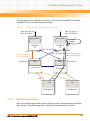
Switch Management Fabric Interface Bridge Configuration . . . . . . . . . . . . . . . . . . . 80
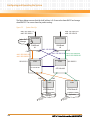
Switch Management Base Interface Bridge Configuration . . . . . . . . . . . . . . . . . . . . 81
Dual Star Topology . . . . . . . . . . . . . . . . . . . . . . . . . . . . . . . . . . . . . . . . . . . . . . . . . . . . . . 82
IP Addresses . . . . . . . . . . . . . . . . . . . . . . . . . . . . . . . . . . . . . . . . . . . . . . . . . . . . . . . . . . . . 87
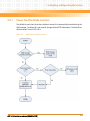
System Start-Up . . . . . . . . . . . . . . . . . . . . . . . . . . . . . . . . . . . . . . . . . . . . . . . . . . . . . . . 110
Shelf Manager Switchover . . . . . . . . . . . . . . . . . . . . . . . . . . . . . . . . . . . . . . . . . . . . . . . 112
Link Failover after Active Shelf Manager Failover . . . . . . . . . . . . . . . . . . . . . . . . . . . . 115
Blade Power-On After Insertion . . . . . . . . . . . . . . . . . . . . . . . . . . . . . . . . . . . . . . . . . . 117
Blade Power-Down Before Extraction . . . . . . . . . . . . . . . . . . . . . . . . . . . . . . . . . . . . . 118
Block Diagram of SAM . . . . . . . . . . . . . . . . . . . . . . . . . . . . . . . . . . . . . . . . . . . . . . . . . . 174
SAM Face Plate . . . . . . . . . . . . . . . . . . . . . . . . . . . . . . . . . . . . . . . . . . . . . . . . . . . . . . . . . 175
SAM HRI Interconnection . . . . . . . . . . . . . . . . . . . . . . . . . . . . . . . . . . . . . . . . . . . . . . . 184
Interhub Slot and Shelf Manager Connectivity . . . . . . . . . . . . . . . . . . . . . . . . . . . . . 185
AXP 1410 Installation and Use (6806800H70D)
13
List of Figures
14
AXP 1410 Installation and Use (6806800H70D)
About this Manual
Overview of Contents
This manual is divided into the following chapters and appendix.
z
Chapter 1, System Overview, on page 23, provides a brief introduction to the AXP 1410.
z
Chapter 2, Site Preparation, on page 35, provides general information such as unpacking
the system, requirements, dimensions and weight.
z
Chapter 3, System Installation, on page 45 describes how to install, power up and power
down the system.
z
Chapter 4, FRU Installation, on page 61 describes how to install field replaceable units, such
as boards, power entry modules or fans.
z
Chapter 5, Configuring and Operating the System, on page 79 gives information on network
management, software, accessing system components, and power and cooling
subsystems.
z
Chapter 6, Supported IPMI Commands, on page 119 lists standard, PICMG, and Emersonspecific IPMI commands.
z
Chapter 7, FRU Information and Sensor Data Records, on page 123 lists FRU information and
SDRs of PEMs and FTMs.
z
Chapter 8, Shelf Management Alarm Module, on page 171 describes the shelf management
alarm module.
z
Appendix A, Related Documentation, on page 191 lists relevant documentation and
specifications.
z
Safety Notes on page 193 lists all safety notes relevant for this system.
z
Sicherheitshinweise on page 205 is a German translation of the safety notes chapter.
AXP 1410 Installation and Use (6806800H70D)
15
About this Manual
About this Manual
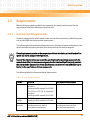
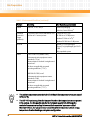
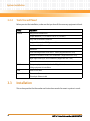
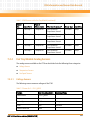
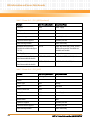
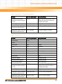
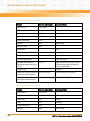
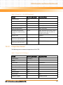
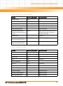
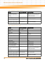
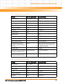
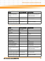
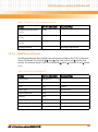
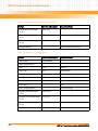
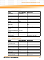
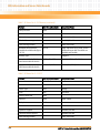
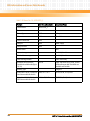
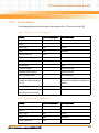
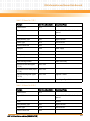
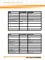
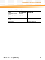
Abbreviations
This document uses the following abbreviations:
16
Abbreviation
Definition
ACO
Alarm Cut-Off
ADP
Alarm Display Panel
AMC
Alarm Management Controller
ANSI
American National Standards Institute
ARP
Address Resolution Protocol
AWG
American Wire Gauge
BBS
Basic Blade Services
CISPR
Comité Internationale Spécial des Perturbations
Radioelectrotechnique
CLI
Command Line Interface
CO
Central Office
CSA
Canadian Standards Association
DHCP
Dynamic Host Configuration Protocol
ECC
Error Correcting Code
EMC
Electromagnetic Compatibility
EMI
Electromagnetic Interference
EMV
Elektromagnetische Verträglichkeit
ESD
Electrostatic Discharge
ETS
European Telecom Standard
ETSI
European Telecommunication Standards Institute
FAE
Field Application Engineer
FCC
Federal Communications Commission
FCU
Firmware Upgrade Utility
FPGA
Field Programmable Gate Array
FRU
Field Replaceable Unit
AXP 1410 Installation and Use (6806800H70D)
About this Manual
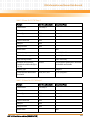
Abbreviation
Definition
FTM
Fan Tray Module
FUMI
Firmware Update Management Instrument
GA
General Availability
GPIO
General Purpose Input/Output
GND
Ground
HPI
Hardware Platform Interface
HRI
Hardware Redundancy Interface
2
I C
Inter-integrated Circuit
I/O
Input/Output
ID
Identifier
IEC
International Electrotechnical Commission
IEEE
Institute of Electrical and Electronics Engineers
IP
Internet Protocol
IPM
Intelligent Platform Management
IPMB
Intelligent Platform Management Bus
IPMC
Intelligent Platform Management Controller
IPMI
Intelligent Platform Management Interface
IS
In Service
LED
Light Emitting Diode
LUN
Logical Units
NEBS
Network Equipment Building System
NetFn
Network function (code)
OEM
Original Equipment Manufacturer
OOS
Out Of Service
PCI
Peripheral Component Interconnect (bus)
PE
Primary Earth
PEM
Power Entry Module
PICMG
PCI Industrial Computer Manufacturers Group
AXP 1410 Installation and Use (6806800H70D)
17
About this Manual
About this Manual
18
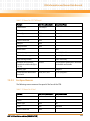
Abbreviation
Definition
PN
Part Number
RFI
Radio Frequency Interference
RFS
Root File System
RMCP
Remote Management Control Protocol
ROM
Read Only Memory
RTM
Rear Transition Module
RoHS
Directive on the restriction of the use of certain hazardous substances
in electrical and electronic equipment
S/N
Serial Number
SA
Shelf Address
SAM
Shelf Management Alarm Module
SDR
Sensor Data Record
SELV
Safety Extra Low Voltage
SGA
Shelf Geographical Address
ShMC
Shelf Management Controller
ShMM
Shelf Management Mezzanine Module
SNMP
Simple Network Management Protocol
SOC
System On a Chip
SSH
Secure Shell
TBD
To Be Defined
TDM
Time-Division Multiplexing
TNV
Telephone Network Voltage
TPE
Twisted-Pair Ethernet
UL
Underwriters Laboratory
VCCI
Voluntary Control Council for Interference
VDC
DC Voltage
VLAN
Virtual Local Area Network
AXP 1410 Installation and Use (6806800H70D)
About this Manual
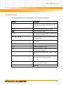
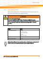
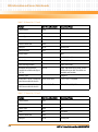
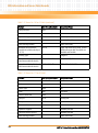
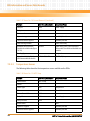
Conventions
The following table describes the conventions used throughout this manual.
Notation
Description
0x00000000
Typical notation for hexadecimal numbers (digits are
0 through F), for example used for addresses and
offsets
0b0000
Same for binary numbers (digits are 0 and 1)
bold
Used to emphasize a word
Screen
Used for on-screen output and code related elements
or commands in body text
Courier + Bold
Used to characterize user input and to separate it
from system output
Reference
Used for references and for table and figure
descriptions
File > Exit
Notation for selecting a submenu
<text>
Notation for variables and keys
[text]
Notation for software buttons to click on the screen
and parameter description
...
Repeated item for example node 1, node 2, ..., node
12
.
Omission of information from example/command
that is not necessary at the time being
.
.
..
Ranges, for example: 0..4 means one of the integers
0,1,2,3, and 4 (used in registers)
|
Logical OR
AXP 1410 Installation and Use (6806800H70D)
19
About this Manual
About this Manual
Notation
Description
Indicates a hazardous situation which, if not avoided,
could result in death or serious injury
Indicates a hazardous situation which, if not avoided,
may result in minor or moderate injury
Indicates a property damage message
No danger encountered. Pay attention to important
information
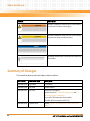
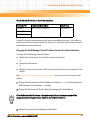
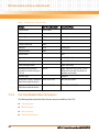
Summary of Changes
This manual has been revised and replaces all prior editions.
Part Number
Publication Date
Description
6806800H70A
April 2009
First edition
6806800H70B
July 2009
Second edition
6806800H70C
July 2010
Removed F120 support
Updated sections 5.2, Network Management and 5.3,
Accessing System Components
Corrected FTM Temperature Sensor tables
Centellis 4410 is renamed to AXP 1410
6806800H70D
20
October 2010
Added Chapter 8, Shelf Management Alarm Module, on
page 171.
AXP 1410 Installation and Use (6806800H70D)
About this Manual
Comments and Suggestions
We welcome and appreciate your comments on our documentation. We want to know what
you think about our manuals and how we can make them better.
Mail comments to us by filling out the following online form:
http://www.emersonnetworkpowerembeddedcomputing.com/ > Contact Us > Online Form
In "Area of Interest" select "Technical Documentation". Be sure to include the title, part number,
and revision of the manual and tell us how you used it.
AXP 1410 Installation and Use (6806800H70D)
21
About this Manual
About this Manual
22
AXP 1410 Installation and Use (6806800H70D)
Chapter 1
System Overview
1.1
Description
The AXP 1410 system is a high availability AdvancedTCA (Advanced Telecom Computing
Architecture) system. The PICMG 3.X AdvancedTCA Specifications define components for highperformance services solutions. It is an architecture for highly-available and scalable highspeed interconnect technologies.
A high-availability system consists of software and redundant hardware to ensure five-nines
(99,999%) uptime. This means that a system is unavailable for no more than 5.26 minutes per
year.
Your system is equipped with the following components
z
Dual star backplane with base and fabric interface providing connector interfaces for
power distribution, input/output connectivity between front blades and mechanical
alignment and support
z
Subrack providing attachment points for backplane, alignment, support and mechanical
engagement for insertion and extraction of front blades and RTMs
z
Two Emerson SAM1410 shelf manager boards with integrated alarm boards
Each AdvancedTCA blade and Field Replaceable Unit (FRU) provides connections to the
shelf manager through an Intelligent Platform Management Bus (IPMB).
z
12 node slots which can be equipped with AdvancedTCA blades
z
Two hub slots which can be equipped with AdvancedTCA hub blades
z
14 slots at the system's rear side which can be populated with 14 RTMs
These RTM connections provide user-defined input and output connectivity to the
corresponding front blades.
z
Two DC hot swappable 2N+1 redundant Power Entry Modules (PEM)
z
Fan Tray Modules (FTM)
z
Alarm Display Panel (ADP) for telco alarms located on the front of the chassis
AXP 1410 Installation and Use (6806800H70D)
23
System Overview
z
Air filter
z
ESD wrist strap sockets and grounding studs
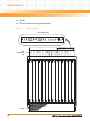
Figure 1-1
System Front View
Alarm Display Panel
ACT A
COM A
COM B
ACT B
PWR MIN MAJ CRT
ACO
ACT A
COM A
COM B
ACT B
PWR MIN MAJ CRT
ACO
Cable
Management
Tray
FanTray
24
AXP 1410 Installation and Use (6806800H70D)
System Overview
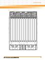
Figure 1-2
System Rear View
AXP 1410 Installation and Use (6806800H70D)
25
System Overview
1.1.1
Shelf
The AXP 1410 shelf consists of a formed 13U sheet metal card cage with structure and support
for the backplane, PEMs, FTMs, SAMs, and 14 card slots. Figure 1-1 on page 24 provides a front
view of the shelf, Figure 1-2 on page 25 provides a rear view of the shelf.
The enclosure mounts in a 19" rack or optional EIA 23" rack. Mounting holes for bezel brackets
are provided, which allows the use of power supply or card cage (customer designed) bezels.
1.1.2
Backplane
The backplane is fully compliant with the PICMG 3.0 R2.0 Specification and it has been designed
with the following features:
1.1.3
z
Two hub slots
z
12 node slots
z
14-slot fabric interface with dual star interconnect
z
Base interface with dual star interconnect
z
Base interface to the shelf manager slots
z
Update interface between physical adjacent slots
z
Bused IPMB-0 connections
z
Synchronization clock buses
Shelf Manager
The shelf manager SAM1410 is designed to be used in AdvancedTCA systems. It is the central
management unit of the shelf. Its purpose is to monitor, control and assure proper operation
of the shelf and all other components of the AdvancedTCA shelf.
It reports anomalies and errors and takes corrective actions if required (for example, increase
the speed of the fans). The SAM1410 has access to detailed inventory information as well as
sensor status information of the shelf and all components of the shelf.
The SAM1410 is fully compliant to the shelf management functions as specified in the PICMG
3.0 R2.0 Specification.
26
AXP 1410 Installation and Use (6806800H70D)
System Overview
For a detailed description refer to the SAM1410 Installation and Use and the System Management
Interface Based on HPI-B (Centellis CO 31kX/4100/2000/4410).
1.1.4
Blades
The backplane in a AXP 1410 system provides 12 node slots. They are located to the left and to
the right of the two hub slots in the middle.
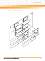
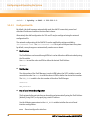
Figure 1-3
Slot Distribution
Power
Segm ents
FTM - 1
A3 B3
1
13
2
11
3
9
4
7
5
5
A1
B1
A1
B1
A1
B1
A1
B1
A1
B1
7
3
8
4
9
2
A1
B1
A1
B1
A2
B2
A2
B2
10
6
11
8
12
10
13
12
14
14
A2
B2
A2
B2
A2
B2
A2
B2
A2
B2
HUB - B
ATCA
Blade
Slots
Power
Segm ents
6
1
HUB - A
Physical
Logical
FTM - 2
Lower FTM
A4
B4
A A
1 3
C1
A
2
B
1
A
4
Lower Rear
SAM - A
PEM - A
A1
B1
A2
B2
PEM A-48V/ RTN
PEM B-48V/ RTN
PEM A- 48V/ RTN
PEM B- 48V/ RTN
SAM - B
C1
D1
C1
A3
B3
A4
B4
PEM
PEM
PEM
PEM
A- 48V/ RTN
B- 48V/ RTN
A- 48V/ RTN
B- 48V/ RTN
B
3
D1
B
2
B
4
PEM - B
D1
C1
D1
PEM A 12V/ RTN
PEM B 12V/ RTN
The node slots can be equipped with AdvancedTCA blades. Emerson provides several highperformance, single slot, hot-swappable node blades.
AXP 1410 Installation and Use (6806800H70D)
27
System Overview
1.1.5
Hub Slots
The hub slots are configured as option 9 dual star PICMG 3.0 base interface and PICMG 3.1
10Gb fabric interface.
1.1.6
Rear Transition Modules
The AdvancedTCA blades can be connected to Rear Transition Modules (RTM) to provide easy
access to I/O signals through the zone 3 connector defined by the AdvancedTCA specification.
The Emerson RTMs can be used as rear expansion boards for node blades and for the switch to
access the different interfaces on an AdvancedTCA blade through the RTM face plate.
1.1.7
Power Entry Modules
The Power Entry Module (PEM) is a Field Replaceable Unit (FRU) and can be replaced while the
system is on, but the power for the PEM being replaced (PEM A or PEM B) must be shut down
at the external source. Replacement can take place in under 30 minutes by a trained service
person.
The PEMs are accessible from the rear of the shelf and connect to the PEM connectors on the
backplane. A removable plastic housing covers the power feeds and returns to prevent
accidental shorting. The PEM also features an injector/ejector handle that provides the hot
swap mechanism for signalling the state of the PEM prior to removal.
The PEMs are hot-swappable and will not cause a fault when one is removed for replacement.
Two PEMs are required to support 2N+1 redundancy. If your system is configured for
redundant operation using two power feeds, they operate in load sharing where the total load
is equal to or less than what one power feed can provide.
1.1.8
Fan Tray Modules
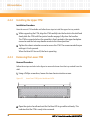
The AXP 1410 supports two fan trays in a push/pull configuration. Each fan tray contains five
dual counter rotating fans. The lower fan tray is accessible from the front of the chassis and
contains the replaceable air filter. The upper fan tray is located in the rear of the chassis.
28
AXP 1410 Installation and Use (6806800H70D)
System Overview
1.1.9
Fan Filter
The fan filter is installed in the lower fan tray.
1.2
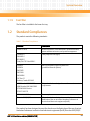
Standard Compliances
The product meets the following standards:
Table 1-1 Standard Compliances
Standard
Description
PICMG3.0 R2.0,
Defines mechanics, board dimensions, power distribution,
power and data connectors, and system management.
UL 60950-1
Safety Requirements (legal)
EN 60950-1
IEC 60950-1
CAN/CSA C22.2 No 60950-1
CISPR 22
CISPR 24
EMC requirements (legal) on system level
(predefined Emerson system)
EN 55022
EN 55024
EN 300386
FCC Part 15
Industry Canada ICES-003
NEBS Standard GR-63-CORE
NEBS Standard GR-1089-CORE
The product has been designed to meet these environmental
requirements.
ETSI EN 300 019 series
ETSI ETS 300 753
ETSI EN 300 132-2
Power requirements
Directive 2002/95/EC
The product has been designed to meet the directive on the
Restriction of the use of certain Hazardous Substances in
electrical and electronic equipment (RoHS).
The product has been designed to meet the directive on the Restriction of the use of certain
Hazardous Substances in electrical and electronic equipment (RoHS) Directive 2002/95/EC.
AXP 1410 Installation and Use (6806800H70D)
29
System Overview
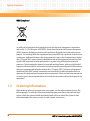
WEEE Compliance
4363 0205
To satisfy the requirements for marking electrical and electronic equipment in accordance
with article 11 (2) of Directive 2002/96/EC, Waste from Electrical and Electronic Equipment
(WEEE), Emerson includes a crossed-out bin symbol on all standard and noncustom chassis
product. This marking fulfills the requirement set out by WEEE that a producer of an electrical
or electronic appliance that bears their trade name and is put on the European Union market
after 13 August 2005, places a clearly identifiable mark on the equipment and that this mark
signifies that equipment is to be reprocessed or recycled using authorized recyclers and
processes. This minimizes the disposal of unsorted municipal waste, achieves a high level of
separate collection of WEEE, and ensures the environmentally sound disposal of electrical and
electronic equipment placed on the market after 13 August 2005. To dispose of equipment
marked with the WEEE symbol, Emerson has contracted with certified companies that can
reprocess this equipment per European Union requirements. Please visit the Emerson web site
or contact your Emerson representative to find out who to contact and how to dispose of the
equipment.
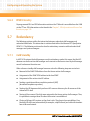
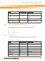
1.3
Ordering Information
When ordering variants or spare parts for your system, use the order numbers given on the
following pages. To make sure that you are ordering spare parts that can be used with your
system, check the system identification label placed at the rear side of the system to find
information about the system variant, its order number and revision.
30
AXP 1410 Installation and Use (6806800H70D)
System Overview
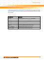
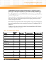
As of the printing date of this manual, the AXP 1410 Installation and Use supports the system
models listed below. Consult your local sales representative for ordering information on spare
parts not listed.
Table 1-2 Order Numbers
Order Number
Description
AXP1410
AdvancedTCA shelf - 14 slot, 19", 13U - 10G backplane
UFT-1440
Upper fan tray module for AXP1440 shelf
LFT-1440
Lower fan tray module for AXP1440 shelf
SAM1410
Shelf manager for AXP1410 shelf
PEM1620
Power entry module for AXP1620 and AXP1440
AXP-F-FILL-PANEL-F
Blank filler panel, AXP1620 & AXP1440 - front
AXP-R-FILL-PANEL-F
Blank filler panel, AXP1620 & AXP1440 - rear
AXP 1410 Installation and Use (6806800H70D)
31
System Overview
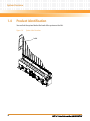
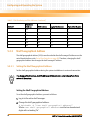
1.4
Product Identification
You can find the system label at the back of the system on the left.
Figure 1-4
System Label Location
Label
32
AXP 1410 Installation and Use (6806800H70D)
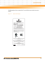
System Overview
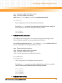
The following figure shows a sample label. The actual label on your product may vary in
content.
Figure 1-5
System Label Example
TYPE: Centellis 4410 Platform Core
MODEL: 44XX-C
VOLTAGE: - 40 to - 60 VDC (SELV)
- 60 to - 72 VDC (TNV-2)
CURRENT: 2 X 50A (Total 100A)
MAX 3500 WATTS
This device complies with Part 15 of the FCC Rules.
Operation is subject to the following two rules:
(1) This device may not cause harmful interference, and
(2) This device must accept any interference received,
including interference that may cause undesired operation.
This Class A digital apparatus complies with Canadian
ICES-003.
Cet appariel numerique de la classe A est conforne a la
norme NMB-003 du Canada.
WARNING
Multiple power sources are present. Service only by qualified
service person. Refer to the Installation Guide.
AVERTISSEMENT
Des sources multiples de pouvoir sont présentes. L'entretien e
cet équipement doit être effectué par du personnel de service
qualifié. Veuillez vous référer au guide d’instalation.
WARNUNG
Es gibt mehrere Spannungsquellen Wartung ausschließlich
durch qualifiziertes Wartungspersonal Siehe auch
Installtionsanleitung
3306844B02A
AXP 1410 Installation and Use (6806800H70D)
33
System Overview
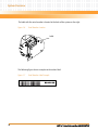
The label with the serial number is located at the back of the system on the right.
Figure 1-6
Serial Number Location
Label
The following figure shows a sample serial number label.
Figure 1-7
34
Serial Number Label Example
AXP 1410 Installation and Use (6806800H70D)
Chapter 2
Site Preparation
2.1
Overview
The following sections help you to prepare system installation:
2.2
Section
Gives Information On
Site Planning Considerations
This section includes information on unpacking and
inspecting the system, requirements, technical data, and
other information you need to know before you start
system installation.
Site Planning Checklists
This section provides checklists for site preparation.
Site Planning Considerations
This section provides information to prepare the site and the shelf for installation.
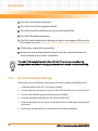
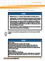
2.2.1
Receiving and Unpacking the System
Damage of Circuits
Electrostatic discharge and incorrect module installation and removal can damage circuits
or shorten their life.
Before touching the module or electronic components, make sure that you are working in
an ESD-safe environment.
Shipment Inspection
To inspect the shipment perform the following steps:
1. Verify that you have received all items of your shipment.
Compare the shipment thoroughly with the delivery note.
2. Visually inspect the shelf to ensure that all of the connector pins are straight,
shrouds are properly seated, screws are tight, etc..
AXP 1410 Installation and Use (6806800H70D)
35
Site Preparation
3. Check the rails for proper alignment.
4. Check that the air filter is properly installed.
5. Check that the cable connections are secure and properly fitted.
6. Check the EMI gaskets for damage.
7. Check the items listed above for damage and report any damage or differences to
the customer service at www.emersonnetworkpower.com/embeddedcomputing.
8. Tighten loose screws before proceeding.
9. Remove the desiccant bags delivered together with the system and dispose of
them according to your country’s legislation.
The product is thoroughly inspected before shipment. If any damage occurred during
transportation or any items are missing, please contact our customer's service immediately.
2.2.2
Site and Installation Planning
Planning basic site and installation requirements you have to consider the following issues:
1. Is adequate power for the AXP 1410 system available?
2. Can the system be positioned in a way that -48 to -60V DC power source is easy to reach?
3. Are racks with sufficient space to install the system available?
4. Is suitable equipment available to lift the system into the rack?
5. Is there enough space to run a system console terminal? Is the cable long enough to reach
the system?
6. Are the inlet and outlet of the fans and therefore the airflow not blocked?
36
AXP 1410 Installation and Use (6806800H70D)
Site Preparation
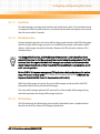
2.3
Requirements
Before and during system installation and operation, you always have to ensure that the
requirements listed in the following sections are met.
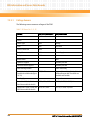
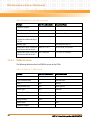
2.3.1
Environmental Requirements
To ensure proper function of the system, make sure that the environment in which the system
is to be used fulfills the environmental requirements.
The environmental values must be tested and proven in the planned system configuration, that
means the delivered system and other third-party products you want to integrate.
Operating temperatures refer to the temperature of the air circulating at the air intake of the
system and not to component temperatures.
Some of the climatic values may exceed the specification of some system components (for
example hard disks). As Emerson cannot guarantee the functionality of third party products
that are handled or operated out of their specifications, the environmental conditions may be
limited to the specifications of these components.
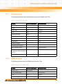
The following table lists the environmental requirements.
Table 2-1 Environmental Conditions
Feature
Operating
Non-Operating (packed state)
Temperature
+5ºC (41°F) to +40ºC (104°F) (normal
operation)
according to NEBS standard GR-63-CORE
-40°C (-40°F) to +70°C (158°F)
-5°C (23°F) to +55°C (131°F) (exceptional
operation)
according to NEBS standard GR-63-CORE
Temp.
change
+/-0.25°C/min
according to NEBS standard GR-63-CORE
+/-0.25°C/min
Relative
humidity
5% to 90% non-condensing
according to Emerson-internal
environmental requirements
5% to 95% non-condensing
according to Emerson-internal
environmental requirements
AXP 1410 Installation and Use (6806800H70D)
37
Site Preparation
Table 2-1 Environmental Conditions (continued)
Feature
Shock
Operating
Half-sine, 11 ms, 30 m/s
Non-Operating (packed state)
2
Blade level packaging
Half-sine, 6 ms at 180 m/s2
Vibration
(tested in
target
platform)
0.1g from 5 Hz to 100 Hz and back to 5 Hz
at a rate of 0.1 octave/minute
Free fall
-
5-20 Hz at 0.01 g2/Hz
20-200 Hz at -3.0 dB/octave
Random 5-20 Hz at 1m2/s3
Random 20-200 Hz at -3 dB/octave
300mm (11.8 in) (packaged)
25mm (1 in) (unpackaged) per GR-63CORE
fully populated system
Noise
-
ETSI ETS 300 753 (October 1997)
Telecommunication equipment rooms
(attended): 7.2 bel
Measurement of "declared A-weight sound
power level"
All values are applicable to normal
operating conditions (~23°C).
NEBS GR-63-CORE, Issue 3
Telecommunication equipment rooms
(attended): 78 dB
Measurement of "declared A-weight sound
power level"
All values are applicable to normal
operating conditions (~27°C).
38
z
The ambient temperature around the shelf and the air inlet temperature must not exceed
55°C (131°F).
z
The AXP 1410 system regulates the fan speed based on the temperature sensors present
in the system. The fan speed is adjusted to the lowest speed which still keeps the
evaluated temperature readings below or at their respective "upper non-critical
threshold". Hence, the fan speed depends on the ambient temperature, blade design,
temperature threshold settings, and system configuration.
AXP 1410 Installation and Use (6806800H70D)
Site Preparation
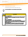
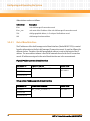
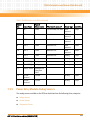
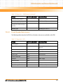
2.3.2
Power Requirements
Make sure that a suitable -40.0 to -72 VDC power source is within reach of the system. Two
power entry modules (PEMs) can be installed in the system.
Personal Injury or System Damage
The system is supplied by a TNV-2 voltage. This voltage is considered hazardous.
Make sure that the external power supply meets the relevant safety standards. Ensure that
TNV-2 is separated from dangerous voltages (mains) through double or reinforced
insulation.
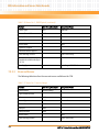
Table 2-2 System Power Requirements
Feature
Value
Voltage and input current
Voltage:
-40 to 60 VDC (SELV)
-60 to -72 VDC (TNV-2)
Current:
80 X 2 (160 A Total)
Chassis idle power
170 W
Chassis maximum power
870 W
When installing additional blades or modules, make sure that the power consumption of all
installed modules does not exceed the system's maximum power dissipation.
AXP 1410 Installation and Use (6806800H70D)
39
Site Preparation
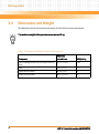
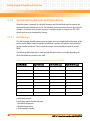
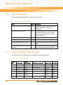
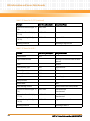
2.4
Dimensions and Weight
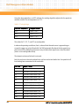
The table below lists the dimensions and weight of the shelf and system components.
The maximum weight of the system must not exceed 80 kg.
Table 2-3 Dimensions and Weight of System and Components
Dimensions
40
Component
w x h x d in mm
Weight in kg
Shelf, including two fan trays, two PEMs, and an air
filter
497 x 573 x 544
39.6
PEM
164 x 73 x 155
1.5
Upper fan tray module
491 x 87 x 227
4
Lower fan tray module
491 x 119 x 331
6.1
AXP 1410 Installation and Use (6806800H70D)
Site Preparation
2.5
Mounting Options
You can simply operate the system on your desk or you can install it in a EIA 23" rack, or mount
it in a 600mmx600mm ETSI frame relay..
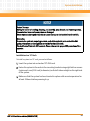
Personal Injury or System Damage
The system is heavy and if you carry it on your own you can hurt your back.
To prevent injury, keep your back straight and have two people lift the system or use
additional lifting equipment.
Personal or System Damage
Unstable system installation in a rack can cause the rack to topple over.
Therefore, if your system is the only one in the rack, make sure to mount the system in the
lowest part of the rack. If other systems are installed in one rack, start with the heaviest
component at the bottom.
If the rack is equipped with stabilizing devices, make sure that they are installed and
extended so that the rack is secure. Then proceed to mount or service the system.
During the course of handling, shipping, and assembly, pins, shrouds and mounting screws,
fans and other items can become loose or damaged.
Do not operate a damaged shelf, this can cause damage to devices that interfere with it.
Grounding
To ensure the system is properly grounded, each of the system's parts contact the EMI
gasket. The system contains gaskets at the shelf and module level.
The shelf is also fitted with ESD contacts. Please take care for proper ESD protection of the
operator.
AXP 1410 Installation and Use (6806800H70D)
41
Site Preparation
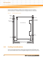
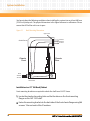
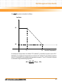
You have to keep the following conditions when installing the system into a 600 mm
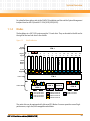
(23.62 inch) deep rack. The physical dimensions in the figure below are in millimeters.
Figure 2-1
Rack Mounting Dimensions
Cabinet
Door
Air Outlet
3.5mm
to Door
at Back Side
of Rear Door
25mm Thick
Door, 2X
13U Shelf Side View
3mm
to Door
Air Inlet
75mm
42mm
550mm Inside, Door to Door
600mm Deep Cabinet
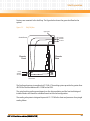
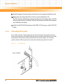
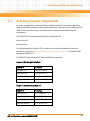
2.6
Cooling Considerations
The AXP 1410 provides fault tolerant cooling to front-mounted AdvancedTCA blades and to
rear transition modules based on two hot swappable intelligent fan trays with five fans per tray.
42
AXP 1410 Installation and Use (6806800H70D)
Site Preparation
Fan trays are mounted in the shelf top. The figure below shows the general airflow for the
system.
Figure 2-2
Shelf Airflow
Upper FTM
Chassis
Exhaust
Air Flow
Outlet Plenum
RTM
Chassis
Front
Chassis
Rear
Room
Ambient
Air Flow
PEM
Exhaust
Lower Front Air Intake
Lower FTMs
The Cooling subsystem is compliant to CP-TA B.4. The cooling system provides for greater than
40 CFM for the front blade and 5.0 CFM for the RTM.
The actual cooling performance depends on the slot population and the heat sink design of
installed blades and should be validated based on the used configuration.
The cooling subsystem is designed to provide 31.1 CFM in the front and presence of any single
cooling failure.
AXP 1410 Installation and Use (6806800H70D)
43
Site Preparation
2.7
Acoustic Noise Control
The system can generate a lot of acoustic noise. This system has a built-in noise control due to
the fan speed control. If the system is installed in an environment where the noise may be
harmful to personnel being exposed to the noise during extended time periods, additional
protective measures should be considered.
44
AXP 1410 Installation and Use (6806800H70D)
Chapter 3
System Installation
3.1
Overview
The following sections help you to start up and maintain the system:
3.2
Step
Description
Before installation
This section provides information about the requirements, unpacking and
inspecting the delivery and the type label location.
Installation
This section provides information about how to mount the system into a rack
and how to ground the system.
Removal
This section provides information on how to power down the system and
remove it from a rack.
Before Installation
This section provides the following information:
3.2.1
z
Type label location
z
Requirements
z
Tools you will need
Requirements
The power input cables must have a minimum cross section of 21 mm2, AWG 4.
AXP 1410 Installation and Use (6806800H70D)
45
System Installation
3.2.2
Tools You will Need
Before you start the installation, make sure that you have all the necessary equipment at hand.
Usage
Equipment
General
Philipps head screwdriver #1
Torque Wrenches (7, 8, 10 mm or 0.28, 0.31, 0.39 inch)
Large and small socket screwdriver
Large, medium and small Philipps screwdrivers
Nut driver with 7/16 mm socket
Multimeter
Front mounting brackets for an EIA 23’’ frame (shipped with AXP 1410)
AdvancedTCA PEM service Kit, PN 67068008A01 (shipped with AXP 1410)
Right-angle cable lug kit, PN 6706808A01 (shipped with AXP 1410)
Antistatic mat
Shelf
Transport equipment: Hand truck or forklift/pallet truck
Lifting equipment for installation
PEM
Power Feed Cables
System Access
Crossover cable
Twisted pair Ethernet cable
3.3
Installation
This section provides the information and instructions needed to mount a system in a rack.
46
AXP 1410 Installation and Use (6806800H70D)
System Installation
Observe the following general safety notes when installing your system:
z
Restricted access area - The system is only to be installed in a restricted access area.
z
Installation codes - This unit must be installed in accordance with the National Electrical
Code, Articles 110.16, 110.17, and 110.18 and the Canadian Electrical Code, Section 12.
z
Conductor ampacity - According to UL 60950, Annex NAE (NEC Article 645-5(a)), the
branch-circuit conductors supply must have an ampacity of not less than 125% of the
total connected load. Per NEC Article 310.15 and Table 310.16, the minimum American
Wire Gauge (AWG) has to be selected.
z
Overcurrent protection - A readily accessible listed branch-circuit overcurrent protective
device must be incorporated into the building wiring.
Emerson is not responsible for regulatory compliance or malfunction of any user-modified
product.
System Damage
Environmental contamination can impair system operation.
Locate the system in a stable area free of movement and free of dust, smoke, and
electrostatic discharge (ESD). Make sure, that the temperature does not exceed the
operating temperature given in the environmental requirements in this manual and allow
room for proper air cooling.
System Overheating
Improper cooling leads to blade damage.
To ensure proper cooling always operate the system in a horizontal position. Furthermore,
keep clear at least 6 cm adjacent to the cooling vents on the chassis front and back side.
AXP 1410 Installation and Use (6806800H70D)
47
System Installation
3.3.1
Installing the System in a Rack
The following procedure describes how to install the system in a rack.
Use power input cables with a cross section (minimum) of 21mm2, AWG 4.
Personal or System Damage
The system is heavy and if you carry it on your own you can hurt your back. To prevent injury,
keep your back straight and have two people to lift the system or use additional lifting
equipment.
Personal or System Damage
Unstable system installation in a rack can cause the rack to topple over.
Therefore, if your system is the only one in the rack, make sure to mount the system in the
lowest part of the rack. If other systems are installed in one rack, start with the heaviest
component at the bottom.
If the rack is equipped with stabilizing devices, make sure that they are installed and
extended so that the rack is secure. Then proceed to mount or service the system.
48
AXP 1410 Installation and Use (6806800H70D)
System Installation
System Damage
During the course of handling, shipping, and assembly, pins, shrouds and mounting screws,
fans and other items can become loose or damaged.
Do not operate a damaged shelf, this can cause damage to devices that interfere with it.
Grounding
To ensure the system is properly grounded, each of the system's parts contact the EMI
gasket. The system contains gaskets at the shelf and module level.
The shelf is also fitted with ESD contacts. Please take care for proper ESD protection of the
operator.
Installation in a 19" Rack
To install a system in a 19" rack, proceed as follows:
1. Insert the system into a standard 19" ANSI rack.
2. Fasten the system to the rack via the mounting brackets using eight bolts or screws
(minimum 6 mm (0.24 inch) in diameter) on the left side and eight on the right side
of the system.
3. Make sure that the system has been located in a place with room temperature for
at least 24 hours before powering it up.
AXP 1410 Installation and Use (6806800H70D)
49
System Installation
You have to keep the following conditions when installing the system into an at least 600 mm
(23.62 inch) deep rack. The physical dimensions in the figure below are in millimeters. Please
ensure that 60% of the rack's rear is open.
Figure 3-1
Rack Mounting Dimensions
Upper FTM
Chassis
Exhaust
Air Flow
Outlet Plenum
RTM
Chassis
Front
Chassis
Rear
Room
Ambient
Air Flow
PEM
Exhaust
Lower Front Air Intake
Lower FTMs
Installation in a 23’’ EIA Rack/Cabinet
Front mounting brackets are required to attach the shelf to an EIA 23" frame.
1. Locate the standard mounting hole and slot locations on the front mounting
flanges on the AXP 1410 shelf.
2. Fasten the mounting brackets to the back side of the front chassis flanges using M6
screws x 12mm at each of the 5 locations.
50
AXP 1410 Installation and Use (6806800H70D)
System Installation
3. Be sure to mount the shelf with metal screws or bolts that give a good electrical
connection between the screws or bolts and the mounting surface.
4. Tighten all screws using a torque setting of 35.5 to 38.5 inch-pounds.
Failure to observe proper grounding practices may cause a variety of noise, electrostatic
discharge, and RFI (Radio Frequency Interference) problems.
Installation in a 600 mm ETSI Rack/Cabinet
The shelf mounts directly from the integrated flange on the front of the shelf.
1. Locate the standard mounting hole and slot locations on the front integrated
mounting flanges on the AXP 1410 shelf.
2. Fasten the mounting brackets to the back side of the front chassis flanges using M6
screws x 12mm at each of the 5 locations.
3. Be sure to mount the shelf with metal screws or bolts that give a good electrical
connection between the screws or bolts and the mounting surface.
4. Tighten all screws using a torque setting of 35.5 to 38.5 inch-pounds.
Failure to observe proper grounding practices may cause a variety of noise, electrostatic
discharge, and RFI (Radio Frequency Interference) problems.
3.3.2
Connecting the Cables
AXP 1410 Installation and Use (6806800H70D)
51
System Installation
3.3.2.1
DC Power Cable
Power is introduced to the shelf via redundant DC PEMs. The recommended power cable is an
4 AWG gauge that meets the specifications for this shelf. There are four lugs for each PEM. Two
are straight and the other two are custom offset lugs. The end that connects to the external DC
power source should be equipped with an 8mm terminal.
Always check with your local building authorities for wire sizing requirements for your
environment.
The installation must comply with the 1993 National Electric Code (NEC) and other
applicable codes.
The DC power inputs must only be attached to approved Telephone Network Voltage (TNV)
or SELV (Safety Extra Low Voltage) branch circuits. Branch circuits must comply with all
requirements called for in these safety standards: IEC 60950, EN 60950, CAN/CSA-C22.2 No.
60950. Attaching inputs to non-TNV/SELV approved power sources will cause the system to
fail compliance with safety regulations.
The ground wire must be connected to a reliable earth ground connection to comply with
Class 1 Equipment requirements.
Multiple power sources are present.
Service only by qualified service personnel.
Mehrfache Energiequellen.
Handhabung nur durch geschultes Personal.
Des sources multiples de pouvoir sont présentes.
L'entretien de cet équipement doit être effectué par du personnel de service qualifié.
52
Wire
Signal
Earth Ground
PE GND (Primary Earth Ground)
Input power
-48VDC nominal to -60VDC
Return
-48VDC RETURN
AXP 1410 Installation and Use (6806800H70D)
System Installation
Figure 3-2
DC Power Connection Detail
ON
F
OF
N
C
RT
VD
C
ON
-48
VD
F
OF
N
C
-48
RT
VD
C
-48
VD
AXP 1410 Installation and Use (6806800H70D)
53
System Installation
3.3.2.2
Power Cable Termination
Custom lugs are used with large gauge wires for up to 80 AMPs DC (4 AWG) when connecting
to the PEM. These are shipped with the product.The lugs are angled to allow the cables to be
dressed below the cable management tray, thus protecting the circuit breakers from
accidental tripping.
Terminating this lug is identical to terminating standard lugs. To minimize shorting of the
terminals, the lugs must be insulated according to the following illustration.
Heat shrink should be placed as close to the hole as possible (0.15") apart. The heat shrink
tube should be cut approximately at a 30° angle.
3.3.2.3
Connecting the Cables to the PEM
In a redundant configuration, each PEM must be connected to a separate DC power source.
Power is introduced to each PEM’s terminal block on the front of the module (power input
cable and return cable). The lugs provide secure contact for the cable and prevent the power
cables from rotating. A plastic housing covers the power feeds and returns and is attached with
one screw. Refer to Figure 3-2 for detail.
To cable a dual breaker DC system, read all cautions and warnings, properly ground the
equipment by following the procedure in Grounding the System on page 56, and follow
these steps. This procedure assumes that the PEMs are preinstalled in the shelf.
54
AXP 1410 Installation and Use (6806800H70D)
System Installation
Procedure
Have the following tools on hand before you begin these steps: standard Phillips screwdriver,
nut driver, torque wrench, multimeter, and lug kit.
1. Locate the target power input cable’s terminals at the branch circuit or power
distribution unit. Open the external circuit breakers that provide DC feed power to
the PEM.
2. Lock and tagout the circuit breakers on the branch circuit or power distribution
unit.
Cables may or may not be preinstalled at the branch circuit or power distribution unit.
If the DC power cables are not connected to the branch circuit or power distribution unit,
connect the power cables to the PEMs before connecting the DC power cables to the
external power source.
If the DC power cables are connected to the branch circuit or power distribution unit, a
qualified service person must confirm that the power to the cables is terminated (off) before
continuing the steps to attach the cables to the PEMs.
In either case, use a multimeter to check the PEM end of the terminals to confirm there is no
power present.
3. Using the appropriate tool, carefully remove the plastic covering over the terminal
blocks.
4. Confirm that there is no power to the PEM lug bolts. Using a multimeter, measure
between the two lugs and then measure between the chassis ground and each lug.
If the DC potential is 3.0VDC or less, then power is not present.
5. Attach the DC power cables (input and return) to the dual lug bolts on each PEM.
6. Using a torque wrench, tighten the nuts with a recommended torque setting of
35.5 to 38.5 inch-pounds. Make sure all DC leads are fastened securely.
7. Replace the plastic cover over the terminal blocks.
8. Verify that the circuit breakers are in the ON position.
AXP 1410 Installation and Use (6806800H70D)
55
System Installation
9. Break the tagout or lockout seals on the branch circuit or power distribution unit.
10.Apply power by closing the branch circuit or power distribution unit.
The OOS indicator LED will glow solid red and the other LEDs will go dark. The OOS
will not go dark and the IS indicator LED will not illuminate until the external power
circuit breakers are closed.
11.Verify that all FRU LEDs illuminate and the PEM’s IS LED is green, and the OOS LED
is dark.
3.3.3
Grounding the System
Use a 2 AWG wire with a 2-hole copper lug and connect directly to the earth ground point
located on the right side of the back of the shelf; connect the other end of the wire to a reliable
earth ground. Use the torque setting required by the connector supplier. The 2-hole lug
prevents rotation of the lug and ensures a permanent bonding of ground to the shelf.
Figure 3-3
56
Grounding Lugs
AXP 1410 Installation and Use (6806800H70D)
System Installation
The AXP 1410 shelf was tested in the default configuration of logic ground and shelf ground
connected and does not connect -48VDC Return with Shelf Ground. The system has been
tested in the default configuration and complies with safety and regulatory standards. As a
compliant AdvancedTCA shelf, the AXP 1410 allows system integrator at their own discretion
to remove the mechanism which connects Logic Ground to Shelf Ground and install the
mechanism that connects -48VDC Return to Shelf Ground. If the system integrator exercises
the option of removing the connections from Logic Ground to Shelf Ground or adds the
connection between -48VDC Return and Shelf Ground, the responsibility for maintaining
compliance to CSA (C/US)/VDE safety requirements and EMI/RFI emission limits rests entirely
with the system integrator and installer.
3.3.4
Powering Up the System
With the installation cabled up, you are ready to apply power to the system.
Cover all open module slots and put all approved filler panels in place before turning on
power. This is necessary to properly cool the chassis and to avoid electrical shock and other
possible hazards. Slot covers and panels must remain in place during system operation.
Procedure
Follow these steps to power up the system:
1. Push the PEM circuit breakers to the ON position.
2. Verify that all FRU LEDs illuminate and the PEM’s In Service LED is green.
The system executes its normal start-up routine and is then ready to use.
AXP 1410 Installation and Use (6806800H70D)
57
System Installation
3.4
Powering Down the System
Procedure
Follow these steps to shut down your AXP 1410.
1. Shut down all software operations and the operating system. For shelves with
independently running segments, each segment must be shut down.
2. Turn each circuit breaker on the front of PEM A and PEM B to the OFF position.
Step 2 removes the input power from the slots in the AXP 1410 shelf only. It does not
remove power to the PEMs. To remove power to these components, refer to the next step.
3. Disable the DC power at each of the external sources (branch circuit or power
distribution unit) for both PEM A and PEM B.
4. This completely removes power from the shelf and its subassemblies.
3.5
Emergency Power Off
Procedure
Read this caution and follow the next steps if it is necessary to remove power during an
emergency situation.
Following this procedure will result in a loss of data and may cause damage to chassis
components in a running platform. Use this method only when normal shutdown
procedures cannot be followed.
58
AXP 1410 Installation and Use (6806800H70D)
System Installation
1. Turn each circuit breaker on the front of PEM A and PEM B to the OFF position.
2. Disable the DC power at the external sources (branch circuit or power distribution
unit) for PEM A and PEM B).
AXP 1410 Installation and Use (6806800H70D)
59
System Installation
60
AXP 1410 Installation and Use (6806800H70D)
Chapter 4
FRU Installation
4.1
Installing and Removing Node Blades and RTMs
Refer to the respective blade or RTM documentation for installation and removal procedures.
AXP 1410 Installation and Use (6806800H70D)
61
FRU Installation
4.2
Installing and Removing the Shelf Manager
Board
The following figure shows the SAM1410 shelf manager board.
Figure 4-1
SAM1410 Overview
Damage of Circuits
Electrostatic discharge and incorrect blade installation and removal can damage circuits or
shorten their life.
Before touching the blade or electronic components, make sure that you are working in an
ESD-safe environment.
62
AXP 1410 Installation and Use (6806800H70D)
FRU Installation
If the shelf contains only one shelf manager board you have to power down the shelf before
exchanging the board.
4.2.1
Installing the Board
To install the board into an AdvancedTCA shelf, proceed as follows.
Installation Procedure
The following procedure describes the installation of the board. It assumes that your system is
powered. If your system is unpowered, you can disregard the blue LED and thus skip the
respective step. In this case it is a purely mechanical installation.
1. Put on an ESD wrist strap.
2. Connect the strap to the shelf by attaching the front or rear ESD jack.
3. Set the rotary switches according to your needs.
4. Insert the module into the shelf by placing the top and bottom edges of the board
in the card guides of the shelf. Ensure that the guiding module of shelf and board
are aligned properly. The alignment pin facilitates the insertion and prevents bent
pins.
5. Slide the module into the shelf.
6. Rotate the ejector handle upward until it snaps into place.
7. Wait until the blue LED is illuminated.
8. Screw in the captive screw hand tight.
The blue LED blinks.
9. Wait until the blue LED is switched OFF.
The switched off blue LED indicates that the board is activated.
AXP 1410 Installation and Use (6806800H70D)
63
FRU Installation
4.2.2
Removing the Board
This section describes how to remove the board from an AdvancedTCA system.
Removal Procedure
The following procedure describes how to remove the board from a system. It assumes that
the system is powered. If the system is unpowered, you can disregards the blue LED and thus
skip the respective step. In that case it is a purely mechanical procedure.
1. Put on an ESD wrist strap.
2. Connect the strap to the shelf by attaching the front or rear ESD jack.
3. Unlatch the ejector handle by lifting up the center sliding portion of the handle,
then rotate the handle slightly (about 15 degrees).
The blue LED blinks indicating that the module power down process is ongoing.
4. Wait until the blue LED is illuminated permanently.
Data Loss
Removing the board with the blue LED still blinking causes data loss.
Wait until the blue LED is permanently illuminated, before removing the board.
5. Press the handle down to its fully-open position (about 90 degrees).
The board should start to move out of the chassis. Do not force it. If the SAM does
not move, it means the captive screw is not fully unscrewed. Unscrew until loose
and rotate the ejector handle down.
6. Remove the module from the shelf.
64
AXP 1410 Installation and Use (6806800H70D)
FRU Installation
4.3
Replacing Power Entry Modules
The AXP 1410 supports two Power Entry Modules (PEMs). Since the shelf is equipped with a
redundant power distribution system, the removal of a single PEM does not interrupt system
operation. PEMs are accessible from the rear of the shelf. Each PEM has EMI gaskets on all sides
of the module that provide EMI shielding.
The following instructions describe how to replace a power entry module. For further
information on power entry modules, refer to Power Entry Module (PEM) on page 102.
4.3.1
4.3.2
Tools You Will Need
z
Multimeter
z
Standard #2 Phillips-head screwdriver
z
7/16" Torque wrench
z
Nut driver (torque nut to 50 in. lbs.)
z
AXP 1410 DC Power Installation Kit, PN 6706822A01 (shipped with AXP 1410)
Removing the PEM
When replacing a PEM, make sure you have a replacement PEM available. Replacement can take
place in under 30 minutes by a qualified service person. PEMs are accessible from the rear of the
shelf.
AXP 1410 Installation and Use (6806800H70D)
65
FRU Installation
Replacing one PEM is done while the other PEM is in operation. Having the PEM located in the
shelf is critical to maintaining proper airflow and cooling of the shelf. Steps in which a PEM is
removed from a slot and reinserted should be completed within 3 minutes to maintain the
shelf within safe operating temperatures.
Read all cautions and warnings, and ensure the equipment is properly grounded by
reviewing the procedure in Grounding the System on page 56, and follow these steps. The
PEM has multiple power sources. This procedure should be followed precisely to ensure the
PEM is isolated from all power sources before removing the PEM from the shelf, or removing
the plastic terminal block lug cover.
This procedure assumes that the redundant PEMs are powered on in the shelf.
Removal Procedure
To remove a PEM follow the steps.
1. Locate the target power input cable’s terminals at the branch circuit or power
distribution unit. Open the external circuit breakers that provide DC feed power to
the PEM you are replacing.
OFF
ON
OFF
-48 VDC RTN
-48
ON
-48 VDC RTN
VDC
-48
OOS
IS
VDC
HS
2. Lock and tagout the circuit breakers on the branch circuit or power distribution
unit.
66
AXP 1410 Installation and Use (6806800H70D)
FRU Installation
3. Using the appropriate tool, loosen the chassis retention screws on each side of the
PEM.
4. Open the ejector latches. This will signal the switch to deactivate the hot swap
signal. Watch for the Blue LED to go solid and steady, signalling that it is ready to
remove.
5. Open the ejector handles completely. You will feel the PEM disconnect from the
backplane.
6. Pull the module straight out from the rail guides, about 3 inches.
7. With the PEM in place and before removing the terminal block lug cover, screw a
standoff/lockout screw extension onto the retaining screws located on each side of
the PEM. Align the threaded end of the standoff/lockout screw extension with the
screw holes on each side of the shelf and securely tighten to lock the PEM
approximately 2 inches out of the shelf.
8. Using the appropriate tool, carefully remove the terminal block cover (plastic
covering) over the terminal block. The terminal block cover is attached to the
terminal block by two tabs with slots in the cover that insert into embossments in
the terminal block wall. To remove the cover, press the upper wall of the terminal
block wall downward and slip a flat-bladed screwdriver between the cover and the
terminal block wall and pry the cover tab up to relieve it from the embossment in
the terminal block wall. Once the upper cover tab is free from the terminal block
embossment, the cover should rotate downward and free itself from the lower
embossment.
If the multimeter indicates there is still power present and power cannot be removed from
the terminals, the entire shelf must be powered down to perform the PEM replacement.
9. Confirm that there is no power to the PEM lug bolts. Using a multimeter, measure
between the two lugs and then measure between the chassis ground and each lug.
If the DC potential is 3.0VDC or less, then power is not present.
AXP 1410 Installation and Use (6806800H70D)
67
FRU Installation
10.Remove the DC power cable from the dual lug bolts on the PEM you are replacing,
being careful to place the two cables so they cannot short to each other or to other
conductors.
11.Loosen the standoff/lockout screw extensions and remove the PEM from the slot
by pulling straight out of the rail guides.
12.Remove the standoff/lockout screw extensions and put them aside to use when
installing the new PEM.
4.3.3
Installing the PEM
Replacing one PEM is done while the other PEM is in operation. Having the PEM located in the
shelf is critical to maintaining proper airflow and cooling of the shelf. Steps in which a PEM is
removed from a slot and reinserted should be completed within 3 minutes to maintain the
shelf within safe operating temperatures.
Read all cautions and warnings, and ensure the equipment is properly grounded by
reviewing the procedure in Grounding the System on page 56, and follow these steps. The
PEM has multiple power sources. This procedure should be followed precisely to ensure the
PEM is isolated from all power sources before removing the PEM from the shelf, or removing
the plastic terminal block lug cover.
This procedure assumes that the redundant PEMs are powered on in the shelf.
68
AXP 1410 Installation and Use (6806800H70D)
FRU Installation
Installation Procedure
To install a PEM, proceed as follows:
1. Screw a standoff/lockout screw extension onto the retaining screws located on
each side of the replacement PEM.
2. Align the back end of the replacement PEM with the rail guides in the empty PEM
slot and slide the PEM into the slot.
System Damage
Insufficient cooling can damage the system.
Lock the replacement PEM into the slot within 3 minutes to maintain the proper cooling
properties of the shelf.
AXP 1410 Installation and Use (6806800H70D)
69
FRU Installation
3. Align the threaded end of the standoff/lockout screw extension with the screw
holes on each side of the shelf and securely tighten to lock the PEM approximately
2 inches out of the shelf.
PEM
ES
D
BO
PO ND
IN
T
M
PE
O
Standoff
O
S
IS
H
/S
25
C
B5
Standoff
Retaining Screw
Retaining Screw
4435 070
4434 0706
Lock the replacement PEM into the slot within 3 minutes to maintain the proper cooling
properties of the shelf.
4. Loosen the PEM ejector handle captive screw and pull the PEM ejector handle to the
full open position.
Personal Damage
If the DC power cables are connected to the branch circuit or power distribution unit, a
qualified service person must confirm that the power to the cables is terminated (off) before
continuing the steps to attach the cables to the PEMs.
5. Remove the plastic covering over the terminal block.
6. Verify that the lock and tagout on the branch circuit or power distribution unit is
still intact to ensure the system is in a safe state.
70
AXP 1410 Installation and Use (6806800H70D)
FRU Installation
7. Attach the DC power cable to the dual lug bolts on the PEM (power -48VDC input
and Return) and tighten the nuts with a recommended torque setting of 35.5 to
38.5 inch-pounds. Make sure all DC leads are fastened securely.
8. Replace the plastic cover over the terminal blocks.
9. Remove the standoff/lockout screw extensions.
10.Gently press the PEM into the slot until the ejector handle engages and then press
the ejector handle to the closed position to seat the PEM into the backplane.
The OOS indicator LED will glow solid red and the other LEDs will go dark. The OOS
will not go dark and the IS indicator LED will not illuminate until the external circuit
breakers are closed.
11.Tighten the two retention screws located at each side of the PEM using the
appropriate tool. Begin with the left-side fastener to prevent the PEM from shifting
and causing possible cross-threading of the fastener. The recommended torque
setting is 5 inch-pounds.
12.Tighten the ejector handle captive screw to 3 inch-pounds and observe the HS LED
begin to blink and then turn off.
Personal and System Damage
Open module slots can lead to insufficient cooling and electrical shock and other possible
hazards.
Cover all open module slots and put all panels in place before turning on power. Keep slot
covers and panels in place during system operation.
13.Break the tagout or lockout seals on the branch circuit or power distribution unit.
14.Apply power by closing the branch circuit or power distribution circuit breaker to
the shelf.
15.Verify that all FRU LEDs illuminate and the PEM’s IS LED is green and the OOS LED is
dark.
AXP 1410 Installation and Use (6806800H70D)
71
FRU Installation
4.4
Installing Fan Tray Modules
To prevent system damage, the operator must replace the fans within the recommended
service interval shown in the following table to prevent a decline in shelf operability. Make sure
the replacement FTM is available for exchange and ready to install.
Service Interval for 1 FTM
Temperature Range
Not recommended
40-55°C
Four hours
40°C maximum
When a fan is taken out of operation, the system manager will compensate for the loss by
increasing the speed of the remaining fans. Please read the following caution before replacing
any of the FTMs.
Fans may continue to rotate after power is removed. Be careful to keep fingers away from
the bottom of the FTM enclosure.
72
AXP 1410 Installation and Use (6806800H70D)
FRU Installation
4.4.1
Removing the Upper FTM
Removal Procedure
Follow these steps and refer to the figures to remove the upper fan tray module from the shelf.
1. Loosen the retention screw to the chassis
Figure 4-2
Upper Rear FTM Ejector Handles and LEDs
2. Pull the ejector handle outward to a slightly open position to disengage the hot
swap switch.
Watch for the blue LED to blink. When the blinking stops and the LED remains a
solid blue, the FTM is ready to be removed.
3. Open the ejector handle to a full open position.
4. Using the handle on the front of the FTM, slowly pull the FTM out of the shelf, while
supporting the bottom of the module with the palm of your hand.
The module is heavy; hold it securely.
AXP 1410 Installation and Use (6806800H70D)
73
FRU Installation
4.4.2
Installing the Upper FTM
Installation Procedure
Have the correct FTM available and follow these steps to install the upper fan tray module.
1. While supporting the FTM, align the FTM carefully into the fan slot in the shelf and
slowly slide the FTM until the ejector handles engage; fully close the handles.
The FTM is connected when the assembly is firmly seated in the upper backplane
connector and the hot swap handle moves to the closed position.
2. Tighten the chassis retention screw to secure the FTM. The recommended torque
settings is 5 inch-pounds.
When the blue LED turns off, the fan is operating.
4.4.3
Removing the Lower FTM
Removal Procedure
Follow these steps and refer to the figure to remove the lower front fan tray module from the
shelf.
1. Using a Phillips screwdriver, loosen the two chassis retention screws.
Figure 4-3
Lower Front FTM Ejector Handles and LEDs
2. Open the ejector handle and wait for the blue LED to go solid and steady. This
indicates that the FTM is ready to be removed.
74
AXP 1410 Installation and Use (6806800H70D)
FRU Installation
3. Open the ejector handle to a full open position.
4. Using the ejector handle on the front of the FTM, slowly pull the FTM out of the
shelf, while supporting the bottom of the module with the palm of your hand.
The module is heavy; hold it securely.
4.4.4
Installing the Lower FTM
Installation Procedure
Have the correct FTM available and follow these steps to install the upper fan tray module.
1. While supporting the FTM, align the FTM carefully into the fan slot in the shelf and
slowly slide the FTM until the ejector handles engage; fully close the handles.
The FTM is connected when the assembly is firmly seated in the upper backplane
connector and the hot swap handle moves to the closed position.
2. Tighten the chassis retention screw to secure the FTM. The recommended torque
settings is 5 inch-pounds.
When the blue LED turns off, the fan is operating.
4.5
Installing a Fan Filter
Your replacement fan filter consists of a filter media for the lower Fan Tray Module. The fan filter
housing is kept in place by two tabs located on the inner left-side in front of the stationary
metal frame.
Air filters should be checked occasionally to make sure they are not obstructed or damaged.
Visually inspect filters for tears or rips. Do not reinstall a torn filter as it will be ineffective in
trapping particulates and will interrupt air flow distribution. To maintain safety certification,
use only Emerson approved fan filters. You can order replacement fan filters by contacting your
Emerson sales representative.
AXP 1410 Installation and Use (6806800H70D)
75
FRU Installation
Replacement Procedure
To replace the fan filter for a lower FTM, refer to Removing the Lower FTM and follow these steps
to replace a fan filter. Please have your replacement fan filter available before starting this
procedure.
1. With the FTM removed and placed on a solid surface, position the FTM with the
front facing you.
2. Using your fingers, rotate the filter frame away from the housing using the two tabs
on the right and left sides of the filter frame.
3. Rotate the vane assembly out of the way to expose the lower portion of the air filter.
4. Insert the replacement fan filter by positioning the filter onto the velcro edges and
form into place.
Any particulates that fall into the fan tray module during the air filter replacement must be
cleaned out (vacuumed) from the fan tray prior to re-installing the fan tray into the chassis.
76
AXP 1410 Installation and Use (6806800H70D)
FRU Installation
Figure 4-4
Position of the Fan Filter
Velcro
5. Lower the vane assembly and rotate the filter bracket into place.
6. Reinstall the lower FTM using the procedure described in Installing the Lower FTM.
AXP 1410 Installation and Use (6806800H70D)
77
FRU Installation
78
AXP 1410 Installation and Use (6806800H70D)
Chapter 5
Configuring and Operating the System
5.1
Overview
The following sections provide information that you need after you have successfully installed
the hardware.
Section
Description
Network Management on page 79
This section contains information on VLAN configuration,
slot numbering, IPMB and hardware addresses, and IP
addresses of SAM1410.
Accessing System Components on page 99
This section contains information on which component
can be accessed via which interface and where you can
find additional documentation.
Software on page 100
This section contains information on which software is
installed on the system components and what tools can
be used for software upgrades.
Power Entry Module (PEM) on page 102
This section contains information on power supplies.
Fan Tray Modules on page 104
This section contains information on fans.
Redundancy on page 106
This section contains information on cold standby, dual
star network topology and actions of shelf manager and
system manager during switchover, takeover, failover,
insertion, and extraction.
Blade Insertion and Extraction on page 116
This section contains information about the steps carried
out by the software when a blade is inserted or supposed
to be extracted.
The information in the following subsections assumes that you have set the shelf address on
both shelf manager boards to the same value via the rotary switches.
5.2
Network Management
Before accessing the system components, you need to be aware of various network addresses.
The following subsections describe the default addresses and how they can be changed.
AXP 1410 Installation and Use (6806800H70D)
79
Configuring and Operating the System
5.2.1
Default VLAN Configuration
The AXP 1410 system provides four network planes. They are, base network a and b and fabric
network a and b. The following figures show the VLAN configuration.
Figure 5-1
80
Switch Management Fabric Interface Bridge Configuration
AXP 1410 Installation and Use (6806800H70D)
Configuring and Operating the System
Figure 5-2
Switch Management Base Interface Bridge Configuration
AXP 1410 Installation and Use (6806800H70D)
81
Configuring and Operating the System
5.2.2
Slot Numbers and Slot Addresses
The system provides a dual star network topology, that means each AdvancedTCA blade is
connected to the SAM1410-1 and to the SAM1410-2 with one base interface channel.
Figure 5-3
Dual Star Topology
1000BaseT
100BaseT
100BaseT
SAM1410-1
82
1000BaseT
SAM1410-2
ShMC
ShMC
Hub
Hub
IPMC
IPMC
ATCA
Hub#1
ATCA
Blade
ATCA
Hub#2
ATCA
Blade
Blade #1
Blade #n
AXP 1410 Installation and Use (6806800H70D)
Configuring and Operating the System
The physical address describes the physical location of an FRU in the shelf. This location is
required when an operator has to handle an FRU, for example, exchange the AdvancedTCA
blade #2. The physical address and the physical slot number are identical for AdvancedTCA
blades. The physical addresses of other FRUs like PEMs and fans identify the type of the FRU and
a particular FRU of that type.
Physical slot number 1 is assigned for lower slot and the physical slot number 2 is assigned for
upper slot. For each slots, the shelf FRU ROM provides the mapping between physical slot
numbers and logical slot numbers.
Every slot has a unique logical slot number. These logical slot numbers are used to determine
the channel mapping between the slots according to the AdvancedTCA specification PICMG 3.0,
chapter 6.5.6.
The following table shows the physical and logical slot numbering between IPMB addresses
and hardware addresses in your system.
Table 5-1 Slot Numbering and Slot Addresses
Device#
Hardware
Address
IPMB Address
Logical Slot Number
Physical Slot Number
SAM1410 1
8
10
-
-
SAM1410 2
9
12
-
-
PEM 1
1B
66
-
-
PEM 2
1C
68
-
-
Rear Fan Tray
2C
56
-
-
Front Fan Tray
2E
58
-
-
-
41
82
1
6
-
42
84
2
9
-
43
86
3
7
-
44
88
4
8
-
45
8A
5
5
-
46
8C
6
10
-
47
8E
7
4
-
48
90
8
11
AXP 1410 Installation and Use (6806800H70D)
83
Configuring and Operating the System
Table 5-1 Slot Numbering and Slot Addresses (continued)
Device#
Hardware
Address
IPMB Address
Logical Slot Number
Physical Slot Number
-
49
92
9
3
-
4A
94
10
12
-
4B
96
11
2
-
4C
98
12
13
-
4D
9A
13
1
-
4E
9C
14
14
5.2.3
Shelf Geographical Address
The shelf geographical address (SGA) is used to calculate the shelf manager IP addresses on the
out-of-band interface, refer Out-of-Band Interface on page 88. Therefore, changing the shelf
geographical address also changes the shelf manager IP address.
5.2.3.1
Setting the Shelf Geographical Address
Set the shelf geographical address during the system installation via a network connection.
The change of shelf address, shelf IP address and FRU activation order takes effect after a
reboot of the system.
Setting the Shelf Geographical Address
To set the shelf geographical address, proceed as follows:
1. Log in to the active shelf manager.
2. Change the shelf geographical address:
# hpishaddr -b "<new shelf geographical address>"
Where <new shelf geographical address> must be two hexadecimal
digits with no leading "0x".
84
AXP 1410 Installation and Use (6806800H70D)
Configuring and Operating the System
Example: Changing the shelf geographical address to 7:
# hpishaddr -b "07"
3. Reboot the shelf (switch the power off and on again).
The SAM1410 boards will come up with changed IP addresses.
5.2.3.2
Shelf Manager Replacement Scenarios
This subsection describes different scenarios of replacing the shelf manager and determining
the shelf FRU information.
Replacement during normal operation
If a SAM1410 is replaced during normal operation, the shelf FRU information on the replaced
SAM1410 is updated upon insertion. The shelf FRU information remains valid.
Replacement during shelf power-off with a spare SAM1410
If a SAM1410 is replaced with a spare SAM1410 which has not been used before, the Shelf FRU
Validation tool will recognize the default shelf FRU information and update it with the system’s
shelf FRU information after next power-up. The shelf FRU information remains valid.
Replacement during shelf power-off with a already used SAM1410
If a SAM1410 is replaced with an already used SAM1410, the valid shelf FRU information can
not be determined after next power-up. The shelf geographical address will be set to the
emergency address 251.
If the shelf geographical address cannot be determined, HPI will not start.
To get a valid shelf FRU information, log in to one SAM1410 via telnet or SSH and use the
command shelf_fru_validation with option -p to specify which shelf FRU information
is correct. Afterwards, reboot the shelf.
Example: Declare shelf FRU information of local shelf manager valid:
# shelf_fru_validation -w -p M1
AXP 1410 Installation and Use (6806800H70D)
85
Configuring and Operating the System
5.2.4
IP Addresses
The following subsections describe the IP addresses of the shelf manager. There are no predefined IP addresses for the node blades.
The shelf manager has three network interfaces: One on the front panel, one to its own hub and
one to the hub of the other SAM1410. The shelf manager sets up these interfaces based on the
information found in the shelf manager IP connection record of the shelf FRU information.
86
AXP 1410 Installation and Use (6806800H70D)
Configuring and Operating the System
The figure below shows an example of the shelf manager IP addresses with Shelf IP
Connectivity Record #2. Orange color shows BASE1 and green shows BASE2. The IP addresses
are described in more detail in the subsections that follow.
Figure 5-4
IP Addresses
eth0: 192.168.0.181
eth0: 192.168.0.9
eth0: 192.168.0.171
eth0: 192.168.0.8
SAM1410-1
MF105-1
Active ShMC
SAM1410-2
MF105-2
Ch#2
eth2: 172.18.0.8
Backup ShMC
Ch#1
eth1: 172.17.0.9
Ch#1
eth1: 172.17.0.8
eth1: 172.16.0.171
Ch#2
eth2: 172.18.0.9
eth2: 172.16.0.181
Hub
Hub
Ch#1
Ch#2
Ch#1
Ch#2
IPMC
IPMC
ATCA Blade #1
ATCA Blade #2
The shelf manager can be accessed either via the physical IP or the virtual IP address. The
physical IP address remains the same on each shelf manager when the shelf managers switch
their active and standby roles. The virtual IP address is moved from the former active to the
former standby shelf manager when they change their roles.
AXP 1410 Installation and Use (6806800H70D)
87
Configuring and Operating the System
Abbreviations used are as follows:
5.2.4.1
Abbreviation
Description
IP<n>
n-th shelf manager IP connection record
IP<n>_<m>
m-th octet of the IP address of the n-th shelf manager IP connection record
SGA
shelf geographical address, i.e. first byte of shelf address record
HW
shelf manager hardware address
Out-of-Band Interface
The IP addresses of the shelf manager out-of-band interface (labeled MGMT ETH) is created
from the information in the first shelf manager IP connection record. It must be different for
different shelves. Therefore, the shelf geographical address is used as third octet of the IP
address. The same address scheme is used for all netmasks found in the first IP connection
record. All addresses assigned to the out-of-band interface are in the same network.
Physical IP Address on Out-of-Band Interface
Netmask of IP1
Physical IP Address
Default Value
255.0.0.0
<IP1_1>.<IP1_2>.<SGA>.<HW>
192.168.0.8,
192.168.0.9
255.255.0.0
255.255.255.0
Virtual Active IP Address on Out-of-Band Interface
Netmask of IP1
Virtual Active IP Address
Default Value
255.0.0.0
<IP1_1>.<IP1_2>.<SGA>.171
192.168.0.171
255.255.0.0
255.255.255.0
88
AXP 1410 Installation and Use (6806800H70D)
Configuring and Operating the System
Virtual Standby IP Address on Out-of-Band Interface
Netmask of IP1
Virtual Standby IP Address
Default Value
255.0.0.0
<IP1_1>.<IP1_2>.<SGA>.181
192.168.0.181
255.255.0.0
255.255.255.0
To avoid an address conflict between out-of-band and backplane interfaces, 100 is added to
the third octet of all out-of-band interface IP addresses, if any of them would be equal to one of
the backplane addresses otherwise.
Changing the Shelf Manager Virtual IP Address for the Out-of-Band Interface
To change the Shelf Manager Virtual IP address:
z
Modify the first two octets of the shelf IP connectivity Record #1
or
z
Change the shelf address
or
z
Modify the first two octets of the shelf IP connectivity Record #1 and also change the shelf
address
Refer Setting the Shelf Geographical Address on page 84, to see how you can change the shelf
address.
1. Change the first two octets of the IP address using the hpiship tool located on the
shelf manager. Use the option -h for help.
2. Change the third octet of the IP address by changing the shelf address.
If the third octet of the IP address is changed using hpiship, it is temporary and will be
changed automatically on the next reboot to match the shelf address.
3. Reboot the system for the changes to take effect.
AXP 1410 Installation and Use (6806800H70D)
89
Configuring and Operating the System
Example #1:
Print current IP address settings and change out-of-band address:
*Print current IP address settings
shm9s8:~ # hpiship
29 {ADVANCEDTCA_CHASSIS,9} Shelf Resource
4097 Shelf Manager IP Address 0
IP : 192.168.9.171
Gateway: 192.168.9.0
Submask: 255.255.255.0
8449 Shelf Manager IP Address 1
IP : 172.16.9.171
Gateway: 172.16.0.170
Submask: 255.255.0.0
*Change out-of-band-address:
shm9s8:~ #
hpiship -n 4097 -i 200.200.0.0
Example #2:
Print current shelf address and shelf entity path setting and change shelf address and shelf
entity path settings:
*print current Shelf Address and Shelf Entity Path setting:
shm9s8:~ #hpishaddr
shelf address type=BINARY, length=20: 09 00 00 00 00 00 00 00 00 00
00 00 00 00 00 00 00 00 00 00
shelf id: 9
shelf entity-path: {ADVANCEDTCA_CHASSIS,9}
90
AXP 1410 Installation and Use (6806800H70D)
Configuring and Operating the System
*change Shelf Address and Shelf Entity Path setting:
shm9s8:~ # hpishaddr -b "0700000000000000000000000000000000000000"
07 00 00 00 00 00 00 00 00 00 00 00 00 00 00 00 00 00 00 00 -shelf address: 7
shelf entity-path: {ADVANCEDTCA_CHASSIS,7}
5.2.4.2
Backplane Interfaces
The IP address of the shelf manager backplane interfaces are created from the information in
the second IP connection record. Since these addresses are reachable through the hub from
outside the shelf, they must be different for different shelves. Therefore, the shelf geographical
address is used as third octet of the IP address. To allow for different network setups, different
network address schemes are used depending on the netmask found in the shelf manager IP
connection record.
The schemes are based on the following rules:
z
Use different IP networks for interface 1, interface 2 and virtual address.
z
In class A and class B networks, use shelf geographical address as third octet.
z
Use shelf manager hardware address as fourth octet.
Physical IP Address on Backplane Interface 1
Netmask of IP2
Physical IP Address
Default Value
255.0.0.0
<IP2_1 + 1>.<IP2_2>.<SGA>.<HW>
255.255.0.0
<IP2_1>.<IP2_2 + 1>.<SGA>.<HW>
172.17.0.8,
172.17.0.9
255.255.255.0
<IP2_1>.<IP2_2>.<IP2_3 + 1>.<HW>
AXP 1410 Installation and Use (6806800H70D)
91
Configuring and Operating the System
Physical IP Address on Backplane Interface 2
Netmask of IP2
Physical IP Address
Default Value
255.0.0.0
<IP2_1 + 2>.<IP2_2>.<SGA>.<HW>
255.255.0.0
<IP2_1>.<IP2_2 + 2>.<SGA>.<HW>
172.18.0.8,
172.18.0.9
255.255.255.0
<IP2_1>.<IP2_2>.<IP2_3 + 2>.<HW>
The following virtual IP addresses are assigned to shelf manager slot 8 / backplane interface 1
and shelf manager slot 9 / backplane interface 2.
Virtual Active IP Address on Backplane Interfaces
Netmask of IP2
Virtual Active IP Address
Default Value
255.0.0.0
<IP2_1>.<IP2_2>.<SGA>.171
172.16.0.171
255.255.0.0
<IP2_1>.<IP2_2>.<SGA>.171
255.255.255.0
<IP2_1>.<IP2_2>.<IP2_3>.171
Virtual Standby IP Address on Backplane Interfaces
Netmask of IP2
Virtual Standby IP Address
Default Value
255.0.0.0
<IP2_1>.<IP2_2>.<SGA>.181
172.16.0.181
255.255.0.0
<IP2_1>.<IP2_2>.<SGA>.181
255.255.255.0
<IP2_1>.<IP2_2>.<IP2_3>.181
Changing the Shelf Manager Virtual IP Address for the Backplane Interface
To change the Shelf Manager Virtual IP address:
92
z
Modify the first two octets of the shelf IP connectivity Record #2
or
z
Change the shelf address
or
z
Modify the first two octets of the shelf IP connectivity Record #2 and also change the shelf
address
AXP 1410 Installation and Use (6806800H70D)
Configuring and Operating the System
Refer to Setting the Shelf Geographical Address on page 84 to see how you can change the shelf
address.
1. Change the first two octets of the IP address using the hpiship tool located on the
shelf manager. Use the option -h for help.
2. Change the third octet of the IP address by changing the shelf address.
If the third octet of the IP address is changed using hpiship, it is temporary and will be
changed automatically on the next reboot to match the shelf address.
3. Reboot the system for the changes to take effect.
Example:
Print current IP address settings and change out-of-band address:
*Print current IP address settings
shm9s8:~ # hpiship
29 {ADVANCEDTCA_CHASSIS,9} Shelf Resource
4097 Shelf Manager IP Address 0
IP : 192.168.9.171
Gateway: 192.168.9.0
Submask: 255.255.255.0
8449 Shelf Manager IP Address 1
IP : 172.16.9.171
Gateway: 172.16.0.170
Submask: 255.255.0.0
*Change backplane address:
AXP 1410 Installation and Use (6806800H70D)
93
Configuring and Operating the System
shm9s8:~ # hpiship -n 8449 -i 200.200.0.0
5.2.4.3
Configuration File
By default, the shelf manager automatically reads the shelf IP connectivity record and
calculates IP addresses based on the described scheme.
Alternatively the shelf configuration for SGA and IP may be configured using the network
configuration file.
The network configuration of the SAM1410 can be modified by settings available in
/etc/network.conf. The /etc/network.conf file is part of the persistent file system
by default, so any changes are automatically saved across a reboot.
z
Shelf Address
The Shelf Address can be read through IPMI or it can be defined as a different value by using
the SA variable.
Use auto to read the value via IPMI or define the desired Shelf Address.
SA=auto
z
Slot Number
The slot number of the Shelf Manager is read via IPMI unless the SLOT variable is used to
override the value. Use auto to read the value via IPMI or define the desired slot number.
The REM_SLOT variable is the slot number of the other Shelf Manager.
SLOT=auto
REM_SLOT=auto
z
Out-of-band Network Configuration
The front panel ethernet interface can be configured automatically using the Shelf Address
(default), using DHCP, or by specifying a static IP address.
Use the following parameters to the OOB_MODE variable to define the out-of-band
interface configuration.
none - Do not configure the interface
94
AXP 1410 Installation and Use (6806800H70D)
Configuring and Operating the System
auto - Automatic configuration of the interface
dhcp - Use DHCP to obtain an IP address
static - Use OOB_IPADDR and OOB_NETMASK to configure the interface
OOB_MODE=auto
—
Static Configuration of the Out-of-band Network Interface
If using the static parameter to configure the out-of-band interface, specify the
desired IP address and netmask using the following variables:
OOB_IPADDR=
OOB_NETMASK=
z
Backplane Network Configuration
The backplane ethernet interfaces can be configured automatically using the Shelf
Address (default), using DHCP, or by specifying a static IP address.
Use the following parameters to the BP_A_MODE and BP_B_MODE variables to define the
interface configurations for backplane interfaces 1 and 2.
none - Do not configure the interface
auto - Automatic configuration of the interface
dhcp - Use DHCP to obtain an IP address
static - Use other parameters to configure the interface
BP_A_MODE=auto
BP_B_MODE=auto
—
Static Configuration of the Backplane Network Interface
If using the static parameter to configure the backplane interfaces, specify the
desired IP addresses and netmasks using the following variables:
BP_A_IPADDR=
BP_A_NETMASK=
BP_B_IPADDR=
BP_B_NETMASK=
z
Backplane Virtual Interface
AXP 1410 Installation and Use (6806800H70D)
95
Configuring and Operating the System
The backplane virtual application interface can be configured automatically using the
Shelf Address (default) or by specifying a static IP address.
Use the following parameters to the BP_APPL_MODE variable to define the configurations
for backplane virtual interface.
none - Do not configure the interface
auto - Automatic configuration of the interface
static - Use other parameters to configure the interface
BP_APPL_MODE=auto
—
Static Configuration of the Backplane Virtual Interface
If using the static parameter to configure the backplane virtual interface, specify
the desired IP addresses and netmask using the following variables:
BP_V_ACT_APPL_IPADDR=
BP_V_STB_APPL_IPADDR=
BP_V_APPL_NETMASK=
z
DHCP Client Configuration
The DHCP client configuration file located in /etc/dhclient.conf can be
automatically configured with a predetermined DHCP client identifier. This feature can be
enabled by changing the DHCLIENT_GEN option to auto. This causes the DHCP client
host statement to be appended at each boot, and the dhclient.conf file should not be
a part of the persistent file system in this scenario.
DHCLIENT_GEN=auto
z
Enabling the DHCP Server
A DHCP server can be started on the out-of-band or backplane interfaces. To enable the
server, specify "yes" to any combination of the following variables:
OOB_DHCP_SERVER=
BP_A_DHCP_SERVER=
96
AXP 1410 Installation and Use (6806800H70D)
Configuring and Operating the System
BP_B_DHCP_SERVER=
z
Backplane Bonding Mode
The backplane interfaces can be a part of a bonding interface if the BP_BOND_MODE
variable is set to either dhcp or static. The bonding interface is named bond0.
Use the following parameters to the BP_BOND_MODE variable to define the configuration
for backplane bonding mode.
none - Do not configure the bonding interface (default)
dhcp - Obtain an IP address for the interface via DHCP
static - Use other parameters to configure the interface
BP_BOND_MODE=none
—
Static Configuration of the Backplane Bonding Interface
If using the static parameter to configure the backplane bonding interface, specify
the desired IP address and netmask using the following variables:
BP_BOND_IPADDR=
BP_BOND_NETMASK=
z
Default Route (Gateway)
A default route can be configured using the GATEWAY_MODE variable.
Use the following parameters to the GATEWAY_MODE variable to define the configuration
for the route.
none - Do not configure the default route
auto - Automatic configuration of the router
static - Use other parameters to configure the router
GATEWAY_MODE=auto
—
Static Configuration of the Default Route
If using the static parameter to configure the default route, specify the desired
router IP address using the following variable:
AXP 1410 Installation and Use (6806800H70D)
97
Configuring and Operating the System
GATEWAY=
z
Heartbeat Addresses
The ppp0 and ppp1 serial links are used for the heartbeat interfaces between Shelf
Managers. The addresses can be modified by changing the values associated with
HB1_BASE and HB2_BASE.
HB1_BASE=192.168.101.0
HB2_BASE=192.168.102.0
The last octet is obtained from the SLOT value, so only the first three octets are configurable.
z
Switch Slot IP Addresses
The C2000 shelf does not use the SWITCH_SLOT_IPADDR variable.
5.2.5
Restoring Factory Settings
Once changed, you cannot restore the factory settings.
Lost or forgotten IPs mean that you cannot access the SAM1410 anymore.
98
AXP 1410 Installation and Use (6806800H70D)
Configuring and Operating the System
5.3
Accessing System Components
All system components are delivered with the software installed. If you want to upgrade or
need to reinstall the software on these system components, you can use the interfaces of the
SAM1410 to access the consoles and command line interfaces of the different system
components.
The SAM1410 can be reached through telnet and through SSH.
user name: root
password: root
The shelf geographical address (SGA) is set during the system installation via a network
connection (see section Setting the Shelf Geographical Address on page 84). The default shelf
geographical address is 0.
The SAM1410 stores the shelf FRU data and the SGA persistently.
Access via the face plate interface:
SAM1410
IP Address
Left SAM1410
192.168.<SGA>.8
Right SAM1410
192.168.<SGA>.9
Active SAM1410
192.168.<SGA>.171
Standby SAM1410
192.168.<SGA>.181
Access via base interface channel 1:
SAM1410
IP Address
Left SAM1410
172.17.<SGA>.8
Right SAM1410
172.17.<SGA>.9
Active SAM1410
172.16.<SGA>.171
Standby SAM1410
172.16.<SGA>.181
AXP 1410 Installation and Use (6806800H70D)
99
Configuring and Operating the System
Access via base interface channel 2:
SAM1410
IP Address
Left SAM1410
172.18.<SGA>.8
Right SAM1410
172.18.<SGA>.9
Active SAM1410
172.16.<SGA>.171
Standby SAM1410
172.16.<SGA>.181
For further information on the IP addresses of the SAM1410, refer IP Addresses on page 86.
5.4
Software
System components are delivered with the software installed.
Table 5-2 Software Available on System Components
Component
Software
SAM1410
IPMC firmware
Boot loader (Uboot)
Linux kernel
Initial ram disk
5.4.1
Fan trays
IPMI firmware
PEM
IPMI firmware
Installation
All system components are delivered with the software installed.
In case you need to reinstall the software on the SAM-1410, PEM or fan trays refer to SAM1410
Installation and Use Manual.
100
AXP 1410 Installation and Use (6806800H70D)
Configuring and Operating the System
5.4.2
Upgrade
The procedures and tools for software upgrades differ depending on what component needs
to be upgraded. Available tools for firmware upgrades are:
z
FUMI: part of HPI-B included in BBS
z
fw_tool: integrated in the SAM1410 root file system
z
swupgrade: integrated in the SAM1410 root file system
The following table shows which tools you can use and where you can find a description of how
to do it.
Emerson recommends to always use FUMI if available.
Table 5-3 Available Software Upgrade Tools
Procedure
Tool
Document/Chapter
SAM1410 firmware upgrade
FUMI
System Management Interface Based on HPI-B (Centellis
31kX /4100/2000/4410) User’s Guide
Chapter: Using the Firmware Update Management
Instrument
fw_tool
SAM1410 Installation and Use
Chapter: Software Upgrade
SAM1410 payload upgrade
FUMI
System Management Interface Based on HPI-B (Centellis
31kX /4100/2000/4410) User’s Guide
Chapter: Using the Firmware Update Management
Instrument
swupgrade
SAM1410 Installation and Use
Chapter: Software Upgrade
AXP 1410 Installation and Use (6806800H70D)
101
Configuring and Operating the System
Table 5-3 Available Software Upgrade Tools (continued)
Procedure
Tool
Document/Chapter
Fan tray firmware upgrade
FUMI
System Management Interface Based on HPI-B (Centellis
31kX/4100/2000/4410) User’s Guide
Chapter: Using the Firmware Update Management
Instrument
PEM IPMI firmware upgrade
fw_tool
SAM1410 Installation and Use
Chapter: Software Upgrade
FUMI
System Management Interface Based on HPI-B (Centellis
31kX /4100/2000/4410) User’s Guide
Chapter: Using the Firmware Update Management
Instrument
fw_tool
SAM1410 Installation and Use
Chapter: Software Upgrade
Please refer to the Release Notes to find out about software dependencies.
5.5
Power Entry Module (PEM)
This section discusses the operations of the Power Entry Module.
5.5.1
Description
The AXP 1410 has PICMG 3.0 compliant, dual PEMs and is rated for normal -48VDC to
-60VDC. The PEMs plug directly into the midplane and deliver power to the backplane. Each
input is rated for 80 amps. The two 80 amp feeds each power eight AdvancedTCA slots and the
upper and lower FTMs. Each PEM also generates a separate +12V for redundant powering of
the SAMs. This voltage is distributed to each of these modules across the backplane.
102
AXP 1410 Installation and Use (6806800H70D)
Configuring and Operating the System
Power conversion for the SAMs and PEMs consists of two 66 watt, +48VDC to +12VDC
converters which distribute dual power busses of +12VDC to separate parts of the system. The
+12VDC outputs are provided on the backplane connector to the rest of the shelf. Power is
redundant via the secondary PEM.
Removing power to these components cannot be accomplished by turning the PEM's circuit
breakers to the OFF position. The PEMs remain powered until the -48VDC power to each
PEM is removed. Make sure you disconnect the power at the external source before
removing the PEM from the shelf.
Power is introduced to the PEM using a DC power cable attached to the terminal blocks on the
front of the module (power input cable and return cable). The terminal block consists of a dual
stud connection which prevents the power cables from rotating and provides secure contacts
for the cable lug. There is a plastic cover that protects the cable connections.
The DC power inputs must only be attached to approved Telephone Network Voltage (TNV2) or Safety Extra Low Voltage (SELV) branch circuits. Branch circuits must comply with all
requirements called for in these safety standards: IEC 60950, EN 60950, CAN/CSA-C22.2 No.
60950. Attaching inputs to non-TNV-2/SELV approved power sources will cause the system
to fail compliance with safety regulations.
5.5.2
IPMC Circuitry
Each PEM is capable of monitoring voltage and circuit breaker status. The PEMs are loaded with
the AdvancedTCA IPMC firmware. Preprogrammed FRU and Sensor Data Record (SDR)
information reside on the PEM and is accessible from the SAM via the IPMB ports of the PEM. In
addition, the IPMC monitoring functions include digital inputs to detect circuit breaker trips,
AXP 1410 Installation and Use (6806800H70D)
103
Configuring and Operating the System
voltage sensors to detect backplane voltages, current sensors to detect current to the
backplane, and on-board circuitry to detect failures on the PEM. The PEMs are managed by the
Sentry Shelf Management software. Refer to Chapter 7, FRU Information and Sensor Data
Records, on page 123.
Table 5-4 PEM IPMB Addresses
Description
IPMB Address
PEM A
0x66
PEM B
0x68
Figure 1-3 on page 27 provides a conceptual view of the connections between the PEMs,
backplane, FTMs, and SAMs.
5.6
Fan Tray Modules
This section discusses the operation of the Fan Tray Modules (FTMs) of the AXP 1410.
5.6.1
Description
The FTMs are loaded with AdvancedTCA IPMC firmware. The fans are controlled as a group via
the IPMI-based interfaces (IPMB) to the SAM. The IPMI interface is used for reporting faults,
events, and status.The shelf manager software performs management of the FTM via the IPMB
bus.The IPMC circuit provides temperature sensors for monitoring the temperatures of the
FTM board components and for monitoring the inlet and outlet air temperature of the shelf.
For further information, refer to Chapter 7, FRU Information and Sensor Data Records, on page
123
The upper FTM receives its signal and power connections from the backplane via a FTM
distribution board. A fan interconnect board connects the backplane to the FTM distribution
board. The FTMs are powered from -48VDC from the backplane. The lower FTM receives its
signal and power connections from the AdvancedTCA backplane. Only the lower FTM has an
air filter frame and filter in the module.
104
AXP 1410 Installation and Use (6806800H70D)
Configuring and Operating the System
The FTMs have variable speed fan control, which is dependent on the temperature readings in
the shelf. Airflow rates can vary depending on the fan speed and payload. Fan speed levels are
controlled from the SAM via the IPM shelf management software. The fan speed levels change
automatically based on temperature sensors. If any FRU exceeds the upper non-recoverable
threshold, it is powered down.
The FTM has an ejector handle that interfaces with a mechanical switch to signal the software
for hot swap. The handle and captive screws lock the FTM securely into the shelf. Each FTM is
equipped with three status LEDs on the face plate. For removal and installation procedures for
the FTMs, refer to Chapter 4, FRU Installation.
In the event of a Fan/Filter Out-of-Service alarm, first check the fan filters (only on the lower
FTMs) to make sure the airflow is not obstructed.
5.6.2
Cooling Budget
The shelf cooling is designed to operate with the following temperature rises across the shelf.
This allows cards with these dissipations to operate with commercial grade components, 70°C
ambient temperature typical.
Table 5-5 Cooling Budget
Ambient Temperature
Temperature Rise
25°C
Delta T = 20° C
40°C
Delta T = 15° C
55°C
Delta T = 10° C
The following guidelines can assist in determining the cause of the cooling failure. Also refer to
Environmental Requirements on page 37 for important information regarding ambient
temperature requirements during servicing. If a cooling failure occurs, the failure may be
caused by a failed fan or possibly a clogged filter. Check the filter first before replacing the FTM.
For further information of nonrecoverable temperature events, refer to Chapter 7, FRU
Information and Sensor Data Records, on page 123.
AXP 1410 Installation and Use (6806800H70D)
105
Configuring and Operating the System
5.6.3
IPMC Circuitry
Preprogrammed FRU and SDR information reside on the FTMs and is accessible from the SAM
via the I2C bus. FRU information can be found in the Chapter 7, FRU Information and Sensor Data
Records, on page 123.
5.7
Redundancy
The following sections outline the interaction between redundant shelf managers and
redundant hub blades. This interaction is not described within the AdvancedTCA Specification
PICMG 3.0. The following sections also describe redundancy scenarios with redundant shelf
managers and system managers.
5.7.1
Cold Standby
In AXP 1410 systems the shelf managers work in redundancy mode, this means that the HPI
daemon runs on the active shelf manager and is started on the former stand-by shelf manager
once it has become the active one.
When a former standby shelf manager becomes active the following steps are carried out:
106
z
Removal of the ShMC IPMI address from the former active shelf manager
z
Assignment of the ShMC IPMI address to the local IPMC
z
Assignment of the active virtual IP address
z
Sending a gratuitous address resolution protocol (ARP)
(broadcast to update arp caches)
z
Starting the HPI daemon which performs HPI resource discovery for all resources of the
AdvancedTCA shelf
z
Storing of the resource IDs which were assigned to the former active shelf manager. Thus,
it is possible to reassign these IDs when the session is reestablished.
z
Closing of all open HPI sessions on the client's side. They have to be reestablished. Any
blocking HPI calls have to be avoided (for example, saHpiGetEvent) and calls with timeouts
have to be used instead.
AXP 1410 Installation and Use (6806800H70D)
Configuring and Operating the System
5.7.1.1
Heartbeat
The shelf managers use two private interfaces to heartbeat each other. The heartbeat interval
is configured to 400 ms and the partner is considered inactive when no responses are received
after five retries within 2 seconds.
5.7.1.2
Data Replication
During redundant operation, the active shelf manager synchronizes the shelf FRU information
with the standby shelf manager every time it is modified (for example, shelf address shelf IP
address, shelf manager controlled activation, allowance for FRU activation readiness, FRU
activation order).
The change of shelf address, shelf IP address and FRU activation order takes effect after a
reboot of the system, i.e. for the running software to start using the newly updated Shelf FRU
contents. Since this requires that both shelf managers are extracted and reinserted or the
system is power-cycled, only perform these kind of changes during the equipment set-up and
not in normal operation.
For the SAM1410, the power on sequence (FRU activation order) can be changed at runtime
using HPI controls defined by the HPI-to-AdvancedTCA Mapping Specification (FRU Power On
Sequence Control and FRU Power On Sequence Commit Control).
While the shelf manager is inserted, the active shelf manager synchronizes the shelf FRU
information with the newly inserted shelf manager.
The active shelf manager replicates HPI resource IDs on the standby shelf manager during
redundant operation and during shelf manager insertion.
5.7.1.3
HPI Interface
The HPI interface for the Redundancy Sensor and the Heartbeat Sensor is implemented as
described in the HPI-to-AdvancedTCA Mapping Specification.
AXP 1410 Installation and Use (6806800H70D)
107
Configuring and Operating the System
5.7.2
System Start-Up Behavior and Dependencies
Once the system is powered on, the shelf manager and the hub blade need to connect and
communicate which blades are active. The following section describes the start-up of a shelf
manager, a hub blade and a system manager. A system manager is not part of a AXP 1410
system and has to be developed by the user.
5.7.2.1
Shelf Manager
The shelf manager which becomes active at system start up is dependent on the status of the
partner switch blade. It detects whether a hub blade is present and whether the hub blade’s
ejector handles are closed. Then it negotiates its own active/standby role with its partner
ShMC.
The following table shows which shelf manager becomes active or standby depending on
which hub blades are present in the shelf.
Table 5-6 Start up Dependencies of the Shelf Manager and the Hub Blade
Left Hub Blade
Right Hub Blade
Left Shelf Manager
Right Shelf Manager
-
-
a
s
-
p
s
a
p
-
a
s
p
p
a
s
-
h
s
a
h
-
a
s
h
h
a
s
p
h
a
s
h
p
s
a
p: Hub blade present
h: Hub blade ejector handles are open
-: Hub blade not present
a: Shelf manager active
s: Shelf manager standby
108
AXP 1410 Installation and Use (6806800H70D)
Configuring and Operating the System
5.7.2.2
Hub Blade
Hub blades are associated with a shelf manager. Hub 1 with SAM-A and hub 2 with SAM-B.
5.7.2.3
System Manager
If the system manager accesses the active shelf manager via the backplane Ethernet interfaces
it may use virtual IP Plane and active virtual IP address 192.168.20.171 of the shelf manager.
To detect where the active shelf manager is located the system manager can use the following
techniques:
z
Inside the AdvancedTCA shelf
The system manager pings via both Ethernet interfaces to the active virtual IP address of
the shelf manager to identify in which slot the active shelf manager is located.
z
Inside the AdvancedTCA shelf
The system manager uses IPMI commands to identify in which slot the active shelf
manager is located:
z
—
The Get Address Info command to IPMB address 0x20 (in its 1-byte-request data
variant) to get the hardware address of the shelf manager.
—
Read the 'Backplane Point-to-Point Connectivity' record of FRU ID 254 of the shelf
manager for the base interface and analyze the shelf manager's interface connection
to the hub blade.
—
Check whether the correspondent hub blade is present and active (M4 or M5 state).
The system manager knows that the base channel #1 of the AdvancedTCA front blade
is connected to the Hub #1 and the base channel #2 of the AdvancedTCA front blade
is connected to the Hub #2, and assigns the virtual IP address to the proper interface.
Outside the AdvancedTCA shelf with interlinks between the hub blades
The system manager pings via its own active IP address to the active virtual IP address of
the shelf manager.
AXP 1410 Installation and Use (6806800H70D)
109
Configuring and Operating the System
The figure below assumes that the shelf address is 0. Green color shows BASE1 and orange
shows BASE2. The arrows show the packet routing.
Figure 5-5
System Start-Up
eth0: 192.168.0.171
eth0: 192.168.0.8
Active Shelf
Manager
eth0: 192.168.0.181
eth0: 192.168.0.9
Active ShMC
Backup ShMC
ShM Board
#1
ShM Board
#2
Ch#2
Ch#1
eth1: 192.168.21.28
eth1: 192.168.20.171
192.168.21.1
eth2: 192.168.22.28
Ch#2
Ch#1
eth1: 192.168.21.29 eth2: 192.168.22.29
eth2: 192.168.20.181
IPMC
IPMC
ATCA Hub #1
ATCA Hub #2
Ch#1
Ch#2
IPMC
110
192.168.22.2
IPMC
ATCA Blade #4
ATCA Blade #5
System
Manager
Application
AXP 1410 Installation and Use (6806800H70D)
Configuring and Operating the System
5.7.3
Redundancy Operations
This section describes what happens during shelf manager switchover, takeover, failover, and
when a shelf manager is inserted or extracted.
5.7.3.1
Shelf Manager Switchover
During a switchover, the active and the standby shelf manager change their roles. The system
manager initiates and controls this process on the active shelf manager. A switchover is, for
example, necessary when the active shelf manager needs to be extracted. Since only the
standby shelf manager can be extracted, a switchover needs to take place.
AXP 1410 Installation and Use (6806800H70D)
111
Configuring and Operating the System
The figure below assumes that the shelf address is 0. Green color shows BASE1 and orange
shows BASE2. The arrows show the packet routing.
Figure 5-6
Shelf Manager Switchover
eth0: 192.168.0.181
eth0: 192.168.0.8
eth0: 192.168.0.171
eth0: 192.168.0.9
Backup ShMC
Active ShMC
ShM Board
#1
ShM Board
#2
Ch#2
Ch#1
eth1: 192.168.22.28
eth1: 192.168.20.181
192.168.22.1
eth2: 192.168.22.28
Ch#1
eth1: 192.168.21.29
IPMC
IPMC
ATCA Hub #1
ATCA Hub #2
Ch#1
Active Shelf
Manager
Ch#2
eth2: 192.168.21.29
eth2: 192.168.20.171
192.168.21.2
Ch#2
IPMC
IPMC
ATCA Blade #4
ATCA Blade #5
The system manager performs the following tasks:
1. Checks whether it can reach the standby shelf manager
2. Initiates a switchover on the active shelf manager using an HPI control
3. Closes the HPI session
112
AXP 1410 Installation and Use (6806800H70D)
Configuring and Operating the System
4. If necessary, moves its own active virtual IP address to another interface
5. Reestablishes the HPI session to the active shelf manager with saHpiSessionOpen
6. Waits in saHpiResourcesDiscover until the active shelf manager discovers all
resources
5.7.3.2
Shelf Manager Takeover
Takeover is a process to switch the active and the standby roles of the shelf manager boards.
The system manager initiates and controls this process on the standby shelf manager.
The system manager performs the following steps:
1. Initiates a takeover on the standby shelf manager by running the script: sv_activate
2. Closes the HPI session
3. Moves its own active virtual IP address to the other interface
4. Reestablishes the HPI session to the active shelf manager with saHpiSessionOpen
5. Waits in saHpiResourcesDiscover until the active shelf manager will discover all
resources
5.7.3.3
Shelf Manager Failover
Failover is a process when the standby shelf manager becomes the active one because the
active shelf manager fails.
The reasons for the shelf manager failover can be:
z
Communication failure between the two shelf managers
z
Unexpected removal of the active shelf manager
z
Software failure of the active shelf manager
z
Failure of the switch through which the virtual IP address is routed
The system manager detects a failover because of timeouts of the HPI calls. The system
manager actions depend on network topology.
AXP 1410 Installation and Use (6806800H70D)
113
Configuring and Operating the System
The system manager performs the following steps:
1. Closes the HPI session
2. Moves its own active virtual IP address to the other interface
3. Reestablishes the HPI session to the active shelf manager with saHpiSessionOpen
4. Waits in saHpiResourcesDiscover until the active shelf manager discovers all
resources.
If a shelf manager failover occurs in a system with IP planes that are connected with one
interlink (between two hubs or between external switches), the system manager can reach the
active shelf manager via the interlink. An IP plane failover is not needed and the connection to
the applications via the same interface as before is kept. If the virtual IP address of the shelf
manager is used, a plane failover is necessary.
114
AXP 1410 Installation and Use (6806800H70D)
Configuring and Operating the System
The figure below assumes that the shelf address is 0. Green color shows BASE1 and orange
shows BASE2. The arrows show the packet routing.
Figure 5-7
Link Failover after Active Shelf Manager Failover
eth0: 192.168.0.181
eth0: 192.168.0.8
eth0: 192.168.0.171
eth0: 192.168.0.9
Backup ShMC
Active ShMC
ShM Board
#1
ShM Board
#2
Ch#2
Ch#1
eth1: 192.168.22.28
eth1: 192.168.20.181
192.168.22.1
eth2: 192.168.22.28
Ch#1
eth1: 192.168.21.29
IPMC
IPMC
ATCA Hub #1
ATCA Hub #2
Ch#1
Ch#2
eth2: 192.168.21.29
eth2: 192.168.20.171
192.168.21.2
Ch#2
IPMC
ATCA Blade #4
5.7.3.4
Active Shelf
Manager
IPMC
ATCA Blade #5
Shelf Manager Insertion
When a new shelf manager board is inserted into the system, it always becomes the standby
shelf manager. The shelf manager that is already in the system keeps the active role.
AXP 1410 Installation and Use (6806800H70D)
115
Configuring and Operating the System
The active shelf manager synchronizes the shelf FRU information with the shelf FRU
information of the newly inserted shelf manager board. The active shelf manager sends HPI
events from the redundancy sensor (redundancy regains).
The system manager detects a shelf manager board insertion while receiving hot swap events
and later HPI redundancy event sensor. The system manager reads the HPI redundancy sensor
to retrieve the shelf manager redundancy status.
5.7.3.5
Shelf Manager Extraction
Extraction is a redundant operation when the shelf manager board leaves the cluster and can
be safely extracted. It is a planned operation initiated by the system manager. It is only possible
to extract the standby shelf manager. If you want to extract the active shelf manager, a
switchover has to take place so that the active shelf manager becomes standby and can then
be extracted.
To power down the standby shelf manager board the system manager performs the following
steps:
1. Reads the HPI redundancy sensor to detect which physical shelf manager board is active
2. Powers down the standby shelf manager board
3. Receives HPI redundancy event sensor (redundancy lost)
4. Receives HPI hot swap event
5. Reads the HPI redundancy sensor to retrieve the shelf manager redundancy status
The active shelf manager deactivates the standby shelf manager board under the control of the
system manager. It can be safely extracted afterwards.
The active shelf manager sends an HPI redundancy event (redundancy lost) to the system
manager.
5.8
Blade Insertion and Extraction
This section describes the steps that are carried out by the software when a blade is inserted or
supposed to be extracted.
116
AXP 1410 Installation and Use (6806800H70D)
Configuring and Operating the System
5.8.1
Power-On After Blade Insertion
The default for each slot is that when a blade is inserted it is automatically switched on by the
shelf manager. To change this, you need to change the shelf FRU information. The default for
the Auto Insert Timer in HPI is 60 s.
Figure 5-8
Blade Power-On After Insertion
AXP 1410 Installation and Use (6806800H70D)
117
Configuring and Operating the System
5.8.2
Power-Down Before Blade Extraction
When a blade is supposed to be extracted, it needs to be powered down first. As soon as the
blade has reached M6, an IPMI command is sent that tells the payload that the blade will be
powered down. The payload then has time to carry out all necessary steps. The blade is
powered down afterwards.
It may take a long time before the payload has finished carrying out all necessary steps and the
blade can be powered down.
Figure 5-9
118
Blade Power-Down Before Extraction
AXP 1410 Installation and Use (6806800H70D)
Chapter 6
Supported IPMI Commands
6.1
Introduction
This chapter describes the different commands supported by the AXP 1410 series platforms.
Command categories are as follows:
6.2
z
Standard IPMI Commands
z
PICMG 3.0 Commands
Standard IPMI Commands
The IPMC is fully compliant to the Intelligent Platform Management Interface v.1.5. This
section provides information on which IPMI commands are supported on PEMs and fans. Table
entries marked with an “X” indicate which FRU supports a listed command. IPMI information
for blades can be found in the respective blade documentation.
6.2.1
Global IPMI Commands
The IPMC supports the following global IPMI commands.
Table 6-1 Supported Global IPMI Commands
6.2.2
NetFn Rq/Rs
Command
CMD
PEMs
FTMs
Get Device ID
0x06/0x07
0x01
X
X
Event Commands
The IPMC supports the following event commands.
Table 6-2 Supported Event Commands
Command
NetFn Rq/Rs
CMD
PEMs
FTMs
Set Event Receiver
0x04/0x05
0x00
X
X
Get Event Receiver
0x04/0x05
0x01
X
X
AXP 1410 Installation and Use (6806800H70D)
119
Supported IPMI Commands
6.2.3
Sensor Device Commands
The IPMC supports the following sensor device commands.
Table 6-3 Supported Sensor Device Commands
6.2.4
Command
NetFn Rq/Rs
CMD
PEMs
FTMs
Get Device SDR Info
0x04/0x05
0x20
X
X
Get Device SDR
0x04/0x05
0x21
X
X
Reserve Device SDR Repository
0x04/0x05
0x22
X
X
Get Sensor Reading Factors
0x04/0x05
0x23
X
X
Set Sensor Hysteresis
0x04/0x05
0x24
X
X
Get Sensor Hysteresis
0x04/0x05
0x25
X
X
Set Sensor Threshold
0x04/0x05
0x26
X
X
Get Sensor Threshold
0x04/0x05
0x27
X
X
Set Sensor Event Enable
0x04/0x05
0x28
X
X
Get Sensor Event Enable
0x04/0x05
0x29
X
X
Get Sensor Event Status
0x04/0x05
0x2b
X
X
Get Sensor Reading
0x04/0x05
0x2d
X
X
Get Sensor Type
0x04/0x05
0x2f
X
X
FRU Device Commands
The IPMC supports the following FRU device commands.
Table 6-4 Supported FRU Commands
120
Command
NetFn Rq/Rs
CMD
PEMs
FTMs
Get FRU Inventory Area Info
0x0A/0x0B
0x10
X
X
Read FRU Data
0x0A/0x0B
0x11
X
X
Write FRU Data
0x0A/0x0B
0x12
X
X
AXP 1410 Installation and Use (6806800H70D)
Supported IPMI Commands
6.3
PICMG 3.0 Commands
The Emerson IPMC is a fully compliant AdvancedTCA Intelligent Platform Management
Controller. For example, it supports all required and mandatory AdvancedTCA commands as
defined in the PICMG 3.0 specification.
Table 6-5 Supported PICMG 3.0 Commands
Command
NetFn Rq/Rs
CMD
PEMs
FTMs
Get PICMG Properties
0x2C/0x2D
0x00
X
X
Get Address Info
0x2C/0x2D
0x01
X
X
FRU Control
0x2C/0x2D
0x04
X
X
Get FRU LED Properties
0x2C/0x2D
0x05
X
X
Get LED Color Capabilities
0x2C/0x2D
0x06
X
X
Set FRU LED State
0x2C/0x2D
0x07
X
X
Get FRU LED State
0x2C/0x2D
0x08
X
X
Set IPMB State
0x2C/0x2D
0x09
X
X
Set FRU Activation Policy
0x2C/0x2D
0x0A
X
X
Get FRU Activation Policy
0x2C/0x2D
0x0B
X
X
Set FRU Activation
0x2C/0x2D
0x0C
X
X
Get Device Locator Record ID
0x2C/0x2D
0x0D
X
X
Compute Power Properties
0x2C/0x2D
0x10
X
X
Set Power Level
0x2C/0x2D
0x11
X
X
Get Power Level
0x2C/0x2D
0x12
X
X
Get Fan Speed Properties
0x2C/0x2D
0x14
X
Set Fan Level
0x2C/0x2D
0x15
X
Get Fan Level
0x2C/0x2D
0x16
X
Set FRU Extracted
0x2C/0x2D
0x3A
AXP 1410 Installation and Use (6806800H70D)
X
X
121
Supported IPMI Commands
122
AXP 1410 Installation and Use (6806800H70D)
Chapter 7
FRU Information and Sensor Data Records
7.1
Introduction
This chapter introduces FRU information, e-keying, sensor overviews, and power configuration
data for PEMs and upper and lower fan tray module of the AXP 1410 system. Information in this
chapter includes:
7.2
z
Fan Tray Module Sensor Data Records
z
Power Entry Module Sensor Data Records
Fan Tray Module Sensor Data Records
This section describes in detail all available IPMI sensors of the Fan Tray Module.
7.2.1
Fan Tray Module Sensor Overview
The following table lists all IPMI sensors available on the Fan Tray Module.
Table 7-1 IPMI Sensors on the Fan Tray Module
Sensor
No.
Sensor Name
Type of
Measurement
What does it measure?
Sensor Type
Availability
0
Hot Swap
Status
State of FRU
Discrete
Always
1
Version Change
Version change
OEM Version Use
Discrete
Always
2
IPMB Link
State of IPMB link
Discrete
Always
3
+12V A_MON
Voltage
Fan 12V source A
Threshold
Always
4
+12V B_MON
Voltage
Fan 12V source B
Threshold
Always
5
+3.3V
Voltage
3.3V output
Threshold
Always
6
+5V A_MON
Voltage
5V source A
Thresholdd
Always
7
+5V B_MON
Voltage
5V source B
Threshold
Always
8
Fan 1
Fan
Fan Unit 1 Inlet Fan RPM
Threshold
Always
9
Fan 2
Fan
Fan Unit 2 Inlet Fan RPM
Threshold
Always
10
Fan 3
Fan
Fan Unit 3 Inlet Fan RPM
Threshold
Always
11
Fan 4
Fan
Fan Unit 4 Inlet Fan RPM
Threshold
Always
AXP 1410 Installation and Use (6806800H70D)
123
FRU Information and Sensor Data Records
Table 7-1 IPMI Sensors on the Fan Tray Module (continued)
124
Sensor
No.
Sensor Name
Type of
Measurement
What does it measure?
Sensor Type
Availability
12
Fan 5
Fan
Fan Unit 5 Inlet Fan RPM
Threshold
Always
13
Fan 6
Fan
Fan Unit 6 Inlet Fan RPM
Threshold
Always
14
Fan 1 Outlet
Fan
Fan Unit 1 Outlet Fan RPM
Threshold
Always
15
Fan 2 Outlet
Fan
Fan Unit 2 Outlet Fan RPM
Threshold
Always
16
Fan 3 Outlet
Fan
Fan Unit 3 Outlet Fan RPM
Threshold
Always
17
Fan 4 Outlet
Fan
Fan Unit 4 Outlet Fan RPM
Threshold
Always
18
Fan 5 Outlet
Fan
Fan Unit 5 Outlet Fan RPM
Threshold
Always
19
Fan 6 Outlet
Fan
Fan Unit 6 Outlet Fan RPM
Threshold
Always
20
FanFault Z1F1
OEM-reserved
Zone 1 Fan Unit 1
Controller Fault State
Discrete
Always
21
FanFault Z1F2
OEM-reserved
Zone 1 Fan Unit 2
Controller Fault State
Discrete
Always
22
FanFault Z1F3
OEM-reserved
Zone 1 Fan Unit 3
Controller Fault State
Discrete
Always
23
FanFault Z2F1
OEM-reserved
Zone 2 Fan Unit 1
Controller Fault State
Discrete
Always
24
FanFault Z2F2
OEM-reserved
Zone 2 Fan Unit 2
Controller Fault State
Discrete
Always
25
FanFault Z2F3
OEM-reserved
Zone 2 Fan Unit 3
Controller Fault State
Discrete
Always
26
FuseFail 48VA1
OEM-reserved
48V Feed A Zone 1 Fuse
Failure Flag
Discrete
Always
27
FuseFail 48VA2
OEM-reserved
48V Feed A Zone 2 Fuse
Failure Flag
Discrete
Always
28
FuseFail 48VB1
OEM-reserved
48V Feed B Zone 1 Fuse
Failure Flag
Discrete
Always
29
FuseFail 48VB2
OEM-reserved
48V Feed B Zone 2 Fuse
Failure Flag
Discrete
Always
30
FTM Temp 1
Temperature
Fan Tray Module
Temperature Sensor 1
Threshold
Always
AXP 1410 Installation and Use (6806800H70D)
FRU Information and Sensor Data Records
Table 7-1 IPMI Sensors on the Fan Tray Module (continued)
7.2.2
Sensor
No.
Sensor Name
Type of
Measurement
31
FTM Temp 2
32
What does it measure?
Sensor Type
Availability
Temperature
Fan Tray Module
Temperature Sensor 2
Threshold
Always
FTM Temp 3
Temperature
Fan Tray Module
Temperature Sensor 3
Threshold
Always
33
FTM Temp 4
Temperature
Fan Tray Module
Temperature Sensor 4
Threshold
Always
34
FTM Temp 5
Temperature
Fan Tray Module
Temperature Sensor 5
Threshold
Always
35
FTM Temp 6
Temperature
Fan Tray Module
Temperature Sensor 6
Threshold
Always
Fan Tray Module Analog Sensors
The analog sensors available on the FTM can be divided into the following three categories:
7.2.2.1
z
Voltage Sensors
z
Temperature Sensors
z
Fan Speed Sensors
Voltage Sensors
The following sensors measure voltages of the FTM.
Table 7-2 Sensor No. 3 +12V A_MON
Feature
Raw Value/Description
Sensor Name
+12V A_MON
Interpreted Value
Device
Sensor Type
0x02
Voltage
Class
0x01
Threshold
Sensor Owner LUN
0x00
AXP 1410 Installation and Use (6806800H70D)
125
FRU Information and Sensor Data Records
Table 7-2 Sensor No. 3 +12V A_MON (continued)
Feature
Raw Value/Description
Interpreted Value
Entity ID
0x0A
Power Supply
Entity Instance
0x60
Rearm mode
Auto
Hysteresis support
Readable/Settable
Threshold access support
Readable/Settable
Event message control
Entire Sensor only
Readable threshold mask,
Settable threshold mask (bytes
19, 20)
0x3F3F
Upper and Lower Non-Critical, Critical
and Non-Recoverable Thresholds are
Readable and Settable
Reading Type
Unsigned
Lower Non-Critical, Critical and
Non-Recoverable thresholds
0xDB, 0xDA, 0xD9
(11.8260, 11.7720, 11.7180) Volts
Upper Non-Critical, Critical and
Non-Recoverable thresholds
0xF7, 0xF9, 0xFA
(13.3380, 13.4460, 13.5) Volts
Table 7-3 Sensor No. 4 +12V B_MON
Feature
Raw Value/Description
Sensor Name
+12V B_MON
Interpreted Value
Device
126
Sensor Type
0x02
Voltage
Class
0x01
Threshold
Sensor Owner LUN
0x00
Entity ID
0x0A
Entity Instance
0x60
Power Supply
Rearm mode
Auto
Hysteresis support
Readable/Settable
Threshold access support
Readable/Settable
Event message control
Entire Sensor only
AXP 1410 Installation and Use (6806800H70D)
FRU Information and Sensor Data Records
Table 7-3 Sensor No. 4 +12V B_MON (continued)
Feature
Raw Value/Description
Interpreted Value
Readable threshold mask,
Settable threshold mask (bytes
19, 20)
0x3F3F
Upper and Lower Non-Critical, Critical
and Non-Recoverable Thresholds are
Readable and Settable
Reading Type
Unsigned
Lower Non-Critical, Critical and
Non-Recoverable thresholds
0xDB, 0xDA, 0xD9
(11.8260, 11.7720, 11.7180) Volts
Upper Non-Critical, Critical and
Non-Recoverable thresholds
0xF7, 0xF9, 0xFA
(13.3380, 13.4460, 13.5) Volts
Feature
Raw Value/Description
Interpreted Value
Sensor Name
+3.3V
Table 7-4 Sensor No. 5 +3.3V
Device
Sensor Type
0x02
Voltage
Class
0x01
Threshold
Sensor Owner LUN
0x00
Entity ID
0x0A
Entity Instance
0x60
Power Supply
Rearm mode
Auto
Hysteresis support
Readable/Settable
Threshold access support
Readable/Settable
Event message control
Entire Sensor only
Readable threshold mask,
Settable threshold mask (bytes
19, 20)
0x3F3F
Reading Type
Upper and Lower Non-Critical, Critical
and Non-Recoverable Thresholds are
Readable and Settable
Unsigned
Lower Non-Critical, Critical and
Non-Recoverable thresholds
0xD8, 0xD4, 0xD1
(3.1104, 3.0528, 3,0096) Volts
Upper Non-Critical, Critical and
Non-Recoverable thresholds
0xF4, 0xF7, 0xFA
(3.5136, 3.5568, 3.6) Volts
AXP 1410 Installation and Use (6806800H70D)
127
FRU Information and Sensor Data Records
Table 7-5 Sensor No. 6 +5V A_MON
Feature
Raw Value/Description
Sensor Name
+5V A_MON
Interpreted Value
Device
Sensor Type
0x02
Voltage
Class
0x01
Threshold
Sensor Owner LUN
0x00
Entity ID
0x0A
Entity Instance
0x60
Power Supply
Rearm mode
Auto
Hysteresis support
Readable/Settable
Threshold access support
Readable/Settable
Event message control
Entire Sensor only
Readable threshold mask,
Settable threshold mask (bytes
19, 20)
0x3F3F
Upper and Lower Non-Critical, Critical
and Non-Recoverable Thresholds are
Readable and Settable
Reading Type
Unsigned
Lower Non-Critical, Critical and
Non-Recoverable thresholds
0xDF, 0xD5, 0xC8
(4.8168, 4.6008, 4.3200) Volts
Upper Non-Critical, Critical and
Non-Recoverable thresholds
0xF1, 0xF6, 0xFA
(5.2056, 5.3136, 5.4) Volts
Table 7-6 Sensor No. 7 +5V B_MON
Feature
Raw Value/Description
Sensor Name
+5V B_MON
Interpreted Value
Device
128
Sensor Type
0x02
Voltage
Class
0x01
Threshold
Sensor Owner LUN
0x00
Entity ID
0x0A
Power Supply
AXP 1410 Installation and Use (6806800H70D)
FRU Information and Sensor Data Records
Table 7-6 Sensor No. 7 +5V B_MON (continued)
Feature
Raw Value/Description
Entity Instance
0x60
Rearm mode
Auto
Hysteresis support
Readable/Settable
Threshold access support
Readable/Settable
Event message control
Entire Sensor only
Readable threshold mask,
Settable threshold mask (bytes
19, 20)
0x3F3F
Reading Type
7.2.2.2
Interpreted Value
Upper and Lower Non-Critical, Critical
and Non-Recoverable Thresholds are
Readable and Settable
Unsigned
Lower Non-Critical, Critical and
Non-Recoverable thresholds
0xDF, 0xD5, 0xC8
(4.8168, 4.6008, 4.3200) Volts
Upper Non-Critical, Critical and
Non-Recoverable thresholds
0xF1, 0xF6, 0xFA
(5.2056, 5.3136, 5.4) Volts
Temperature Sensors
The following sensors measure temperatures of the FTM.
Table 7-7 Sensor No. 30 FTM Temp 1
Feature
Raw Value/Description
Sensor Name
FTM Temp 1
Interpreted Value
Device
Sensor Type
0x01
Temperature
Class
0x01
Threshold
Sensor Owner LUN
0x00
Entity ID
0x0A
Entity Instance
0x60
Rearm mode
Auto
Hysteresis support
Readable/Settable
AXP 1410 Installation and Use (6806800H70D)
129
FRU Information and Sensor Data Records
Table 7-7 Sensor No. 30 FTM Temp 1 (continued)
Feature
Raw Value/Description
Interpreted Value
Threshold access support
Readable/Settable
Event message control
Entire Sensor only
Readable threshold mask,
Settable threshold mask (bytes
19, 20)
0x3838
Critical and Non-Recoverable Thresholds
are Readable and Settable
Reading Type
Critical and Non-Recoverable
thresholds
Unsigned
0x2D, 0x35, 0x3F
(57, 67) Degrees C
Table 7-8 Sensor No. 31 FTM Temp 2
Feature
Raw Value/Description
Sensor Name
FTM Temp 2
Interpreted Value
Device
Sensor Type
0x01
Temperature
Class
0x01
Threshold
Sensor Owner LUN
0x00
Entity ID
0x0A
Entity Instance
0x60
Rearm mode
Auto
Hysteresis support
Readable/Settable
Threshold access support
Readable/Settable
Event message control
Entire Sensor only
Readable threshold mask,
Settable threshold mask (bytes
19, 20)
0x3838
Reading Type
Critical and Non-Recoverable
thresholds
130
Critical and Non-Recoverable Thresholds
are Readable and Settable
Unsigned
0x2D, 0x35, 0x3F
(57, 67) Degrees C
AXP 1410 Installation and Use (6806800H70D)
FRU Information and Sensor Data Records
Table 7-9 Sensor No. 32 FTM Temp 3
Feature
Raw Value/Description
Sensor Name
FTM Temp 3
Interpreted Value
Device
Sensor Type
0x01
Temperature
Class
0x01
Threshold
Sensor Owner LUN
0x00
Entity ID
0x0A
Entity Instance
0x60
Rearm mode
Auto
Hysteresis support
Readable/Settable
Threshold access support
Readable/Settable
Event message control
Entire Sensor only
Readable threshold mask,
Settable threshold mask (bytes
19, 20)
0x3838
Reading Type
Critical and Non-Recoverable
thresholds
Critical and Non-Recoverable Thresholds
are Readable and Settable
Unsigned
0x2D, 0x35, 0x3F
(57, 67) Degrees C
Table 7-10 Sensor No. 33 FTM Temp 4
Feature
Raw Value/Description
Sensor Name
FTM Temp 4
Interpreted Value
Device
Sensor Type
0x01
Temperature
Class
0x01
Threshold
Sensor Owner LUN
0x00
Entity ID
0x0A
Entity Instance
0x60
Rearm mode
AXP 1410 Installation and Use (6806800H70D)
Auto
131
FRU Information and Sensor Data Records
Table 7-10 Sensor No. 33 FTM Temp 4 (continued)
Feature
Raw Value/Description
Interpreted Value
Hysteresis support
Readable/Settable
Threshold access support
Readable/Settable
Event message control
Entire Sensor only
Readable threshold mask,
Settable threshold mask (bytes
19, 20)
0x3838
Critical and Non-Recoverable Thresholds
are Readable and Settable
Reading Type
Critical and Non-Recoverable
thresholds
Unsigned
0x2D, 0x35, 0x3F
(57, 67) Degrees C
Table 7-11 Sensor No. 34 FTM Temp 5
Feature
Raw Value/Description
Sensor Name
FTM Temp 5
Interpreted Value
Device
Sensor Type
0x01
Temperature
Class
0x01
Threshold
Sensor Owner LUN
0x00
Entity ID
0x0A
Entity Instance
0x60
Rearm mode
Auto
Hysteresis support
Readable/Settable
Threshold access support
Readable/Settable
Event message control
Entire Sensor only
Readable threshold mask,
Settable threshold mask (bytes
19, 20)
0x3838
Reading Type
Critical and Non-Recoverable
thresholds
132
Critical and Non-Recoverable Thresholds
are Readable and Settable
Unsigned
0x2D, 0x35, 0x3F
(57, 67) Degrees C
AXP 1410 Installation and Use (6806800H70D)
FRU Information and Sensor Data Records
Table 7-12 Sensor No. 35 FTM Temp 6
Feature
Raw Value/Description
Sensor Name
FTM Temp 6
Interpreted Value
Device
Sensor Type
0x01
Temperature
Class
0x01
Threshold
Sensor Owner LUN
0x00
Entity ID
0x0A
Entity Instance
0x60
Rearm mode
Auto
Hysteresis support
Readable/Settable
Threshold access support
Readable/Settable
Event message control
Entire Sensor only
Readable threshold mask,
Settable threshold mask (bytes
19, 20)
0x3838
Reading Type
Critical and Non-Recoverable
thresholds
7.2.2.3
Critical and Non-Recoverable Thresholds
are Readable and Settable
Unsigned
0x2D, 0x35, 0x3F
(57, 67) Degrees C
Fan Speed Sensors
The following sensors measure the speed of the fans of the FTM.
Table 7-13 Sensor No. 8 Fan 1
Feature
Raw Value/Description
Sensor Name
Fan 1
Interpreted Value
Device
Sensor Type
0x04
Fan
Class
0x01
Threshold
Sensor Owner LUN
0x00
AXP 1410 Installation and Use (6806800H70D)
133
FRU Information and Sensor Data Records
Table 7-13 Sensor No. 8 Fan 1 (continued)
Feature
Raw Value/Description
Interpreted Value
Entity ID
0x1D
Cooling Unit
Entity Instance
0x63
Rearm mode
Auto
Hysteresis support
Readable/Settable
Threshold access support
Readable/Settable
Event message control
Entire Sensor only
Readable threshold mask,
Settable threshold mask (bytes
19, 20)
0x3F3F
Upper and Lower Non-Critical, Critical
and Non-Recoverable Thresholds are
Readable and Settable
Reading Type
Unsigned
Lower Non-Critical, Critical and
Non-Recoverable thresholds
0x24, 0x24, 0x24
(1224, 1228, 1224) RPM
Upper Non-Critical, Critical and
Non-Recoverable thresholds
0xCE, 0xE6, 0xF2
(7004, 7820, 8228) RPM
Feature
Raw Value/Description
Interpreted Value
Sensor Name
Fan 2
Table 7-14 Sensor No. 9 Fan 2
Device
134
Sensor Type
0x04
Fan
Class
0x01
Threshold
Sensor Owner LUN
0x00
Entity ID
0x1D
Entity Instance
0x63
Cooling Unit
Rearm mode
Auto
Hysteresis support
Readable/Settable
Threshold access support
Readable/Settable
Event message control
Entire Sensor only
AXP 1410 Installation and Use (6806800H70D)
FRU Information and Sensor Data Records
Table 7-14 Sensor No. 9 Fan 2 (continued)
Feature
Raw Value/Description
Interpreted Value
Readable threshold mask,
Settable threshold mask (bytes
19, 20)
0x3F3F
Upper and Lower Non-Critical, Critical
and Non-Recoverable Thresholds are
Readable and Settable
Reading Type
Unsigned
Lower Non-Critical, Critical and
Non-Recoverable thresholds
0x24, 0x24, 0x24
(1224, 1228, 1224) RPM
Upper Non-Critical, Critical and
Non-Recoverable thresholds
0xCE, 0xE6, 0xF2
(7004, 7820, 8228) RPM
Feature
Raw Value/Description
Interpreted Value
Sensor Name
Fan 3
Table 7-15 Sensor No. 10 Fan 3
Device
Sensor Type
0x04
Fan
Class
0x01
Threshold
Sensor Owner LUN
0x00
Entity ID
0x1D
Entity Instance
0x63
Cooling Unit
Rearm mode
Auto
Hysteresis support
Readable/Settable
Threshold access support
Readable/Settable
Event message control
Entire Sensor only
Readable threshold mask,
Settable threshold mask (bytes
19, 20)
0x3F3F
Reading Type
Upper and Lower Non-Critical, Critical
and Non-Recoverable Thresholds are
Readable and Settable
Unsigned
Lower Non-Critical, Critical and
Non-Recoverable thresholds
0x24, 0x24, 0x24
(1224, 1228, 1224) RPM
Upper Non-Critical, Critical and
Non-Recoverable thresholds
0xCE, 0xE6, 0xF2
(7004, 7820, 8228) RPM
AXP 1410 Installation and Use (6806800H70D)
135
FRU Information and Sensor Data Records
Table 7-16 Sensor No. 11 Fan 4
Feature
Raw Value/Description
Sensor Name
Fan 4
Interpreted Value
Device
Sensor Type
0x04
Fan
Class
0x01
Threshold
Sensor Owner LUN
0x00
Entity ID
0x1D
Entity Instance
0x63
Cooling Unit
Rearm mode
Auto
Hysteresis support
Readable/Settable
Threshold access support
Readable/Settable
Event message control
Entire Sensor only
Readable threshold mask,
Settable threshold mask (bytes
19, 20)
0x3F3F
Upper and Lower Non-Critical, Critical
and Non-Recoverable Thresholds are
Readable and Settable
Reading Type
Unsigned
Lower Non-Critical, Critical and
Non-Recoverable thresholds
0x24, 0x24, 0x24
(1224, 1228, 1224) RPM
Upper Non-Critical, Critical and
Non-Recoverable thresholds
0xCE, 0xE6, 0xF2
(7004, 7820, 8228) RPM
Feature
Raw Value/Description
Interpreted Value
Sensor Name
Fan 5
Table 7-17 Sensor No. 12 Fan 5
Device
136
Sensor Type
0x04
Fan
Class
0x01
Threshold
Sensor Owner LUN
0x00
Entity ID
0x1D
Cooling Unit
AXP 1410 Installation and Use (6806800H70D)
FRU Information and Sensor Data Records
Table 7-17 Sensor No. 12 Fan 5 (continued)
Feature
Raw Value/Description
Entity Instance
0x63
Interpreted Value
Rearm mode
Auto
Hysteresis support
Readable/Settable
Threshold access support
Readable/Settable
Event message control
Entire Sensor only
Readable threshold mask,
Settable threshold mask (bytes
19, 20)
0x3F3F
Reading Type
Upper and Lower Non-Critical, Critical
and Non-Recoverable Thresholds are
Readable and Settable
Unsigned
Lower Non-Critical, Critical and
Non-Recoverable thresholds
0x24, 0x24, 0x24
(1224, 1228, 1224) RPM
Upper Non-Critical, Critical and
Non-Recoverable thresholds
0xCE, 0xE6, 0xF2
(7004, 7820, 8228) RPM
Feature
Raw Value/Description
Interpreted Value
Sensor Name
Fan 6
Table 7-18 Sensor No. 13 Fan 6
Device
Sensor Type
0x04
Fan
Class
0x01
Threshold
Sensor Owner LUN
0x00
Entity ID
0x1D
Entity Instance
0x63
Cooling Unit
Rearm mode
Auto
Hysteresis support
Readable/Settable
Threshold access support
Readable/Settable
Event message control
Entire Sensor only
AXP 1410 Installation and Use (6806800H70D)
137
FRU Information and Sensor Data Records
Table 7-18 Sensor No. 13 Fan 6 (continued)
Feature
Raw Value/Description
Interpreted Value
Readable threshold mask,
Settable threshold mask (bytes
19, 20)
0x3F3F
Upper and Lower Non-Critical, Critical
and Non-Recoverable Thresholds are
Readable and Settable
Reading Type
Unsigned
Lower Non-Critical, Critical and
Non-Recoverable thresholds
0x24, 0x24, 0x24
(1224, 1228, 1224) RPM
Upper Non-Critical, Critical and
Non-Recoverable thresholds
0xCE, 0xE6, 0xF2
(7004, 7820, 8228) RPM
Table 7-19 Sensor No. 14 Fan 1 Outlet
Feature
Raw Value/Description
Sensor Name
Fan 1 Outlet
Interpreted Value
Device
Sensor Type
0x04
Fan
Class
0x01
Threshold
Sensor Owner LUN
0x00
Entity ID
0x1D
Entity Instance
0x63
Rearm mode
Auto
Hysteresis support
Readable/Settable
Threshold access support
Readable/Settable
Event message control
Entire Sensor only
Readable threshold mask,
Settable threshold mask (bytes
19, 20)
0x3F3F
Reading Type
138
Cooling Unit
Upper and Lower Non-Critical, Critical
and Non-Recoverable Thresholds are
Readable and Settable
Unsigned
Lower Non-Critical, Critical and
Non-Recoverable thresholds
0x24, 0x24, 0x24
(902, 902, 902) RPM
Upper Non-Critical, Critical and
Non-Recoverable thresholds
0xCE, 0xE6, 0xF2
(5588, 5610, 5610) RPM
AXP 1410 Installation and Use (6806800H70D)
FRU Information and Sensor Data Records
Table 7-20 Sensor No. 15 Fan 2 Outlet
Feature
Raw Value/Description
Sensor Name
Fan 2 Outlet
Interpreted Value
Device
Sensor Type
0x04
Fan
Class
0x01
Threshold
Sensor Owner LUN
0x00
Entity ID
0x1D
Entity Instance
0x63
Cooling Unit
Rearm mode
Auto
Hysteresis support
Readable/Settable
Threshold access support
Readable/Settable
Event message control
Entire Sensor only
Readable threshold mask,
Settable threshold mask (bytes
19, 20)
0x3F3F
Reading Type
Upper and Lower Non-Critical, Critical
and Non-Recoverable Thresholds are
Readable and Settable
Unsigned
Lower Non-Critical, Critical and
Non-Recoverable thresholds
0x24, 0x24, 0x24
(902, 902, 902) RPM
Upper Non-Critical, Critical and
Non-Recoverable thresholds
0xCE, 0xE6, 0xF2
(5588, 5610, 5610) RPM
Table 7-21 Sensor No. 16 Fan 3 Outlet
Feature
Raw Value/Description
Sensor Name
Fan 3 Outlet
Interpreted Value
Device
Sensor Type
0x04
Fan
Class
0x01
Threshold
Sensor Owner LUN
0x00
Entity ID
0x1D
AXP 1410 Installation and Use (6806800H70D)
Cooling Unit
139
FRU Information and Sensor Data Records
Table 7-21 Sensor No. 16 Fan 3 Outlet (continued)
Feature
Raw Value/Description
Entity Instance
0x63
Interpreted Value
Rearm mode
Auto
Hysteresis support
Readable/Settable
Threshold access support
Readable/Settable
Event message control
Entire Sensor only
Readable threshold mask,
Settable threshold mask (bytes
19, 20)
0x3F3F
Upper and Lower Non-Critical, Critical
and Non-Recoverable Thresholds are
Readable and Settable
Reading Type
Unsigned
Lower Non-Critical, Critical and
Non-Recoverable thresholds
0x24, 0x24, 0x24
(902, 902, 902) RPM
Upper Non-Critical, Critical and
Non-Recoverable thresholds
0xCE, 0xE6, 0xF2
(5588, 5610, 5610) RPM
Table 7-22 Sensor No. 17 Fan 4 Outlet
Feature
Raw Value/Description
Sensor Name
Fan 4 Outlet
Interpreted Value
Device
140
Sensor Type
0x04
Fan
Class
0x01
Threshold
Sensor Owner LUN
0x00
Entity ID
0x1D
Entity Instance
0x63
Cooling Unit
Rearm mode
Auto
Hysteresis support
Readable/Settable
Threshold access support
Readable/Settable
Event message control
Entire Sensor only
AXP 1410 Installation and Use (6806800H70D)
FRU Information and Sensor Data Records
Table 7-22 Sensor No. 17 Fan 4 Outlet (continued)
Feature
Raw Value/Description
Interpreted Value
Readable threshold mask,
Settable threshold mask (bytes
19, 20)
0x3F3F
Upper and Lower Non-Critical, Critical
and Non-Recoverable Thresholds are
Readable and Settable
Reading Type
Unsigned
Lower Non-Critical, Critical and
Non-Recoverable thresholds
0x24, 0x24, 0x24
(902, 902, 902) RPM
Upper Non-Critical, Critical and
Non-Recoverable thresholds
0xCE, 0xE6, 0xF2
(5588, 5610, 5610) RPM
Table 7-23 Sensor No. 18 Fan 5 Outlet
Feature
Raw Value/Description
Sensor Name
Fan 5 Outlet
Interpreted Value
Device
Sensor Type
0x04
Fan
Class
0x01
Threshold
Sensor Owner LUN
0x00
Entity ID
0x1D
Entity Instance
0x63
Cooling Unit
Rearm mode
Auto
Hysteresis support
Readable/Settable
Threshold access support
Readable/Settable
Event message control
Entire Sensor only
Readable threshold mask,
Settable threshold mask (bytes
19, 20)
0x3F3F
Reading Type
Upper and Lower Non-Critical, Critical
and Non-Recoverable Thresholds are
Readable and Settable
Unsigned
Lower Non-Critical, Critical and
Non-Recoverable thresholds
0x24, 0x24, 0x24
(902, 902, 902) RPM
Upper Non-Critical, Critical and
Non-Recoverable thresholds
0xCE, 0xE6, 0xF2
(5588, 5610, 5610) RPM
AXP 1410 Installation and Use (6806800H70D)
141
FRU Information and Sensor Data Records
Table 7-24 Sensor No. 19 Fan 6 Outlet
Feature
Raw Value/Description
Sensor Name
Fan 6 Outlet
Interpreted Value
Device
Sensor Type
0x04
Fan
Class
0x01
Threshold
Sensor Owner LUN
0x00
Entity ID
0x1D
Entity Instance
0x63
Rearm mode
Auto
Hysteresis support
Readable/Settable
Threshold access support
Readable/Settable
Event message control
Entire Sensor only
Readable threshold mask,
Settable threshold mask (bytes
19, 20)
0x3F3F
Reading Type
7.2.3
Cooling Unit
Upper and Lower Non-Critical, Critical
and Non-Recoverable Thresholds are
Readable and Settable
Unsigned
Lower Non-Critical, Critical and
Non-Recoverable thresholds
0x24, 0x24, 0x24
(902, 902, 902) RPM
Upper Non-Critical, Critical and
Non-Recoverable thresholds
0xCE, 0xE6, 0xF2
(5588, 5610, 5610) RPM
Fan Tray Module Discrete Sensors
The following tables describe these discrete sensors available on the FTM:
142
z
Hot Swap Sensor
z
IPMB Link Sensor
z
Reserved Sensor
z
OEM-Reserved Sensors
AXP 1410 Installation and Use (6806800H70D)
FRU Information and Sensor Data Records
7.2.3.1
Hot Swap Sensor
The following table describes the discrete hot swap sensor available on the FTM.
Table 7-25 Sensor No. 0, Hot Swap
Feature
Raw Value/Description
Sensor Name
Hot Swap
Interpreted Value
Device
Sensor Type
0xF0
Hot Swap
Class
0x6F
Discrete
Sensor Owner LUN
0x00
Entity ID
0x1E
Entity Instance
0x60
Rearm Mode
Power Supply
Auto
Hysteresis support
Threshold access support
Event Message Control
Readable threshold mask,
Settable threshold mask (bytes
19, 20)
Entire Sensor Only
0x00FF
Reading Type
7.2.3.2
According to PICMG 3.0
IPMB Link Sensor
The following table describes the IPMB link sensor on the FTMs.
Table 7-26 Sensor No. 2, IPMB Physical
Feature
Raw Value/Description
Sensor Name
IPMB Physical
Type of Measurement
Interpreted Value
IPMB Link State
Class
0x6F
Discrete
Event/Reading Type
0x6F
Sensor-specific
AXP 1410 Installation and Use (6806800H70D)
143
FRU Information and Sensor Data Records
Table 7-26 Sensor No. 2, IPMB Physical (continued)
Feature
Raw Value/Description
Interpreted Value
Sensor Type
0xF1
IPMB Link
Sensor Owner LUN
0x00
Entity ID
0x1E
Entity Instance
0x60
Rearm Mode
Auto
Hysteresis support
Threshold access support
Event Message Control
Entire Sensor Only
Readable threshold mask,
Settable threshold mask (bytes
19, 20)
Reading Type
7.2.3.3
According to PICMG 3.0
Reserved Sensor
The following table describes the reserved sensor available on the FTM.
Table 7-27 Sensor No. 1 Version change
Feature
Raw Value/Description
Sensor Name
Version change
Interpreted Value
Type of Measurement
144
Class
0x6F
Discrete
Sensor Type
0x2B
Reserved
Sensor Owner LUN
0x00
Entity ID
0x03
Entity Instance
0x60
Rearm mode
Auto
Event message control
Entire Sensor only
AXP 1410 Installation and Use (6806800H70D)
FRU Information and Sensor Data Records
Table 7-27 Sensor No. 1 Version change (continued)
Feature
Raw Value/Description
Assertion Event Mask (bytes
15,16)
0x00FF
Deassertion Event Mask (bytes
17,18)
0x0000
Discrete Reading Mask (bytes
19, 20)
0x00FF
Reading Definition
7.2.3.4
Interpreted Value
Supports 2 States
According to Pigeon Point
OEM-Reserved Sensors
The following table describes the OEM-reserved sensors available on the FTM. The format of
Sensors 20 through 25 is FanFault ZxFy, where x is the Zone number, and y is the Fan Unit
number. The format of Sensors 26 to 29 is FuseFail 48Vxy, where x is Feed A or B, and y is Input
1 or 2.
Table 7-28 Sensor No. 20 FanFault Z1F1
Feature
Raw Value/Description
Sensor Name
FanFault Z1F1
Interpreted Value
Type of Measurement
Class
0x03
Discrete
Sensor Type
0xC0
OEM-reserved
Sensor Owner LUN
0x00
Entity ID
0x0A
Entity Instance
0x60
Rearm mode
Auto
Event message control
Entire Sensor only
AXP 1410 Installation and Use (6806800H70D)
145
FRU Information and Sensor Data Records
Table 7-28 Sensor No. 20 FanFault Z1F1 (continued)
Feature
Raw Value/Description
Assertion Event Mask (bytes
15,16)
0x02, 0x00
Deassertion Event Mask (bytes
17,18)
0x02, 0x00
Discrete Reading Mask (bytes
19, 20)
0x03, 0x00
Interpreted Value
Supports 2 States
Reading Definition
Assertion signals a fan controller fault
Table 7-29 Sensor No. 21 FanFault Z1F2
Feature
Raw Value/Description
Sensor Name
FanFault Z1F2
Interpreted Value
Type of Measurement
Class
0x03
Discrete
Sensor Type
0xC0
OEM-reserved
Sensor Owner LUN
0x00
Entity ID
0x0A
Entity Instance
0x60
Rearm mode
Auto
Event message control
Entire Sensor only
Assertion Event Mask (bytes
15,16)
0x02, 0x00
Deassertion Event Mask (bytes
17,18)
0x02, 0x00
Discrete Reading Mask (bytes
19, 20)
0x03, 0x00
Reading Definition
146
Supports 2 States
Assertion signals a fan controller fault
AXP 1410 Installation and Use (6806800H70D)
FRU Information and Sensor Data Records
Table 7-30 Sensor No. 22 FanFault Z1F3
Feature
Raw Value/Description
Sensor Name
FanFault Z1F3
Interpreted Value
Type of Measurement
Class
0x03
Discrete
Sensor Type
0xC0
OEM-reserved
Sensor Owner LUN
0x00
Entity ID
0x0A
Entity Instance
0x60
Rearm mode
Auto
Event message control
Entire Sensor only
Assertion Event Mask (bytes
15,16)
0x02, 0x00
Deassertion Event Mask (bytes
17,18)
0x02, 0x00
Discrete Reading Mask (bytes
19, 20)
0x03, 0x00
Reading Definition
Supports 2 States
Assertion signals a fan controller fault
Table 7-31 Sensor No. 23 FanFault Z2F1
Feature
Raw Value/Description
Sensor Name
FanFault Z2F1
Interpreted Value
Type of Measurement
Class
0x03
Discrete
Sensor Type
0xC0
OEM-reserved
Sensor Owner LUN
0x00
Entity ID
0x0A
Entity Instance
0x60
Rearm mode
Auto
Event message control
Entire Sensor only
AXP 1410 Installation and Use (6806800H70D)
147
FRU Information and Sensor Data Records
Table 7-31 Sensor No. 23 FanFault Z2F1 (continued)
Feature
Raw Value/Description
Assertion Event Mask (bytes
15,16)
0x02, 0x00
Deassertion Event Mask (bytes
17,18)
0x02, 0x00
Discrete Reading Mask (bytes
19, 20)
0x03, 0x00
Interpreted Value
Supports 2 States
Reading Definition
Assertion signals a fan controller fault
Table 7-32 Sensor No. 24 FanFault Z2F2
Feature
Raw Value/Description
Sensor Name
FanFault Z2F2
Interpreted Value
Type of Measurement
Class
0x03
Discrete
Sensor Type
0xC0
OEM-reserved
Sensor Owner LUN
0x00
Entity ID
0x0A
Entity Instance
0x60
Rearm mode
Auto
Event message control
Entire Sensor only
Assertion Event Mask (bytes
15,16)
0x02, 0x00
Deassertion Event Mask (bytes
17,18)
0x02, 0x00
Discrete Reading Mask (bytes
19, 20)
0x03, 0x00
Reading Definition
148
Supports 2 States
Assertion signals a fan controller fault
AXP 1410 Installation and Use (6806800H70D)
FRU Information and Sensor Data Records
Table 7-33 Sensor No. 25 FanFault Z2F3
Feature
Raw Value/Description
Sensor Name
FanFault Z2F3
Interpreted Value
Type of Measurement
Class
0x03
Discrete
Sensor Type
0xC0
OEM-reserved
Sensor Owner LUN
0x00
Entity ID
0x0A
Entity Instance
0x60
Rearm mode
Auto
Event message control
Entire Sensor only
Assertion Event Mask (bytes
15,16)
0x02, 0x00
Deassertion Event Mask (bytes
17,18)
0x02, 0x00
Discrete Reading Mask (bytes
19, 20)
0x03, 0x00
Reading Definition
Supports 2 States
Assertion signals a fan controller fault
Table 7-34 Sensor No. 26 FuseFail 48VA1
Feature
Raw Value/Description
Sensor Name
FuseFail 48VA1
Interpreted Value
Type of Measurement
Class
0x03
Discrete
Sensor Type
0xC0
OEM-reserved
Sensor Owner LUN
0x00
Entity ID
0x0A
Entity Instance
0x60
Rearm mode
Auto
Event message control
Entire Sensor only
AXP 1410 Installation and Use (6806800H70D)
149
FRU Information and Sensor Data Records
Table 7-34 Sensor No. 26 FuseFail 48VA1 (continued)
Feature
Raw Value/Description
Assertion Event Mask (bytes
15,16)
0x02, 0x00
Deassertion Event Mask (bytes
17,18)
0x02, 0x00
Discrete Reading Mask (bytes
19, 20)
0x03, 0x00
Interpreted Value
Supports 2 States
Reading Definition
Assertion signals a fuse failure
Table 7-35 Sensor No. 27 FuseFail 48VA2
Feature
Raw Value/Description
Sensor Name
FuseFail 48VA2
Interpreted Value
Type of Measurement
Class
0x03
Discrete
Sensor Type
0xC0
OEM-reserved
Sensor Owner LUN
0x00
Entity ID
0x0A
Entity Instance
0x60
Rearm mode
Auto
Event message control
Entire Sensor only
Assertion Event Mask (bytes
15,16)
0x02, 0x00
Deassertion Event Mask (bytes
17,18)
0x02, 0x00
Discrete Reading Mask (bytes
19, 20)
0x03, 0x00
Reading Definition
150
Supports 2 States
Assertion signals a fuse failure
AXP 1410 Installation and Use (6806800H70D)
FRU Information and Sensor Data Records
Table 7-36 Sensor No. 28 FuseFail 48VB1
Feature
Raw Value/Description
Sensor Name
FuseFail 48VB1
Interpreted Value
Type of Measurement
Class
0x03
Discrete
Sensor Type
0xC0
OEM-reserved
Sensor Owner LUN
0x00
Entity ID
0x0A
Entity Instance
0x60
Rearm mode
Auto
Event message control
Entire Sensor only
Assertion Event Mask (bytes
15,16)
0x02, 0x00
Deassertion Event Mask (bytes
17,18)
0x02, 0x00
Discrete Reading Mask (bytes
19, 20)
0x03, 0x00
Reading Definition
Supports 2 States
Assertion signals a fuse failure
Table 7-37 Sensor No. 29 FuseFail 48VB2
Feature
Raw Value/Description
Sensor Name
FuseFail 48VB2
Interpreted Value
Type of Measurement
Class
0x03
Discrete
Sensor Type
0xC0
OEM-reserved
Sensor Owner LUN
0x00
Entity ID
0x0A
Entity Instance
0x60
Rearm mode
Auto
Event message control
Entire Sensor only
AXP 1410 Installation and Use (6806800H70D)
151
FRU Information and Sensor Data Records
Table 7-37 Sensor No. 29 FuseFail 48VB2 (continued)
Feature
Raw Value/Description
Assertion Event Mask (bytes
15,16)
0x02, 0x00
Deassertion Event Mask (bytes
17,18)
0x02, 0x00
Discrete Reading Mask (bytes
19, 20)
0x03, 0x00
Supports 2 States
Reading Definition
7.3
Interpreted Value
Assertion signals a fuse failure
Power Entry Module Sensor Data Records
This section describes in detail all available IPMI sensors of the Power Entry Module.
7.3.1
PEM FRU Information
There are two PEMs; one at IPMB address 0x66 and another at IPMB address 0x68. The main
FRU (FRU 0) contains the FRU information of the PEM and it is the same for both PEMs (except
for the serial number). FRU 1 contains the FRU information that the active SAM caches as FRU
254 of IPMB address 0x20.
The FRU 0 information in a PEM4000 is represented in the next table.
Pigeon Point Shelf Manager Command Line Interpreter
66: FRU # 0, FRU Info
Common Header:
Format Version = 1
Board Info Area:
Version
152
= 1
Language Code
= 25
Mfg Date/Time
since 1996)
= Jun
Board Manufacturer
= Emerson Network Power, Embedded Computing
1 00:00:00 2005 (4952160 minutes
AXP 1410 Installation and Use (6806800H70D)
FRU Information and Sensor Data Records
Board Product Name
= Centellis 4000 Power Entry Module
Board Serial Number
= XXXXXXX 7 digit Board S/N)
Board Part Number
= 0106831D01C
FRU Programmer File ID
= CENT4000_PEM.inf
Product Info Area:
Version
7.3.2
= 1
Language Code
= 25
Manufacturer Name
= Emerson Network Power, Embedded Coputing
Product Name
= PEM4000
Product Part / Model#
= 0106823D01C
Product Version
= Rev. 1.00
Product Serial Number
= XXXXXX (6 digit assembly S/N)
Asset Tag
=
FRU Programmer File ID
= CENT4000_PEM.inf
E-Keying
The Power Entry Module does not have e-keyed backplane interfaces, and as a result the FRU
information for the PEM does not contain a PICMG Point-to-Point Connectivity Record.
AXP 1410 Installation and Use (6806800H70D)
153
FRU Information and Sensor Data Records
7.3.3
Power Configuration
The next table describes the power configuration for the PEMs.
Table 7-38 Power Configuration for PEMs
7.3.4
Item
Value
Description
Dynamic power reconfiguration support
No
Possibility to change FRU power consumption
without switching it off, according to
AdvancedTCA
Dynamic power configuration
No
Are the power draw levels fixed or these may vary
if additional components are hot inserted or
onboard component power consumption is
changing dynamically
Number of power draw levels
1
The amount of possible power levels, normally 1
Early power draw levels, watt
0.1
Complete early power level including IPMC
Steady state power draw levels, watt
0.1
Complete steady power consumption including
IPMC
Transition from early to steady levels in
seconds
0
How long does board consume early power. Early
power is normally bigger than steady power
Power Entry Module Sensor Overview
The following table lists all IPMI sensors available on the Power Entry Module.
Table 7-39 IPMI Sensors on the PEM
154
Sensor
No.
Sensor Name
Type of
Measurement
What does it measure?
Sensor Type
Availability
0
Hot Swap
Status
State of FRU
Discrete
Always
1
IPMB Physical
Status
State of IPMB link
Discrete
Always
2
+3.3V
Voltage
Analog
Always
3
+12V Measure
Voltage
Analog
Always
4
+5V Measure
Voltage
Analog
Always
5
+12V CC
Voltage
AXP 1410 Installation and Use (6806800H70D)
FRU Information and Sensor Data Records
Table 7-39 IPMI Sensors on the PEM (continued)
7.3.5
Sensor
No.
Sensor Name
Type of
Measurement
What does it measure?
Sensor Type
Availability
6
CB 1
Status
Circuit Breaker fuse state
OEMreserved
Always
7
CB 2
Status
Circuit Breaker fuse state
OEMreserved
Always
8
FUSE 1
Status
Hardware fuse
OEMreserved
Always
9
FUSE 2
Status
Hardware fuse
OEMreserved
Always
10
FUSE 3
Status
Hardware fuse
OEMreserved
Always
11
FUSE 4
Status
Hardware fuse
Analog
Always
12
LM73 Temp
Temperature
Analog
Always
13
48.0V FEED_1
Voltage
Analog
Always
14
48.0V FEED_2
Voltage
Analog
Always
15
PEM LFC Status
Management
Subsystem
Shelf
16
Current
Measure1
Current
Analog
Always
17
Current
Measure2
Current
Analog
Always
Power Entry Module Analog Sensors
The analog sensors available on the PEM can be divided into the following three categories:
z
Voltage Sensors
z
Current Sensors
z
Temperature Sensor
AXP 1410 Installation and Use (6806800H70D)
155
FRU Information and Sensor Data Records
7.3.5.1
Voltage Sensors
The following sensors measure voltages of the PEM.
Table 7-40 Sensor No. 2 +3.3V
Feature
Raw Value/Description
Sensor Name
+3.3V
Interpreted Value
Device
Sensor Type
0x02
Voltage
Class
0x01
Threshold
Sensor Owner LUN
0x00
Entity ID
0x0A
Entity Instance
0x60
Rearm mode
Auto
Hysteresis support
Readable/Settable
Threshold access support
Readable/Settable
Event message control
Entire Sensor only
Readable threshold mask,
Settable threshold mask (bytes
19, 20)
0x3F, 0x3F
Reading Type
156
Power Supply
Upper and Lower Non-Critical, Critical
and Non-Recoverable Thresholds are
Readable and Settable
Unsigned
Lower Non-Critical, Critical and
Non-Recoverable thresholds
0xD8, 0xD4, 0xD1
(3.1104, 3.0528, 3.0096) Volts
Upper Non-Critical, Critical and
Non-Recoverable thresholds
0xF4, 0xF7, 0xFA
(3.5136, 3.5568, 3.6) Volts
AXP 1410 Installation and Use (6806800H70D)
FRU Information and Sensor Data Records
Table 7-41 Sensor No. 3 +12V Measure
Feature
Raw Value/Description
Sensor Name
+12V Measure
Interpreted Value
Device
Sensor Type
0x02
Voltage
Class
0x01
Threshold
Sensor Owner LUN
0x00
Entity ID
0x0A
Entity Instance
0x60
Power Supply
Rearm mode
Auto
Hysteresis support
Readable/Settable
Threshold access support
Readable/Settable
Event message control
Entire Sensor only
Readable threshold mask,
Settable threshold mask (bytes
19, 20)
0x3F3F
Reading Type
Upper and Lower Non-Critical, Critical
and Non-Recoverable Thresholds are
Readable and Settable
Unsigned
Lower Non-Critical, Critical and
Non-Recoverable thresholds
0xD4, 0xCA, 0xC1
(11.024, 10.504, 10.036) Volts
Upper Non-Critical, Critical and
Non-Recoverable thresholds
0xFA, 0xFF, 0xFF
(13, 13.26, 13.26) Volts
Table 7-42 Sensor No. 4 +5V Measure
Feature
Raw Value/Description
Sensor Name
+5V Measure
Interpreted Value
Device
Sensor Type
0x02
Voltage
Class
0x01
Threshold
Sensor Owner LUN
0x00
Entity ID
0x0A
AXP 1410 Installation and Use (6806800H70D)
Power Supply
157
FRU Information and Sensor Data Records
Table 7-42 Sensor No. 4 +5V Measure (continued)
Feature
Raw Value/Description
Entity Instance
0x60
Interpreted Value
Rearm mode
Auto
Hysteresis support
Readable/Settable
Threshold access support
Readable/Settable
Event message control
Entire Sensor only
Readable threshold mask,
Settable threshold mask (bytes
19, 20)
0x3F3F
Upper and Lower Non-Critical, Critical
and Non-Recoverable Thresholds are
Readable and Settable
Reading Type
Unsigned
Lower Non-Critical, Critical and
Non-Recoverable thresholds
0xDF, 0xDA, 0xD1
(4.8168, 4.7088, 4.5144) Volts
Upper Non-Critical, Critical and
Non-Recoverable thresholds
0xF6, 0xFA, 0xFF
(5.3136, 5.4, 5.508) Volts
Feature
Raw Value/Description
Interpreted Value
Sensor Name
+12V CC
Table 7-43 Sensor No. 5 +12V CC
Device
158
Sensor Type
0x02
Voltage
Class
0x01
Threshold
Sensor Owner LUN
0x00
Entity ID
0x0A
Entity Instance
0x60
Power Supply
Rearm mode
Auto
Hysteresis support
Readable/Settable
Threshold access support
Readable/Settable
Event message control
Entire Sensor only
AXP 1410 Installation and Use (6806800H70D)
FRU Information and Sensor Data Records
Table 7-43 Sensor No. 5 +12V CC (continued)
Feature
Raw Value/Description
Interpreted Value
Readable threshold mask,
Settable threshold mask (bytes
19, 20)
0x3F3F
Upper and Lower Non-Critical, Critical
and Non-Recoverable Thresholds are
Readable and Settable
Reading Type
Unsigned
Lower Non-Critical, Critical and
Non-Recoverable thresholds
0xD4, 0xCA, 0xC1
(11.024, 10.504, 10.036) Volts
Upper Non-Critical, Critical and
Non-Recoverable thresholds
0xFA, 0xFF, 0xFF
(13, 13.26, 13.26) Volts
Table 7-44 Sensor No. 13, 48.0V FEED_1
Feature
Raw Value/Description
Sensor Name
48.0V FEED_1
Interpreted Value
Device
Sensor Type
0x02
Voltage
Class
0x01
Threshold
Sensor Owner LUN
0x00
Entity ID
0x0A
Entity Instance
0x60
Power Supply
Rearm mode
Auto
Hysteresis support
Readable/Settable
Threshold access support
Readable/Settable
Event message control
Entire Sensor only
Readable threshold mask,
Settable threshold mask (bytes
19, 20)
0x3F3F
Reading Type
Upper and Lower Non-Critical, Critical
and Non-Recoverable Thresholds are
Readable and Settable
Unsigned
Lower Non-Critical, Critical and
Non-Recoverable thresholds
0x84, 0x77, 0x71
(42.24, 38.08, 36.16) Volts
Upper Non-Critical, Critical and
Non-Recoverable thresholds
0xE1, 0xEB, 0xEE
(72, 75.20, 76.16) Volts
AXP 1410 Installation and Use (6806800H70D)
159
FRU Information and Sensor Data Records
Table 7-45 Sensor No. 14, 48.0V FEED_2
Feature
Raw Value/Description
Sensor Name
48.0V FEED_2
Interpreted Value
Device
Sensor Type
0x02
Voltage
Class
0x01
Threshold
Sensor Owner LUN
0x00
Entity ID
0x0A
Entity Instance
0x60
Rearm mode
Auto
Hysteresis support
Readable/Settable
Threshold access support
Readable/Settable
Event message control
Entire Sensor only
Readable threshold mask,
Settable threshold mask (bytes
19, 20)
0x3F3F
Reading Type
160
Power Supply
Upper and Lower Non-Critical, Critical
and Non-Recoverable Thresholds are
Readable and Settable
Unsigned
Lower Non-Critical, Critical and
Non-Recoverable thresholds
0x84, 0x77, 0x71
(42.24, 38.08, 36.16) Volts
Upper Non-Critical, Critical and
Non-Recoverable thresholds
0xE1, 0xEB, 0xEE
(72, 75.20, 76.16) Volts
AXP 1410 Installation and Use (6806800H70D)
FRU Information and Sensor Data Records
7.3.5.2
Current Sensors
The following table describes the sensors that measures the +12V current on the PEM.
Table 7-46 Sensor No. 15 Current Measure1
Feature
Raw Value/Description
Sensor Name
Current Measure1
Interpreted Value
Device
Sensor Type
0x03
Current
Class
0x01
Threshold
Sensor Owner LUN
0x00
Entity ID
0x0A
Entity Instance
0x60
Power Supply
Rearm mode
Auto
Hysteresis support
Readable/Settable
Threshold access support
Readable/Settable
Event message control
Entire Sensor only
Readable threshold mask,
Settable threshold mask (bytes
19, 20)
0x3838
Reading Type
Upper Non-Critical, Critical and
Non-Recoverable thresholds
Upper Non-Critical, Critical and NonRecoverable Thresholds are Readable and
Settable
Unsigned
0xB4, 0xB8, 0xBE
(75, 77, 80) Amps
Table 7-47 Sensor No. 16 Current Measure2
Feature
Raw Value/Description
Sensor Name
Current Measure2
Interpreted Value
Device
Sensor Type
0x03
Current
Class
0x01
Threshold
Sensor Owner LUN
0x00
AXP 1410 Installation and Use (6806800H70D)
161
FRU Information and Sensor Data Records
Table 7-47 Sensor No. 16 Current Measure2 (continued)
Feature
Raw Value/Description
Interpreted Value
Entity ID
0x0A
Power Supply
Entity Instance
0x60
Rearm mode
Auto
Hysteresis support
Readable/Settable
Threshold access support
Readable/Settable
Event message control
Entire Sensor only
Readable threshold mask,
Settable threshold mask (bytes
19, 20)
0x3838
Upper Non-Critical, Critical and NonRecoverable Thresholds are Readable and
Settable
Reading Type
Upper Non-Critical, Critical and
Non-Recoverable thresholds
7.3.5.3
Unsigned
0xB4, 0xB8, 0xBE
(75, 77, 80) Amps
Temperature Sensor
The following tables describe the temperature sensor available on the PEMs.
Table 7-48 Sensor No. 12 LM73 Temp
Feature
Raw Value/Description
Sensor Name
LM73 Temp
Interpreted Value
Device
162
Sensor Type
0x01
Temperature
Class
0x01
Threshold
Sensor Owner LUN
0x00
Entity ID
0x0A
Entity Instance
0x60
Power Supply
Rearm mode
Auto
Hysteresis support
Readable/Settable
Threshold access support
Readable/Settable
AXP 1410 Installation and Use (6806800H70D)
FRU Information and Sensor Data Records
Table 7-48 Sensor No. 12 LM73 Temp (continued)
Feature
Raw Value/Description
Event message control
Readable threshold mask,
Settable threshold mask (bytes
19, 20)
Entire Sensor only
0x3838
Reading Type
Upper Non-Critical, Critical and
Non-Recoverable thresholds
7.3.6
Interpreted Value
Upper Non-Critical, Critical and NonRecoverable Thresholds are Readable and
Settable
Unsigned
0x17, 0x23, 0x2E
(40.48, 61.60, 80.96) degrees C
Power Entry Module Discrete Sensors
The following tables describe these discrete sensors available on the PEM:
7.3.6.1
z
Hot Swap Sensor
z
IPMB Link Sensor
z
Circuit Breaker State Sensors
Hot Swap Sensor
The following table describes the discrete hot swap sensor available on the PEM.
Table 7-49 Sensor No. 0, Hot Swap
Feature
Raw Value/Description
Sensor Name
Hot Swap
Interpreted Value
Device
Sensor Type
0xF0
Hot Swap
Class
0x6F
Discrete
Sensor Owner LUN
0x00
Entity ID
0x0A
Entity Instance
0x60
Rearm Mode
AXP 1410 Installation and Use (6806800H70D)
Power Supply
Auto
163
FRU Information and Sensor Data Records
Table 7-49 Sensor No. 0, Hot Swap (continued)
Feature
Raw Value/Description
Interpreted Value
Hysteresis support
Threshold access support
Event Message Control
Entire Sensor Only
Readable threshold mask,
Settable threshold mask (bytes
19, 20)
Reading Type
7.3.6.2
According to PICMG 3.0
Lower Non-Critical, Critical and
Non-Recoverable thresholds
0x84, 0x77, 0x71
(42.24, 38.08, 36.16) Volts
Upper Non-Critical, Critical and
Non-Recoverable thresholds
0xE1, 0xEB, 0xEE
(72, 75.20, 76.16) Volts
IPMB Link Sensor
The following table describes the IPMB link sensor on the PEMs.
Table 7-50 Sensor No. 1, IPMB Physical
Feature
Raw Value/Description
Sensor Name
IPMB Physical
Type of Measurement
Interpreted Value
IPMB Link State
Class
0x6F
Discrete
Event/Reading Type
0x6F
Sensor-specific
Sensor Type
0xF1
IPMB Link
Sensor Owner LUN
0x00
Entity ID
0x0A
Entity Instance
0x60
Rearm Mode
Auto
Hysteresis support
164
AXP 1410 Installation and Use (6806800H70D)
FRU Information and Sensor Data Records
Table 7-50 Sensor No. 1, IPMB Physical (continued)
Feature
Raw Value/Description
Interpreted Value
Threshold access support
Event Message Control
Entire Sensor Only
Readable threshold mask,
Settable threshold mask (bytes
19, 20)
Reading Type
7.3.6.3
According to PICMG 3.0
Circuit Breaker State Sensors
The following tables describe the OEM circuit breaker state sensors available on the PEM.
Table 7-51 Sensor No. 5, CB 1
Feature
Raw Value/Description
Sensor Name
CB 1
Interpreted Value
Type of Measurement
Monitors if the circuit breaker has been
opened.l
Class
Discrete
Event/Reading Type
0x03
Digital Discrete
Sensor Type
0xC0
OEM-reserved
Sensor Owner LUN
0x00
Entity ID
0x0A
Entity Instance
0x60
Power Supply
Rearm Mode
Auto
Event Message Control
Entire Sensor only
AXP 1410 Installation and Use (6806800H70D)
165
FRU Information and Sensor Data Records
Table 7-51 Sensor No. 5, CB 1 (continued)
Feature
Raw Value/Description
Assertion Event Mask (byte 15,
16)
0x02, 0x00
Deassertion Event Mask (byte
17, 18)
0x02, 0x00
Discrete Reading Mask (byte
19, 20)
0x03, 0x00
Interpreted Value
Supports 2 States
Reading Definition
According to Pigeon Point
Table 7-52 Sensor No. 6 CB 2
Feature
Raw Value/Description
Sensor Name
CB 2
Interpreted Value
Type of Measurement
Monitors if the circuit breaker has been
opened.l
Class
Discrete
Event/Reading Type
0x03
Digital Discrete
Sensor Type
0xC0
OEM-reserved
Sensor Owner LUN
0x00
Entity ID
0x0A
Power Supply
Entity Instance
Rearm Mode
Auto
Event Message Control
Discrete State Event Enable/Disable
Assertion Event Mask (byte 15,
16)
0x02, 0x00
State Deasserted
State Asserted
Deassertion Event Mask (byte
17, 18)
0x02, 0x00
State Deasserted
State Asserted
Discrete Reading Mask (byte
19, 20)
0x03, 0x00
Supports 2 Successive States
Reading Definition
166
According to IPMI 1.5
AXP 1410 Installation and Use (6806800H70D)
FRU Information and Sensor Data Records
Table 7-53 Sensor No. 7 CB 3
Feature
Raw Value/Description
Sensor Name
CB 3
Interpreted Value
Type of Measurement
Monitors if the Circuit Breaker has been
opened.
Class
Discrete
Event/Reading Type
0x03
'digital' Discrete
Sensor Type
0xC0
OEM-reserved
Sensor Owner LUN
0x00
Entity ID
0x0A
Entity Instance
0x60
Power Supply
Rearm mode
Auto
Event message control
Entire Sensor only
Assertion Event Mask (bytes
15,16)
0x02, 0x00
Deassertion Event Mask (bytes
17,18)
0x02, 0x00
Discrete Reading Mask (bytes
19, 20)
0x03, 0x00
Reading Definition
Supports 2 States
According to Pigeon Point
Table 7-54 Sensor No. 8 CB 4
Feature
Raw Value/Description
Sensor Name
CB 4
Interpreted Value
Type of Measurement
Monitors if the Circuit Breaker has been
opened.
Class
Discrete
Event/Reading Type
0x03
'digital' Discrete
Sensor Type
0xC0
OEM-reserved
Sensor Owner LUN
0x00
AXP 1410 Installation and Use (6806800H70D)
167
FRU Information and Sensor Data Records
Table 7-54 Sensor No. 8 CB 4 (continued)
Feature
Raw Value/Description
Interpreted Value
Entity ID
0x0A
Power Supply
Entity Instance
0x60
Rearm mode
Auto
Event message control
Entire Sensor only
Assertion Event Mask (bytes
15,16)
0x02, 0x00
Deassertion Event Mask (bytes
17,18)
0x02, 0x00
Discrete Reading Mask (bytes
19, 20)
0x03, 0x00
Supports 2 States
Reading Definition
According to Pigeon Point
Table 7-55 Sensor No. 9 CB 5
168
Feature
Raw Value/Description
Sensor Name
CB 5
Interpreted Value
Type of Measurement
Monitors if the Circuit Breaker has been
opened.
Class
Discrete
Event/Reading Type
0x03
'digital' Discrete
Sensor Type
0xC0
OEM-reserved
Sensor Owner LUN
0x00
Entity ID
0x0A
Entity Instance
0x60
Power Supply
Rearm mode
Auto
Event message control
Entire Sensor only
AXP 1410 Installation and Use (6806800H70D)
FRU Information and Sensor Data Records
Table 7-55 Sensor No. 9 CB 5 (continued)
Feature
Raw Value/Description
Assertion Event Mask (bytes
15,16)
0x02, 0x00
Deassertion Event Mask (bytes
17,18)
0x02, 0x00
Discrete Reading Mask (bytes
19, 20)
0x03, 0x00
Reading Definition
AXP 1410 Installation and Use (6806800H70D)
Interpreted Value
Supports 2 States
According to Pigeon Point
169
FRU Information and Sensor Data Records
170
AXP 1410 Installation and Use (6806800H70D)
Chapter 8
Shelf Management Alarm Module
8.1
Overview
This chapter describes the AdvancedTCA Shelf Management Alarm Module, hereafter known
as the SAM, which consists of the Shelf Management Controller (ShMC) and the Shelf
Management Mezzanine Module (ShMM) which installs on the carrier blade. Two SAMs are
installed into two dedicated shelf manager slots located at the bottom-rear of the AXP1410
16-Slot Shelf. The SAM is hot swappable and the connectors are accessible through the face
plate.
You will find the following information in this chapter:
z
Features
z
SAM Diagram and Face Plate Layout
z
Functional Description
z
Hardware Monitoring and Control
z
Telco Alarm Functionality
z
Hot Swap Interface
z
Power
z
SAM Software
The SAM supports redundant operation by automatic switchover between two SAMs. When
two SAMs are present in a shelf, one acts as the Active SAM and the other acts as a Standby
SAM. They share signals across the AdvancedTCA backplane that allow them to coordinate
their redundant operations. The SAM provides access to the IPMCs for the Power Entry Module
(PEM) and the two fan trays through the IPMB. The SAMs use IPM Sentry Shelf Manager
software for system management. Refer to SAM Software on page 188 for further information.
The SAM also provides these operations for the AXP1410 shelf:
z
Control for the activation/deactivation of AdvancedTCA blades
z
Handles E-Keying
z
Control of Power Management
z
Monitoring of overall system and blade level health
z
Logging for critical system events
AXP 1410 Installation and Use (6806800H70D)
171
Shelf Management Alarm Module
z
z
8.2
Support for the Command Line Interface (CLI) to access shelf information for:
—
Shelf blade population
—
List of sensors and sensor values
—
Sensor threshold settings
—
System events
—
Shelf health
Control of chassis cooling management (fan levels)
Features
The SAM is based on the Pigeon Point Systems ShMM-1500R and Freescale MPC8343 System
On a Chip (SOC).
The following lists the features of the SAM.
z
High density, small (92 mm x 50.8 mm) form-factor
z
Fully compliant with the Restriction of Hazardous Substances (RoHS) directive
z
I/O interfaces available on a Tyco 220-pin 0.5 mm Free Height receptacle
z
64, or 128 MBytes of DDR SDRAM with Error Correcting Code (ECC) support
z
266 or 400 MHz PowerPC superscalar RISC core with MMU and caches (32K/32K with
parity)
z
32 or 64 MBytes of Flash
z
Hardware support for a reliable upgrade of software images in Flash
z
Dual IPMB with IPMB buffer controls for hot insertion and removal onto a live
backplane
z
Dual serial interface at RS232 or CMOS levels (one port with modem control)
z
Dual 10/100Mbit Ethernet using the integrated 802.3 controllers buffered by external
onboard
PHY layer devices
z
172
FPGA device on the PCI bus used to implement IPMB-0, the Shelf Manager-oriented
AXP 1410 Installation and Use (6806800H70D)
Shelf Management Alarm Module
interfaces for hardware redundancy, hot swap and carrier ID, plus the ATCA Watchdog
and a high-speed serial interface for an alternate software redundancy interface between
peer ShMM-1500Rs.
z
Three general-purpose I2C interfaces (one with limitations) for access to on-carrier
devices, such as hardware monitors and the Telco Alarm interface
z
RTC, backed by on-carrier battery
z
User SEEPROM
z
External interrupt inputs
z
User GPIO
z
SPI interface as an extension interface for on-carrier devices
z
PCI interface as an extension interface for on-carrier devices
z
On-carrier PLD interface
z
JTAG interface for software debug and manufacturing
AXP 1410 Installation and Use (6806800H70D)
173
Shelf Management Alarm Module
8.3
SAM Diagram and Face Plate Layout
Figure 8-1 shows a block diagram of the overall SAM architecture and Figure 8-2 on page 175
shows the face plate layout.
Figure 8-1
Block Diagram of SAM
12VA
Dual
Hotswap
Controllers
12VB
Power Supplies
Voltage &
Temperature
Monitoring
Carrier ID
PROM
HS
LED
I2C(3)
I2C(2)
Handle
Switch
Base 1
XFMR
Base 2
XFMR
Inter SAM
Link
XFMR
Four port
Ethernet
Switch
XFMR
ShMM-1500R
Ethernet
PCI
Redundancy
Interface
Cross SAM
IPMB Link
XFMR
Ethernet
RJ45
Telco
Alarm
Relays &
Resets
Telco
Alarm
15-way
Micro-D
High Speed Serial
High Speed Serial
Fan Full
Speed
IPMB 0
Console
Port
RJ45
RS232
GPIOs
FPGA
22
GPIOs
IS/OOS
LEDs
Critical LED
Major LED
Minor LED
ACO
174
AXP 1410 Installation and Use (6806800H70D)
Shelf Management Alarm Module
The SAM has these interfaces:
z
Four 10/100Base-T Ethernet links
—
One link to each system controller and switching blade (2)
—
One link to the redundant SAM
—
One link to the face plate
z
One Ethernet link, failover management status signals, and one IPMB branch or segment
to the other SAM
z
Radial IPMB links for up to 20 modules (16 blades, 2 fan trays, and 2 PEMs)
z
Face plate interfaces that include 10/100Base-T Ethernet, RS232 serial console, and Telco
alarm interface with connector
z
Interface to ADP panel for Telco Alarm indicators and serial console port
The SAM provides the face plate LEDs listed in the following table. More detail on the LEDs is
provided in the following sections.
Figure 8-2
SAM Face Plate
OOS
IS
CONSLOE
ALARM
HS
AXP 1410 Installation and Use (6806800H70D)
175
Shelf Management Alarm Module
8.4
Functional Description
The SAM has a high-density 220 pin socket for the shelf management mezzanine (ShMM)
device and front-panel connectors for the serial console, Ethernet, and Telco alarm signals of
the mezzanine. The dual-IPMB interface from the mezzanine is connected to the dual IPMBs in
the backplane.
The SAM includes several on-board devices that enable different aspects of shelf management
based on the shelf management mezzanine. These facilities include I2C-based hardware
monitoring/control and GPIO expander devices.
8.4.1
IPMB Connectivity
The IPMB is a dual radial topology. Each IPMC in the shelf connects to both SAMs for a
redundant IPMB.
8.4.2
RS-232 Serial Interface
The SAM provides an RS-232 interface on the face plate connector using an RJ-45 connector.
The connector is routed to the serial port of the shelf manager mezzanine.The default baud
rate is 9600, 8, N, 1. Pin assignments for this connector are:
Table 8-1 RJ-45 Serial Port Connector
176
Pin
Signal
Direction
1
DSR
Input
2
DCD
Input
3
DTR
Output
4
GND
5
RXD
Input
6
TXD
Output
7
CTS
Input
8
RTS
Output
AXP 1410 Installation and Use (6806800H70D)
Shelf Management Alarm Module
Table 8-2 Alarm Display Panel (ADP) Serial Port Connector
8.4.3
Pin
Signal
Direction
1
No Connect
2
RXD
Input
3
TXD
Output
4
No Connect
5
SigGnd
6
No Connect
7
No Connect
8
No Connect
9
No Connect
Master-Only I2C Bus
The SAM provides a number of I2C devices using the master-only I2C bus of the shelf manager
mezzanine. The master-only I2C bus is used internally on the mezzanine for the real-time clock
and EEPROM devices. Additional I2C devices connected to the bus on the SAM are used for the
following functions:
8.4.4
z
System hardware monitoring and control
z
GPIO extension, for various purposes
Shelf FRU SEEPROM
The SAM provides access to the SEEPROMS on the Alarm Display Panel (ADP) through the
master-only I2C. Information stored on the ADP contains Emerson OEM records that enable the
SAM to self-configure for the AXP1410 shelf.
AXP 1410 Installation and Use (6806800H70D)
177
Shelf Management Alarm Module
8.4.5
SAM LEDs
The SAM provides the LEDs listed in the following table. More detail on the LEDs is provided in
the following sections. Also refer to Figure 8-2 on page 175 for SAM face plate LED locations
and to Figure 1-1 on page 24 for the ADP teleco LED locations.
Table 8-3 SAM LEDs
LED
Type
Location
Teleco
Critical alarm (CRIT)
Alarm Display Panel
Major alarm (MAJ)
Minor alarm (MIN)
8.4.5.1
Power
Power indicator
Alarm Display Panel
In Service
In Service (IS)
SAM face plate
Out of Service
Out of Service (OOS)
SAM face plate
Hot Swap
Hot swap ready (HS)
SAM face plate
Hot Swap LED
The SAM provides a blue hot swap LED. This LED indicates when it is safe to remove the SAM
from a live shelf.
Table 8-4 Hot Swap LED States
State
Condition
Off
The SAM is not ready to be removed/disconnected from the shelf
Blue
The SAM is ready to be removed/disconnected from the shelf
Long-blink
The SAM is activating itself
Short-blink
Deactivation has been requested
The software running on the shelf manager mezzanine is responsible for turning the LED on/off
using the GPIOs on the ShMC.
178
AXP 1410 Installation and Use (6806800H70D)
Shelf Management Alarm Module
8.4.5.2
SAM/ADP Status LEDs
Status is shown using an LED on the SAM face plate and ADP. The illumination state of the LED
is normally controlled by the GPIO on the SAM. The following tables describe the LED states.
Table 8-5 SAM LED Status Indicators
SAM Face Plate LED
LED Color
State
State/Condition
IS (In Service)
Green
On
Active, power good
OOS (Out of Service)
Red
On
Failed
HS (How Swap)
Blue
On
Remove OK
Table 8-6 ADP LED Status Indicators
8.5
Alarm Display Panel LED
LED Color
State
State/Condition
Critical alarm (CRT)
Red
On
Active
Major alarm (MAJ)
Red
On
Active
Minor Alarm (MIN)
Yellow
On
Active
Power (PWR)
Green
On
Power Present
Management and Control
This section gives a general description of the role of the on-board I2C devices and how
management, control, and redundancy is handled by the SAM.
8.5.1
Hardware Monitoring and Control
The hardware monitoring and control functions implemented by the AXP1410 are provided by
the on-board I2C-based devices.
AXP 1410 Installation and Use (6806800H70D)
179
Shelf Management Alarm Module
8.5.1.1
Voltage Sensors
On-board sensors provide the following power supply voltages. All voltage sensors are
implemented using the ADM1024 device on the master-only I2C bus. System management
software running on the SAM is responsible for reacting to an event when an interrupt is
triggered by the ADM1024 device.
8.5.1.2
Temperature Monitoring
An on-board temperature sensor is available on the SAM. This sensor is implemented through
the ADM1024.
8.5.1.3
Fan Speed and Control
All fan speed and fan voltage sensors are exposed on the active SAM.
The FTMs have 110 fan speed settings. The SAM uses a proprietary cooling algorithm to
automatically adjust the fan speed to cool the chassis based on sensor data from the blades as
well as inlet and outlet sensors on the FTMs. The minimum fan speed is 1.
In normal operating conditions, the cooling algorithm adjusts the fan speed based on the
ambient air temperature as measured at the inlet fans to maintain a deltaT value (calculated to
be the rise in air temperature measured at the inlet and outlet fan sensors) based on the inlet
air temperature value. The lower the ambient temperature, the higher the rise in temperature
allowed.
180
AXP 1410 Installation and Use (6806800H70D)
Shelf Management Alarm Module
The deltaT set point is calculated as follows:
Set Point
S1
S2
T2
T1
Inlet Air Temperature
For ambient air temperatures at or below 25°C (default T1), the deltaT set point is set to 20°C
(default S1). For ambient air temperatures at or above 55°C (default T2), the deltaT set point is
set to 10°C (default S2). For ambient air temperatures between T1 and T2, the deltaT set point
is calculated using the following algorithm:
S1 +
AXP 1410 Installation and Use (6806800H70D)
S2 - S1 (T
inlet - T1)
T2 - T1
181
Shelf Management Alarm Module
Using the above algorithm, at 40°C ambient, the cooling algorithm adjusts the fan speeds to
maintain a deltaT rise in temperature at 15°C.
Table 8-7 Cooling Budget
Ambient Temperature
Temperature Rise
25°C
Delta T = 20° C
40°C
Delta T = 15° C
55°C
Delta T = 10° C
The values for S1, S2, T1, and T2 are configurable.
In abnormal operating conditions; that is, when a blade thermal sensor is approaching or
crossed its upper non-critical threshold, the SAM automatically adjusts the fan speeds to a
point where all the blade thermal sensors are just below their upper non-critical threshold
(minus a user configurable offset).
The dynamic minimum fan level is not used.
Each fan tray has six fan units and each fan unit has an inlet and outlet fan. Fan speeds for all
level settings are summarized in the next table.
182
Fan Level
Speed in RPMs
1
1800 Inlet, 1100 Outlet +/-10%
10
2600 Inlet, 1500 Outlet +/-10%
20
3200 Inlet, 2000 Outlet +/-8%
30
3900 Inlet, 2400 Outlet +/-8%
40
4500 Inlet, 2900 Outlet +/-5%
50
5100 Inlet, 3300 Outlet +/-5%
60
5800 Inlet, 3700 Outlet +/-5%
70
6400 Inlet, 4200 Outlet +/-5%
80
7000 Inlet, 4500 Outlet +/-5%
90
7600 Inlet, 5000 Outlet +/-5%
100
8000 Inlet, 5200 Outlet +/-5%
AXP 1410 Installation and Use (6806800H70D)
Shelf Management Alarm Module
8.5.2
Redundancy Control
The ShMM-1500R supports redundant operation with automatic switchover using a redundant
ShMM-1500R. In a configuration where two ShMM-1500Rs are present, one acts as the active
shelf manager and the other as a standby. Both ShMM-1500Rs monitor each other, and either
can trigger a switchover if necessary.
The ShMM-1500R provides a number of hardware redundancy signals on the CN1 connector.
The HRI is implemented using the FPGA device.
8.5.2.1
Hardware Redundancy Interface
The hardware redundancy signals of the ShMM-1500R are implemented as follows:
z
Cross connected ShMM-1500R present input (PRES_R#) and output (PRES_L#)
z
Cross connected ShMM-1500R status 0 input (SHMM_STATUS0_R) and output
(SHMM_STATUS0_L)
z
Cross connected redundant ShMM-1500R status 1 input (SHMM_STATUS1_R) and output
(SHMM_STATUS1_L)
z
Active output (ACTIVE#) that can be used on the ShMM-1500R carrier to enable interfaces
that must be exclusively driven by the active ShMM-1500R
z
Bi-color status LED
Note that the ACTIVE# signal is intended for use on a carrier and is not connected directly to the
peer-ShMM through the backplane. The cross-connected ShMM-1500R status signals are
asynchronous serial bit streams that are transmitted to the peer-ShMM by the FPGA and
communicate the following information: Health status, Switchover Requests, PRES_R state,
Active state, watchdog timer status, parity and other TBD data. An identical copy of the bit
stream is also sent on the redundant ShMM-1500R status signal. This information is used by the
FPGA to ensure that only one of the two connected ShMM-1500Rs goes into active mode at a
time. Figure 8-3 on page 184 shows the HRI of the ShMM-1500R.
As shown in the figure, the ShMM-1500R HRI incorporates a hot-swap buffer (IDT
QuickSwitch), which isolates the interface from the peer ShMM prior to FPGA configuration or
when the ShMM-1500R is powered down. The QuickSwitch device is guaranteed to be disabled
(open) when unpowered and does not have a low impedance path from any of the signal pins
AXP 1410 Installation and Use (6806800H70D)
183
Shelf Management Alarm Module
to the power or ground rails. Hence, the device prevents an unpowered ShMM-1500R from
loading down the HRI of the peer ShMM-1500R. It also prevents a carrier from detecting the
ACTIVE# output as a zero; that is, active, during a ShMM-1500R power cycle or a ShMM-1500R
power supply failure.
The FPGA device contains a built-in CRC error checker for detecting soft errors in the
configuration data. When a CRC error is detected the signal LATCH_CRC_ERROR is set active by
the ShMM-1500R CRC error detection circuit, which immediately sets the
ShMM_STATUS[0:1]_L and ACTIVE# signals high. The peer ShMM-1500R, if it is not already
active upon detecting the loss of the status serial bit streams, becomes the active ShMM1500R.
Figure 8-3
SAM HRI Interconnection
F_ShMM_STATUS 0
ShMM-1500R A
ShMM-1500R B
F_ShMM_STATUS 1
GND
GND
ShMM-1500R A buffer
PRES#
ShMM-1500R B buffer
The HRI also includes 13 test points for in-service monitoring of the hardware redundancy
signals and for out-of-service diagnostics, enabling the ShMM-1500R to isolate failures on the
HRI to a single carrier +ShMM-1500R pair.
8.5.2.2
HRI Protocol
In the redundant configuration, the two ShMM-1500R boards communicate through the HRI
by exchanging data packets. The HRI continues to be operational in case of a single
interconnection failure and is able to detect a double failure. The HRI has a redundant
communication path, using four signals. In the case of a single wire permanent failure (the
signal gets stuck high, low or breaks), data packets continue to be transmitted through the
redundant communication path. A short between two of these four signals is considered a
double failure.
184
AXP 1410 Installation and Use (6806800H70D)
Shelf Management Alarm Module
8.5.2.3
Ethernet Signals
The SAMs implement a four-port 10/100Base-T Ethernet switch. The SAM’s 10/100Base-T links
to each of the system controller/switching blades in logical hub slots 1 and 2.The backplane has
a cross-connect between each hub slot and the other SAM, as shown in the following figure.
The shelf manager’s carrier card has the following:
z
Port to ShMM-1500R
z
Port to BC1 (ATCA-F120)
z
Port to BC2 (ATCA-F120)
z
Port to other SAM
The shelf manager mezzanine has a port to the face plate (eth0) and a port to the SAM (eth1).
The backplane has cross-connects between each hub slot and other SAM.
Figure 8-4
Interhub Slot and Shelf Manager Connectivity
ATCA-F120
Hub Slot 1
ATCA-F120
Hub Slot 2
SAM A
SAM B
Front Panel
Front Panel
AXP 1410 Installation and Use (6806800H70D)
185
Shelf Management Alarm Module
8.5.3
Switchover Signals
A switchover takes place when the Standby SAM determines that the Active SAM is no longer
operational. The signs of this are:
8.6
z
The REMOTE_HEALTHY or REMOTE_PRESENT changes to FALSE. This indicates that the
peer SAM is no longer healthy or present
z
The TCP connection between the Active and the Standby SAMS closes. The keep alive
time-out parameter for this connection is set to 1 second to recognize a malfunction of the
Active SAM as quickly as possible. In this case the Standby SAM waits for 3 seconds and
then checks the state of the REMOTE_HEALTHY to make sure the connection is broken due
to a failure of the Active SAM and not due to a communication failure.
If the Standby SAM detects that the Active SAM is still healthy it doesn’t perform the
switchover but instead reboots itself. After the reboot it makes a second attempt to
initialize as a backup and will continue until either it succeeds in establishing the
connection with the Active SAM or it detects that the Active SAM is no longer healthy. If it
detects that it isn’t healthy it will initialize as the Active SAM.
z
When the Active SAM receives a switchover command from the Standby SAM and agrees
to switchover, it closes the TCP connection, clears the LOCAL_HEALTHY bit and exits the
program which indicates the switchover to the Standby SAM.
If the Standby SAM decides that a switchover should take place it closes the TCP
connection and exits this function. Activate callbacks are called for all facilities and the
SAM starts to work in active mode, with no backup. At this moment the SAM sets the
LOCAL_SWITCHOVER bit, requesting the hardware to recognize it as the Active SAM. In
response, the hardware must set the ACTIVE bit. When the formerly active SAM restarts it
successfully establishes the connection with the current SAM and starts to operate in the
backup mode.
Telco Alarm Functionality
The SAM provides Telco alarm functionality with the following components:
186
z
Telco alarm cutoff push button
z
DB15 Telco alarm contacts
z
Telco alarm LEDs
AXP 1410 Installation and Use (6806800H70D)
Shelf Management Alarm Module
8.6.1
Telco Alarm Cutoff Push Button
The SAM provides a Telco alarm cutoff function with the front-panel push button switch
located on the ADP. This push button activates the alarm cutoff (ACO) state. When ACO is
activated, the active alarm LED blinks and all of the alarm relays are deactivated. This button
does not clear alarms. Refer to Figure 8-2 on page 175 for the location of the alarm cutoff push
button switch.
8.6.2
Telco Alarm LEDs
These LEDs are used to indicate the presence of the critical, major, and minor alarms. When a
LED is lit, the respective alarm is active. A blinking LED signals an alarm cut-off state which is
initiated by pressing the alarm cut-off button when an alarm is active.
8.6.3
Telco Alarm Interface
The SAM provides a front-panel alarm connector, which is a standard DB-15 connector with the
following pin assignments:
Table 8-8 Hot Swap Interface Pin Out
Pin
Description
1
Minor Alarm Reset +
2
Minor Alarm Reset -
3
Major Alarm Reset +
4
Major Alarm Reset -
5
Critical Alarm - NO
6
Critical Alarm - NC
7
Critical Alarm - COM
8
Minor Alarm - NO
9
Minor Alarm - NC
10
Minor Alarm - COM
11
Major Alarm - NO
12
Major Alarm - NC
AXP 1410 Installation and Use (6806800H70D)
187
Shelf Management Alarm Module
Table 8-8 Hot Swap Interface Pin Out (continued)
8.7
Pin
Description
13
Major Alarm - COM
14
Pwr Alarm - NO
15
Pwr Alarm - COM
Hot Swap Interface
The SAM provides a hot swap interface allowing the SAM to be replaced without powering
down the shelf. The hot swap interface is implemented using the shelf manager mezzanine
CPLD device. The interface is composed of three components:
8.8
z
Injector/Ejector handle switch
z
Presence signal indicating that the SAM is fully seated in its backplane connector
z
HS LED to indicate safe to remove state
Power
The SAM uses dual +12V power feeds, one from each PEM. Hot swap circuitry ensures correct
operation when a SAM is inserted into or removed from a live system.
8.9
SAM Software
The software that runs on the shelf manager is described in detail in the Pigeon Point Systems
IPM Sentry Shelf Manager User Guide, which provides an introduction to shelf management, the
shelf manager, and the shelf management mezzanine. Also available is the Pigeon Point Systems
IPM Sentry Shelf-External Interface Reference which describes the command line, web, SNMP
(Simple Network Management Protocol), and RMCP (Remote Management Control Protocol)
interfaces. Refer to Appendix A, Related Documentation for more information on these
publications.
188
AXP 1410 Installation and Use (6806800H70D)
Shelf Management Alarm Module
8.9.1
imls Utility
A utility called imls is available on the SAM. It can be used to list all firmware images present in
flash. Note that the Shelf Manager flash is divided into two banks. Each bank contains a set of
three separate firmware images:
z
U-Boot
z
RFS
z
Kernel images
When the rupgrade_tool utility is used to perform a reliable firmware upgrade operation on
the Shelf Manager, the flash bank that is currently not active is programmed with the new
images, the processor is reset, and the newly programmed flash bank is selected.
If the new firmware fails to load or execute properly, the Shelf Manager automatically resets
and reverts to the previous flash bank. Selection of the bank to be used for booting is not a
configurable option at run-time.
The following text shows sample output obtained by running imls at the Shelf Manager Linux
prompt. Note that the first three images listed reflect the currently active flash bank contents,
and the next set of three images is contained within the other flash bank.
# imls
/dev/mtdblock3:
Image Name:
U-Boot 1.1.4 for shmm1500 board
Created:
Fri Jun 6 14:51:44 2008
Image Type:
PowerPC Linux Firmware (uncompressed)
Data Size:
212992 Bytes = 208.00 kB = 0.20 MB
Load Address: 0xF0000000
Entry Point: 0x00000000
/dev/mtdblock2:
Image Name:
Linux-2.4.25
Created:
Fri Jun 6 14:59:00 2008
Image Type:
PowerPC Linux Kernel Image (gzip compressed)
Data Size:
793193 Bytes = 774.60 kB = 0.76 MB
Load Address: 0x00000000
Entry Point: 0x00000000
AXP 1410 Installation and Use (6806800H70D)
189
Shelf Management Alarm Module
/dev/mtdblock4:
Image Name:
shelfman 4.0.0 build 21
Created:
Fri Jun 6 15:07:27 2008
Image Type:
PowerPC Linux RAMDisk Image (gzip compressed)
Data Size:
5398657 Bytes = 5272.13 kB = 5.15 MB
Load Address: 0x00000000
Entry Point: 0x00000000
/dev/mtdblock8:
Image Name:
U-Boot 1.1.4 for shmm1500 board
Created:
Thu Mar 27 21:27:47 2008
Image Type:
PowerPC Linux Firmware (uncompressed)
Data Size:
212992 Bytes = 208.00 kB = 0.20 MB
Load Address: 0xF0000000
Entry Point: 0x00000000
/dev/mtdblock7:
Image Name:
Linux-2.4.25
Created:
Thu Mar 27 21:33:51 2008
Image Type:
PowerPC Linux Kernel Image (gzip compressed)
Data Size:
793096 Bytes = 774.51 kB = 0.76 MB
Load Address: 0x00000000
Entry Point: 0x00000000
/dev/mtdblock9:
Image Name:
sentry.shmm1500 RFS Ramdisk Imag
Created:
Thu Mar 27 21:41:21 2008
Image Type:
PowerPC Linux RAMDisk Image (gzip compressed)
Data Size:
5429028 Bytes = 5301.79 kB = 5.18 MB
Load Address: 0x00000000
Entry Point: 0x00000000
#
From the sample output, it is possible to see the compilation dates of the U-Boot, RFS, and
Kernel images for both the active and nonactive firmware banks. Compilation times will never
be identical for all three images, but should be relatively close to each other.
190
AXP 1410 Installation and Use (6806800H70D)
Appendix A
A
Related Documentation
A.1
Emerson Embedded Communications
Computing Documents
The Emerson Network Power - Embedded Computing publications listed below are referenced
in this manual. You can obtain electronic copies of Emerson Network Power - Embedded
Computing publications by contacting your local Emerson sales office. For documentation of
final released (GA) products, you can also visit the following website:
http://www.emersonnetworkpowerembeddedcomputing.com > Solution Services >
Technical Documentation Search. This site provides the most up-to-date copies of Emerson
Network Power - Embedded Computing product documentation.
Table A-1 Emerson Network Power - Embedded Computing Publications
Document Title
Publication Number
Centellis 4410 Document Collection
6806800J59
ATCA-F120 Installation and Use
6806800D06
ATCA-F120: Control via IPMI Programmer’s Reference
6806800D18
System Management Interface Based on HPI-B (Centellis
31kX/4100/2000/4410) User’s Guide
6806800D84
SAM1410 Installation and Use
6806800H53
AXP 1410 Installation and Use (6806800H70D)
191
Related Documentation
A.2
Related Specifications
For additional information, refer to the following table for related specifications. As an
additional help, a source for the listed document is provided. Please note that, while these
sources have been verified, the information is subject to change without notice.
Table A-2 Related Specifications
Organization
Document
IEEE
http://standards.ieee.org/catalog/
IEEE Standard for Local Area Networks: Carrier Sense Multiple Access
with Collision Detection (CSMA/CD) Access Method and Physical
Layer Specifications
IEEE 802.3
March 2002
Institute of Electrical and Electronics Engineers, Inc.
IEEE Amendment 1: Media Access Control parameters, Physical
Layers, and Management Parameters for 10Gb/s Operation
IEEE 802.3ae
Intel
IPMI Specification v1.5
August 2002
developer.intel.com/design/servers/ipmi
PCI Industrial Manufacturers Group (PICMG)
http://www.picmg.com/
PICMG 3.0 AdvancedTCA Base Specification R1.0
PICMG 3.0 R 1.0
December 30, 2002
PICMG 3.0 AdvancedTCA Base Specification R2.0
PICMG 3.0, R2.0
PICMG 3.1 AdvancedTCA Ethernet/Fibre Channel, Revision 1.0
PICMG 3.1 R1.0
January 22, 2003
PICMG 3.0 ECN 3.0-1.0-001
January 21, 2004
ECN 3.0, 1.0-001
192
AXP 1410 Installation and Use (6806800H70D)
Safety Notes
This section provides warnings that precede potentially dangerous procedures throughout
this manual. Instructions contained in the warnings must be followed during all phases of
operation, service, and repair of this equipment. You should also employ all other safety
precautions necessary for the operation of the equipment in your operating environment.
Failure to comply with these precautions or with specific warnings elsewhere in this manual
could result in personal injury or damage to the equipment.
Emerson intends to provide all necessary information to install and handle the product in this
manual. Because of the complexity of this product and its various uses, we do not guarantee
that the given information is complete. If you need additional information, ask your Emerson
representative.
The product has been designed to meet the standard industrial safety requirements. It must
only be used in its specific area of office telecommunication industry, industrial control, and
development. It must not be used in safety critical components, life supporting devices or on
aircraft.
Only personnel trained by Emerson or persons qualified in electronics or electrical engineering
are authorized to install, remove or maintain the product. The information given in this manual
is meant to complete the knowledge of a specialist and must not be used as replacement for
qualified personnel.
Keep away from live circuits inside the equipment. Operating personnel must not remove
equipment covers. Only factory authorized service personnel or other qualified service
personnel may remove equipment covers for internal subassembly or component replacement
or any internal adjustment.
Do not install substitute parts or perform any unauthorized modification of the equipment or
the warranty may be voided. Contact your local Emerson representative for service and repair
to make sure that all safety features are maintained.
System Installation
System Damage
To avoid system damage verify that the system environment meets the environmental and
power requirements given in this manual before installing the system.
AXP 1410 Installation and Use (6806800H70D)
193
Safety Notes
Before you begin to set up and cable your new system, consider these guidelines:
z
Restricted access area: Install the system only in a restricted access area.
z
Installation codes: This unit must be installed in accordance with the National Electrical
Code, Articles 11016, 11017, and 11018 and the Canadian Electrical Code, Section 12.a
z
Overcurrent protection: A readily accessible listed branch circuit overcurrent protective
device must be incorporated into the building wiring. For appropriate AWG rating of the
overcurrent protection device see NEC Table 31016 and other national regulations.
z
The protective bonding conductor depends on your power distribution topology. Make
sure that you use an appropriate protective bonding conductor regarding the rating of the
branch circuit protection.
z
Install the system safely. Make sure that cables and cords are out of the way.
z
Make sure that the set-up is comfortable for users.
System Damage
Environmental contamination can impair system operation. Locate the system in a stable area
free of excess movement and jarring and free of dust, smoke, and electrostatic discharge
(ESD).
Make sure that the temperature does not exceed the operating temperature given in the
environmental requirements in this manual and allow room for proper air flow for cooling.
System Damage
The power inputs must only be attached to approved Telephone Network Voltage (TNV-2) or
Safety Extra Low Voltage (SELV) branch circuits.
Attaching inputs to non-TNV-2/SELV approved power sources will cause the system to fail
compliance with safety regulations.
Personal Injury or System Damage
The system is supplied by a TNV-2 voltage. This voltage is considered hazardous.
Make sure that the external power supply meets the relevant safety standards.
194
AXP 1410 Installation and Use (6806800H70D)
Safety Notes
Personal Injury or System Damage
A top-heavy rack can tip, causing damage to equipment and injury to personnel.
If your system is the only one in the rack, make sure to mount the system in the lowest part of
the rack. If several systems are installed in one rack, start with the heaviest component at the
bottom. If the rack is equipped with stabilizing devices, make sure that they are installed and
extended so that the rack is secure. Then proceed to mount or service the system.
Personal Injury or System Damage
Avoid personal injury or system damage by preventing accidental dropping of the system.
Use the appropriate equipment to safely lift and mount the system.
Personal Injury
The system is heavy.
To avoid muscle strain or back injury use lifting aids and proper lifting techniques when
removing or replacing the system.
Operation
System Overheating
Cooling Vents
Improper cooling can lead to blade and system damage and may void the manufacturer’s
warranty.
To ensure proper cooling and undisturbed airflow through the system always operate the
system in a horizontal position. Do not obstruct the ventilation openings at the top, sides and
back of the system. Keep the fresh air intake at the bottom-front side of the chassis completely
clear. Make sure that the fresh air supply is not mixed with hot exhaust from other devices.
To ensure proper air flow within the system make sure that all slots are populated with either
blades, filler blades, or dummy blades.
System Overheating
If you reduce the fan speed the system temperature will rise.
Constantly control the system temperature once you have reduced the fan speed. While
operating the system make sure the environmental and power requirements are met.
AXP 1410 Installation and Use (6806800H70D)
195
Safety Notes
System Damage or Injury
Covers and Panels
Failure to operate the system without covering vacant slots will void the manufacturer’s
warranty.
Do not operate the system with open module slots. For optimal cooling of the system and
associated payload and to prevent electric shock, cover all open module slots and put all panels
in place before turning on power. Slot covers and panels must remain in place during system
operation.
System Damage
Air Filter
Air contamination can pollute the air filter and obstruct the air intake of the system which may
cause system overheating and blade or system component damage.
Air filters should be cleaned at least every 90 days or sooner, depending on the conditions of
the central office environment. Because central offices vary in physical location and
cleanliness, check your air filters every week after you first install your system. In a dusty
environment, a filter may need cleaning more often than a filter in a cleaner environment.
Check the filters frequently until you have a good idea of how often it needs cleaning. Based on
your findings, establish a regular cleaning schedule and keep a log to record the date of each
filter cleaning or replacement.
System Damage
High humidity and condensation on surfaces cause short circuits.
Do not operate the system outside the specified environmental limits. Make sure the system is
completely dry and there is no moisture on any surface before applying power.
Personal Injury
High leakage current can be hazardous and cause injury.
Locate the caution label near the grounding studs (may vary from system to system) and make
an earth ground connection before connecting the PEM.
196
AXP 1410 Installation and Use (6806800H70D)
Safety Notes
System Malfunction
Prior to the PEM exchange the operating voltage conditions of the system should be made
optimal.
To ensure uninterrupted service during PEM exchange, the input voltage should be kept at
nominal -48 V to -60 VDC.
Injury or Short Circuits
Blade or Power Supply
In case the ORing diodes of the product fail, the product may trigger a short circuit between
input line A and input line B so that line A remains powered even if it is disconnected from the
power supply circuit (and vice versa).
To avoid damage or injury, always check that there is no more voltage on the line that has been
disconnected before continuing your work.
Personal Injury
At the system’s rear there are sharp pins which can cause injury.
Be careful when handling the system.
Grounding
Electric Shock
Power Cable
To minimize shock hazard, the system chassis and enclosure must be connected to an
electrical ground. Failure to observe proper grounding practices may cause a variety of noise,
electrostatic discharge, and radio frequency interference problems.
Damage of Circuits
Electrostatic discharge and incorrect product installation and removal can damage circuits or
shorten their life.
Before touching the product or electronic components, make sure that you are working in an
ESD-safe environment.
AXP 1410 Installation and Use (6806800H70D)
197
Safety Notes
Serious Injury or Death
This product operates with dangerous voltages that can cause injury or death.
To prevent serious injury or death from dangerous voltages use extreme caution when
handling, testing, and adjusting this equipment and its components.
The following paragraphs are not translated to German because they are only part of the
UL/CSA 60950-1 (section 3.2.1, Annex NAA) standard, not of the European version EN609501. Hiltrud, August, 6th, 2008
This equipment is designed to permit the connection of the earthed conductor of the DC
supply circuit to the earthing conductor at the equipment. If this connection is made, all of the
following conditions must be met:
198
z
This equipment shall be connected directly to the DC supply system earthing electrode
conductor or to a bonding jumper from an earthing terminal bar or bus to which the DC
supply system earthing electrode conductor is connected.
z
This equipment shall be located in the same immediate area (such as, adjacent cabinets)
as any other equipment that has a connection between the earthed conductor of the same
DC supply circuit and the earthing conductor, and also the point of earthing of the DC
system. The DC system shall not be earthed elsewhere.
z
The DC supply source shall be located within the same premises as this equipment.
z
Switching or disconnecting devices shall not be in the earthed circuit conductor between
the DC source and the point of connection of the earthing electrode conductor.
AXP 1410 Installation and Use (6806800H70D)
Safety Notes
French translation: Cet appareil est conçu pour permettre le raccordement du conducteur relié
à la terre du circuit d'alimentation c.c. au conducteur de terre de l'appareil. Pour ce
raccordement, toutes les conditions suivantes doivent être respectées:
z
Ce matériel doit être raccordé directement au conducteur de la prise de terre du circuit
d'alimentation c.c. ou à une tresse de mise à la masse reliée à une barre omnibus de terre
laquelle est raccordée à l'électrode de terre du circuit d'alimentation c.c.
z
Les appareils dont les conducteurs de terre respectifs sont raccordés au conducteur de
terre du même circuit d'alimentation c.c. doivent être installés à proximité les uns des
autres (p.ex., dans des armoires adjacentes) et à proximité de la prise de terre du circuit
d'alimentation c.c. Le circuit d'alimentation c.c. ne doit comporter aucune autre prise de
terre.
z
La source d'alimentation du circuit c.c. doit être située dans la même pièce que le matériel.
- Il ne doit y avoir aucun dispositif de commutation ou de sectionnement entre le point de
raccordement au conducteur de la source d'alimentation c.c. et le point de raccordement
à la prise de terre.
Connectors and Cabling
System Damage
RJ-45 connectors on some products are either twisted-pair Ethernet (TPE) or E1/T1/J1 network
interfaces. Connecting an E1/T1/J1 line to an Ethernet connector may damage your system.
z
Make sure that TPE connectors near your working area are clearly marked as network
connectors.
z
Verify that the length of an electric cable connected to a TPE bushing does not exceed
100 m.
z
Make sure the TPE bushing of the system is connected only to safety extra low voltage
circuits (SELV circuits).
z
If in doubt, ask your system administrator.
AXP 1410 Installation and Use (6806800H70D)
199
Safety Notes
Personal Injury
Cables that are not installed securely can cause injuries due to entanglement or tripping.
To avoid injury make sure cables are securely installed. Never change the system’s cabling as
delivered by Emerson. The cabling should follow existing cable paths using existing or similar
cable fastenings. Check proper function of the system after cabling extensions.
System Malfunction or Damage
Accidental removal of the power cable while the system is operating might impact system
operation or cause damage.
To avoid an accidental removal of the power cable during system operation make sure that the
power cable is properly fixed to the chassis or the rack.
Personal Injury
To avoid electric shock make sure that contacts and cables of the system cannot be touched
while the system is operating.
If in doubt concerning cabling, ask your local Emerson representative.
Expansion and FRU Exchange
System Overload
To avoid system overload check the total power consumption of all components installed.
Make sure that any individual output current of any component stays within its acceptable
limits. See the technical specification of the respective component.
Loss of Safety and EMC Compliance
By using additional plug-in products it may be possible that the system is no longer compliant
to safety and EMC regulations. The system integrator must make sure that the compliancy is
guaranteed.
System Damage Tempe
To avoid system damage the fan replacement must be done within the 1-minute
recommended service interval.
Make sure the replacement FTM is available and ready to install.
200
AXP 1410 Installation and Use (6806800H70D)
Safety Notes
System Damage Munich
Running the system longer than 30 seconds with less than three fans damages the system.
If you exchange a fan (three remaining operating fans) ensure that the exchange procedure is
finished within 30 seconds.
System Damage
A torn filter is ineffective in trapping particulates and will interrupt air flow distribution.
Before returning a filter to service, visually inspect it for tears or rips that may have occurred
during cleaning. Do not reinstall a torn filter. You may order replacement fan filters by
contacting your Emerson sales representative.
System Damage and Personal Injury
Fans may continue to rotate after power is removed. When exchanging a fan, rotating blades
in the fan may be exposed.
To prevent injury keep fingers and tools away from rotating blades in the fan.
System Alarm
Bouncing the FTM during insertion may cause an alarm condition in the system.
Insert the FTM with a single, steady motion and do not force the module into the slot.
Pin Damage
Forcing the FTM into the system may damage connector pins.
To avoid crushing or bending the connector pins, back the module out and insert it again if it
hangs during insertion.
System Damage
Replacement of a PEM must be executed according to the recommended service interval of xx
minutes and be performed by a skilled service technician.
Personal Injury
To avoid electric shock verify that the system is powered off and that all power sources are
disconnected before servicing any components internal to the system.
AXP 1410 Installation and Use (6806800H70D)
201
Safety Notes
Couper l’alimentation avant l’entretien et le depannage.
For important grounding information for a DC power source, read the instructions in “cross
reference”.
Personal Injury
Hot PEMs may cause injury.
Allow the PEM to cool before servicing.
Personal Injury
Removing power from the PEMs cannot be accomplished by pulling the PEM's circuit breakers
to the OFF position. The PEMs remain powered until the -48 VDC power to each PEM is
completely removed.
Make sure you disconnect the power at the external source and allow the capacitors in the
power supply to discharge (1 minute) before removing the PEM from the chassis.
Personal Injury
Hazardous energy levels may be present inside the enclosure.
To prevent serious injury or death from dangerous voltages, do not touch any of the exposed
leads or terminals inside the enclosure. Only properly trained service personnel should remove
or install power supplies.
System Alarm
Bouncing the PEM during insertion may cause an alarm condition in the system.
Insert the PEM with a single, steady motion and do not force the module into the slot.
Pin Damage
Forcing the PEM into the system may damage connector pins.
To avoid crushing or bending the connector pins, back the module out and insert it again if it
hangs during insertion.
202
AXP 1410 Installation and Use (6806800H70D)
Safety Notes
Laser
Personal Injury
If a label with the words CLASS 1 LASER PRODUCT is affixed to the back of your system, the unit
is equipped with a laser device. These devices contain a laser diode that produces invisible laser
radiation harmful to the eyes.
Performing adjustments or procedures other than those specified in this manual may result in
hazardous radiation exposure. Do not look into the optical lens at any time.
Environment
Environmental
Always dispose of used products according to your country’s legislation and manufacturer’s
instructions.
EMC
FCC Class A
This equipment has been tested and found to comply with the limits for a Class A digital device,
pursuant to Part 15 of the FCC Rules, EN55022. These limits are designed to provide
reasonable protection against harmful interference when the equipment is operated in a
commercial environment. This equipment generates, uses, and can radiate radio frequency
energy and, if not installed and used in accordance with the instruction manual, may cause
harmful interference to radio communications.
Operation of this equipment in a residential area is likely to cause harmful interference in which
case the user will be required to correct the interference at his own expense.
To ensure EMC protection use only shielded cables when connecting peripherals to assure that
appropriate radio frequency emissions compliance is maintained. Installed blades must have
the face plates installed and all vacant slots in the shelf must be covered.
Changes or modifications not expressly approved by Emerson could void the user’s authority
to operate the equipment.
A AXP 1410 that is shipped as a spare, replacement chassis, or an unconfigured system will not
have filler panels installed. It is the responsibility of the customer to ensure that all open slots
are filled with payload blades, rear transition modules (RTMs), or approved filler panels in order
to be compliant with the safety/EMC regulatory markings.
AXP 1410 Installation and Use (6806800H70D)
203
Safety Notes
VCCI
This is a Class A product based on the standard of the Voluntary Control Council for
Interference by Information Technology Interference (VCCI). If this equipment is used in a
domestic environment, radio disturbance may arise. When such trouble occurs, the user may
be required to take corrective actions.
204
AXP 1410 Installation and Use (6806800H70D)
Sicherheitshinweise
Dieses Kapitel enthält Hinweise, die potentiell gefährlichen Prozeduren innerhalb dieses
Handbuchs vorrangestellt sind. Beachten Sie unbedingt in allen Phasen des Betriebs, der
Wartung und der Reparatur des Systems die Anweisungen, die diesen Hinweisen enthalten
sind. Sie sollten außerdem alle anderen Vorsichtsmaßnahmen treffen, die für den Betrieb des
Systems innerhalb Ihrer Betriebsumgebung notwendig sind. Wenn Sie diese
Vorsichtsmaßnahmen oder Sicherheitshinweise, die an anderer Stelle diese Handbuchs
enthalten sind, nicht beachten, kann das Verletzungen oder Schäden am System zur Folge
haben.
Emerson ist darauf bedacht, alle notwendigen Informationen zum Einbau und zum Umgang
mit dem System in diesem Handbuch bereit zu stellen. Da es sich jedoch bei dem System um
ein komplexes Produkt mit vielfältigen Einsatzmöglichkeiten handelt, können wir die
Vollständigkeit der im Handbuch enthaltenen Informationen nicht garantieren. Falls Sie
weitere Informationen benötigen sollten, wenden Sie sich bitte an die für Sie zuständige
Geschäftsstelle von Emerson.
Das Produkt erfüllt die für die Industrie geforderten Sicherheitsvorschriften und darf
ausschließlich für Anwendungen in der Telekommunikationsindustrie, im Zusammenhang mit
Industriesteuerungen und in der Entwicklung verwendet werden. Es darf nicht in
sicherheitskritischen Anwendungen, lebenserhaltenden Geräten oder in Flugzeugen
verwendet werden.
Einbau, Wartung und Betrieb dürfen nur von durch Emerson ausgebildetem oder im Bereich
Elektronik oder Elektrotechnik qualifiziertem Personal durchgeführt werden. Die in diesem
Handbuch enthaltenen Informationen dienen ausschließlich dazu, das Wissen von
Fachpersonal zu ergänzen, können dieses jedoch nicht ersetzen.
Halten Sie sich von stromführenden Leitungen innerhalb des Systems fern. Entfernen Sie auf
keinen Fall die Systemabdeckung. Nur werksseitig zugelassenes Wartungspersonal oder
anderweitig qualifiziertes Wartungspersonal darf die Systemabdeckung entfernen, um
Systemkomponenten zu ersetzen oder andere Anpassungen vorzunehmen.
Installieren Sie keine Ersatzteile oder führen Sie keine unerlaubten Veränderungen am System
durch, sonst verfällt die Garantie. Wenden Sie sich für Wartung oder Reparatur bitte an die für
Sie zuständige Geschäftsstelle von Emerson. So stellen Sie sicher, dass alle
sicherheitsrelevanten Aspekte beachtet werden.
AXP 1410 Installation and Use (6806800H70D)
205
Sicherheitshinweise
System Installation
Beschädigung des Systems
Bitte beachten Sie, dass die im Handbuch angegebenen Voraussetzungen erfüllt sein müssen,
bevor Sie das System installieren.
Beachten Sie folgende allgemeinen Sicherheitshinweise bei der Installation des Systems:
z
Bereich mit eingeschränktem Zugang - Installieren Sie das System nur in Bereichen mit
eingeschränktem Zugang.
z
Installationsrichtlinien: Dieses System muss gemäß folgender Richtlinien installiert
werden: National Electrical Code, Artikel 11016, 11017 und 11018 und Canadian
Electrical Code, Abschnitt 12.a
z
Überstrom Schutzeinrichtung - Eine leicht zugängliche Trennvorrichtung muss in der
Gebäudeverkabelung eingebaut sein. Einen angemessenen AWG (American Wire Gauge amerikanische Norm für Drahtquerschnitte) Wert der Überstrom Schutzeinrichtung
können Sie der NEC (National Electrical Code) Tabelle 31016 oder anderen nationalen
Regelwerken entnehmen.
z
Der Erdungsleiter ist abhängig von der Spannungsverteilungstopologie innerhalb Ihrer
Anlage. Stellen Sie sicher, dass Sie einen angemessenen Erdungsleiter gemäß der
Auslegung des Zugangsleitungsschutzes verwenden.
z
Bauen Sie das System sicher ein. Stellen Sie sicher, dass Kabel und Leitungen nicht im Weg
sind.
z
Stellen Sie sicher, dass der Systemaufbau anwenderfreundlich ist.
Beschädigung des Systems
Verschmutzungen der Systemumgebung können den reibungslosen Systembetrieb
beeinträchtigen.
Betreiben Sie das System an einem erschütterungsfreien Ort, an dem weder Staub, Rauch noch
elektrostatische Entladungen auftreten. Stellen Sie außerdem sicher, dass die klimatischen
Bedingungen, die in diesem Handbuch spezifiziert sind, eingehalten werden und ausreichend
Platz für eine angemessene Kühlung vorhanden ist.
206
AXP 1410 Installation and Use (6806800H70D)
Sicherheitshinweise
Beschädigung des Systems
Die Gleichspannungseingänge des Systems dürfen ausschließlich an zugelassene
Telekommunikationsnetzspannungen (TNV-2) oder Sicherheits-Kleinspannungs-Stromkreise
(SELV) angeschlossen werden.
Wenn Sie das System an andere Stromkreise als TNV-2/SELV Stromkreise anschließen, verfällt
die Sicherheitszulassung.
Verletzungsgefahr und Beschädigung des Systems
Das System ist an eine TNV-2 Spannungsquelle angeschlossen. Diese Spannung kann
gefährlich sein.
Stellen Sie deshalb sicher, dass die externe Spannungsversorgung den entsprechenden
Sicherheitsstandards entspricht.
Verletzungsgefahr und Beschädigung des Systems
Wenn die Gewichte im Schaltschrank ungleich verteilt sind, kann der Schaltschrank umkippen
und Schäden am System oder Verletzungen verursachen.
Bauen Sie das System deshalb ganz unten im Schrank ein, wenn es das einzige System im
Schrank ist. Wenn mehrere Systeme in einen Schrank eingebaut werden sollen, platzieren Sie
das schwerste System ganz unten und die leichteren weiter oben. Falls der Schaltschrank mit
Kippsicherungen ausgestattet ist, stellen Sie sicher, dass diese auch installiert und ausgefahren
sind, um einen sicheren Stand des Schranks zu gewährleisten. Beginnen Sie erst danach mit
dem Einbau oder der Wartung des Systems.
Verletzungsgefahr und Beschädigung des Systems
Verhindern Sie ein unbeabsichtigtes Herunterfallen des Systems, das Verletzungen oder
Beschädigungen am System zur Folge haben kann.
Benutzen Sie zum Heben und Einbauen des Systems geeignete Hilfsmittel.
Verletzungsgefahr
Das System ist schwer.
Benutzen Sie deshalb zum Ausbau oder Ersetzen des Systems geeignete Hebevorrichtungen.
So vermeiden Sie Muskelzerrungen oder Rückenschäden.
AXP 1410 Installation and Use (6806800H70D)
207
Sicherheitshinweise
Betrieb
Überhitzung des Systems
Lüftungsöffnungen
Unzureichende Lüftung kann Schäden an Blades und am System verursachen und die
Herstellergarantie ungültig werden lassen.
Um eine ausreichende Lüftung zu gewährleisten, stellen Sie sicher, dass das System während
des Betriebs waagerecht steht. Halten Sie die Lüftungsschlitze an der Oberseite, der Rückseite
und den Seiten des Systems frei. Halten Sie die Frischluftzufuhröffnung an der unteren
Vorderseite des Systems völlig frei und stellen Sie sicher, dass sich die Frischluft nicht mit der
Abluft von anderen Systemen mischt.
Um eine ungestörte Luftzirkulation zu gewährleisten, stellen Sie sicher, dass alle Steckplätze
mit Blades oder Platzhalter Blades belegt sind.
Überhitzung des Systems
Wenn Sie die Geschwindigkeit der Lüfter reduzieren, steigt die Systemtemperatur an.
In diesem Fall müssen Sie die Systemtemperatur über die Sensoren der Lüftermodule regeln.
Stellen Sie während des Betriebs sicher, dass die Bedingungen, die im Handbuch beschrieben
sind, eingehalten werden.
Beschädigung des Systems oder Verletzungsgefahr
Abdeckungen
Falls Sie das System betreiben, ohne die freien Steckplätze abzudecken, verfällt die
Herstellergarantie.
Nehmen Sie das System nur in Betrieb, wenn alle Steckplätze abgedeckt sind. Damit
gewährleisten Sie eine optimale Kühlung für das System und vermeiden die Gefahr von
Stromschlägen. Alle Abdeckungen müssen während des Systembetriebs an Ort und Stelle
bleiben.
Beschädigung des Systems
Luftfilter
208
AXP 1410 Installation and Use (6806800H70D)
Sicherheitshinweise
Verunreinigungen in der Luft können den Luftfilter verschmutzen und so die Luftzufuhr des
Systems beeinträchtigen. Das kann zur Überhitzung des Systems und zu Schäden an
Systemteilen führen.
Luftfilter sollten mindestens alle 90 Tage ausgewechselt werden. Je nach
Umgebungsbedingen kann dies auch früher nötig sein. Da die Verhältnisse in
Vermittlungsstellen sehr unterschiedlich sein können, sollten Sie die Luftfilter nach der
Erstinstallation des Systems jede Woche kontrollieren. In einer staubigen Umgebung muss ein
Filter gegebenenfalls öfter gereinigt werden als in einer sauberen Umgebung. Prüfen Sie den
Filter regelmäßig bis Sie eine Vorstellung davon haben, wie oft der Filter gereinigt werden
muss. Erstellen Sie aufgrund Ihrer Beobachtungen einen Reinigungsplan und protokollieren
Sie jede Reinigung oder jeden Austausch des Filters.
Beschädigung des Systems
Hohe Luftfeuchtigkeit und Kondensat auf den Oberflächen der Produkte kann zu
Kurzschlüssen führen.
Betreiben Sie die Produkte nur innerhalb der angegebenen Grenzwerte für die relative
Luftfeuchtigkeit und Temperatur und stellen Sie vor dem Einschalten des Stroms sicher, dass
sich auf den Produkten kein Kondensat befindet.
Verletzungsgefahr
Hoher Ableitstrom ist gefährlich und kann Verletzungen verursachen.
Suchen Sie das Warnschild in der Nähe der Erdungsbolzen (kann von System zu System
unterschiedlich sein) und stellen Sie eine Erdungsverbindung her, bevor Sie die PEMs
anschließen.
Störung des Systembetriebs
Bevor Sie die PEMs austauschen, sollten Sie die Betriebsspannung des Systems optimieren.
Stellen Sie Eingansspannung auf einen Nennwert von -48 V bis -60 VDC ein, um einen
uneingeschränkten Systembetrieb während des PEM Austauschs zu gewährleisten.
Verletzungen oder Kurzschlüsse
Blade oder Stromversorgung
AXP 1410 Installation and Use (6806800H70D)
209
Sicherheitshinweise
Falls die ORing Dioden des Produktes durchbrennen, kann das Produkt einen Kurzschluss
zwischen den Eingangsleitungen A und B verursachen. In diesem Fall ist Leitung A immer noch
unter Spannung, auch wenn sie vom Versorgungskreislauf getrennt ist (und umgekehrt).
Prüfen Sie deshalb immer, ob die Leitung spannungsfrei ist, bevor Sie Ihre Arbeit fortsetzen,
um Schäden oder Verletzungen zu vermeiden.
Verletzungsgefahr
An der Rückseite des Systems befinden sich spitze Stifte, an denen Sie sich verletzen können.
Seien Sie vorsichtig beim Umgang mit dem System.
Erdung
Stromschlaggefahr
Stromkabel
Erden Sie das Systemchassis, um das Risiko eines Stromschlags so gering wie möglich zu
halten. Falls Sie das System nicht ordungsgemäß erden, kann dies außerdem zu vielfältigen
Störgeräuschen, eletrostatischen Entladungen und Interferenzen im Hochfrequenzbereich
führen.
Beschädigung von Schaltkreisen
Elektrostatische Entladung und unsachgemäßer Ein- und Ausbau des Produktes kann
Schaltkreise beschädigen oder ihre Lebensdauer verkürzen.
Bevor Sie das Produkt oder elektronische Komponenten berühren, vergewissern Sie sich, daß
Sie in einem ESD-geschützten Bereich arbeiten.
Schwere Verletzungen oder Tod
Dieses Produkt wird mit gefährlichen Spannungen betrieben, die schwere Verletzungen oder
Tod verursachen können.
Gehen Sie deshalb extrem vorsichtig vor, wenn Sie mit dem System oder seinen Komponenten
umgehen, es testen oder anpassen.
210
AXP 1410 Installation and Use (6806800H70D)
Sicherheitshinweise
Stecker und Verkabelung
Beschädigung des Systems
Bei den RJ-45 Steckern, die sich auf einigen Produkten befinden, handelt es sich entweder um
Twisted-Pair-Ethernet (TPE) oder um E1/T1/J1-Stecker. Beachten Sie, dass ein versehentliches
Anschließen einer E1/T1/J1 Leitung an einen TPE-Stecker Ihr System zerstören kann.
z
Kennzeichnen Sie deshalb TPE-Anschlüsse in der Nähe Ihres Arbeitsplatzes deutlich als
Netzwerkanschlüsse.
z
Stellen Sie sicher, dass die Länge eines mit Ihrem Systems verbundenen TPE-Kabels 100 m
nicht überschreitet.
z
Das System darf über die TPE Stecker nur mit einem Sicherheits-KleinspannungsStromkreis (SELV) verbunden werden.
z
Bei Fragen wenden Sie sich an Ihren Systemverwalter.
Verletzungsgefahr
Kabel, die nicht sicher angebracht sind, können zu Stolperfallen werden und Verletzungen
verursachen.
Stellen Sie sicher, dass die Kabel sicher installiert sind, um Verletzungen zu vermeiden.
Verändern Sie nie die von Emerson ausgelieferte Verkabelung des Systems. Stellen Sie sicher,
dass die Verkabelung schon existierenden Kabelführungen folgt und bestehende oder
ähnliche Befestigungen verwendet. Überprüfen Sie nach der Erweiterung der Verkabelung, ob
das System ordnungsgemäß arbeitet.
Beschädigung des Systems
Ein versehentliches Entfernen des Netzkabels während des Betriebs kann den Systembetrieb
beeinträchtigen oder Schäden am System verursachen.
Schließen Sie ein versehentliches Entfernen des Netzkabels während des Betriebs aus, indem
Sie es am Chassis oder am Rack befestigen.
AXP 1410 Installation and Use (6806800H70D)
211
Sicherheitshinweise
Verletzungsgefahr
Schließen Sie in jedem Fall aus, dass Personen durch einen elektrischen Schlag verletzt werden
können, indem Sie sicherstellen, dass Kontakte und Kabel des Systems während des Betriebs
nicht berührt werden können.
Falls Sie Fragen bezüglich der Verkabelung haben, wenden Sie sich an die für Sie zuständige
Geschäftsstelle von Emerson.
Erweiterungen und FRU Austausch
Systemüberlastung
Verhindern Sie eine Systemüberlastung, indem Sie die gesamte aufgenomme Leistung aller
eingebauten Komponenten, also z.B. der installierten Blades und Laufwerke (siehe die
technischen Daten der entsprechenden Komponente) überprüfen. Stellen Sie sicher, dass der
Ausgangsstrom jedes Verbrauchers innerhalb der zulässigen Grenzwerte liegt.
Verlust der Sicherheits- und EMV-Zulassung
Wenn Sie zusätzliche Produkte installieren, können Sicherheits- und EMV-Richtlinien verletzt
werden. Der Systemintegrator ist für die Einhaltung dieser Richtlinien verantwortlich.
Beschädigung des Systems Tempe
Tauschen Sie den Lüfter innerhalb des vorgeschiebenen Wartungszeitraums von 1 Minute aus.
So vermeiden Sie Beschädigung des Systems.
Stellen Sie sicher, dass der Ersatzlüfter für den Austausch bereit ist.
Beschädigung des Systems Munich
Wird das System länger als 30 Sekunden mit weniger als drei Lüftermodulen betrieben, kann
das System beschädigt werden.
Wenn Sie ein Lüftermodul austasuchen, stellen Sie sicher, dass der Austauschprozess innerhalb
dieser Zeit abgeschlossen ist.
212
AXP 1410 Installation and Use (6806800H70D)
Sicherheitshinweise
Beschädigung des Systems
Ein beschädigter Filter kann Schwebstoffe nur ungenügend ausfiltern und den Luftstrom
beeinträchtigen.
Prüfen Sie einen gereinigten Filter auf Risse bevor Sie ihn wieder in Betrieb nehmen. Bauen Sie
keine beschädigten Filter in das System ein. Sie können Ersatzfilter bei der für Sie zuständigen
Geschäftsstelle von Emerson bestellen.
Beschädigung des Systems und Verletzungsgefahr
Lüfterschaufeln können sich noch bewegen, nachdem der Strom abgestellt ist. Wenn Sie die
Lüfterschublade aus dem Chassis ziehen, werden die Lüfterschaufeln freigelegt.
Sie können verletzt werden, wenn Sie Werkzeuge oder Finger in rotierende Lüfter einführen.
Achten Sie deshalb beim Austausch der Lüfterschublade auf die rotierenden Lüfterschaufeln.
Berühren Sie die Lüfterschaufeln erst, wenn diese still stehen.
Systemalarm
Falls Sie die Lüfterschublade während des Einbaus verkanten, kann dies einen Systemalarm
auslösen.
Installieren Sie die Lüfterschublade mit einer fließenden Bewegung und wenden Sie dabei
keine Gewalt an.
Schäden an Steckern
Wenn Sie die Lüfterschublade mit Gewalt installieren, können die Anschlussstifte in den
Steckern beschädigt werden.
Falls sich die Lüfterschublade während der Installation verkantet, ziehen Sie die
Lüfterschublade wieder heraus und führen Sie sie erneut ein. So vermeiden Sie Schäden an den
Anschlussstiften in den Steckern.
Beschädigung des Systems
Tauschen Sie die PEMs innerhalb des vorgegebenen Wartungszeitraums von xy Minuten aus.
Der Austausch muss von erfahrenem Wartungspersonal durchgeführt werden.
AXP 1410 Installation and Use (6806800H70D)
213
Sicherheitshinweise
Verletzungsgefahr
Stellen Sie sicher, dass das System abgeschaltet und von allen Stromversorungen getrennt ist,
bevor Sie Systemkomponenten warten. So vermeiden Sie die Gefahr von Stromschlägen.
Lesen Sie den Abschnitt "Querverweis" für weitere wichtige Informationen bezüglich Erdung
von Gleichstromsystemem.
Verletzungsgefahr
Sie können sich an heissen PEMs verletzen.
Lassen Sie die PEMs abkühlen, bevor Sie mit bloßen Händen herausziehen.
Verletzungsgefahr
Sie können die PEMs nicht allein dadurch spannungsfrei schalten, dass Sie den
Trennungsschalter an den PEMs in die OFF Stellung stellen. Die PEMs bleiben unter Spannung,
bis die -48 V Spannung von jedem PEM vollständig entfernt ist.
Stellen Sie deshalb sicher, dass Sie die Spannung an der externen Spannungsversorgung
ausschalten. Warten Sie außerdem eine Minute, bis die Kondensatoren im PEMs entladen sind,
bevor Sie die PEMs aus dem Chassis entfernen.
Verletzungsgefahr
Innerhalb des Gehäuses gibt es gefährliche Spannungen.
Berühren Sie keine Anschlüsse innerhalb des Gehäuses, um ernsthafte Verletzungen oder Tod
durch Stromschlag zu vermeiden. PEMs dürfen nur von ausgebildetem Wartungspersonal einoder ausgebaut werden.
Systemalarm
Falls Sie ein PEM während des Einbaus verkanten, kann dies einen Systemalarm auslösen.
Installieren Sie ein PEM mit einer fließenden Bewegung und wenden Sie dabei keine Gewalt an.
Schäden an Steckern
Wenn Sie ein PEM mit Gewalt installieren, können die Anschlussstifte in den Steckern
beschädigt werden.
Falls sich ein PEM während der Installation verkantet, ziehen Sie das PEM wieder heraus und
führen Sie sie erneut ein. So vermeiden Sie Schäden an den Anschlussstiften in den Steckern.
214
AXP 1410 Installation and Use (6806800H70D)
Sicherheitshinweise
Laser
Verletzungsgefahr
Wenn sich an der Rückseite Ihres Systems ein Aufkleber mit der Aufschrift CLASS 1 LASER
PRODUCT befindet, beeinhaltet das System ein Bauteil mit einem Laser. Solche Bauteile
enthalten Laserdioden, die unsichtbare und für die Augen schädliche Laserstrahlen abgeben.
Falls Sie sich nicht an die Anweisung in diesem Handbuch halten, kann dies zu gefählichen
Strahlungsbelastungen führen. Schauen Sie niemals direkt in den Laserstrahl.
Umweltschutz
Umweltschutz
Entsorgen Sie alte Produkte gemäß der in Ihrem Land gültigen Gesetzgebung und den
Empfehlungen des Herstellers.
EMV
FCC Class A
Das Produkt wurde getestet und erfüllt die für digitale Geräte der Klasse A gültigen Grenzwerte
gemäß den FCC-Richtlinien Abschnitt 15 bzw. EN 55022 Klasse A. Diese Grenzwerte sollen
einen angemessenen Schutz vor Störstrahlung beim Betrieb des Produkts in Geschäfts-,
Gewerbe- sowie Industriebereichen gewährleisten. Das Produkt arbeitet im
Hochfrequenzbereich und erzeugt Störstrahlung. Bei unsachgemäßem Einbau und anderem
als in diesem Handbuch beschriebenen Betrieb können Störungen im Hochfrequenzbereich
auftreten.
Diese Einrichtung kann im Wohnbereich Funkstörungen verursachen; in diesem Fall kann vom
Betreiber verlangt werden, angemessene Maßnahmen durchzuführen und dafür
aufzukommen.
Benutzen Sie zum Anschließen von Peripheriegeräten ausschließlich abgeschirmte Kabel. So
stellen Sie sicher, dass ausreichend Schutz vor Störstrahlung vorhanden ist. Die Blades müssen
mit der Frontblende installiert und alle freien Steckplätze müssen mit Blindblenden abgedeckt
sein.
AXP 1410 Installation and Use (6806800H70D)
215
Sicherheitshinweise
Änderungen, die nicht ausdrücklich von Emerson erlaubt sind, können Ihr Recht das System zu
betreiben zunichte machen.
Ein AXP 1410, das als Ersatzteil, Austauschchassis oder unkonfiguriertes System ausgeliefert
wird, enthält keine Platzhalter-Boards. Es liegt in der Kundenverantwortung sicherzustellen,
dass alle leeren Steckplätze mit Boards, RTMs oder zugelassenen Platzhalter-Boards belegt
sind, um die Sicherheits- und EMC-Vorschriften zu erfüllen.
VCCI
Das Produkt ist eine Einrichtung der Klasse A gemäß dem Standard des Voluntary Control
Council for Interference von Information Technology Interference (VCCI). Wird das Produkt in
Wohngegenden betrieben, können Störungen im Hochfrequenzbereich auftreten. In einem
solchen Fall ist der Benutzer verpflichtet, entsprechende Gegenmaßnahmen zu ergreifen.
216
AXP 1410 Installation and Use (6806800H70D)
Index
A
CPIO extension 177
airflow 105
architecture, SAM1500 174
ATCA-F120 28
D
B
Backplane 26
backplane interface
IP addresses 91
baud rate, SAM 176
Blade
Hub 28
Node 27
block diagram, SAM1500 174
Blue LED 64
bonding point 28
busses
I2C 177
off-board 177
C
Cable length
Power input 45
cables
power feed sensing 52
chip temperature 180
circuit breakers 57
clogged filter 105
command line interface 188
comments and suggestions 21
configuring the I2C bus 177
connectivity record 94
connectors
SAM1500 171
contact address 21
Control
Noise 44
controller
shelf management 171
conventions 19
Cooling 42
cooling
failure, troubleshooting 105
PEM 103
cooling output 105
AXP 1410 Installation and Use (6806800H70D)
data loss 58
devices, I2C 177
disabling power 58
E
earth ground 52
ejector handle, FTM 105
emergency power-off 58
enclosure description 26
F
F120 28
face plate connectors, SAM1500 176
failed fan 105
Fan
Speed 38
fan speed levels 105
Fan tray 42
fan tray module, description 28
features
SAM 172
feedback 21
FTM
power distribution 104
FTM, see fan tray module
G
grounding DC platform 52
H
HA 23
hardware monitoring 177, 179
High availability 23
hot swap
FTM 105
interfaces 188
LED 178
Hub blade 28
I
I/O signals 28
I2C bus configuration 177
217
Index
I2C devices 177
Installation 49
System 49
interfaces
hot swap 188
serial 176
IP address 86
backplane interface 91
logical 87
out-of-band interface 88
physical 83
virtual 87
K
kits, mounting brackets 50, 51
L
LED
Blue 64
LEDs
behavior 178
face plate, SAM 178
face plate, SAM1500 175
FTM 105
logical slot number 83
M
Management unit 26
Module
Rear Transition 28
mounting bracket, part numbers 50, 51
N
network interface 86
Noise 44
Control 44
O
on-board circuitry 104
Options
System installation 41
out-of-band interface
IP addresses 88
Overview
System 23
218
P
PEM
connectivity 104
IPMC circuitry 103
PEM cooling 28
PEM, see power entry module
physical address 83
physical slot number 83
power cable 52
power conversion 103
power entry module, description 28
Power requirements 39
power supplies
status indicators 105
power supply voltage 180
power to FTM 104
power-off, emergency 58
Preparing the site 35
R
Rack installation 49
Rear Transition Module 23, 28
replacing
PEMs 66
Requirements
Equipment 46
Power 39
Tools 46
RTM 23, 28
S
SAM
baud rate 176
LEDs 178
RS-232 176
SAM1410 26, 62
SAM1500
features 171
functional description 176
hot swap 178
LEDs 175, 178
software 188
status LEDs 179
sensors
temperature 180
AXP 1410 Installation and Use (6806800H70D)
Index
voltage 180
serial interface, SAM 176
shelf description 26
shelf geographical address 84, 99
shelf management 171
shelf management controller 171
shelf management mezzanine module 171
shelf management software 188
Shelf manager 26, 62
shelf manager
replacement 85
Shipment 35
Site preparation 35
slot addressing, PEM 28
slot number
logical 83
physical 83
slots, shelf manager 171
software
PEM 103
SAM1500 171, 180, 188
Speed
219
Fan 38
SSH 99
status LED, SAM1500 179
Switch 28
System
Components 23
Installation 49
Installation options 41
Overview 23
T
telnet 99
temperature monitoring 180
troubleshooting, cooling 105
U
upper fan tray module 104
V
voltage sensors 180
voltages, power supply 180
AXP 1410 Installation and Use (6806800H70D)
Index
220
AXP 1410 Installation and Use (6806800H70D)
HOW TO REACH LITERATURE AND TECHNICAL SUPPORT:
Tempe, Arizona, USA
1 800 759 1107
1 602 438 5720
Munich, Germany
+49 89 9608 0
For literature, training, and technical assistance and support programs, visit
www.emersonnetworkpowerembeddedcomputing.com
Emerson Network Power.
The global leader in enabling Business-Critical Continuity™
AC Power Systems
Connectivity
DC Power Systems
Embedded Computing
Embedded Power
Integrated Cabinet Solutions
www.emersonnetworkpowerembeddedcomputing.com
Outside Plant
Power Switching & Control
Precision Cooling
Services
Site Monitoring
Surge & Signal Protection
Emerson, Business-Critical Continuity, Emerson Network Power and the Emerson Network Power logo are trademarks and service marks of Emerson Electric Co.
All other product or service names are the property of their respective owners.
© 2009 Emerson Electric Co.