1
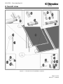
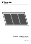
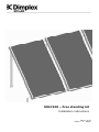
SOLAR
SOLC220 – Free standing kit
Installation instructions
Page 1 of 20
ST0117 - C – 08/09
SOLC220 - Free standing kit
SOLAR
0 Overall view
Figure 1 – Overall view of installation method
Page 2 of 20
ST0117 – C 08/09
SOLC220 - Free standing kit
1 Contents
SOLAR
0 OVERALL VIEW
2
1 CONTENTS
3
2 BEFORE YOU START
4
GENERAL
COMPETENCE
HEALTH AND SAFETY
RISK ASSESSMENT
TOOLS REQUIRED
EARTHING AND LIGHTENING PROTECTION
4
4
4
5
5
5
3 SCOPE OF DELIVERY
6
4 PRODUCT FEATURES AND DESCRIPTIONS
7
5 COLLECTOR CONNECTIONS
8
5.1 SINGLE COLLECTOR VERTICAL CONNECTION
5.2 MULTIPLE COLLECTOR VERTICAL CONNECTION
8
9
6 INSTALLATION
10
7 OPERATION
20
8 MAINTENANCE
20
9 DECOMMISSIONING
20
10 TECHNICAL DATA
20
Page 3 of 20
ST0117 – C 08/09
SOLC220 - Free standing kit
2 Before you start
SOLAR
General
Thank you for choosing a Dimplex product. We ensure you that every effort has been
made at the design, manufacture and delivery stages to produce a product with superior quality. We will provide you with the best possible support throughout the product’s
lifespan.
As part of ongoing product development and improvement Dimplex reserves the right to
undertake changes to the product without prior notice. Great care has been taken to
ensure this manual was correct at the time of print. Should you however discover any
issues with the information contained therein please do not hesitate to contact your
vendor.
We strongly recommend reading the whole contents of this manual before commencing
the work.
Competence
Dimplex products have been designed and manufactured to the current relevant standards and under stringent quality control. It is therefore imperative that the product is
only installed by a:
- trained and
- competent
person as defined in the relevant regulations. Dimplex does not accept any liability for
damage done to persons or property resulting from undue handling and usage of this
product.
All regulations current at the time of installation are to be considered alongside the content of this manual as they form the code of best practice.
The warranty of this product is linked to the ability to prove that the product was installed, commissioned and maintained:
- by a competent person
- in accordance with Dimplex instructions and the current relevant regulations and legislation
- the product being registered with Dimplex at the time of installation using the form in
the Dimplex On Site Guide
- records showing the date of maintenance in accordance with the maintenance schedule as detailed in the On Site Guide
Health and Safety
The installation of this product is subject to the Health and Safety at Work Act. It is
your responsibility to ensure that the transport, storage, installation and operation of
the product is carried out in a safe manner.
Dimplex will not accept any liability due to damage caused to people or property resulting from negligence or not adhering to the relevant Health and Safety practises.
Page 4 of 20
ST0117 – C 08/09
SOLC220 - Free standing kit
Risk assessment
SOLAR
The compilation of a risk assessment is strongly recommended before installing the
product. The following areas require particular consideration in addition to the information required by the Health and Safety at Work Act.
- scalding: where appropriate or required by law a thermostatic mixing valve is to be
fitted to the hot water outlet of the cylinder
- explosion: the unit is fully equipped with all relevant safety equipment to comply with
current regulations. The correct design and function has been verified by independent
third party testing. The correct application thereof is the responsibility of the competent installer.
- water borne organisms (i.e. Legionella): if applicable a risk assessment should be
carried out following the recommendations outlined in the Approved Code of Practise
L8.
- the user preference must be considered when commissioning the system, in particular
when adjusting the solar and auxiliary system temperature and timer settings.
Tools Required
-
2 people required for installation
Cordless drill
10mm wood or masonry drill bit
13mm socket wrench
Spanners 13/17mm
Measuring Tape
Earthing and Lightening Protection
If a lightening arrester is available, the collector frame should be connected to it. This
may be preformed using the collector frame, because the slot for mounting on the reverse side of the collector is ideally suited for fixing a thick cable. If no arrester is available, the potential equalization is carried out using a connection of a cable at the
tube(s) which are led in the building. Please consult local regulations to ensure adherence.
Pipe Work
The pipe work from the collector to the pump unit and from the pump unit to the cylinder is to be all metal. The joints have to be high temperature resistant (compression or
high temperature flat seal). For more information please see Technical Manual – Complete guide to Dimplex Solar, ST0133.
Page 5 of 20
ST0117 – C 08/09
SOLC220 - Free standing kit
SOLAR
3 Scope of delivery
Please check the contents and the condition of your delivery before signing the delivery
documentation against the content shown in Table 1 below and mark as appropriate.
Contact your supplier immediately for any missing or damaged parts. Claims for missing
of damaged parts after signing for the delivery documentation will not be accepted.
Table 1 – Scope of delivery
Page 6 of 20
ST0117 – C 08/09
SOLC220 - Free standing kit
4 Product features and descriptions
SOLAR
The Dimplex Solar Free standing kit offers a simple and secure method of securing the
SOLC220 solar collectors to a flat roof or any other flat mounting area. The collectors
can be installed at angles from 45° to 60° with the basic kit. Shorter rear struts are
available expanding the installation angles to 25° at the lower end.
Due to the flexible connections between the collectors up to 10 collectors can be directly
mounted together. Should more than 10 collectors be required the collector array has to
be split into fields which are connected in parallel to each other.
Figure 2 Single collector and two collector installations
The area required (A x B) to install the free standing collector or collector array can be
easily calculated from the formula, B = 1085mm + (n-1)1240mm where n represents the number of collectors from 1 to 10, A and C are read from table 2.
C
B
A
Figure 3 – Space requirements for free standing installation
Table 2 – Space requirements for free standing installation
Page 7 of 20
ST0117 – C 08/09
SOLC220 - Free standing kit
5 Collector connections
SOLAR
Because of its 4 connections, the collector offers a wide choice of connection options.
Ensure that no part of the collector array or collector in the array is short circuited by
following these instructions.
When planning the collector array, the position of the various connection parts must be
in accordance with the diagrams, also pay attention to the position of the highlighted
sensor pockets.
Table 3 illustrates the components required to make all the collector connection.
Table 3 - Collector connection components
5.1 Single collector vertical connection
When installing a single collector installation, there are two connection options available.
Choice of connection option will be determined by suitability and location of the components in the solar system to one another, (pipe runs etc usually determine the choice).
Figure 2 illustrates the left hand side connection option and the right hand side connection options that are applicable only to a single vertical collector connection.
Figure 2 – Left hand side and right hand side connection options for single collector only
Page 8 of 20
ST0117 – C 08/09
SOLC220 - Free standing kit
5.2 Multiple collector vertical connection
SOLAR
When installing multiple collectors, (2 up to 10), component 10.1 is used to connect one
collector to the next. The flow and return connections must be at diagonals to one another as illustrated in Figure 3 and Figure 4. These diagrams highlight the two connection options available when connecting multiple collectors vertically in an array. When
connecting up to five collectors in an array the flow and return connections can be made
on the same side.
Figure 3 - Multiple collector vertical connection, Option 1
The location of the sensor pockets should be noted upon installation, which is highlighted in Figure 3 and Figure 4. The orientation of the middle collector(s) is unimportant. The collector temperature senor should be installed at the collector flow, (flow to
the cylinder).
Figure 4 – Multiple collector vertical connection, Option 2
Page 9 of 20
ST0117 – C 08/09
SOLC220 - Free standing kit
6 Installation
SOLAR
Step 1.1 Fixing
- Determine the dimensions of the whole
collector array and mark the position of
the U-pieces (3.1).
- Distance A applies to the spacing between the U-pieces of the basic kit, distance D to all extension kits.
- Dimension B relates to the distance
between the U-pieces of adjacent collectors.
- Dimension C is fixed at 1140mm.
- The measurements relate to the middle
of the U-piece components.
- It is important to remember when installing the collectors, they must be installed from left to right only, (when
facing the array from surface exposed
to the sun).
Step 1.2 Fixing
- Before drilling the holes in the surface
for the U-pieces, check the spacing
using the diagonals.
- Diagonals E and F must be of equal
length, as must diagonals G an H.
- Next, drill with the ø10 mm drill bit at
the marked positions.
- If drilling is not permitted on a flat
roof due to the leak-tightness of the
roof, appropriate concrete slabs or a
similar material must be used as a
foundation.
Page 10 of 20
ST0117 – C 08/09
SOLC220 - Free standing kit
SOLAR
Step 1.3 Fixing
- Use the rawlplugs (3.4) and fasten
the U-pieces (3.1) with washers (3.3)
and bolts (3.2).
- If U-rails are being used, also fasten
these with washers (3.3) and bolts
(3.2).
Step 1.4 Fixing
- Attach the supporting tube (2) to the
rear U-pieces (3.1) with an M10 hexagonal bolt (3.6), spring washer (3.7)
and hexagonal nut (3.8).
- Put the protective cap (3.5) on the
supporting tube.
- Screw the bolt tight enough so that the
supporting tubes can be mounted upright.
Step 2.1 Collector
- Lift two of the square nuts in the slot
on the back of the collector (1) with
a screwdriver and hold them with the
installation aid (4.4).
- Using the installation aid, the nut can
easily be positioned for further installation of the T-pieces when the collector (1) has been erected.
Page 11 of 20
ST0117 – C 08/09
SOLC220 - Free standing kit
SOLAR
Step 2.2 Collector
- Preassemble four T-pieces (4.1) for
each collector with M8 hexagonal bolts
(4.2) on the square nuts in the slot on
the rear of the collector (1).
- To do so, align the first square nut with
the help of the long side of the installation aid (4.4).
- Attach the T-piece and screw in a hexagonal bolt.
- Align the second square nut by turning
the installation aid and screw in another hexagonal bolt.
Step 2.3 Collector
- Determine the definitive lower spacing
of the T-pieces (4.1) on the collector
(1).
- To do so, make sure the spacing G of
40 mm from the bottom edge of the
collector for the lower T-pieces is observed.
- Screw the T-pieces tightly.
- To avoid damage to the collector, the
spacing G of 40 mm must be observed.
Page 12 of 20
ST0117 – C 08/09
SOLC220 - Free standing kit
SOLAR
Step 2.4 Collector
- Determine the definitive upper spacing
of the T-pieces (4.1) on the collector.
- The mounting angle is determined by
the spacing H between the two Tpieces.
- Screw the T-pieces tightly.
- For mounting options 30°, 35° and 40°
component 2.1 (rear strut 740mm
long) must be used.
Step 2.5 Collector
- Punch the two drainage holes at each
BOTTOM corner of the collector, according to how it is mounted, with the
aid of a slotted screwdriver.
- To do so, punch at the bottom edge.
- To ensure that water can drain properly
from the collector, it is absolutely essential that all drainage holes are
punched at the bottom corners (depending on how the collector is
mounted on the kit).
Page 13 of 20
ST0117 – C 08/09
SOLC220 - Free standing kit
SOLAR
Step 2.6 Collector
- Have the M10 hexagonal bolts (3.6),
large spacer sleeves (3.9), spring
washers (3.7) and M10 hexagonal nuts
(3.8) ready for fastening the collector.
- If laying the collector on the surface
for a short time, it may be necessary
to use an underlay to avoid damage to
the frame.
- The help of a second person is required
to position the collector and fix it in
place.
The collector must NOT be rested on
the back pane or the glass. It must
always be supported on the frame!
Step 2.7 Collector
The above step (Step 2.7) gives an overview of the collector fixings and connections.
The highlighted areas (1, 2, 3 and 4) are presented in more detail below in the next
five steps.
Page 14 of 20
ST0117 – C 08/09
SOLC220 - Free standing kit
SOLAR
Step 2.7.1 Collector
- Attach the collector (1) to the front Upieces (3.1).
- To do so, position the collector with the
help of a second person.
- Attach the T-pieces (4.1) to the Upieces using M10 hexagonal bolts (3.6),
large spacer sleeves (3.9), spring washers (3.7) and M10 hexagonal nuts (3.8).
Step 2.7.2 Collector
- Slowly tilt the collector (1) towards
the supporting tubes (2).
- Attach the T-pieces using M10 hexagonal bolts (3.6), large spacer
sleeves (4.3), spring washers (3.7)
and M10 hexagonal nuts (3.8).
- Fasten all four T-pieces in place by
tightening the M10 hexagonal bolts.
Page 15 of 20
ST0117 – C 08/09
SOLC220 - Free standing kit
SOLAR
Step 2.7.3 Connections
- Fit the insert rings onto the corrugated
interconnection component.
- Ensure two insert rings are inserted
into the 4th and 5th trough from both
ends of the component.
- The insert rings must be securely
pressed together around the circumference of the corrugated pipe.
- Coat the o-rings of the corrugated pipe
compensators (6.1) with grease (5.5)
and fit one of them in each of the connection of the pre-assembled collector.
- The compensators must be slid into the
connections of the collector until the
first insert ring is flush with the end of
the collector connection.
O-rings
Free corrugation
2 x insert rings
- Ensure that the o-rings sit tight in their
fittings.
Step 2.7.4 Collector
- Fix the upper T-pieces (4.1) to the supporting tubes (2).
- To do so, preassemble the T-pieces
using M10 hexagonal bolts (3.6), large
spacer sleeves (4.3), spring washers
(3.7) and M10 hexagonal nuts (3.8).
- Keep supporting the collector until all
M10 hexagonal bolts have been attached.
Page 16 of 20
ST0117 – C 08/09
SOLC220 - Free standing kit
SOLAR
Step 2.7.5 Collector
- Preassemble the lower T-pieces to the
U-pieces using M10 hexagonal bolts
(3.6), large spacer sleeves (3.9),
spring washers (3.7) and M10 hexagonal nuts (3.8).
- Keep supporting the collector until all
M10 hexagonal bolts have been attached.
- Screw tight all M10 hexagonal bolts
with spring washers and M10 hexagonal nuts.
Step 3.1 Connections
The remaining interconnections
made, ensuring that;
are
- Insert rings (6.2) are placed in the 4th
and 5th trough of the corrugated pipe
(6.1), counted from the end, on the
side faced next to the collector.
- The insert rings must be securely
pressed around the circumference of
the corrugated pipe.
- Next insert the corrugated pipe (6.1)
until blocked by the 1st insert ring.
Step 3.2 Connections
- Pull clamps (6.3) over the collector
connections and the outer insert rings,
then press with adjustable pliers or
grips and fix it using the screw.
- Make sure that the outer insert ring is
completely covered by the clamp.
Page 17 of 20
ST0117 – C 08/09
SOLC220 - Free standing kit
SOLAR
Step 3.3 Connections
- Coat in O-rings of the connection pipe
(5.1) with the grease (5.5).
- Position the insert rings (5.6) in the 4th
and 5th trough of the corrugated pipe,
counted from the end.
- Next insert the connection pipe into the
collector connection until the outer insert ring is flush with the outside of the
collector tulip.
Step 3.4 Connections
- Pull clamps (5.3) over collector connections and outer insert ring, using pliers
or an adjustable spanner press the
clamp closed so the screw secures it.
- Make sure the outer insert ring is covered by clamp.
Step 3.5 Connections
- Coat the o-rings on the end piece (5.2)
with grease (5.5).
- Insert the end piece tightly into the
collector connection.
- Next pull the clamp (5.3) over collector
connections and outer insert rings.
- Press the clamp with pliers or an adjustable spanner so the screw secures
the clamp in position.
Page 18 of 20
ST0117 – C 08/09
SOLC220 - Free standing kit
SOLAR
Step 4.1 Sensor
- Carefully remove the grommet from the
collector housing.
- Slide the grommet over the temperature sensor (included with the solar
controller).
- Insert the temperature sensor fully into
the immersion sleeve. Seal the collector
frame using grommet. Ensure correct
placement of the grommet.
Step 5.1
- Please refer to the ‘On site guide’ for
details on pressure testing, testing for
leaks and proper maintenance of the
system.
- Upon completion of testing for leaks,
please ensure that all the pipe work is
properly insulated.
Page 19 of 20
ST0117 – C 08/09
SOLC220 - Free standing kit
7 Operation
SOLAR
Although there are no operational components in the free standing kit, the fixings
should be tightened and double checked prior to commissioning of the system.
Please refer to the On Site Guide for guidance on how to commission and operate the
solar system.
8 Maintenance
Risk of scalding! Before carrying out any maintenance work on the system ensure that
it is safe to do so. The solar system must be decommissioned before work can be carried out.
Refer to the On Site Guide for a maintenance schedule of the complete system. However some basic checks can be made, for example, check for leaks at the collector connections and other connections in the system. Also ensure pipe insulation is intact and
in good condition.
9 Decommissioning
Risk of scalding! Before carrying out any decommissioning work on the free standing kit,
please ensure the solar system has been decommissioned.
If the product is being recycled, local waste disposal laws must be adhered to.
10 Technical Data
Page 20 of 20
ST0117 – C 08/09