1
EDUS301214-N
Installation
RWEYQ-PTJU
3 phase
208/230V, 60Hz
RWEYQ-PYDN
3 phase
460V, 60Hz
EDUS301214-N
Installation of
Outside Units
1. Center of Gravity .........................................................................................2
2. Installation Manual ......................................................................................3
2.1 RWEYQ-PTJU/RWEYQ-PYDN.................................................................... 3
2.2 RWEYQ-PTJU (In case of manufacturing code: RWEYQ-PTJU9) ............ 27
3. Instructions for Antifreeze Usage ..............................................................49
4. REFNET Pipe System...............................................................................50
4.1
4.2
4.3
4.4
Layout Example.......................................................................................... 50
Max. Refrigerant Piping Length.................................................................. 52
Field Refrigerant Piping.............................................................................. 53
REFNET Joints and Headers ..................................................................... 54
5. REFNET Joint and Header .......................................................................56
5.1 REFNET Joint (Branch Kit) ........................................................................ 56
5.2 REFNET Header (Branch Kit) .................................................................... 64
5.3 Outside Unit Multi Connection Piping Kit.................................................... 72
6. Field Setting ..............................................................................................80
6.1 RWEYQ-PTJU/RWEYQ-PYDN.................................................................. 80
6.2 RWEYQ-PTJU (In case of manufacturing code: RWEYQ-PTJU9) ............ 87
Installation of Outside Units
1
Center of Gravity
EDUS301214-N
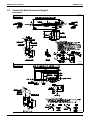
1. Center of Gravity
RWEYQ72PTJU / RWEYQ84PTJU
(384)
(1000)
Unit: in. (mm)
(375)
(167)
(744)
(400)
C: 4D066040
RWEYQ72PYDN/RWEYQ84PYDN
Unit: in. (mm)
4D079929
2
Installation of Outside Units
EDUS301214-N
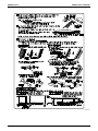
Installation Manual
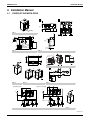
2. Installation Manual
RWEYQ-PTJU/RWEYQ-PYDN
[3]
≤13-3/4
30-11/16
7
1
7
8
7
6
≥15-3/8
9
≥13/16
2 (PTJU)
≥35-7/16
≥13/16
∗10
5
≥60
≥60
≥60
5
≥13/16
39-3/8
≥40
≥40
≥13-3/4
[4]
4
0
≥4
≥13/16
6
9
2
≥60
6
≥11-13/16
1
3
8
21-5/8 ≥19-11/16
figure 1
2
9
9
8
2 (PYDN)
≥19-11/16
2
≥13/16
1
≥35-7/16
2.1
8
≥3-15/16
≤9-13/16
(in.)
figure 3
figure 2
3-1/8
3
12
3-1/8
13
15-3/4
2
29-5/16
1
1
2
4
14
≤15-3/4
9
6
8
60
7
3
[1]
5
15
11
10
figure 6
1
2
4
5
7
6
3
2
8
9
4
10
11
figure 4
figure 5
figure 7
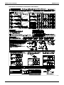
[Heat pump system]
[Heat recovery system]
3
4
3
4
1
7
2
2
2
3
10
5
4
1
7
1
8
10
5
4
9
6
figure 8
9
6
figure 9
3P153897-12X
Installation of Outside Units
3
Installation Manual
EDUS301214-N
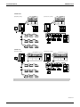
<RWEYQ-PYDN>
[Heat pump system]
[Heat recovery system]
7
7
F1 F2 F1 F2 Q1 Q2
F1 F2 F1 F2 Q1 Q2
TO IN/D UNIT TO OUT/D UNIT TO MULTI UNIT
TO IN/D UNIT TO OUT/D UNIT TO MULTI UNIT
2
2
12
ABC
12
A5P
A5P
A1P
A1P
F1 F2 F1 F2 Q1 Q2
F1 F2 F1 F2 Q1 Q2
A
A B C
1
B
C
A
A B C
C/H SELECTOR
B
C
C/H SELECTOR
4
3
F1 F2
F1 F2
F1 F2
F1 F2 F1 F2
IN/D
OUT/D.BS
F1 F2 F1 F2
IN/D
OUT/D.BS
F1 F2 F1 F2
IN/D
OUT/D.BS
8
9
10
4
6
5
F1 F2
F1 F2
F1
F2
F1
F2
F1
F1
F2
F1
F2
F2
F1 F2
F1
F2
11
6
F1 F2
F1 F2
F1 F2
<RWEYQ-PTJU>
[Heat pump system]
[Heat recovery system]
7
7
A
ABC
B
C
F1 F2 F1 F2 Q1 Q2
A
B
C
F1 F2 F1 F2 Q1 Q2
C/H SELECTOR
TO IN/D UNIT TO OUT/D UNIT TO MULTI UNIT
A1P
A1P
A B C F1 F2 F1 F2 Q1 Q2
A B C F1 F2 F1 F2 Q1 Q2
C/H SELECTOR
1
TO IN/D UNIT TO OUT/D UNIT TO MULTI UNIT
2
2
4
3
F1 F2
F1 F2
F1 F2
F1 F2 F1 F2
IN/D
OUT/D.BS
F1 F2 F1 F2
IN/D
OUT/D.BS
F1 F2 F1 F2
IN/D
OUT/D.BS
8
9
10
4
6
5
F1 F2
F1 F2
F1
F2
F1
F2
F1
F1
F2
F1
F2
F2
F1 F2
F1
F2
11
6
F1 F2
F1 F2
F1 F2
figure 10
3P153897-12X
4
Installation of Outside Units
EDUS301214-N
Installation Manual
<RWEYQ-PYDN>
<RWEYQ-PYDN>
1
2
3
6
6
Q1 Q2
Q1 Q2
A1P
4
2
X1M
A1P
F1 F2 F1 F2 Q1 Q2
5
6
F1 F2 F1 F2 Q1 Q2
5
X2M
1
A5P
A B C
1
4
2
X3M
3 4
A5P
A
B
C
3
3
9
8
7
<RWEYQ-PTJU>
<RWEYQ-PTJU>
1
2
3
6
6
Q1 Q2
Q1 Q2
A1P
A1P
A
4
5
6
A B C F1 F2 F1 F2 Q1 Q2
X1M
B
C
X2M
1
1
4
X3M
3 4
2
3
9
7
2
F1 F2 F1 F2 Q1 Q2
8
figure 11
figure 12
1
2
3
1
2
4
LOW NOISE
F1 F2
TO OUT/D UNIT
F1 F2
TO OUT/D UNIT
F1 F2
TO OUT/D UNIT
F1 F2
F1 F2
6
5
F1 F2
F1 F2
F1 F2
7
figure 13
figure 14
12
11
13
14
O
U
T
A1P
15
TO IN/D
UNIT
F1 F2
1
F1 F2
ON
DS1
OFF
1
I
N
2
2
3
4
7
4
9
3
6
F1 F2
P1 P2
P1 P2
10
1
5
8
figure 15
figure 16
3P153897-12X
Installation of Outside Units
5
Installation Manual
EDUS301214-N
<RWEYQ-PTJU>
<RWEYQ-PYDN>
O
U
T
A1P
O
U
T
A1P
ON
ON
DS1
OFF
1
I
N
2
3
DS1
OFF
ABC
4
1
I
N
2
3
1
4
6
2
3
A5P
ABC
2
4
ABC
ABC
3
1
figure 17
figure 18
<RWEYQ-PYDN>
<RWEYQ-PTJU>
<RWEYQ-PTJU>
22
2
1
11
7
77
88
8
99
9
5
5
1
5
5
4
4
4
3
3
3
10
10
10
11
11
11
6
6
6
figure 19
[Heat recovery system]
[Heat pump system]
1
2
3
10
7
8
9
4
[13]
4
14
5
11
15
5
16
∗6
∗17
12
figure 20
4
1
1
2
3
3
B
5
[A-arrow view]
figure 21
2
A
[B-arrow view]
figure 22
3P153897-12X
6
Installation of Outside Units
EDUS301214-N
Installation Manual
(Fig. A)
(Fig. B)
C
1
2
1
(Fig. C)
5
D
≤ ±15
4
3
3
[C-arrow view]
[D-arrow view]
figure 23
[Heat pump system]
11
10
1
10
12
9
R410A
7
3
4
2
15
16
5
6
18
[Heat recovery system]
14
13
1
10
10
12
9
R410A
7
3
4
2
8
15
17
5
6
18
figure 24
4
[Heat pump system]
3
2
[Heat recovery system]
1
1
2
1
5
5
2
3
2
3
6
4
4
5
1
figure 25
figure 26
4 3
figure 27
3P153897-12X
Installation of Outside Units
7
Installation Manual
EDUS301214-N
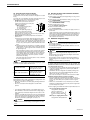
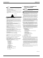
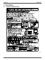
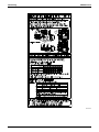
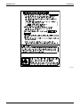
1. SAFETY CONSIDERATIONS
Read these SAFETY CONSIDERATIONS for Installation carefully
before installing an air conditioner or heat pump. After completing the
installation, make sure that the unit operates properly during the startup operation.
Instruct the customer on how to operate and maintain the unit. Inform
customers that they should store this Installation Manual with the
Operation Manual for future reference.
Always use a licensed installer or contractor to install this product.
Improper installation can result in water or refrigerant leakage, electrical shock, fire, or explosion.
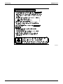
Meanings of DANGER, WARNING, CAUTION, and NOTE Symbols:
DANGER .............. Indicates an imminently hazardous
situation which, if not avoided, will
result in death or serious injury.
WARNING ............ Indicates a potentially hazardous
situation which, if not avoided, could
result in death or serious injury.
CAUTION ............. Indicates a potentially hazardous
situation which, if not avoided, may
result in minor or moderate injury. It
may also be used to alert against
unsafe practices.
NOTE .................. Indicates situations that may result
in equipment or property-damage
accidents only.
DANGER
• Refrigerant gas is heavier than air and replaces oxygen. A massive leak will result in oxygen depletion,
especially in basements, and an asphyxiation hazard
will result in serious injury or death.
• Do not ground units to water pipes, gas pipes,
telephone wires, or lightning rods as incomplete
grounding will result a severe shock hazard resulting
in severe injury or death. Additionally, grounding to
gas pipes will result a gas leak and potential
explosion resulting in severe injury or death.
• If refrigerant gas leaks during installation, ventilate
the area immediately. Refrigerant gas will result in
producing toxic gas if it comes into contact with fire.
Exposure to this gas will result in severe injury or
death.
• After completing the installation work, check that the
refrigerant gas does not leak throughout the system.
• Do not install unit in an area where flammable
materials are present due to risk of explosions that
will result in serious injury or death.
• Safely dispose all packing and transportation
materials in accordance with federal/state/local laws
or ordinances. Packing materials such as nails and
other metal or wood parts, including plastic packing
materials used for transportation will result in
injuries or death by suffocation.
• Only qualified personnel must carry out the installation
work. Installation must be done in accordance with this
8
installation manual. Improper installation could result
in water leakage, electric shock, or fire.
• When installing the unit in a small room, take measures
to keep the refrigerant concentration from exceeding
allowable safety limits. Excessive refrigerant leaks, in
the event of an accident in a closed ambient space,
could result in oxygen deficiency.
• Use only specified accessories and parts for
installation work. Failure to use specified parts could
result in water leakage, electric shocks, fire, or the
unit falling.
• Install the air conditioner or heat pump on a
foundation strong enough that it can withstand the
weight of the unit. A foundation of insufficient
strength could result in the unit falling and causing
injuries.
• Take into account strong winds, typhoons, or
earthquakes when installing. Improper installation
could result in the unit falling and causing accidents.
• Make sure that a separate power supply circuit is
provided for this unit and that all electrical work is
carried out by qualified personnel according to local.
state, and national regulations. An insufficient power
supply capacity or improper electrical construction
could result in electric shocks or fire.
• Make sure that all wiring is secured, that specified
wires are used, and that no external forces act on the
terminal connections or wires. Improper
connections or installation could result in fire.
• When wiring, position the wires so that the terminal
box lid can be securely fastened. Improper
positioning of the terminal box lid could result in
electric shocks, fire, or the terminals overheating.
• Before touching electrical parts, turn off the unit.
• This equipment can be installed with a Ground-Fault
Circuit Breaker (GFCI). Although this is a recognized
measure for additional protection, with the earthing
system in North America, a dedicated GFCI is not
necessary.
• Securely fasten the unit terminal cover (panel). If the
terminal cover/panel is not installed properly, dust or
water may enter the condenser unit and could result
in fire or electric shock.
• When installing or relocating the system, keep the
refrigerant circuit free from substances other than
the specified refrigerant (R-410A) such as air. Any
presence of air or other foreign substance in the
refrigerant circuit could result in abnormal pressure
rise or rupture, resulting in injury.
• Do not change the setting of the protection devices.
If the pressure switch, thermal switch, or other
protection device is shorted and operated forcibly, or
Installation of Outside Units
EDUS301214-N
parts other than those specified by Daikin are used,
fire or explosion could result.
• Do not touch the switch with wet fingers. Touching a
switch with wet fingers may result in electric shock.
• Do not allow children to play on or around the unit or
it may result in injury.
• The heat exchanger fins are sharp enough to cut,
and may result in injury if improperly used. To avoid
injury wear gloves or cover the fins while working
around them.
• Do not touch the refrigerant pipes during and
immediately after operation as the refrigerant pipes
may be hot or cold, depending on the condition of
the refrigerant flowing through the refrigerant
piping, compressor, and other refrigerant cycle
parts. It may result in your hands getting burns or
frostbite if you touch the refrigerant pipes. To avoid
injury, give the pipes time to return to normal
temperature or, if you must touch them, be sure to
wear proper gloves.
• Install drain piping to proper drainage. Improper
drain piping may result in water leakage and
property damage.
• Insulate piping to prevent condensation.
• Be careful when transporting the product.
• Do not turn off the power immediately after stopping
operation. Always wait for at least 5 minutes before
turning off the power. Otherwise, water leakage may
result.
• Do not use a charging cylinder. Using a charging
cylinder may cause the refrigerant to deteriorate.
• Refrigerant R-410A in the system must be kept clean,
dry, and tight.
(a) Clean and Dry -- Foreign materials (including
mineral oils such as SUNISO oil or moisture)
should be prevented from getting into the
system.
(b) Tight -- R-410A does not contain any chlorine,
does not destroy the ozone layer, and does not
reduce the earth’s protection again harmful
ultraviolet radiation. R-410A can contribute to
the greenhouse effect if it is released. Therefore
take proper measures to check for the tightness
of the refrigerant piping installation. Read the
chapter Refrigerant Piping and follow the
procedures.
• Since R-410A is a blend, the required additional
refrigerant must be charged in its liquid state. If the
refrigerant is charged in a state of gas, its
composition can change and the system will not
work properly.
Installation of Outside Units
Installation Manual
• The indoor unit is for R-410A. See the catalog for
indoor models that can be connected. Normal
operation is not possible when connected to other
units.
• Remote controller (wireless kit) transmitting
distance can be shorter than expected in rooms with
electronic fluorescent lamps (inverter or rapid start
types). Install the indoor unit far away from
fluorescent lamps as much as possible.
• Indoor units are for indoor installation only. Outdoor
units can be installed either outdoors or indoors.
This unit is for indoor use.
• Do not install the air conditioner or heat pump in the
following locations:
(a) Where a mineral oil mist or oil spray or vapor is produced, for
example, in a kitchen.
Plastic parts may deteriorate and fall off and thus may result in
water leakage.
(b) Where corrosive gas, such as sulfurous acid gas, is produced.
Corroding copper pipes or soldered parts may result in refrigerant
leakage.
(c) Near machinery emitting electromagnetic waves.
Electromagnetic waves may disturb the operation of the control
system and cause the unit to malfunction.
(d) Where flammable gas may leak, where there is carbon fiber, or
ignitable dust suspension in the air, or where volatile flammables
such as thinner or gasoline are handled. Operating the unit in
such conditions may result in a fire.
• Take adequate measures to prevent the condenser
unit from being used as a shelter by small animals.
Small animals making contact with electrical parts
may result in malfunctions, smoke, or fire. Instruct
the customer to keep the area around the unit clean.
• Install the power supply and control wires for the
indoor and outdoor units at least 3.5 feet away from
televisions or radios to prevent image interference or
noise. Depending on the radio waves, a distance of 3.5
feet may not be sufficient to eliminate the noise.
• Dismantling the unit, treatment of the refrigerant, oil
and additional parts must be done in accordance
with the relevant local, state, and national
regulations.
• Do not use the following tools that are used with
conventional refrigerants: gauge manifold, charge
hose, gas leak detector, reverse flow check valve,
refrigerant charge base, vacuum gauge, or
refrigerant recovery equipment.
• If the conventional refrigerant and refrigerator oil are
mixed in R-410A, the refrigerant may result in
deterioration.
• This air conditioner or heat pump is an appliance
that should not be accessible to the general public.
• As design pressure is 478 psi, the wall thickness of
field-installed pipes should be selected in
accordance with the relevant local, state, and
national regulations.
9
Installation Manual
2.
EDUS301214-N
INTRODUCTION
This installation manual concerns VRV inverters of the Daikin
RWEYQ-P series. These units are designed for indoor installation and
used for cooling and heat pump applications.
The RWEYQ-P units can be combined with Daikin VRV series indoor
units for air conditioning purposes.
The present installation manual describes the procedures for unpacking, installing and connecting the RWEYQ-P units. Installation of the
indoor units is not described in this manual. Always refer to the installation manual supplied with these units for their installation.
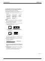
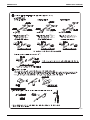
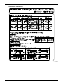
2-3 Standard supplied accessories
2-1 Combination
The indoor units can be installed in the following range.
• Always use appropriate indoor units compatible with R410A.
To learn which models of indoor units are compatible with
R410A, refer to the product catalogs.
• Total capacity/quantity of indoor units
¢Outside unit²
¢Total capacity index of indoor units² ¢Total quantity of indoor units²
RWEYQ72PYDN/TJU ....... 36 ~ 93.5
12 units
RWEYQ84PYDN/TJU ....... 42 ~ 109
14 units
RWEYQ144PYDN/TJU ..... 72 ~ 187
20 units
RWEYQ168PYDN/TJU ..... 84 ~ 218
20 units
RWEYQ216PYDN/TJU ... 108 ~ 280
22 units
RWEYQ252PYDN/TJU ... 126 ~ 327.5
32 units
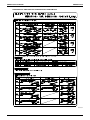
2-2 Standard operation limit
Cooling
Accessory pipes
Name
For discharge
gas
For suction
gas (1)
For suction
gas (2)
Clamp (A)
Clamp (B)
1 pc.
1 pc.
1 pc.
7 pcs.
2 pcs.
Quantity
(Note)
Shape
Quantity
2 pcs.
2 pcs.
[Others]
• Installation manual
• Operation manual
Shape
Heating
Black
White
Conduit mounting plate
A
120
120
110
110
100
100
90
90
80
80
70
70
60
60
50
(Refer to figure 1)
1. • Operation manual
• Installation manual
• Clamp (A)
• Clamp (B)
• Conduit mounting plate
2. Accessory pipes
• For discharge gas
• For suction gas (1)
• For suction gas (2)
50
50
60
70
80
90
50
60
70
80
90
B
C
¢In case of antifreeze usage²
Cooling
A
Heating
NOTE
The accessory pipe for discharge gas is used for the heat recovery system. (Not used for the heat pump system.)
2-4 Option accessories
A
120
110
110
100
100
90
90
80
To install the above outside units, the following optional parts are also
required.
• Refrigerant branching kit
(For R410A only: Always use an appropriate kit dedicated for your
system.)
80
70
¢Heat pump system²
70
60
60
50
50
40
40
30
30
20
20
10
50
60
70
80
90
REFNET header KHRP26M22H9 KHRP26M33H9 KHRP26M72H9 KHRP26M73HU9
REFNET joint
KHRP26A22T9 KHRP26A33T9 KHRP26M72TU9 KHRP26M73TU9
¢Heat recovery system ..... For 3-tube piping²
REFNET header
REFNET joint
KHRP25M33H9 KHRP25M72H9 KHRP25M73HU9
KHRP25A22T9 KHRP25A33T9 KHRP25M72TU9 KHRP25M73TU9
¢Heat recovery system ..... For 2-tube piping²
50
B
A
B
C
• Make sure that the following accessories are included.
(Check by removing the front panel.)
Name
The figures below assume following operating conditions for indoor and
outside units:
Equivalent pipe length ..................................................... 25 ft
Level difference.................................................................. 0 ft
A
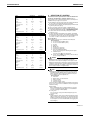
• Operation range of water flow rate is 13.2~39.6 gpm. (21.2~39.5 gpm
in case of antifreeze usage.)
• The unit is designed for the following operation range:
Entering water temperature: 67~95°F
Water flow rate: 16 gpm or more
s#ANBEEXPANDEDDOWNTO&INHEATINGAND&INCOOLING!PPLICATION
RULESAPPLYCONTACTYOURLOCAL$AIKIN3ALESOFFFORDESIGNASSISTANCE
0RIOR$AIKINDEALERCONSULATIONISNECESSARYFORHEATSOURCEEQUIPMENT
• Hold ambient temperature at 35~°F
Heat-release from the unit: 2 Btu.
It is therefore recommended to always ventilate the room.
Entering water temperature (°F)
Indoor temperature (°FWB)
Indoor temperature (°FDB)
Range for continuous operation
Range for operation
Range for pull down operation
Range for warming up operation
60
70
80
90
C
REFNET header KHRP26M22H9 KHRP26M33H9 KHRP26M72H9 KHRP26M73HU9
REFNET joint
KHRP26A22T9 KHRP26A33T9 KHRP26M72TU9 KHRP26M73TU9
• Outside unit multi connection piping kit
(For R410A only: Always use an appropriate kit dedicated for
your system.)
Number of outside units
connected
2 units
3 units
Heat pump system
BHFP22MA56U
BHFP22MA84U
Heat recovery system
BHFP26MA56U
BHFP26MA84U
To select an optimum kit, refer to “9. REFRIGERANT PIPING”
3P153897-12X
10
Installation of Outside Units
EDUS301214-N
Installation Manual
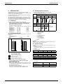
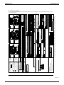
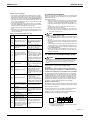
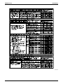
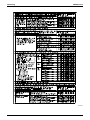
2-5 Technical specifications (1)
General
RWEYQ72PYDN/TJU
RWEYQ84PYDN/TJU
Nominal cooling capacity (2) (MBH)
72
84
Nominal heating capacity (3) (MBH)
81
94.5
Nominal input cooling / heating (4) (kW)
4.20 / 4.00
5.60 / 5.40
Dimensions HxWxD
(inch)
Weight (YDN/TJU)
(lbs)
39-3/8×30-3/4×21-11/16
343/330
343/330
Connections
Compressor
RWEYQ72PYDN/TJU
RWEYQ84PYDN/TJU
Oil type
Synthetic (ether) oil
Synthetic (ether) oil
Crankcase heater
(W)
Refrigerant type
Refrigerant charge
(inch)
3/8
3/8
Compressor
refrigerant gas pipe
(inch)
3/4
7/8
refrigerant discharge gas pipe (5) (inch)
5/8
3/4
1-1/4FPT
female Thread
1-1/4FPT
female Thread
Crankcase heater
(W)
Refrigerant type
Refrigerant charge
33
R410A
R410A
9.9
11.5
RWEYQ144PYDN/TJU
RWEYQ168PYDN/TJU
Synthetic (ether) oil
Synthetic (ether) oil
(lbs)
Oil type
refrigerant liquid pipe
33
(lbs)
(33)×2
(33)×2
R410A
R410A
(9.9)×2
(11.5)×2
RWEYQ216PYDN/TJU
RWEYQ252PYDN/TJU
Synthetic (ether) oil
Synthetic (ether) oil
Water piping connections
Inlet pipe
(inch)
Outlet pipe
(inch)
1-1/4FPT
female Thread
1-1/4FPT
female Thread
Drain pipe
(inch)
1/2FPS
female Thread
1/2FPS
female Thread
RWEYQ144PYDN/TJU
RWEYQ168PYDN/TJU
Nominal cooling capacity (2) (MBH)
144
168
Nominal heating capacity (3) (MBH)
162
189
Nominal input cooling / heating (4) (kW)
8.40 / 8.00
11.20 / 10.80
General
Dimensions HxWxD
(inch)
Weight (YDN/TJU)
(lbs)
(39-3/8×30-3/4×21-11/16)×2
343×2/330×2
343×2/330×2
Connections
refrigerant liquid pipe
(inch)
1/2
5/8
refrigerant gas pipe
(inch)
1-1/8
1-1/8
7/8
7/8
(1-1/4FPT)×2
female Thread
(1-1/4FPT)×2
female Thread
refrigerant discharge gas pipe (5) (inch)
Water piping connections
Inlet pipe
Compressor
Oil type
Crankcase heater
(W)
Refrigerant type
Refrigerant charge
(lbs)
Outlet pipe
(inch)
(1-1/4FPT)×2
female Thread
(1-1/4FPT)×2
female Thread
Drain pipe
(inch)
(1/2FPS)×2
female Thread
(1/2FPS)×2
female Thread
(33)×3
R410A
R410A
(9.9)×3
(11.5)×3
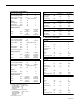
2-6 Electrical specifications
Model
RWEYQ72PYDN
RWEYQ84PYDN
3~
3~
Power supply
Phase
Frequency
(Hz)
60
60
Voltage
(V)
460
460
Voltage tolerance
(%)
±10
±10
Recommended fuses
(A)
15
15
3~
3~
Compressor
Phase
(inch)
(33)×3
Frequency
(Hz)
60
60
Voltage
(V)
460
460
Nominal running current
(A)
5.3
7.0
RWEYQ144PYDN
RWEYQ168PYDN
3~
3~
Model
Power supply
General
RWEYQ216PYDN/TJU
RWEYQ252PYDN/TJU
Nominal cooling capacity (2) (MBH)
216
252
Nominal heating capacity (3) (MBH)
243
283.5
Nominal input cooling / heating (4) (kW)
12.60 / 12.00
16.80 / 16.20
Dimensions HxWxD
(inch)
(39-3/8×30-3/4×21-11/16)×3
Weight (YDN/TJU)
(lbs)
343×3/330×3
343×3/330×3
refrigerant liquid pipe
(inch)
5/8
3/4
refrigerant gas pipe
(inch)
1-1/8
1-1/4
1
1-1/8
(1-1/4FPT)×3
female Thread
(1-1/4FPT)×3
female Thread
Connections
Phase
Frequency
(Hz)
60
60
Voltage
(V)
460
460
Voltage tolerance
(%)
±10
±10
Recommended fuses
(A)
(15)×2
(15)×2
3~
3~
Compressor
Phase
refrigerant discharge gas pipe (5) (inch)
Frequency
(Hz)
60
60
Voltage
(V)
460
460
Nominal running current
(A)
(5.3)×2
(7.0)×2
RWEYQ216PYDN
RWEYQ252PYDN
3~
3~
Water piping connections
Inlet pipe
Outlet pipe
Drain pipe
(inch)
(inch)
(1-1/4FPT)×3
female Thread
(1-1/4FPT)×3
female Thread
(inch)
(1/2FPS)×3
female Thread
(1/2FPS)×3
female Thread
(1) Refer to the engineering data book for the complete list of specifications.
(2) The normal cooling capacities are based on:
–Indoor temperature:
80°FDB / 67°FWB
–Entering water temperature: 85°F
–Leaving water temperature: 95°F
–Equivalent pipe length:
25 ft
–Level difference:
0 ft
(3) The normal heating capacities are based on:
–Indoor temperature:
70°FDB / 60°FWB
–Entering water temperature: 70°F
–Equivalent pipe length:
25 ft
–Level difference:
0 ft
(4) The nominal input includes total input of the unit: compressor and control circuit.
(5) In case of heat recovery system
Model
Power supply
Phase
Frequency
(Hz)
60
60
Voltage
(V)
460
460
Voltage tolerance
(%)
±10
±10
Recommended fuses
(A)
(15)×3
(15)×3
3~
3~
Compressor
Phase
Frequency
(Hz)
60
60
Voltage
(V)
460
460
Nominal running current
(A)
(5.3)×3
(7.0)×3
3P153897-12X
Installation of Outside Units
11
Installation Manual
EDUS301214-N
Model
RWEYQ72PTJU
RWEYQ84PTJU
Power supply
Phase
3~
3~
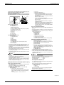
3.
SELECTION OF LOCATION
This unit does not have specifications for outdoor installation. The
unit must be installed indoors (example: machine room, …).
Paying attention to the conditions mentioned below, select the place for
installation with a prior approval of customer.
Frequency
(Hz)
60
60
Voltage
(V)
208/230
208/230
Voltage tolerance
(%)
±10
±10
Recommended fuses
(A)
40
40
2. Consider the space required for refrigerant piping work when install-
3~
3~
3. There is no danger of fire due to leakage of inflammable gas.
4. The piping length between the outside unit and the indoor unit may
Compressor
1. The foundation is strong enough to support the weight of the unit and
the floor is flat to prevent vibration and noise generation.
ing. Refer to [Necessary Space].
Phase
Frequency
(Hz)
60
60
Voltage
(V)
208/230
208/230
Nominal running current
(A)
11.6
15.4
RWEYQ144PTJU
RWEYQ168PTJU
3~
3~
not exceed the allowable piping length. “9. REFRIGERANT PIPING”.
5. Locations where the noise of the unit operating will not disturb
nearby houses, etc.
Model
Power supply
Phase
Frequency
(Hz)
60
60
Voltage
(V)
208/230
208/230
Voltage tolerance
(%)
±10
±10
Recommended fuses
(A)
(40)×2
(40)×2
3~
3~
Compressor
Phase
Frequency
(Hz)
60
60
Voltage
(V)
208/230
208/230
Nominal running current
(A)
(11.6)×2
(15.4)×2
RWEYQ216PTJU
RWEYQ252PTJU
3~
3~
Model
Power supply
Phase
Frequency
(Hz)
60
60
Voltage
(V)
208/230
208/230
Voltage tolerance
(%)
±10
±10
Recommended fuses
(A)
(40)×3
(40)×3
3~
3~
60
60
Compressor
Phase
Frequency
(Hz)
Voltage
(V)
208/230
208/230
Nominal running current
(A)
(11.6)×3
(15.4)×3
6. Locations with airflow and ventilation holes capable of dissipating
heat from the machine and where the ambient temperature around
the outside unit is between 35 and °F and the humidity does not
exceed 80%.#ONSIDERCONDENSATEDRAINOFCONDENSERUNIT
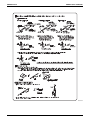
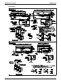
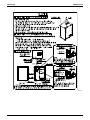
[Necessary Space]
When installing, secure the space mentioned below without fail.
(Refer to figure 2)
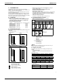
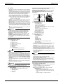
1. In case of a single installation [inch.]
2. In case of series installations [inch.]
3. Top view
4. Side view
5. Outside unit
6. Service Space (front side)
7. Service Space (back side)
8. Space for installing water piping
Secure an enough space for removing the front panel.
9. Ventilation Space
above the area (
) of the outside unit.
10. Secure spaces in the front, back and top sides as same as
the case of single installation.
DANGER
• Do not install unit in an area where flammable materials are
present due to risk of explosion resulting in serious injury or death.
• Refrigerant is heavier than air and replaces oxygen. A massive leak
could lead to oxygen depletion, especially in basements, and an asphyxiation hazard could occur leading to serious injury or death. Refer to the chapter “Caution for refrigerant leaks”.
NOTE
1. An inverter air conditioner may cause electronic noise generated
from AM broadcasting. Examine where to install the main air conditioner and electric wires, keeping proper distances away from
stereo equipment, personal computers, etc.
(Refer to figure 3)
1. Indoor unit
2. Branch switch, overcurrent breaker
3. Remote controller
4. Cool/Heat selector
5. Personal computer or radio
If the electric wave of AM broadcasting is particularly weak, keep distances of 10 ft or more and use conduit tubes for power supply and
transmission wiring.
2. Water quality
Water containing high level of foreign materials may cause the
corrosion of heat exchanger and piping or scale accumulation.
Use water satisfying “7-4 Water quality”.
3. Cooling tower
Use a closed type cooling tower without fail. (Open type tower
cannot be used.)
4. Strainer
Install a strainer (50 mesh or more) without fail at the inlet of water
piping. (If sands, wastes, rust particles, etc. are mixed in the water
circulation system, damage to the plate-type heat exchanger may
be caused by the corrosion of metal materials and clogging of the
heat exchanger.)
3P153897-12X
12
Installation of Outside Units
EDUS301214-N
Installation Manual
WARNING
NOTE
Do not install in the following locations.
• Locations such as kitchens which contain a lot of mineral oil or steam
in the atmosphere or where oil may splatter on the unit.
Resin parts may deteriorate, causing the unit to fall or leak.
• Locations where sulfurous acids and other corrosive gases may be
present in the atmosphere.
Copper piping and soldered joints may corrode, causing refrigerant
to leak.
• Locations where equipment that produces electromagnetic waves is
found.
The electromagnetic waves may cause the control system to malfunction, preventing normal operation.
4.
When handling the unit, take into account the following:
Fragile, handle the unit with care.
Keep the unit upright in order to avoid compressor damage.
2. Choose the path along which the unit is to be brought in ahead of
time.
3. In order to prevent any damage to the unit during installation, use
slings (cloth) or patch plates and lift the unit referring to figure 4.
4. Lift the unit preferably with a crane and 2 belts of at least 27 ft long.
5. When lifting the unit with a crane, always use protectors to prevent
belt damage and pay attention to the position of the unit’s center of
gravity.
6. Be sure use the standard supplied accessories and dedicated parts
as installation parts.
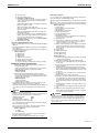
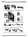
(Refer to figure 4)
1. Patch plates or clothes
2. Belt sling
NOTE
• Use belt sling of 13/16” width or less which adequately bears the
weight of the product.
5.
Resin clip plate
INSPECTING AND HANDLING THE UNIT
At delivery, the package should be checked and any damage should be
reported immediately to the carrier claims agent.
1.
• If the unit is to be installed on a roof, check the strength of the roof
and its drainage facilities first.
• Make sure the area around the machine drains properly by setting up
drainage grooves around the foundation.
(Condensate water is sometimes discharged from the outside unit
when it is running.)
• Use a nut with a resin clip plate to protect the nut tightening part from
rusting.
UNPACKING AND PLACING THE UNIT
13/16”
• Make sure the area around the machine drains properly by setting up
drainage grooves around the foundation.
• Make sure the unit is installed level on a sufficiently strong base to
prevent vibration and noise.
• Secure the unit to its base using foundation bolts. (Use four commercially available M12-type foundation bolts, nuts, and washers.)
• The foundation bolts should be inserted 13/16”.
• Fix 4 foundation bolts.
• Support the unit with the foundation which is
larger than the hatched area shown in figure 5.
(Refer to figure 5)
1. Front side
2. Position of foundation bolts
3. Hole for a foundation bolt
(I11/16” holes at 4 corners)
4. Avoid such a foundation where the unit is supported by
4 corner points.
NOTE
• When installing the unit closely contacting the wall for any
unavoidable reason, arrange so that no vibration from the unit may
be transmitted to the wall surface by insulating the vibration using
cushions, etc.
6.
WATER PIPING WORK
• The water pressure resistance of water piping of this outside unit is
285 psig.
• The connection port for water piping is located in the front. The connection ports for drain piping are located in the front and back. When
using the back port, change the cast iron plug from the back to the
front and securely close it.
• Because of indoor use, carry out piping work in such a way no water
may drop on the outer plate.
• The lateral protruding section of the drain piping should be short
(within 15-3/4) and installed in a downward direction.
The diameter of drain pipe should be the same as the diameter of
unit connection (1/2) or more.
• The diameter of water pipe should be the same as the diameter of
unit connection (1-1/4) or more.
• Install an air purge valve in the midway of the water piping to prevent
cavitation.
• After completing the drain piping work, make sure that the water runs
smoothly without any clogging by dust.
• Do not connect the drain outlet to the water outlet.
• Install a strainer (50 mesh or more) in the inlet of water piping within
a distance of 4.9 ft from the outside unit.
(If sand, waste or rust particles are mixed in the water circulation
system, metal materials will become corrosive.)
• Install insulation on the inlet/outlet of water piping to prevent condensation and freezing.
At installing insulation on water in/outlet pipe, use Polyurethane form
thickness 3/16 in. for insulation of water piping socket on heat
exchanger.
• Install insulation up to the base of heat exchanger as shown in the
figure 6.
• Install a gate valve for chemical cleaning in an easy position to handle.
• Use water pipes INCOMPLIANCE with the local and national codes.
• Run the water pump to flush inside of water piping.
Then, clean the strainer.
• If there is a possibility of freezing, take measures to prevent freezing.
• Tighten securely the connection of water piping and socket with
tightening torque of 220 ft·lbf or less.
(If a large torque is applied, the unit may be damaged.)
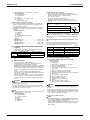
(Refer to figure 6)
1. Air purge
2. Outlet of water
3. Inlet of water
4. Gate valve
5. Water piping socket
6. Water piping
7. Insulation
8. Heat exchanger
9. Strainer
10. Drain valve
11. Connection port to draining piping
12. Insulation cover
13. 3-1/8 in. or less
14. Insulation of water piping socket
15. Drain piping
3P153897-12X
Installation of Outside Units
13
Installation Manual
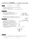
7.
HANDLING OF THE BRAZED PLATETYPE HEAT EXCHANGER
EDUS301214-N
7-3 Daily service and maintenance
1. Management of water quality
CAUTION
A brazed plate-type heat exchanger is used for this unit. Because
its structure is different from a conventional type heat exchanger, it
must be handled in a different manner.
7-1 When designing the equipment
1. Install a strainer (50 mesh or more) at the water inlet side adjacent to
2.
3.
4.
5.
6.
the outside unit in order to prevent any foreign materials such as
dust, sand, etc. from entering.
Depending on the water quality, scale may stick to the plate-type
heat exchanger. In order to remove scale, it is necessary to use
chemicals to clean it at regular intervals. To this end, install a gate
valve in the water piping. Set up a piping connection port on the piping between this gate valve and the outside unit for cleaning by
chemicals.
For the purpose of cleaning and water drain-off from the outside unit
(water draining during a long period of non-use in winter, draining
upon starting of season-off), install an “air discharge valve” and a
“water draining plug” at the inlet/outlet ports of water piping. In addition, install an “automatic air discharging valve” at the top of riser piping or at the top of a portion where air tends to stay.
Independent of the piping inlet of the outside unit, install a cleanable
strainer at a portion close to the pump piping inlet.
Carry out complete cooling/thermal insulation of water piping and
outdoor dehumidification. If complete cooling or thermal insulation
has not been carried out, any damage may be caused during severe
winter due to freezing, in addition to thermal loss.
When you stop operation during night or winter, it is necessary to take
measures to prevent water-related circuits from natural freezing in the
area the ambient temperature drops below 32°F (by water drain off,
keeping the circulation pump running, warming up by a heater, etc.)
Freezing of water related circuits may result in any damage to the
plate-type heat exchanger. Therefore, take appropriate measures
depending on the circumstances of use.
(Refer to figure 7)
1. Example of piping
2. Water inlet piping
3. Strainer
4. Air discharge valve (for joint use with cleaning port)
5. Cleaning device
6. Strainer for pump
7. Automatic air discharge valve
8. Water outlet piping
9. Joint use with water draining plug
10. Plate-type heat exchanger
11. Outside unit
7-2 Before starting a test run
1. Before starting a test run, please make sure that the piping work has
2.
3.
4.
been carried out in a proper manner. Especially, make sure that the
strainer, air discharge valve, automatic water supply valve, expansion
tank and cistern are positioned at their places correctly.
After water has been completely filled in, first run the pump only, and
then make sure that no air has been caught in the water circulation
system and that the water flow rate is correct. If any air has been
caught or the flow rate is not enough, the plate-type heat exchanger
may freeze. Measure any water pressure loss before and after the
outside unit and make sure that the flow rate is as designed. In case
of any abnormality, stop the test run immediately and carry out trouble shooting to resolve the trouble.
Following the installation manual, carry out a test run of the outside
unit.
After the test run has been completed, inspect the strainer at the inlet
piping of the outside unit. Clean it if it is dirty.
2.
3.
The plate-type heat exchanger has a structure that does not permit
dismantling and cleaning, or replacing any parts. Please pay attention
carefully to the quality of water to be used for the plate-type heat
exchanger in order to prevent corrosion and sticking of scale.
The water to be used for the plate-type heat exchanger should have at
least the quality as specified in the table below.
When using any corrosion prevention agent, scale depressant agent,
etc., such agent should have no corrosive features against stainless
steel and copper.
Management of condenser water flow rate
If the condenser water flow rate is not enough, it will result in freezing
damage to the plate-type heat exchanger. Check for any clogging of
the strainer, any air being caught, any reduction in the flow rate due
to failure of the circulation pump by measuring the temperature and
pressure differences at the inlet and outlet ports of the plate-type
heat exchanger. If the aged difference in the temperature or pressure
has increased beyond the proper range, the flow rate should have
decreased. Stop the operation and remove the cause before restarting the operation.
Steps to be taken if a freeze-protection device is activated
If the freeze-protection device is activated during operation, be sure
to remove the cause before restarting the operation. If the freezeprotection device has been once activated, a partial freezing has
already occurred. If you restart the operation without removing the
cause, the plate-type heat exchanger will be closed and the ice cannot be melted, and in addition, the freezing process will be repeated,
resulting in any damage to the plate-type heat exchanger, and this
can lead to refrigerant leaking or water entering the refrigerant circuit.
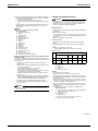
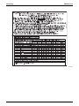
7-4 Water quality
Water quality standards for condenser water, hot water and
makeup water (4) (6)
Cooling water system (3)
Circulation system
Item (5)
Circulation
water
Makeup
water
Hot water system (2)
Circulation
water
(68°F ~ 140°F)
Makeup
water
Tendency (1)
Corrosion
Scale
6.5 to 8.2 6.0 to 8.0 7.0 to 8.0 7.0 to 8.0
{
{
Electrical Conductivity Less than Less than Less than Less than
(mS/ft)(77°F)
24.4
9.1
9.1
9.1
{
{
Chloride ions
–
(mgcl /L)
Less than Less than Less than Less than
200
50
50
50
{
Sulfate ions
2(mgSO4 /L)
Less than Less than Less than Less than
200
50
50
50
{
Acid consumption
(pH4.8) (mgCaCO3/L)
Less than Less than Less than Less than
100
50
50
50
{
Total hardness
(mgCaCO3/L)
Less than Less than Less than Less than
200
70
70
70
{
Calcium hardness
(mgCaCO3/L)
Less than Less than Less than Less than
150
50
50
50
{
Ionic-state silica
(mgSiO2/L)
Less than Less than Less than Less than
50
30
30
30
{
Standard items
pH (77°F)
Reference items
Iron (mgFe/L)
Less than Less than Less than Less than
1.0
0.3
1.0
0.3
{
Copper (mgCu/L)
Less than Less than Less than Less than
0.3
0.1
1.0
0.1
{
Sulfate ion
2(mgS /L)
Shall not be Shall not be Shall not be Shall not be
detected
detected
detected
detected
{
Ammonium ion
+
(mgNH4 /L)
Less than Less than Less than Less than
1.0
0.1
0.3
0.1
{
Residual chlorine
(mgCl/L)
Less than Less than Less than Less than
0.3
0.3
0.25
0.3
{
Free carbon dioxide Less than Less than Less than Less than
(mgCO2/L)
4.0
4.0
0.4
4.0
{
Stability index
{
6.0 to 7.0
—
—
—
{
{
3P153897-12X
14
Installation of Outside Units
EDUS301214-N
[NOTES]
(1) The circle marks in the columns for corrosion or scale to develop.
(2) Corrosion has a tendency to occur when water temperature is high
(104°F or more), and if metals with no protective coating whatSOever
are directly exposed to water, it would be a good idea to take effective measures against corrosion such as adding a corrosion inhibitor
or deterioration treatment.
(3) In a condenser water circuit that uses a closed cooling tower, the
closed circuit circulating water and makeup water must satisfy its
water quality standards for the hot water system, and passing water
and makeup water must satisfy those for the circulation type cooling
water system.
(4) The supply water must be clean tap water, industrial water or clean
underground water.
Do not use purified or softened water.
(5) The fifteen items in the table above represent typical causes of corrosion and scale.
(6) Once-through water may cause corrosion.
Do not use once-through water.
7-5 Maintenance of plate-type heat exchanger
The performance of a plate-type heat exchanger may decline due to
scale accumulation. It may be damaged by freezing due to the drop of
flow rate. For this reason, it is necessary to carry out programmed maintenances at a regular interval in order to prevent the scale from being
generated.
1. Before entering the season for use, carry out the following
inspections:
2.
3.
1) Conduct a water quality test and make sure that it is within the
standard.
2) Clean the strainer.
3) Make sure that the flow rate is correct.
4) Make sure that the operational conditions (pressure, flow rate,
outlet temperature, etc.) are normal.
Because the plate-type heat exchanger has a structure which does
not permit disassembling and cleaning, follow the following procedures for cleaning:
1) For maintenance purposes it is required to provide for a connection port on the water inlet and on the water outlet. You must connect a circulation pump in between these 2 connection ports when
cleaning the plate-type heat exchanger with chemicals.
For cleaning the scale in the plate-type heat exchanger it is recommended to use a solution with 5% diluted formic, citric, oxalic,
acetic or phosphoric acid.
Never use hydrochloric, sulfuric or nitric acid because such solutions have a strong corrosive feature.
2) Make sure to provide for a stop valve in front of that inlet water
pipe connection port and for a stop valve after the outlet water
pipe connection port.
3) Connect the piping for circulation of cleaning chemicals to the
inlet and outlet piping of plate-type heat exchanger. Fill the cleaning solution of 122 - 144°F for a while in the plate-type heat
exchanger. Then, circulate the cleaning solution by a pump for 25 hours.
The time for cleaning depends on the temperature of cleaning
solution or the degree of scale accumulation. Therefore, please
watch the change of the dirtiness (color) of cleaning solution to
determine the level of removal of scale.
4) After circulating the cleaning solution, discharge the solution from
the plate-type heat exchanger, fill the heat exchanger with a solution of 1-2% sodium hydroxide (NaOH) or sodium bicarbonate
(NaHCO3). Circulate this solution for 15-20 minutes for neutralization purpose.
5) After the process of neutralization has been completed, rinse the
inner part of the plate-type heat exchanger with care using fresh
and clean water.
6) When using any cleaning agent sold in the market, check in
advance that such agent has no corrosive features against stainless steel and copper.
7) For details of cleaning method, ask the manufacturer of related
cleaning agent.
After cleaning has been completed, make sure that the unit can be
operated in a normal fashion.
Installation Manual
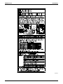
8.
FIELD WIRING
NOTE
• All field wiring and components must be installed by a licensed electrician and must comply with relevant local and national regulations.
• The field wiring must be carried out in accordance with the wiring
diagrams and the instructions given below.
• Be sure to use a dedicated power supply circuit. Never use a power
supply shared by another appliance.
• Do not operate until refrigerant piping work is completed.
(If operated before complete the piping work, the compressor may
be broken down.)
• Never remove thermistor, sensor or etc. when connecting power
supply and transmission wiring.
(If operated with thermistor, sensor or etc. removed, the compressor
may be broken down.)
• Be sure to install a ground fault circuit interrupter.
(This unit uses an inverter, so install a ground fault circuit interrupter
that is capable of handling high harmonics in order to prevent malfunctioning of a ground fault circuit interrupter itself.)
• This product have reversed phase protection detector only works
when the product started up.
• Replace two of the three phases (L1, L2, and L3) during reversephase protection circuit operation.
Reversed phase detection is not performed while the product is
operating.
• Do not run the unit by short cutting the protection device (S1PH).
If there exists the possibility of reversed phase, lose phase, momentary blackout or the power supply goes on and off while the product
is operating, attach a reversed phase protection circuit locally. Running the product in reversed phase may break the compressor and
other parts.
• Attach the power supply wiring securely.
8-1 Optional parts
Cool/Heat selector
S1S .............................. Selector switch (fan, cool/heat)
S2S .............................. Selector switch (cool/heat)
NOTE
• Use copper conductors only.
• When using the adaptor for sequential start, refer to chapter “Examples”.
• For transmission wiring to outside-outside transmission F1-F2,
outside-indoor transmission F1-F2, refer to chapter “Examples”.
• For transmission wiring to the central remote controller, refer to the
installation manual of the central remote controller.
• Use insulated wire for the power supply.
8-2 Power supply circuit and wire requirements
A power supply circuit (see table below) must be provided for connection of the unit. This circuit must be protected with the required safety
devices, i.e. a main switch, a slow blow fuse on each phase and a
ground fault circuit interrupter.
Phase and
frequency
Voltage
Minimum
circuit amp.
Recommended
fuses
Transmission
wiring
selection
I3, 60 Hz
460 V
10.2 A
15 A
AWG18-16
RWEYQ144/168PYDN I3, 60 Hz
460 V
10.2+10.2 A
15+15 A
AWG18-16
RWEYQ216/252PYDN I3, 60 Hz
460 V
10.2+10.2+10.2 A
15+15+15 A
AWG18-16
22.4 A
40 A
AWG18-16
22.4+22.4 A
40+40 A
AWG18-16
40+40+40 A
AWG18-16
RWEYQ72/84PYDN
RWEYQ72/84PTJU
I3, 60 Hz 208/230 V
RWEYQ144/168PTJU I3, 60 Hz 208/230 V
RWEYQ216/252PTJU I3, 60 Hz 208/230 V 22.4+22.4+22.4 A
NOTE
• Select the power supply wire in accordance with relevant local and
national regulations.
• Wire size must comply with the applicable local and national code.
• Specifications for local power supply and branch wiring are in compliance with local coDE
3P153897-12X
Installation of Outside Units
15
Installation Manual
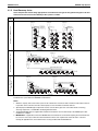
8-3 General
• Make sure to connect the power supply wire to the power supply terminal block and to clamp it as shown in figure 8, chapter “Field wiring
connection”.
• As this unit is equipped with an inverter, installing a phase advancing
capacitor will not only reduce the power factor improvement effect,
but also may cause the capacitor to overheat due to high-frequency
waves. Therefore, never install a phase advancing capacitor.
• Keep power supply imbalance within 2% of the supply rating.
1. Large imbalance will shorten the life of the smoothing capacitor.
2. As a protective measure, the product will stop operating and an
error indication will be made, when power supply imbalance
exceeds 4% of the supply rating.
• Follow the “electrical wiring diagram” when carrying out any electrical wiring.
• Only proceed with wiring work after blocking off all power supply.
• Always ground wires. (In accordance with national regulations of the
pertinent country.)
• This unit uses an inverter, and therefore generates noise, which will
have to be reduced to avoid interfering with other devices. The outer
casing of the product may take on an electrical charge due to leaked
electrical current, which will have to be discharged with the grounding.
• This unit has a negative phase protection circuit. (If it operates, only
operate the unit after correcting the wiring.)
WARNING
• Do not ground units to gas pipes, sewage pipes, lightning rods, or
telephone ground wires because incomplete grounding could
cause a severe shock hazard resulting in severe injury or death.
Gas pipes: can explode or catch fire if there is a gas leak.
Sewage pipes: no grounding effect is possible if hard plastic piping is used.
Telephone ground wires and lightning rods: dangerous when
struck by lightning due to an abnormal rise in electrical potential in
the grounding.
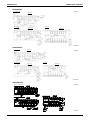
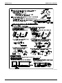
8-4 Examples
System example (Refer to figure 8)
1. Field power supply
2. Main switch
3. Disconnect switch
4. Fuse
5. Ground fault circuit interrupter
6. Remote controller
7. Outside unit
8. BRANCHSELECTOR unit
9. Indoor unit
10. Cool/Heat selector
power supply wiring (sheathed wire)
transmission wiring (sheathed wire)
CAUTION
• Use a conduit for the power supply wiring.
• Outside the unit, make sure the low-voltage electric wiring (i.e. for the
remote controller, transmission, etc.) and the high-voltage electric wiring do not pass near each other, keeping them at least 5 in. apart. Proximity may cause electrical interference, malfunctions, and breakage.
• Be sure to connect the power supply wiring to the power supply terminal block and secure it as described in Field wiring connection.
• Transmission wiring should be secured as described in Field wiring
connection.
• Secure the wiring with the accessory clamps so that it does not touch
the piping.
• Make sure the wiring and the control box cover do not stick up above
the structure, and close the cover firmly.
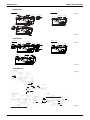
EDUS301214-N
Connect the wire to the terminal block on PC board with care since too
much pressure may cause breakage of the PC board.
Field wiring connection: transmission wiring, interlock circuit, pump
operation output and Cool/Heat selector
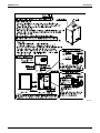
Power supply and transmission wiring: Connect it using conduit
mounting plates.
Conduit
(field supply)
Top plate
Top plate
Conduit
mounting
plate
(accessory)
Lock nut
(field supply)
[In case of single outside unit]
(Refer to figure 10)
1. Cool/Heat selector
2. Outside unit PC board (A1P)
3. Take care of the polarity
4. Use the conductor of sheathed wire (2 wire) (no polarity)
5. Terminal board (field supply)
6. Indoor unit
7. Never connect the power supply wire.
8. BRANCHSELECTOR unit A
9. BRANCHSELECTOR unit B
10. Last BRANCHSELECTOR unit
11. Cool-only unit
12. ABC I/P PC board (A5P)
[In case of multiple outside units]
(Refer to figure 11)
1. Unit A (Master unit)
2. Unit B
3. Unit C
4. TO IN/D UNIT
5. TO OUT/D UNIT
6. TO MULTI UNIT
7. To Cool/Heat selector (only Heat pump system)
8. To indoor unit
9. To other systems
• The transmission wiring between the outside units in the same pipe
line must be connected to the Q1/Q2 (Out Multi) terminals.
Connecting the wires to the (Out-Out) terminals results in system
malfunction.
• The wiring for the other pipe line must be connected to the F1/F2
(Out-Out) terminals of the PC board in the outside unit to which the
transmission wiring for the indoor units is connected.
• The outside unit to which the transmission wiring for the indoor units
is connected is master unit.
• The transmission wiring between the outside units must be 100 ft. in
length at maximum.
NOTE
• Be sure to keep the power supply and transmission wiring apart from
each other.
Be careful about polarity of the transmission wiring.
Make sure that the transmission wiring is clamped as shown in the
figure in chapter “Field wiring connection”.
Check that wiring does not make contact with refrigerant piping.
Firmly close the lid and arrange the electric wires so as to prevent
the lid or other parts from coming loose.
[Setting the interlock circuit and pump operation output.]
WARNING
• Never connect power supply wiring to the terminal block for remote
controller wiring as this could damage the entire system.
Picking power supply and transmission wiring
(Refer to figure 9)
1. Power supply wiring and wiring for pump operation
(High voltage)
2. Transmission wiring
(Low voltage)
3. Set apart
¢Pump operation output [high voltage]²
• Use insulated wires of the size as mentioned below having rated voltage of 250 V or more:
For single core: AWG16 or larger (conduit pipe work)
For multiple cores: AWG18 or larger
*The wiring for pump operation output is to be procured locally.
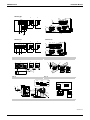
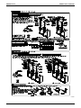
(Refer to figure 12)
1. Pump operation output terminal (X2M).
When water pump is linked with system operation, water
pump operation circuit shall be set between terminals (1)
and (2).
Contact specification --- 220 VAC, 3 mA-0.5 A
3P153897-12X
16
Installation of Outside Units
EDUS301214-N
2. PC board (A1P)
3. Mount an insulation sleeve.
4. Connection of interlock circuit
Do not forget to connect an interlock circuit (an auxiliary acontact of electromagnetic switch for the water pump) to
each outside unit.
(Select without fail an auxiliary a-contact able to switch minimum load of DC15 V, 1 mA.)
¢When connecting for each outside unit²
Connect to the terminal block (X3M) as shown in the bottom
right of the sketch.
¢When connecting multiple outside units as 1 single unit
(centralized interlock)²
For this unit, it is possible to make a centralized interlock of
multiple outside units using an adapter (sold separately as
an accessory) for external control of outside units.
For details of wiring connection, refer to “How to centralized interlock wiring”.
5. ABC I/P PC board (A5P)
¢How to the centralized interlock wiring²
• When centralized interlock is done, see “8-5 In case of a local setting” -(3).
• No wiring to terminal block X3M is necessary when centralized interlock is employed.
• For multiple outside units, external/external transmission wiring shall
be done for master unit only.
(Refer to figure 13)
1. Outside unit A
2. Outside unit B
3. Outside unit C
4. Adapter for external control
5. Interlock circuit of water pump
6. Out-Out transmission wiring
7. Use the conductor of sheathed wire (2 wire) (no polarity)
[Setting the cool/heat operation type]
1. Performing cool/heat setting with the remote controller connected to the indoor unit.
Keep the Cool/Heat selector switch (DS1) on the outside unit
PC board (A1P) at the factory setting position OFF.
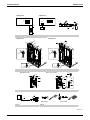
(Refer to figure 16)
1. Remote controller
2. Performing cool/heat setting with the Cool/Heat selector.
Connect the Cool/Heat selector (optional) to the A/B/C terminals and set the Cool/Heat selector switch (DS1) on the outside
unit PC board (A1P) to ON.
(Refer to figure 17)
1. Cool/Heat selector
2. ABC I/P PC board (A5P)
• The wiring from the indoor units must be connected to the F1/F2
(In-Out) terminals on the PC board in the outside unit.
• For the above wiring, always use sheathed vinyl wire with AWG18-16
(2 core wire). (3 core wire is allowable for the Cool/Heat selector
only.)
NOTE
• All transmission wire is field supply.
• Be sure to follow the limits below. If the transmission wiring is beyond
these limits, it may result in malfunction of transmission.
Maximum wiring length:
3280 ft.
Total wiring length:
6560 ft.
Max. branches No. of branches: 16
Wire length between outside units: 98 ft.
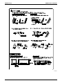
Installation Manual
Field wiring connection:
L1, L2, L3, phase of the power supply wiring should be clamped to the
safety catch using the included clamp material.
The green and yellow striped wrapped wires should be used for grounding.
Make sure to connect the power supply wire to the power supply terminal block and fix it using attached clamp as shown in figure 15 and 19.
(Refer to figure 15)
1. Power supply
2. Branch switch, overcurrent breaker
3. Grounding wire
4. Ground fault circuit interrupter
5. Attach insulation sleeves.
6. Power supply terminal block
7. Grounding terminal
8. Retain the ground wires along with the power supply wires
using the accessory clamp (A).
9. Grounding wire
10. When wiring, do not allow the ground wires to contact the
compressor lead wires. If the wires contact each other,
adverse effects may occur to other units.
11. When connecting two wires to one terminal, ensure that the
crimp-style terminals face with each other back to back.
Moreover, make sure that the wire of the smaller gauge is
located above.
12. Terminal block
13. Crimp-style terminal
14. Wire gauge: Small
15. Wire gauge: Large
(Refer to figure 19)
1. Intake for power supply wiring, pump operation output (high
voltage) and ground wiring.
2. Stop valve for discharge gas (high temperature part)
3. Insert the accessory clamp (B) in the hole of the fixing plate
for stop valve.
4. Power supply wiring, pump operation output (high voltage)
and ground wiring.
5. Retain the power supply wiring, pump operation output
(high voltage) and ground wiring with the accessory clamp
(B) to prevent them from touching with the stop valve for discharge gas.
6. Insert the accessory clamp (B) in the hole of the bottom of
electrical box.
7. Intake for transmission wiring. (low voltage)
8. Make sure to provide for a downward loop in the transmission wiring right in front of the location where the wiring is to
be fixed over the top plate of the control box. This in order to
prevent that condensate drips off the wiring into the control
box.
9. Fix the transmission wiring to resin clamps with the accessory clamps (A)
10. Pass the transmission wiring (low voltage) through the wire
clip.
11. Retain the power supply wiring, pump operation output
(high voltage) and ground wiring to the bottom of electrical
box with the accessory clamp (B)
WARNING
• Use only specified wire and connect wires to terminals tightly. Be
careful that wires do not place external stress on terminals. Keep
wires in neat order so as not to obstruct other equipment. Incomplete connections could result in overheating, and in worse cases,
electric shock or fire.
Up to 16 branches are possible for transmission wiring. No branching is allowed after branching.
Never connect the power supply to transmission wiring terminal
block. Otherwise the entire system may break down.
(Refer to figure 14)
1. Branch
2. Subbranching
For low-noise operation, it is necessary to get the optional “External control adaptor for outside unit”.
For details, see the installation manual attached to the adaptor.
3P153897-12X
Installation of Outside Units
17
Installation Manual
EDUS301214-N
9.
CAUTION
CAUTION
¢Precautions when laying power supply wiring²
Use round pressure terminals for connections to the power supply
terminal block.
Round pressure
Power supply wire
terminal
After completing installation, be sure to open the valves.
(See 9-9 Additional refrigerant charge for details) (Operating the
unit with the valves shut will break the compressor.)
Use R410A to add refrigerant. (The R410A refrigerant cylinder has
a pink stripe painted around it.)
All field piping must be installed by a licensed refrigeration technician and must comply with relevant local and national regulations.
CAUTION TO BE TAKEN WHEN BRAZING REFRIGERANT PIPING
Do not use flux when brazing copper-to copper refrigerant piping.
(Particularly for the HFC refrigerant piping) Therefore, use the
phosphor copper brazing filler metal (B-Cu93P-710/795: ISO
3677) which does not require flux.
Note: Flux has an extremely negative effect on refrigerant piping
systems. For instance, if the chlorine based flux is used, it
will cause pipe corrosion or, in particular, if the flux contains
fluorine, it will damage the refrigerant oil.
When none is available, follow the instructions below.
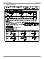
• Do not connect wiring of different thicknesses to the power supply
terminal block. (Slack in the power supply wiring may cause
abnormal heat.)
• When connecting wiring which is the same thickness, do as
shown in the figure below.
Connect samethickness wiring
to both sides.
It is forbidden to
connect two to
one side.
REFRIGERANT PIPING
It is forbidden to
connect wiring of
different thicknesses.
NOTE
• Installation tools:
•
•
•
•
Gauge manifold, charge hose, etc.
Make sure to use installation tools that are exclusively used for
R410A installations to withstand the pressure and to prevent foreign materials (e.g. mineral oils such as SUNISO and moisture)
from mixing into the system.
(The screw specifications differ for R410A and R407C.)
Vacuum pump
1. Use a 2-stage vacuum pump with a non-return valve.
2. Make sure the pump oil does not flow oppositely into the system
while the pump is not working.
3. Use a vacuum pump which can evacuate to 500 microns.
For wiring, use the designated power supply wire and connect
firmly, then secure to prevent outside pressure being exerted on
the terminal board.
Use an appropriate screwdriver for tightening the terminal
screws. A screwdriver with a small head will strip the head and
make proper tightening impossible.
Over-tightening the terminal screws may break them.
See the table below for tightening torque for the terminal screws.
Tightening torque
(ft · lbf)
M5 (Power supply terminal block)
M5 (Ground)
M3 (Transmission wiring terminal block)
2.21-3.02
9-1 Selection of piping material
0.59-0.72
1. Foreign materials inside pipes (including oils for fabrication) must be
¢Precautions when connecting the ground²
When pulling the ground wire out, wire it so that it comes through the
cut out section of the cup washer. (An improper ground connection
may prevent a good ground from being achieved.)
9 mg/10 ft or less.
2. Use the following material specification for refrigerant piping:
•
Cup washer
Round pressure terminal
3.
Cut out section
8-5 In case of a local setting
If necessary, do the local settings as mentioned in the table below. For
setting, refer to the plate “Cares to be taken in servicing” attached to the
cover of control box.
Typical local settings
For other settings than mentioned in the table below, refer to the
equipment design materials and service manual.
This setting is done when switching between cooling and
heating is performed by a switching remote controller (sold
separately as an accessory) installed on the outside unit.
(2) Setting to prohibit sequenced This setting is done when the outside units are not started in
start
a sequenced order.
(3) Setting of centralized interlock These settings are done when the interlocks are connected
in a lump-sum manner or when performing a demand operaSetting of external demand
tion by external instruction.
This
setting is done when making an abnormal display (HJ)
(4) Setting of abnormal display
a remote controller when the interlock contact is OFF
when interlock contact is OFF on
(when the heat source water pump is not operated).
4.
5.
6.
(1) Setting of switching between
cooling and heating
CAUTION
A separate adapter (sold separately as an accessory) for external
control of an outside unit is necessary when doing a demand operation from an external instruction, setting of cooling and heating
through a centralized remote controller for cooling and heating
(sold separately as an accessory) and setting of centralized interlock. For details, refer to the manual attached to the adapter.
Construction material: Phosphoric acid deoxidized seamless
copper for refrigerant.
Size: Determine the proper size referring to chapter “Example of
connection”.
• The wall thickness of the refrigerant piping should comply with
relevant local and national regulations. For R410A the design
pressure is 450 psig.
Make sure to use the particular branches of piping that have been
selected referring to chapter “Example of connection”.
Refer to chapter “Stop valve operation procedure” in 9-10 about the
stop valve operation procedure.
Make sure to perform the piping installation within the range of the
maximum allowable pipe length, allowable level difference and allowable length after branching as indicated in chapter “Example of connection”
For installation of the refrigerant branching kit, refer to the installation
manual delivered with the kit.
And follow the conditions listed below.
• Mount the REFNET joint so that it branches either horizontally or
vertically.
• Mount the REFNET header so that it branches horizontally.
(Refer to figure 22)
1. Horizontal connections
2. Up to ± ° or vertically
3. Horizontal connections
To connect the piping between outside units, an optional piping kit
(multi connection piping kit) is always required. When installing the
piping, follow the instructions in the installation manual that comes
with the kit.
•
7.
Restriction for the installation of the outside unit multi connection
piping kit
• Install the joint horizontally within a lean of ±15° with caution nameplate on top. Refer to figure 23 (Fig. A)
Do not connect it vertically. Refer to figure 23 (Fig. B)
• Reserve the straight part of 19-11/16 in. or more to the branch pipe
and do not bend the local pipe in that area. Straight part of 19-11/16
in. or more can be reserved if a local pipe (straight pipe) of 4-3/4 in.
or more is connected to the joint. Refer to figure 23 (Fig. C)
3P153897-12X
18
Installation of Outside Units
EDUS301214-N
• Incorrect installation may cause breakage of outside unit.
(Refer to figure 23)
1. Caution nameplate
2. Horizontal line
3. Ground
4. Straight part of 19-11/16 in. or more
5. Local pipe
(4-3/4 in. length or more)
Precautions when selecting branch piping.
• If the overall equivalent length of piping between the outside units
and indoor units is 262.5 ft or more, be sure to enlarge the main pipe
in the liquid-side branch piping.
Depending on the length of the refrigerant piping, the cooling/heating capacity may drop, but even in such cases it is ok to enlarge the
main pipe.
(Refer to figure 21)
1. Outside unit
2. Main pipe
3. Enlarge
4. The first refrigerant branching kit.
5. Indoor unit
[Liquid side]
RWEYQ72/84P type: I3/8”o I1/2”
RWEYQ144P type: I1/2”o I5/8”
RWEYQ168/216P type: I5/8”o I3/4”
RWEYQ252P type: I3/4”o I7/8”
9-2 Protection against contamination when installing pipes
Installation Manual
Precautions when connecting pipes
• See the following table for flare part machining dimensions.
• When connecting the flare nuts, apply refrigerant oil to the inside of
the flares and turn them three or four times at first.
(Use ester oil or ether oil.)
• See the following table for tightening torque.
(Applying too much torque may cause the flares to crack.)
• After all the piping has been connected, check the gas leak with
nitrogen.
pipe size
(in.)
tightening torque
(ft. · lbf)
A
(in.)
I 3/8”
24.1 - 29.4
0.504 - 0.520
I 1/2”
36.5 - 44.5
0.638 - 0.654
I 5/8”
45.6 - 55.6
0.760 - 0.776
flare shape
90˚±2
45
A
˚±2
R=0.016~0.031
Not recommendable but in case of emergency
You must use a torque wrench but if you are obliged to install the unit
without a torque wrench, you may follow the installation method mentioned below.
After the work is finished, make sure to check that there is no gas
leak.
When you keep on tightening the flare nut with a spanner, there is a
point where the tightening torque suddenly increases. From that position, further tighten the flare nut the angle shown below:
(Unit: in.)
Pipe size
Further tightening angle
I 3/8”
60 to 90 degrees
Approx. 7-7/8
I 1/2”
30 to 60 degrees
Approx. 9-13/16
Place
I 5/8”
30 to 60 degrees
Approx. 11-13/16
Outdoor
I 3/4”
20 to 35 degrees
Approx. 17-3/4
•
Take measures to prevent foreign materials like moisture and
contamination from mixing into the system.
Installation period
Protection method
More than a month
Pinch the pipe
Less than a month
Pinch or tape the pipe
Indoor
Regardless of the period
• Great caution is needed when passing copper tubes through
walls.
9-3 Pipe connection
•
•
•
Only use the flare nuts included with the unit.
Using different flare nuts may cause the refrigerant to leak.
Be sure to perform a nitrogen blow when brazing.
(Brazing without performing nitrogen replacement or releasing
nitrogen into the piping will create large quantities of oxidized film
on the inside of the pipes, adversely affecting valves and compressors in the refrigerating system and preventing normal operation.)
Do not use a flux when brazing the refrigerant pipe joints.
Use phosphor copper brazing (B-Cu93P-710/795: ISO 3677)
which does not require flux.
(Flux has an extremely negative effect on refrigerant piping systems. For instance, if chlorine based flux is used, it will cause pipe
corrosion. If the flux contains fluorine, it will damage the refrigerant oil.)
DANGER
• Use of oxygen could cause an explosion resulting in severe injury
or death. Only use nitrogen gas.
• Refrigerant gas may produce toxic gas if it comes in contact with fire
such as from a fan heater, stove or cooking device. Exposure to this
gas could cause severe injury or death.
NOTE
• The pressure regulator for the nitrogen released when doing the
brazing should be set to 2.9 psig or less.
(Refer to figure 18)
1. Refrigerant piping
2. Location to be brazed
3. Nitrogen
4. Taping
5. Manual valve
6. Regulator
Recommended arm length of tool
9-4 Connecting the refrigerant piping
Connect piping to outside unit by using accessory pipes
(Refer to figure 20)
1. Gas side piping
2. (field supply)
3. Gas side accessory pipe (for suction gas (1))
4. Liquid side pipe (field supply)
5. Flare nut (Included in the unit)
6. Accessory pipes (for discharge gas and suction gas (2))
is not used.
7. Piping on discharge gas side (field supply)
8. Piping on suction gas side (field supply)
9. Cut off the hatched area and use it as a cover for the drilled.
10. Hatched area
11. Accessory pipe (for discharge gas)
12. Accessory pipe (for suction gas)
13. Guideline for pipe machining
14. Accessory pipe (for suction gas (2))
15. Brazing
16. Accessory pipe (for suction gas (1))
17. Before fitting to the product, apply brazing.
NOTE
• Be sure to use the attached pipe when carrying out piping work in
the field.
• Be sure that the local piping does not touch other pipes, the bottom
panel or side panel. Especially for the bottom and side connection, be
sure to protect the local piping with the provided insulation, to prevent
it from coming into contact with the casing.
Precautions for installation of units
NOTE
• The outside unit multi connection piping kit that is sold separately as
an option (BHFP22MA56U + 84U, BHFP26MA56U + 84U) is necessary for the multi installation of outside units.
• See the installation manual attached to the kit with attention to installation restrictions described in “connecting the refrigerant piping”
when installing.
3P153897-12X
Installation of Outside Units
19
Installation Manual
EDUS301214-N
¢Cautions for installation of multiple outside units²
1. The piping between the outside units must be routed level or slightly
upward to avoid the risk of oil detention to the piping side.
Pattern 1
Piping between outside units
to indoor
unit
Pattern 2
to indoor
unit
Change to pattern 1 or pattern 2
Prohibited pattern
Downward
inclination
to indoor
unit
Oil remains in piping
Downward
inclination
2. The gas piping (both discharge and suction gas piping in case of the
heat recovery system) after branched, install without fail a trap of 8
in. or more using the piping included in the piping kit for connecting
the outside unit. Otherwise, the refrigerant may stay within the piping, causing any damage to the outside unit.
8 in. or more
Prohibited pattern
No trap has been installed in the gas piping.
to indoor unit
★Oil may remain in the farthest outside unit.
Change to pattern 1 or pattern 2
3. If the piping length between the outside unit connecting pipe kit or
between the outside units exceeds 80 in., create a rise of 8 in. or
more in the gas piping within a length of 80 in. from the kit.
If 80 in. or less Piping between outside unit
80 in. or less
to indoor
unit
If 80 in. or more
to indoor
unit
80 in. or less
Rising height:
8 in. or more
3P153897-12X
20
Installation of Outside Units
Liquid piping
Gas piping
Suction gas piping
Liquid piping
Installation of Outside Units
Between outside and indoor units
Between indoor and indoor units
Between outside and outside units
Between outside branch and outside unit
(In case of RWEYQ144 or more)
Between outside (∗)
and indoor units
Actual pipe length
Difference in height
Difference in height
Difference in height
Actual pipe length
Total extension length
Equivalent length
Actual pipe length
When multiple
outside units
installed
(RWEYQ144~)
Single outside
unit installed
(RWEYQ72, 84)
NOTE:
If a negative result is gotten for R from the formula at right,
no refrigerant needs to be added.
Additional refrigerant to be charged R (lbs)
(R should be rounded off in units of 0.1 lbs.)
How to calculate the additional refrigerant
to be charged
A
B1
g
f
h
F
1
i
G
j
2
b
B1
F
branch
First outside h
g
f
A
1
i
2
k
H3
C
4
5
e
6
B4
q
p
D
c
B2
3 4
m
l
B
o
n
C
r
d
5
B3
e
6
B4
q
p
D
E
r
7 H2
8
s
Cooling only
( 7 · 8 )
H1
8
s
Cooling only
( 7 · 8 )
H1
7 H2
REFNET joint (A-G)
E
REFNET joint (A-G)
d
Heat recovery system
( 1 - 6 )
3
c
l B2 n B3
m
o
Outside unit
j
G
b
k
B
BS units Indoor units Heat recovery
( B1 - B4 ) ( 1 - 8 ) system ( 1 - 6 )
a
Outside unit
BS units Indoor units
( B1 - B4 ) ( 1 - 8 )
a
Branch with REFNET joint
Example 5
d
1
B1
f
e
2
B2
h
g
a
r
u
d
c
1
B1
s
f
e
2
B2
h
g
A
i
H3
Outside unit
6
o
7
B
o
7
p
H1
8 H2
REFNET header
REFNET joint (A·B)
6
l
5
l
B
B5 n
p
8
Cooling only
( 5 · 6 )
H2
Cooling only
( 5 · 6 )
Heat recovery system
( 1 - 4 , 7 · 8 )
Indoor units
( 1 - 8 )
BS units
( B1 - B5 )
Heat recovery system
( 1 - 4 , 7 · 8 )
k
t
5
j
i
B5 n
4
B4
4
j
b
B4
m
k
3
b
m
REFNET joint (A·B)
3
B3
A
B3
Indoor units
BS units ( B1 - B5 ) ( 1 - 8 )
H1
Outside unit
c
REFNET header
a
Branch with REFNET joint and REFNET header
Example 2
Example 6
Example 3
1
B1
e
2
B2
a
d
g
f
a
c
b
1
B1
e
d
2
B2
3
4
f B3 h B4
g
i
Outside unit
BS units Indoor units
( B1 - B6 ) ( 1 - 8 )
c
b
B5
5
4
B4
5
B5
k
j
6
m
l
n
k
j
H3
6
m
l
7 H2
n
H1
8
o
REFNET header
B6
8
Cooling only
( 7 · 8 )
Heat recovery
system ( 1 - 6 )
Indoor units
( 1 - 8 )
BS units
( B1 - B6 )
Cooling only
( 7 · 8 )
o
REFNET header
B6
7 H2
H1
Heat recovery system
( 1 - 6 )
i
h
Outside
unit
3
B3
Branch with REFNET header
C
, indoor units of 5 + 6 + 7 + 8
Piping size (outer diameter)
Suction gas pipe Discharge gas pipe
Liquid pipe
φ 3/4
φ 5/8
φ 3/8
φ 7/8
φ 3/4
φ 1/2
φ 1-1/8
φ 7/8
φ 5/8
φ 1-3/8
φ 1-1/8
φ 3/4
+
R=
⎛
⎜
⎝
⎛
⎜
⎝
⎛
⎜
⎝
Corrected
Total length (ft) of liquid ⎞ ×0.015
+ volume by
⎟
piping size at φ1/4 ⎠ (lbs/ft)
outside unit
Total length (ft) of liquid ⎞⎟ ×0.235 ⎛⎜ Total length (ft) of liquid ⎞⎟ ×0.168
+ piping size at φ3/4
+
piping size at φ7/8
⎠ (lbs/ft)
⎝
⎠ (lbs/ft)
Total length (ft) of liquid ⎞ ×0.036
+
⎟
piping size at φ3/8 ⎠ (lbs/ft)
⎛
⎜
⎝
Number of units
of outside unit
2 unit
3 unit
BHFP22MA56U
BHFP22MA84U
BHFP26MA56U
BHFP26MA84U
(Unit: inch)
6.6
9.9
13
3 unit multi (216 / 252)
Heat recovery system
2 unit multi (144 / 168)
6.6
5.5
4.4
Heat pump system
(Unit: lbs)
Piping size (outer diameter)
Indoor unit
capacity type Suction gas pipe Discharge gas pipe
Liquid pipe
<24
φ 1/2
φ 3/8
φ 1/4
24≤x<72
φ 5/8
φ 1/2
φ 3/8
72≤x<111
φ 7/8
φ 3/4
111≤x<162
φ 1/2
φ 1-1/8
162≤x<246
φ 5/8
φ 1-1/8
246≤
φ 1-1/4
φ 3/4
Piping between BS unit (refrigerant branch kit) and indoor unit
• Match to the size of the connection piping on the indoor unit.
Indoor unit connection piping size
(Unit: inch)
Piping size (outer diameter)
Indoor unit
capacity type
Gas pipe
Liquid pipe
07~18 type
φ 1/2
φ 1/4
24~48 type
φ 5/8
φ 3/8
Indoor unit connection piping size
a
b+u
i
c+d+e+f+r+s+t g+h+j+k+l+m+n+o+p 23.3 (lbs)
R= 30 0.168 + 11 0.114 + 10 0.074 + 49 0.036 + 100 0.015 + 13 = 23.298
Example for refrigerant branch using REFNET joint and REFNET header for RWEYQ252
(Heat recovery system) a : φ 3/4×30 ft e : φ 3/8×10 ft i : φ 1/2×10 ft m: φ 1/4×10 ft r : φ 3/8× 3 ft
If the outside unit is
b : φ 5/8×10 ft f : φ 3/8×10 ft j : φ 1/4×10 ft n : φ 1/4×10 ft s : φ 3/8× 3 ft
RWEYQ252 and the
piping lengths are as
c : φ 3/8×10 ft g : φ 1/4×10 ft k : φ 1/4×10 ft o : φ1/4×10 ft t : φ 3/8× 3 ft
at right
d : φ 3/8×10 ft h : φ 1/4×20 ft l : φ 1/4×10 ft p : φ 1/4×10 ft u : φ 5/8× 1 ft
Piping size (outer diameter)
Standard size
When increased
φ 3/8
φ 1/2
φ 1/2
φ 5/8
φ 5/8
φ 3/4
φ 3/4
φ 7/8
Total length (ft) of liquid ⎞⎟ ×0.074
piping size at φ1/2
⎠ (lbs/ft)
1 unit (72 / 84)
System name
⎛
⎜
⎝
Capacity type
of outside unit
RWEYQ72,84
RWEYQ144
RWEYQ168,216
RWEYQ252
Piping size (outer diameter)
Capacity type
of outside unit Suction gas pipe Discharge gas pipe
Liquid pipe
RWEYQ72
φ 3/4
φ 5/8
φ 3/8
RWEYQ84
φ 7/8
φ 3/4
Piping size increase in case of long piping
• When the equivalent length is 262.5 ft or more, it is necessary to
increase the size of the main pipe of liquid piping side.
• When the equivalent length is 262.5 ft or more, do not increase the sizes
of discharge and suction gas pipes.
(Unit: inch)
Diameter of liquid pipe (main pipe portion)
Piping between outside branch and outside unit (part C)
Piping between refrigerant branch kit and refrigerant branch kit/BS unit
Piping between BS unit and refrigerant branching kit
• Select one from the table below according to the total capacity of indoor units to
be connected to downstream.
• For the gas piping size in case of 2-tube piping between refrigerant branching kit/BS unit
and refrigerant branching kit, select the size of suction gas piping.
• The size of connection piping should not exceed the refrigerant piping size selected
under the generic term of the system.
(Unit: inch)
(Example 3,6) In case of REFNET Header,
indoor units of 1 + 2 + 3 + 4 + 5 + 6 + 7 + 8
Heat pump system
Heat recovery system
How to select an outside branch kit (Needed when the outside unit type is RWEYQ144 or more.)
• Select from the table below according to the number of outside units.
(Example 2,5) In case of REFNET Joint B , indoor units of 7 + 8
(Example 2,5) In case of REFNET Header, indoor units of 1 + 2 + 3 + 4 + 5 + 6
Total length (ft) of liquid ⎞⎟ ×0.114 +
piping size at φ5/8 ⎠ (lbs/ft)
Piping between outside branches (part B)
• Select the size from the following table based on the total capacity
of the outside unit to be connected to upstream
(Unit: inch)
Piping size (outer diameter)
Capacity type
of outside unit Suction gas pipe Discharge gas pipe
Liquid pipe
RWEYQ144
φ 1/2
φ 1-1/8
φ 7/8
RWEYQ168
φ 5/8
Capacity type
of outside unit
RWEYQ72
RWEYQ84
RWEYQ144
RWEYQ168
RWEYQ216
RWEYQ252
Piping between outside unit and refrigerant branch kit (part A)
• Match to the size of connection piping of outside unit
(Unit: inch)
(Example 1,4) In case of REFNET Joint
• For REFNET joints other than the first branch, select the proper branch kit model based on the total capacity index.
Refrigerant branch kit name
Indoor
capacity index
In case of 3-tube piping
In case of 2-tube piping
KHRP25A22T9
KHRP26A22T9
<72
KHRP25A33T9
KHRP26A33T9
72≤x<111
KHRP25M72TU9
KHRP26M72TU9
111≤x<246
KHRP25M73TU9
KHRP26M73TU9
246≤
Pipe length between outside (∗2) and indoor units ≤ 390 ft
(Example 1,4) unit 8 : a + b + c + d + e + s ≤ 390 ft
(Example 3,6) unit 8 : a + o ≤ 390 ft
(Example 2,5) unit 6 : a + b + l ≤ 390 ft, 8 : a + m + n + p ≤ 390 ft
Equivalent pipe length between outside (∗2) and indoor units ≤ 459 ft (assume equivalent pipe length of REFNET joint to be 1.6 ft, that of REFNET header to be 3.3 ft, BSVQ36, 60 is 13.1 ft and BSVQ96 is 19.7 ft.)
Total piping length from outside unit (∗2) to all indoor units ≤ 980 ft
u
t
Piping length from outside branch to outside unit ≤ 33 ft Equivalent length: max 43 ft
r ≤ 33 ft (Equivalent length ≤ 43 ft)
s
r
u+s ≤ 33 ft (Equivalent length ≤ 43 ft)
Difference in height between outside and indoor units (H1) ≤ 164 ft (Max 130 ft if the outside unit is below)
u+t ≤ 33 ft (Equivalent length ≤ 43 ft)
Difference in height between indoor units (H2) ≤ 49 ft
Outside unit
Difference in height between outside unit (main) and outside unit (sub) (H3) ≤ 6.5 ft
Pipe length from first refrigerant branch kit (either REFNET joint or REFNET header ) to indoor unit ≤ 130 ft
(Example 1,4) unit 8 : b + c + d + e + s ≤ 130 ft
(Example 2,5) unit 6 : b + l ≤ 130 ft, 8 :m + n + p ≤ 130 ft
(Example 3,6) unit 8 : o ≤ 130 ft
How to select REFNET joint:
How to select REFNET header
• When using REFNET joints at the first branch counted from the outside unit side.
• Select suitable one from the table below according to the total capacity of indoor units to be connected to the
Choose from the following table in accordance with the capacity of the outside unit.
down stream of REFNET header.
(Example 1,2,4,5 : REFNET joint A )
Refrigerant branch kit name
Indoor
Refrigerant branch kit name
capacity index
Outside unit
In case of 3-tube piping
In case of 2-tube piping
capacity type
Heat recovery system
Heat pump system
<72
KHRP26M22H9, KHRP26M33H9
KHRP25M33H9
KHRP26M33H9
KHRP25A33T9
KHRP26A33T9
72≤x<111
RWEYQ72, 84
KHRP25M72H9
KHRP26M72H9
KHRP25M72TU9
KHRP26M72TU9
111≤x<246
RWEYQ144, 168
KHRP25M73HU9
KHRP26M73HU9
KHRP25M73TU9
KHRP26M73TU9
246≤
RWEYQ216, 252
Example 4
Example 1
*For Geothermal Applications, if the condenser is lower than the indoor units, the maximum vertical separation is 65 ft (20 m).
Piping between outside branch and outside unit (part C)
Piping between outside branches (part B)
Piping between outside unit and refrigerant branch kit (part A)
For an outside unit multi installation (RWEYQ144, 168, 216, 252 type),
make the settings in accordance with the following figure.
Pipe size selection
Example of downstream indoor units
Refrigerant branch kits can only be
used with R410A.
Refrigerant branch kit selection
Allowable length after the branch
Allowable
height
length
Maximum
allowable
length
If the system capacity is RWEYQ144 or more,
re-read the [outside unit] as [the first outside branch
seen from the indoor unit side].
[∗]
(Thin line): 2-tube piping
Indoor
unit side
Discharge gas piping
Suction gas piping
Liquid piping
• Piping between BS unit and indoor unit,
(Thick line): 3-tube piping
• Piping between outside unit and BS unit
BS
unit
(2-tube piping)
(Connection of 8 indoor units Heat pump system)
Example of connection
(3-tube piping)
Outside Discharge gas piping
unit side Suction gas piping
Liquid piping
EDUS301214-N
Installation Manual
9-5 Example of connection
In case of a system of switching between cooling and heating, all systems use 2-tube piping (for suction gas piping and liquid piping). No BRANCH
3ELECTORUNITis required.
3P153897-12X
21
Installation Manual
EDUS301214-N
9-6 Air tight test and vacuum drying
9-8 Checking of device and installation conditions
The units were checked for leaks by the manufacturer.
Confirm that the valves are firmly closed before Air tight test or vacuum
drying.
To prevent entry of any impurities and ensure sufficient pressure resistance, always use the special tools dedicated for R410A.
• Air tight test: Make sure to use nitrogen gas.
(For the service port location, refer to the
1
“Caution” label attached on the front panel
[right] of the outside unit.)
(Refer to figure)
1. [Service precautions] Label
2. Control box cover
3. [Caution] Label
2
Pressurize the liquid and gas pipes to
3
50PsI (do not pressurize more than
50PSI). If the pressure does not drop
within 24 hours, the system passes the test. If the pressure drops,
check where the nitrogen leaks from.
• Vacuum drying: Use a vacuum pump which can evacuate to
500 microns.
1. Evacuate the system from the liquid and gas pipes by using a
vacuum pump for more than 2 hours and bring the system to
500 microns or less. After keeping the system under that condition for more than 1 hour, check if the vacuum gauge rises or not.
If it rises, the system may either contain moisture inside or have
leaks.
2. Following should be executed if there is a possibility of moisture
remaining inside the pipe (if piping work is carried out during the
raining season or over a long period of time rainwater may enter
the pipe during work).
After evacuating the system for 2 hours, pressurize the system to
7.25 psig (vacuum break) with nitrogen gas and evacuate the
system again using the vacuum pump for 1 hour to 500 microns
or less (vacuum drying). If the system cannot be evacuated to
500 microns within 2 hours, repeat the operation of vacuum
break and vacuum drying.
Then, after leaving the system in vacuum for 1 hour, confirm that
the vacuum gauge does not rise.
Be sure to check the followings.
NOTE
Make sure to perform air tight test and vacuum drying using the service
ports of the stop valve shown in the table below.
One outside unit installed
Liquid side stop valve
Discharge gas side stop valve
Suction gas side stop valve
Multiple outside units installed
Liquid side stop valve
Discharge gas side stop valve
Suction gas side stop valve
Oil-equalizing stop valve
9-7 Pipe insulation
After finishing the leak test and vacuum drying, the piping must be insulated. Take into account the following points:
• Make sure to insulate the connection piping and refrigerant branch
kits entirely.
• Be sure to USEINSULATIONTHATISDESIGNEDFORUSEWITH(6!#
3YSTEMS
• If you think the humidity around the cooling piping might exceed
86°F and RH80%, reinforce the insulation on the cooling piping (at
least 13/16” thick). Condensation might form on the surface of the
insulation.
• If there is a possibility that condensation on the stop valve might drip
down into the indoor unit through gaps in the insulation and piping
because the outside unit is located higher than the indoor unit, etc.,
this must be prevented by caulking the connections, etc.
1. Make sure there is no faulty power supply wiring or loosing of a nut.
See “8. FIELD WIRING”.
2. Make sure there is no faulty transmission wiring or loosing of a nut.
See “8. FIELD WIRING”.
3. Make sure there is no faulty refrigerant piping.
See “9. REFRIGERANT PIPING”.
4. Make sure piping size is correct.
See “9-1 Selection of piping material”.
5. Make sure insulation work is done.
See “9-7 Pipe insulation”.
6. Make sure insulation resistance of main power supply circuit is not
deteriorated.
Using a megatester for 500 V, check that the insulation resistance of
2 M: or more is attained by applying a voltage of 500 V DC between
power supply and ground terminals. Never use the megatester for
the transmission wiring (between outside and indoor unit, outside
and Cool/Heat selector and etc.).
9-9 Additional refrigerant charge
WARNING
• To avoid injury always use protective gloves and eye protection
when charging refrigerant.
• To avoid injury do not charge with unsuitable substances. Use only
the appropriate refrigerant.
NOTE
• Refrigerant cannot be charged until field wiring has been completed.
Refrigerant may only be charged after performing the leak test and
the vacuum drying (see above).
When charging a system, care shall be taken that its maximum permissible charge is never exceeded, in view of the danger of liquid
hammer.
Refrigerant containers shall be opened slowly.
TO AVOID COMPRESSOR BREAKDOWN. DO NOT CHARGE THE
REFRIGERANT MORE THAN THE SPECIFIED AMOUNT TO RAISE
THE CONDENSING PRESSURE.
• This outside unit is factory charged with refrigerant and depending
on pipe sizes and pipe lengths some systems require additional
charging of refrigerant.
• Determine the amount of refrigerant to be added by referring to the
table, write it down on the included “Added Refrigerant” plate and
attach it to the rear side of the front cover.
Note: refer to the example of connection for the amount to be added.
Additional refrigerant charge procedure (1)-normally
• Charge the refrigerant to the liquid pipe in its liquid state. Since
R410A is a mixed refrigerant, its composition changes if charged in
a state of gas and normal system operation would no longer be
assured.
• Make sure to use installation tools you exclusively use on R410A
installations to withstand the pressure and to prevent foreign materials from mixing into the system.
1. Before charging, check whether the tank has a siphon attached or not.
How to charge with the siphon tank.
Charge with the tank upright.
There is a siphon tube
inside, so there is no need
to turn the tank upside-down.
Other ways of charging with the tank.
Charge with the tank upside-down.
WARNING
• Be sure to insulate connection piping, as touching them can cause
burns.
3P153897-12X
22
Installation of Outside Units
EDUS301214-N
2. After the vacuum drying is finished, charge the additional refrigerant
in its liquid state through the liquid stop valve service port. Taking
into account following instructions:
• Check that gas and liquid stop valves are closed.
• Stop the compressor and charge the specified weight of refrigerant.
(If the outside unit is not in operation and the total amount cannot be
charged, follow the Additional refrigerant charge procedure (2)
shown below.)
NOTE
• Procedures for charging additional refrigerant.
(Refer to figure 24)
1. Pressure reducing valve
2. Nitrogen
3. Refrigerant tank
4. With a siphon
5. Measuring instrument
6. Vacuum pump
7. Valve A
8. Valve B
9. Charge hose
10. Outside unit
11. Gas side
12. Liquid side
13. Discharge gas side
14. Suction gas side
15. Stop valve service port
16. To indoor unit
17. To indoor units / BS units
18. Dotted lines represent onsite piping
Additional refrigerant charge procedure (2)-by Additional refrigerant charge operation
To learn the system settings for additional refrigerant charging, refer to
the [Service Precaution] label attached on the back of the control box
cover in the outside unit.
1. Fully open all stop valves (valve A and valve B must be left
fully closed).
2. After ten minutes, fully close liquid side stop valve and then, open
the valve by turning 180°.
Start the additional refrigerant charge operation.
See [Service precautions] Label for detail.
If it is difficult to charge the refrigerant additionally, decrease the
water temperature or warm the refrigerant tank.
(Warm the refrigerant tank with a stupe or a warm hot water of
104°F or less.)
3. After the system is charged with a specified amount of refrigerant,
press the RETURN button (BS3) on the PC board (A1P) in the outside unit to stop the additional refrigerant charge operation.
4. Immediately open both liquid-side and gas-side stop valve.
(If do not open the stop valve immediately, liquid seal may cause
the pipe to burst.)
NOTE
• If the refrigerant cylinder is siphonal, set it upright while charging
additional refrigerant.
Installation Manual
9-10 Stop valve operation procedure
CAUTION
Do not open the stop valve until 1-6 of “9-8 Checking of device and
installation conditions” are completed. If the stop valve is left open
without turning on power supply, it may cause refrigerant to buildup
in the compressor, leading to insulation degradation.
Opening stop valve
1. Remove the cap and turn the valve counterclockwise with the hexagon wrench.
2. Turn it until the shaft stops.
3.
Do not apply excessive force to the stop valve. Doing so may break
the valve body, as the valve is not a backseat type. Always use the
special tool.
Make sure to tighten the cap securely.
Closing stop valve
1. Remove the cap and turn the valve clockwise with the hexagon
wrench.
2. Securely tighten the valve until the shaft contacts the main body
seal.
3. Make sure to tighten the cap securely.
For the tightening torque, refer to the table on the below.
Tightening torque
Tightening torque ft.-lbf. (Turn clockwise to close)
Stop
valve size
Liquid
side
Gas
side
Shaft
(valve body)
Cap
(valve lid)
Service port Flare nut
Hexagonal
wrench 1/8 in.
9.95-12.17
8.48-10.25
Hexagonal
19.91-24.33 wrench 3/8 in.
26.54-32.44
8.48-10.25
3.98-4.87
24.1-29.4
_
Gas side
accessory
pipe (1)
_
16.22-20.65
(Refer to figure 25)
1. Service port
2. Cap
3. Hexagon hole
4. Shaft
5. The main body seal
¢Caution²
• Do not damage the cap sealing.
• Always use a charge hose for service port connection.
• After tightening the cap, check that no refrigerant leaks are present.
• After working, securely tighten the cover of service port without fail
by specified torque.
• When loosening a flare nut, always use two wrenches in combination. When connecting the piping, always use a spanner and torque
wrench in combination to tighten the flare nut.
• When connecting a flare nut, coat the flare (inner and outer faces)
with ether oil or ester oil and hand-tighten the nut 3 to 4 turns as the
initial tightening.
• Do not forget to open the stop valve before starting operation.
(Refer to figure 26)
1. Remove the cap and turn the valve counterclockwise with
the hexagon wrenches until it stops.
2. Discharge gas side
3. Liquid side
4. Suction gas side
5. Never remove the partition flange for any reason.
6. Full close on the suction gas side
3P153897-12X
Installation of Outside Units
23
Installation Manual
10. CHECKS AFTER INSTALLATION
WARNING
• Never connect power supply wiring to the terminal block for remote
controller wiring as this could damage the entire system.
• Attach the power supply wire securely.
• To avoid injury, always make sure that the circuit breaker on the power
supply panel of the installation is switched off before doing any work.
After the installation, check the following before switching on the circuit
breaker:
1. The position of the switches that requires an initial setting
2.
3.
4.
5.
6.
Make sure that switches are set according to your application needs
before turning the power supply on.
Power supply wiring and transmission wiring
Use a designated power supply and transmission wiring and make
sure that it has been carried out according to the instructions
described in this manual, the wiring diagrams and local and national
regulations.
Pipe sizes and pipe insulation
Make sure that correct pipe sizes are installed and that the insulation
work is properly executed.
Additional refrigerant charge
The amount of refrigerant to be added to the unit should be written
on the included “Additional Refrigerant” label, and attach it to the
rear side of the front cover.
Measurement of insulation in main power supply circuit
Using a megatester for 500 V, check that the insulation resistance of
2 M: or more is attained by applying a voltage of 500 V DC between
power supply and ground terminals. Never use the megatester for
the transmission wiring.
Installation date
Be sure to keep record of the installation date on the “Additional
Refrigerant” label.
11. TEST RUN
CAUTION
After completing installation, be sure to open the valves.
(Operating the unit with the valves shut will break the compressor.)
11-1 Air discharge
• Running the heat source water pump, carry out air discharge
process until the water comes out from the air discharge hole of local
piping.
(For the operation to be done for the first time after installation, you
need to perform a checking operation.)
11-2 Before turn on the power supply
• Close the control box cover securely before turning on power supply.
• Make settings for outside unit PC board (A1P) after turning on the
power supply and check the LED display from inspection door that is
on the control box cover.
11-3 Check operation
When running the unit for the first time after installation, be sure to perform a test operation following these steps. (Not performing a test operation when the unit is first installed may prevent the unit from operating
properly.)
• During the operation, monitor the outside unit operation status and
check for any incorrect wiring.
EDUS301214-N
(1) Check the connection of interlock
circuit
The outside unit cannot be operated if the
interlock circuit has not been connected.
(2)• As necessary, configure the system
settings onsite by using the
dipswitch (DS1) on the outside unit
PC-Board (A1P) and push button
switches (BS1 to 5).
• When the system is in the multipleoutside unit configuration, perform
the configuration on the main unit.
(Any settings made on a sub unit
will be ignored.)
Always perform configuration after turning
ON the power supply. To learn the setting
method, refer to the [Service Precautions]
label attached at the position shown in the
figure on the right
(Control box cover in outside unit).
(Remember, the actual settings you have
made must be recorded on the [Service
Precautions] label.)
After this, close the control box cover.
(3) Turn ON the power supply to the out- Make sure to turn ON the power supply
side units and indoor units.
6 hours before starting the operation. This
is necessary to warm the crankcase preliminarily by the electric heater.
(4) Start the heat source water pump
and fill the heat source water in the
outside unit.
The outside unit cannot be operated if the
heat source water pump is not running.
(5) Make sure that the temperature of
heat source water is kept within the
operation range (60 - 100°F).
The outside unit cannot be operated at a
temperature outside the operation range.
(6) Check the LED on the PC board (A1P) in the outside unit to see if the data transmission is performed normally.
LED display
(Default status
before delivery)
Microcomputer Page Ready/ Cooler/heater changeover
Error
Bulk Bulk Low Demand Multi
operation
Individual (main) (sub) noise
monitor
HAP
H1P H2P H3P H4P H5P H6P H7P H8P
One outside unit installed
When multiple Master station
outside unit Sub station 1
installed (∗) Sub station 2
LED display:
OFF
ON
Blinking
(∗) The base (main) unit is the outside unit to which the interconnecting wiring for the
indoor units is connected. The other outside units are sub units.
(7)• Using the push button switches
(BS1 - 5) on the PC board (A1P) of
outside unit, carry out a local setting, if necessary.
• When the system is in the multipleoutside unit configuration, perform
the configuration on the main unit.
(Any settings made on a sub unit
will be ignored.)
Always perform configuration after turning
ON the power supply. To learn the setting
method, refer to the [Service Precautions]
label attached at the position shown in the
figure on the right
(Control box cover in outside unit).
(Remember, the actual settings you have
made must be recorded on the [Service
Precautions] label.)
(8) Check all stop valves are opened.
If some stop valve is closed, open
them.
(Refer to “9-10 Stop valve operation
procedure”.)
[CAUTION]
Do not leave any stop valve closed.
Otherwise the compressor will fail.
For Heat recovery system of cooling and
heating:
Open all stop valves on the suction side,
discharge gas side and liquid side.
For cooling and heating switching operation
system:
Open the stop valves on discharge gas side
and liquid side. (Keep the stop valve on
suction side fully closed.)
(9)Perform the check operation following If you push the test run button (BS4) on the
the instructions printed on the
PC board (A1P) of the outside unit for 5
[Service Precautions] label.
seconds, the test run starts.
If you want to interrupt the test run, push
the RETURN button (BS3) on PC board
(A1P) of the outside unit. The system continues residual operation for about 1 minute
(maximum 10 minutes) and then stops.
(During test run, you cannot stop it by a
command from a remote controller.)
You need to perform the above settings
on the PCB by accessing the PCB
through the inspection cover on the control box cover.
(Refer to figure 27)
1. Control box
2. Control box cover
3. Service lid
4. Inspection cover
5. [Service precaution] Label
3P153897-12X
24
Installation of Outside Units
EDUS301214-N
Installation Manual
¢Cautions for check operation²
• If the system is started within about 12 minutes after the outside/
indoor units are turned ON, the compressor will not run and H2P
lights up. Before starting an operation, always verify that the LED display shows the contents of the table in “11-3 Check operation (6)”.
• The system may require up to 10 minutes until it can start the compressor after an operation start. This is a normal operation to equalize the refrigerant distribution.
• The check operation does not provide any means of checking the
indoor units individually. For that purpose, perform normal operation
using the remote controller after the check operation.
• Check operation is not possible in other modes such as collection
mode.
• If the setting of indoor remote controller is changed before the check
operation, it may not be performed correctly and malfunction code
“UF” may be displayed.
Remote controller displays malfunction code
MalfuncInstallation error
tion code
E3
E4
F3
The stop valve of an outF6
side unit is left closed.
UF
U2
The phases of the power
U1
supply to the outside
units are reversed.
U1
U2
U4
UF
E3
F6
UF
U2
E4
F3
U7
UF
UF
E4
HJ
U3
E2
E3
Remedial action
Open the stop valve.
Check referring to the table in
“9-9 Additional refrigerant
charge”.
Exchange two of the three
phases (L1, L2, L3) to make a
positive phase connection.
Check if the power supply wiring
for the outside units are connected correctly.
No power is supplied to
(If the power supply wire is not
an outside or indoor unit connected to L2 phase, no mal(including phase interrup- function display will appear and
tion).
the compressor will not work.)
Check if the ground fault circuit
interrupter in the outside unit is
ON.
Check if the refrigerant piping
Incorrect transmission
and the unit transmission wiring
between units
are consistent with each other.
Recalculate the required
amount of refrigerant from the
piping length and correct the
Refrigerant overcharge
refrigerant charge level by
recovering any excessive refrigerant with a refrigerant recovery
machine.
• Check if the additional refrigerant charge has been finished correctly.
• Recalculate the required
Insufficient refrigerant
amount of refrigerant from the
piping length and add an adequate amount of refrigerant.
If an outside multi terminal is connected when
Remove the wiring from the outthere is one outside unit side multi terminals (Q1 and Q2).
installed
The operation mode on
Set the operation mode on all
the remote controller was
indoor unit remote controllers to
changed before the check
“cooling.”
operation.
The heat source water is Make sure that the water pump
not circulating.
is running.
The check operation has
Perform the check operation.
not been performed.
E3 is activated, so On/Off
button is pressed on the
remote controller, but this Measure the insulation resisdoes not turn E3 off. Or
tance of the compressor to
E2 is activated. In case of check the condition of the comabove, there is a malfunc- pressor.
tion of the compressor in
the outside unit.
11-4 Check of normal operation
After the check operation is completed, operate the unit normally. (Heating is not possible if the outdoor temperature is 75°F or higher. Refer to
the Operation manual.)
Check the below items.
• Make sure the indoor and outside units are operating normally (If
a knocking sound can be heard in the liquid compression of the
compressor, stop the unit immediately and then energize the
heater for a sufficient length of time before restarting the operation.)
• Run each indoor unit one at a time and make sure the corresponding outside unit is also running.
• Check to see if cold (or hot) air is coming out of the indoor unit.
• Press the fan direction and fan strength buttons on the indoor unit
to check if they operate properly.
NOTE
¢Cautions for normal operation check²
• Once stopped, the compressor will not restart in about 5 minutes
even if the On/Off button of an indoor unit in the same system is
pressed.
• When the system operation is stopped by the remote controller,
the outside units may continue operating for further 5 minutes at
maximum.
• If the system has not undergone any check operation by the test
operation button since it was first installed, an malfunction code
“U3” is displayed. In this case, perform check operation referring
to “11-3 Check operation”.
• After the test operation, when handing the unit over to the customer, make sure the control box cover, the service lid, and the
unit casing are all attached.
12. CAUTION FOR REFRIGERANT LEAKS
DANGER
• Refrigerant gas is heavier than air and replaces oxygen. A massive
leak could lead to oxygen depletion, especially in basements, and
an asphyxiation hazard could occur leading to serious injury or
death.
(Points to note in connection with refrigerant leaks)
Introduction
The installer and system specialist shall secure safety against
leakage according to local regulations or standards. The following
standards may be applicable if local regulations are not available.
The VRV System, like other air conditioning systems, uses R410A as
refrigerant. R410A itself is an entirely safe non-toxic, non-combustible
refrigerant. Nevertheless care must be taken to ensure that air conditioning facilities are installed in a room which is sufficiently large. This
assures that the maximum concentration level of refrigerant gas is not
exceeded, in the unlikely event of major leak in the system and this in
accordance to the local applicable regulations and standards.
Maximum concentration level
The maximum charge of refrigerant and the calculation of the maximum
concentration of refrigerant is directly related to the humanly occupied
space in to which it could leak.
3
The unit of measurement of the concentration is lb./ft (the weight in lb.
3
of the refrigerant gas in 1 ft volume of the occupied space).
Compliance to the local applicable regulations and standards for the
maximum allowable concentration level is required.
1
2
1. direction of the refrigerant flow
2. room where refrigerant leak has occurred (outflow of all the
refrigerant from the system)
3P153897-12X
Installation of Outside Units
25
Installation Manual
EDUS301214-N
Pay a special attention to the place, such as a basement, etc.
where refrigerant can stay, since refrigerant is heavier than air.
Procedure for checking maximum concentration
Check the maximum concentration level in accordance with steps 1 to 4
below and take whatever action is necessary to comply.
1. Calculate the amount of refrigerant (lb.) charged to each system
separately.
amount of refrigerant in a single unit
system (amount of
refrigerant with
which the system
is charged before
leaving the factory)
+
additional charging
amount (amount of
refrigerant added
locally in accordance
with the length or
diameter of the refrigerant piping)
=
total amount
of refrigerant (lb.) in
the system
NOTE
• Where a single refrigerant facility is divided into 2 entirely independent refrigerant systems then use the amount of refrigerant with
which each separate system is charged.
3
2. Calculate the smallest room volume (ft )
In case like the following, calculate the volume of (A), (B) as a single
room or as the smallest room.
A. Where there are no smaller room divisions
B. Where there is a room division but there is an opening
between the rooms sufficiently large to permit a free flow of
air back and forth.
1
2
1. opening between rooms
2. partition
3.
(Where there is an opening without a door or where there are openings above and below the door which are each equivalent in size to
0.15% or more of the floor area.)
Calculating the refrigerant density using the results of the calculations in steps 1 and 2 above.
total volume of refrigerant in the
refrigerant system
3
size (ft ) of smallest room in which
there is an indoor unit installed
4.
d
maximum concen3
tration level (lb./ft )
If the result of the above calculation exceeds the maximum concentration level then make similar calculations for the second then third
smallest room and so until the result falls short of the maximum concentration.
Dealing with the situations where the result exceeds the maximum
concentration level.
Where the installation of a facility results in a concentration in excess
of the maximum concentration level then it will be necessary to
revise the system. Please consult your Daikin supplier.
3P153897-12X
26
Installation of Outside Units
EDUS301214-N
RWEYQ-PTJU (In case of manufacturing code: RWEYQ-PTJU9)
[3]
≤13-3/4
30-11/16
7
1
7
8
7
6
≥15-3/8
9
≥13/16
2
≥35-7/16
≥13/16
≥13/16
∗10
39-3/8
≥40
≥40
≥13-3/4
[4]
4
5
40
≥
≥13/16
6
9
2
≥60
6
≥11-13/16
1
3
8
21-5/8 ≥19-11/16
figure 1
2
9
9
8
3
≥19-11/16
2
≥13/16
1
≥35-7/16
2.2
Installation Manual
≥60
≥60
≥60
5
8
≥3-15/16
≤9-13/16
(in.)
figure 3
figure 2
3-1/8
3
12
3-1/8
13
15-3/4
2
29-5/16
1
1
2
4
14
≤15-3/4
9
6
8
60
7
3
[1]
5
15
11
10
figure 6
1
2
4
5
7
6
3
2
8
9
4
10
11
figure 4
figure 5
figure 7
[Heat pump system]
[Heat recovery system]
3
4
3
4
1
7
2
2
2
3
10
5
4
1
7
1
8
10
5
4
9
6
figure 8
9
6
figure 9
3P153897-15T
Installation of Outside Units
27
Installation Manual
EDUS301214-N
[Heat pump system]
[Heat recovery system]
7
A1P
A B C
A1P
A4P
7
A1P
A4P
F1 F2 F1 F2 Q1 Q2
A
B
A1P
C
TO IN/D UNIT TO OUT/D UNIT TO MULTI UNIT
C/H SELECTOR
2
2
A4P
F1 F2 F1 F2 Q1 Q2
A4P
A
B
C
C/H SELECTOR
TO IN/D UNIT TO OUT/D UNIT TO MULTI UNIT
1
3
F1 F2
F1 F2
F1 F2
6
F1 F2
F1 F2
2
F1 F2 F1 F2
IN/D
OUT/D.BS
F1 F2 F1 F2
IN/D
OUT/D.BS
F1 F2 F1 F2
IN/D
OUT/D.BS
8
9
10
4
5
2
4
F1
F2
F1
F2
F1
F1
F2
F1
F2
F2
F1 F2
F1
F2
11
6
F1 F2
F1 F2
F1 F2
figure 10
2
1
A1P
5
4
X1M
6
A B C
X1M 2
2
A
B
C
F1 F2 F1 F2 Q1 Q2
A4P
F1 F2 F1 F2 Q1 Q2
A4P
A1P
3
6
6
Q1 Q2
Q1 Q2
4
X3M
3 4
X2M
1
1
8
9
2
3
7
figure 11
figure 12
1
2
3
TO OUT/D UNIT
F1 F2
TO OUT/D UNIT
F1 F2
1
2
4
LOW NOISE
TO OUT/D UNIT
F1 F2
F1 F2
F1 F2
6
5
F1 F2
F1 F2
F1 F2
F1 F2
7
figure 13
figure 14
1
12
2
13
14
15
11
7
4
9
3
6
10
5
8
figure 15
3P153897-15T
28
Installation of Outside Units
EDUS301214-N
Installation Manual
O
U
T
A1P
TO IN/D
UNIT
F1 F2
A1P
ON
DS1
O
U
T
ON
OFF
A4P
DS1
OFF
1
I
N
2
3
4
1
I
N
2
3
A BC
4
1
6
2
3
1
F1 F2
P1 P2
4
A BC
5
3
P1 P2
1
figure 16
figure 17
figure 18
2
1
[Heat pump system]
7
1
2
8
3
4
9
5
5
4
3
∗6
10
[Heat recovery system]
7
11
8
10
9
[13]
4
14
11
15
5
16
6
12
figure 19
∗17
figure 20
4
1
2
1
3
2
A
B
5
3
[A-arrow view]
figure 21
[B-arrow view]
figure 22
(Fig. A)
C
1
(Fig. B)
(Fig. C)
1
2
5
D
≤ ±15˚
3
3
[C-arrow view]
[D-arrow view]
4
figure 23
3P153897-15T
Installation of Outside Units
29
Installation Manual
EDUS301214-N
[Heat pump system]
11
10
1
10
12
9
R410A
7
3
4
2
15
16
5
6
18
[Heat recovery system]
14
13
1
10
10
12
9
R410A
7
3
4
2
8
15
17
5
6
18
figure 24
4
[Heat pump system]
3
1
2
1
5
1
2
[Heat recovery system]
5
2
3
2
3
6
4
4
5
1
figure 25
figure 26
4 3
figure 27
3P153897-15T
30
Installation of Outside Units
EDUS301214-N
Installation Manual
1. SAFETY CONSIDERATIONS
Read these SAFETY CONSIDERATIONS for Installation carefully
before installing an air conditioner or heat pump. After completing the
installation, make sure that the unit operates properly during the startup operation.
Instruct the customer on how to operate and maintain the unit. Inform
customers that they should store this Installation Manual with the
Operation Manual for future reference.
Always use a licensed installer or contractor to install this product.
Improper installation can result in water or refrigerant leakage, electrical shock, fire, or explosion.
Meanings of DANGER, WARNING, CAUTION, and NOTE Symbols:
installation manual. Improper installation could result
in water leakage, electric shock, or fire.
• When installing the unit in a small room, take measures
to keep the refrigerant concentration from exceeding
allowable safety limits. Excessive refrigerant leaks, in
the event of an accident in a closed ambient space,
could result in oxygen deficiency.
• Use only specified accessories and parts for
installation work. Failure to use specified parts could
result in water leakage, electric shocks, fire, or the
unit falling.
DANGER .............. Indicates an imminently hazardous
situation which, if not avoided, will
result in death or serious injury.
WARNING ............ Indicates a potentially hazardous
situation which, if not avoided, could
result in death or serious injury.
• Install the air conditioner or heat pump on a
foundation strong enough that it can withstand the
weight of the unit. A foundation of insufficient
strength could result in the unit falling and causing
injuries.
CAUTION ............. Indicates a potentially hazardous
situation which, if not avoided, may
result in minor or moderate injury. It
may also be used to alert against
unsafe practices.
NOTE .................. Indicates situations that may result
in equipment or property-damage
accidents only.
• Take into account strong winds, typhoons, or
earthquakes when installing. Improper installation
could result in the unit falling and causing accidents.
DANGER
• Make sure that a separate power supply circuit is
provided for this unit and that all electrical work is
carried out by qualified personnel according to local.
state, and national regulations. An insufficient power
supply capacity or improper electrical construction
could result in electric shocks or fire.
• Refrigerant gas is heavier than air and replaces oxygen. A massive leak will result in oxygen depletion,
especially in basements, and an asphyxiation hazard
will result in serious injury or death.
• Make sure that all wiring is secured, that specified
wires are used, and that no external forces act on the
terminal connections or wires. Improper
connections or installation could result in fire.
• Do not ground units to water pipes, gas pipes,
telephone wires, or lightning rods as incomplete
grounding will result a severe shock hazard resulting
in severe injury or death. Additionally, grounding to
gas pipes will result a gas leak and potential
explosion resulting in severe injury or death.
• When wiring, position the wires so that the terminal
box lid can be securely fastened. Improper
positioning of the terminal box lid could result in
electric shocks, fire, or the terminals overheating.
• If refrigerant gas leaks during installation, ventilate
the area immediately. Refrigerant gas will result in
producing toxic gas if it comes into contact with fire.
Exposure to this gas will result in severe injury or
death.
• This equipment can be installed with a Ground-Fault
Circuit Breaker (GFCI). Although this is a recognized
measure for additional protection, with the earthing
system in North America, a dedicated GFCI is not
necessary.
• After completing the installation work, check that the
refrigerant gas does not leak throughout the system.
• Securely fasten the unit terminal cover (panel). If the
terminal cover/panel is not installed properly, dust or
water may enter the condenser unit and could result
in fire or electric shock.
• Do not install unit in an area where flammable
materials are present due to risk of explosions that
will result in serious injury or death.
• Safely dispose all packing and transportation
materials in accordance with federal/state/local laws
or ordinances. Packing materials such as nails and
other metal or wood parts, including plastic packing
materials used for transportation will result in
injuries or death by suffocation.
• Only qualified personnel must carry out the installation
work. Installation must be done in accordance with this
Installation of Outside Units
• Before touching electrical parts, turn off the unit.
• When installing or relocating the system, keep the
refrigerant circuit free from substances other than
the specified refrigerant (R-410A) such as air. Any
presence of air or other foreign substance in the
refrigerant circuit could result in abnormal pressure
rise or rupture, resulting in injury.
• Do not change the setting of the protection devices.
If the pressure switch, thermal switch, or other
protection device is shorted and operated forcibly, or
31
Installation Manual
parts other than those specified by Daikin are used,
fire or explosion could result.
• Do not touch the switch with wet fingers. Touching a
switch with wet fingers may result in electric shock.
• Do not allow children to play on or around the unit or
it may result in injury.
• The heat exchanger fins are sharp enough to cut,
and may result in injury if improperly used. To avoid
injury wear gloves or cover the fins while working
around them.
• Do not touch the refrigerant pipes during and
immediately after operation as the refrigerant pipes
may be hot or cold, depending on the condition of
the refrigerant flowing through the refrigerant
piping, compressor, and other refrigerant cycle
parts. It may result in your hands getting burns or
frostbite if you touch the refrigerant pipes. To avoid
injury, give the pipes time to return to normal
temperature or, if you must touch them, be sure to
wear proper gloves.
• Install drain piping to proper drainage. Improper
drain piping may result in water leakage and
property damage.
• Insulate piping to prevent condensation.
• Be careful when transporting the product.
• Do not turn off the power immediately after stopping
operation. Always wait for at least 5 minutes before
turning off the power. Otherwise, water leakage may
result.
• Do not use a charging cylinder. Using a charging
cylinder may cause the refrigerant to deteriorate.
• Refrigerant R-410A in the system must be kept clean,
dry, and tight.
(a) Clean and Dry -- Foreign materials (including
mineral oils such as SUNISO oil or moisture)
should be prevented from getting into the
system.
(b) Tight -- R-410A does not contain any chlorine,
does not destroy the ozone layer, and does not
reduce the earth’s protection again harmful
ultraviolet radiation. R-410A can contribute to
the greenhouse effect if it is released. Therefore
take proper measures to check for the tightness
of the refrigerant piping installation. Read the
chapter Refrigerant Piping and follow the
procedures.
• Since R-410A is a blend, the required additional
refrigerant must be charged in its liquid state. If the
refrigerant is charged in a state of gas, its
composition can change and the system will not
work properly.
32
EDUS301214-N
• The indoor unit is for R-410A. See the catalog for
indoor models that can be connected. Normal
operation is not possible when connected to other
units.
• Remote controller (wireless kit) transmitting
distance can be shorter than expected in rooms with
electronic fluorescent lamps (inverter or rapid start
types). Install the indoor unit far away from
fluorescent lamps as much as possible.
• Indoor units are for indoor installation only. Outdoor
units can be installed either outdoors or indoors.
This unit is for indoor use.
• Do not install the air conditioner or heat pump in the
following locations:
(a) Where a mineral oil mist or oil spray or vapor is produced, for
example, in a kitchen.
Plastic parts may deteriorate and fall off and thus may result in
water leakage.
(b) Where corrosive gas, such as sulfurous acid gas, is produced.
Corroding copper pipes or soldered parts may result in refrigerant
leakage.
(c) Near machinery emitting electromagnetic waves.
Electromagnetic waves may disturb the operation of the control
system and cause the unit to malfunction.
(d) Where flammable gas may leak, where there is carbon fiber, or
ignitable dust suspension in the air, or where volatile flammables
such as thinner or gasoline are handled. Operating the unit in
such conditions may result in a fire.
• Take adequate measures to prevent the condenser
unit from being used as a shelter by small animals.
Small animals making contact with electrical parts
may result in malfunctions, smoke, or fire. Instruct
the customer to keep the area around the unit clean.
• Install the power supply and control wires for the
indoor and outdoor units at least 3.5 feet away from
televisions or radios to prevent image interference or
noise. Depending on the radio waves, a distance of 3.5
feet may not be sufficient to eliminate the noise.
• Dismantling the unit, treatment of the refrigerant, oil
and additional parts must be done in accordance
with the relevant local, state, and national
regulations.
• Do not use the following tools that are used with
conventional refrigerants: gauge manifold, charge
hose, gas leak detector, reverse flow check valve,
refrigerant charge base, vacuum gauge, or
refrigerant recovery equipment.
• If the conventional refrigerant and refrigerator oil are
mixed in R-410A, the refrigerant may result in
deterioration.
• This air conditioner or heat pump is an appliance
that should not be accessible to the general public.
• As design pressure is 478 psi, the wall thickness of
field-installed pipes should be selected in
accordance with the relevant local, state, and
national regulations.
Installation of Outside Units
EDUS301214-N
2.
Installation Manual
INTRODUCTION
2-3 Standard supplied accessories
This installation manual concerns VRV inverters of the Daikin
RWEYQ-P series. These units are designed for indoor installation and
used for cooling and heatpump applications.
The RWEYQ-P units can be combined with Daikin VRV series indoor
units for air conditioning purposes.
The present installation manual describes the procedures for unpacking, installing and connecting the RWEYQ-P units. Installation of the
indoor units is not described in this manual. Always refer to the installation manual supplied with these units for their installation.
The indoor units can be installed in the following range.
• Always use appropriate indoor units compatible with R410A.
To lean which models of indoor units are compatible with
R410A, refer to the product catalogs.
• Total capacity/quantity of indoor units
〈Outside unit〉
〈Total capacity index of indoor units〉 〈Total quantity of indoor units〉
RWEYQ72PTJU................36 ~ 93.5
12 units
RWEYQ84PTJU................42 ~ 109
14 units
RWEYQ144PTJU..............72 ~ 187
20 units
RWEYQ168PTJU..............84 ~ 218
20 units
RWEYQ216PTJU............108 ~ 280
22 units
RWEYQ252PTJU............126 ~ 327.5
32 units
2-2 Standard operation limit
The figures below assume following operating conditions for indoor and
outside units:
Equivalent pipe length ......................................................25 ft
Level difference ..................................................................0 ft
Cooling
Heating
A
A
120
120
110
110
100
100
90
90
80
80
70
70
60
60
50
70
80
90
For suction
gas (1)
For suction
gas (2)
Clamp (A)
Clamp (B)
Quantity
1 pc.
1 pc.
1 pc.
7 pcs.
2 pcs.
(Note)
Strainer
Quantity
1 pc.
Conduit mounting plate
2 pcs.
2 pcs.
[Others]
• Installation manual
• Operation manual
Shape
(Refer to figure 1)
1. • Operation manual
• Installation manual
• Clamp (A)
• Clamp (B)
• Conduit mounting plate
2. Accessory pipes
• For discharge gas
• For suction gas (1)
• For suction gas (2)
3. Strainer
To install the above outside units, the following optional parts are also
required.
• Refrigerant branching kit
(For R410A only: Always use an appropriate kit dedicated for your
system.)
〈Heat pump system〉
60
70
80
90
C
Inlet water temperature (°F)
Indoor temperature (°FWB)
Indoor temperature (°FDB)
Range for continuous operation
Range for operation
Range for pull down operation
Range for warming up operation
• Operation range of water volume is 13.5~39.5 gpm
• The unit is designed for the following operation range:
Water temperature: 67~95°F
Water volume: 16 gpm or more
• During cooling operation when the outside temperature is very low, it
is possible that the thermostat switches off automatically in order to
protect the unit from freezing.
• Hold ambient temperature at 35~95°F
Heat-release from the unit: 0.64 kW / hour (Model 72, 84).
It is therefore recommended to always ventilate the room.
Installation of Outside Units
Black
White
Name
2-4 Option accessory
50
B
A
B
C
For discharge
gas
NOTE
The accessory pipe for discharge gas is used for the heat recovery system. (Not used for the heat pump system.)
50
60
Accessory pipes
Name
Shape
2-1 Combination
50
• Make sure that the following accessories are included.
(Check by removing the front panel.)
REFNET header
REFNET joint
KHRP26M22H
KHRP26M22T
KHRP26M33H KHRP26M72H KHRP26M73HU
KHRP26M33T KHRP26M72TU KHRP26M73TU
〈Heat recovery system......For 3-tube piping〉
REFNET header
REFNET joint
KHRP25M22T
KHRP25M33H KHRP25M72H KHRP25M73HU
KHRP25M33T KHRP25M72TU KHRP25M73TU
〈Heat recovery system......For 2-tube piping〉
REFNET header KHRP26M22H KHRP26M33H KHRP26M72H KHRP26M73HU
REFNET joint
KHRP26M22T KHRP26M33T KHRP26M72TU KHRP26M73TU
• Outside unit multi connection piping kit
(For R410A only: Always use an appropriate kit dedicated for
your system.)
Number of outside units
connected
2 units
3 units
Heat pump system
BHFP22MA56U
BHFP22MA84U
Heat recovery system
BHFP26MA56U
BHFP26MA84U
∗ To select an optimum kit, refer to “9. REFRIGERANT PIPING”
33
Installation Manual
EDUS301214-N
2-5 Technical specifications (1)
General
Nominal cooling capacity (2) (MBh)
RWEYQ72PTJU
RWEYQ84PTJU
72
84
Nominal cooling capacity (3) (MBh)
81
94.5
Nominal input cooling / heating (4) (kW)
4.20 / 4.00
5.60 / 5.40
Dimensions HxWxD
(inch)
Weight
(lbs)
39-3/8×30-3/4×21-11/16
330
330
Connections
Compressor
Oil type
Crankcase heater
RWEYQ84PTJU
Synthetic (ether) oil
(W)
Refrigerant type
Refrigerant charge
RWEYQ72PTJU
Synthetic (ether) oil
33
33
R410A
R410A
9.9
11.5
(lbs)
Compressor
RWEYQ144PTJU
RWEYQ168PTJU
Oil type
Synthetic (ether) oil
Synthetic (ether) oil
refrigerant liquid pipe
(inch)
3/8
3/8
refrigerant gas pipe
(inch)
3/4
7/8
refrigerant discharge gas pipe (5) (inch)
5/8
3/4
1-1/4FPT
female Thread
1-1/4FPT
female Thread
Compressor
RWEYQ216PTJU
RWEYQ252PTJU
Oil type
Synthetic (ether) oil
Synthetic (ether) oil
Crankcase heater
Crankcase heater
(W)
Refrigerant type
Refrigerant charge
(lbs)
(33)×2
(33)×2
R410A
R410A
(9.9)×2
(11.5)×2
Water piping connections
Inlet pipe
(inch)
Outlet pipe
(inch)
1-1/4FPT
female Thread
1-1/4FPT
female Thread
Drain pipe
(inch)
1/2FPS
female Thread
1/2FPS
female Thread
(W)
Refrigerant type
Refrigerant charge
(lbs)
(33)×3
(33)×3
R410A
R410A
(9.9)×3
(11.5)×3
RWEYQ144PTJU
RWEYQ168PTJU
Nominal cooling capacity (2) (MBh)
144
168
2-6 Electrical specifications
Nominal cooling capacity (3) (MBh)
162
189
Model
Nominal input cooling / heating (4) (kW)
8.40 / 8.00
11.20 / 10.80
General
Dimensions HxWxD
(inch)
Weight
(lbs)
(39-3/8×30-3/4×21-11/16)×2
330×2
330×2
Connections
RWEYQ72PTJU
RWEYQ84PTJU
3~
3~
Power supply
Phase
Frequency
(Hz)
60
60
Voltage
(V)
208-230
208-230
Voltage tolerance
(%)
±10
±10
Recommended fuses
(A)
40
40
3~
3~
refrigerant liquid pipe
(inch)
1/2
5/8
refrigerant gas pipe
(inch)
1-1/8
1-1/8
7/8
7/8
(1-1/4FPT)×2
female Thread
(1-1/4FPT)×2
female Thread
Frequency
(Hz)
60
60
Voltage
(V)
208-230
208-230
Nominal running current
(A)
11.6
15.4
RWEYQ144PTJU
RWEYQ168PTJU
3~
3~
refrigerant discharge gas pipe (5) (inch)
Water piping connections
Inlet pipe
Compressor
Phase
(inch)
Outlet pipe
(inch)
(1-1/4FPT)×2
female Thread
(1-1/4FPT)×2
female Thread
Drain pipe
(inch)
(1/2FPS)×2
female Thread
(1/2FPS)×2
female Thread
RWEYQ216PTJU
RWEYQ252PTJU
Nominal cooling capacity (2) (MBh)
216
252
Nominal cooling capacity (3) (MBh)
243
283.5
Nominal input cooling / heating (4) (kW)
12.60 / 12.00
16.80 / 16.20
General
(39-3/8×30-3/4×21-11/16)×3
Model
Power supply
Phase
Frequency
(Hz)
60
60
Voltage
(V)
208-230
208-230
Voltage tolerance
(%)
±10
±10
Recommended fuses
(A)
(40)×2
(40)×2
3~
3~
Dimensions HxWxD
(inch)
Weight
(lbs)
330×3
330×3
refrigerant liquid pipe
(inch)
5/8
3/4
refrigerant gas pipe
(inch)
1-1/8
1-1/4
1
1-1/8
(1-1/4FPT)×3
female Thread
(1-1/4FPT)×3
female Thread
Model
Phase
Connections
refrigerant discharge gas pipe (5) (inch)
Water piping connections
Inlet pipe
(inch)
Outlet pipe
(inch)
(1-1/4FPT)×3
female Thread
(1-1/4FPT)×3
female Thread
Drain pipe
(inch)
(1/2FPS)×3
female Thread
(1/2FPS)×3
female Thread
(1) Refer to the engineering data book for the complete list of specifications.
(2) The normal cooling capacities are based on:
–indoor temperature:
80°FDB / 67°FWB,
–inlet water temperature:
85°F,
–outlet water temperature: 95°F,
–equivalent pipe length:
25 ft,
–level difference:
0 ft
(3) The normal heating capacities are based on:
–indoor temperature:
70°FDB / 60°FWB,
–inlet water temperature:
70°F,
–equivalent pipe length:
25 ft,
–level difference:
0 ft
(4) The nominal input includes total input of the unit: compressor and control circuit.
(5) In case of heat recovery system
Compressor
Phase
Frequency
(Hz)
60
60
Voltage
(V)
208-230
208-230
Nominal running current
(A)
(11.6)×2
(15.4)×2
RWEYQ216PTJU
RWEYQ252PTJU
3~
3~
Power supply
Frequency
(Hz)
60
60
Voltage
(V)
208-230
208-230
Voltage tolerance
(%)
±10
±10
Recommended fuses
(A)
(40)×3
(40)×3
3~
3~
Compressor
Phase
Frequency
(Hz)
60
60
Voltage
(V)
208-230
208-230
Nominal running current
(A)
(11.6)×3
(15.4)×3
3P153897-15T
34
Installation of Outside Units
EDUS301214-N
3.
SELECTION OF LOCATION
This unit does not have specifications for outdoor installation. The
unit must be installed indoors (example: machine room, …).
Paying attention to the conditions mentioned below, select the place for
installation with a prior approval of customer.
1.
2.
3.
4.
5.
6.
Installation Manual
The foundation is strong enough to support the weight of the unit and
the floor is flat to prevent vibration and noise generation.
Consider the space required for refrigerant piping work when installing. Refer to [Necessary Space].
There is no danger of fire due to leakage of inflammable gas.
The piping length between the outside unit and the indoor unit may
not exceed the allowable piping length. “9. REFRIGERANT PIPING”.
Locations where the noise of the unit operating will not disturb
nearby houses, etc.
Locations with airflow and ventilation holes capable of dissipating
heat from the machine and where the ambient temperature around
the outside unit is between 35 and °F and the humidity does not
exceed 80%.
[Necessary Space]
When installing, secure the space mentioned below without fail.
(Refer to figure 2)
1. In case of a single installation [inch.]
2. In case of series installations [inch.]
3. Top view
4. Side view
5. Outside unit
6. Service Space (front side)
7. Service Space (back side)
8. Space for installing water piping
∗Secure a enough space for removing the front panel.
9. Ventilation Space
∗above the area (
) of the outside unit.
10. Secure spaces in the front, back and top sides as same as
the case of single installation.
WARNING
Do not install in the following locations.
• Locations such as kitchens which contain a lot of mineral oil or steam
in the atmosphere or where oil may splatter on the unit.
Resin parts may deteriorate, causing the unit to fall or leak.
• Locations where sulfurous acids and other corrosive gases may be
present in the atmosphere.
Copper piping and soldered joints may corrode, causing refrigerant
to leak.
• Locations where equipment that produces electromagnetic waves is
found.
The electromagnetic waves may cause the control system to malfunction, preventing normal operation.
4.
When handling the unit, take into account the following:
1.
2.
3.
4.
5.
6.
DANGER
• Refrigerant is heavier than air and replaces oxygen. A massive leak
could lead to oxygen depletion, especially in basements, and an asphyxiation hazard could occur leading to serious injury or death. Refer to the chapter “Caution for refrigerant leaks”.
NOTE
1.
An inverter air conditioner may cause electronic noise generated
from AM broadcasting. Examine where to install the main air conditioner and electric wires, keeping proper distances away from
stereo equipment, personal computers, etc.
(Refer to figure 3)
1. Indoor unit
2. Branch switch, overcurrent breaker
3. Remote controller
4. Cool/heat selector
5. Personal computer or radio
If the electric wave of AM broadcasting is particularly weak, keep distances of 10 ft or more and use conduit tubes for power and transmission lines.
2. Water quality
Water containing high level of foreign materials may cause the
corrosion of heat exchanger and piping or scale accumulation.
Use water satisfying “7-4 Water quality”.
3. Cooling tower
Use a closed type cooling tower without fail. (Open type tower
cannot be used.)
4. Strainer
Install the strainer (accessory) without fail at the inlet of water piping. (If sands, wastes, rust particles, etc. are mixed in the water circulation system, damage to the plate type heat exchanger may be
caused by the corrosion of metal materials and clogging of the
heat exchanger.)
Fragile, handle the unit with care.
Keep the unit upright in order to avoid compressor damage.
Choose the path along which the unit is to be brought in ahead of
time.
In order to prevent any damage to the unit during installation, use
slings (cloth) or patch plates and lift the unit referring to figure 4.
Lift the unit preferably with a crane and 2 belts of at least 27 ft long.
When lifting the unit with a crane, always use protectors to prevent
belt damage and pay attention to the position of the unit’s center of
gravity.
Be sure use the standard supplied accessories and dedicated parts
as installation parts.
(Refer to figure 4)
1. Patch plates or clothes
2. Belt sling
NOTE
• Use belt sling of 13/16” width or less which adequately bears the
weight of the product.
5.
UNPACKING AND PLACING THE UNIT
• Make sure the area around the machine drains properly by setting up
drainage grooves around the foundation.
• Make sure the unit is installed level on a sufficiently strong base to
prevent vibration and noise.
• Secure the unit to its base using foundation bolts. (Use four commercially available M12-type foundation bolts, nuts, and washers.)
• The foundation bolts should be inserted 13/16”.
• Fix 4 foundation bolts.
• Support the unit with the foundation which is
larger than the hatched area shown in figure 5.
(Refer to figure 5)
1. Front side
2. Position of foundation bolts
3. Hole for a foundation bolt
(φ11/16 ida. holes at 4 corners)
4. Avoid such a foundation where the unit is supported by
4 corner points.
13/16”
• Do not install unit in an area where flammable materials are
present due to risk of explosion resulting in serious injury or death.
INSPECTING AND HANDLING THE UNIT
At delivery, the package should be checked and any damage should be
reported immediately to the carrier claims agent.
CAUTION
• When installing the unit closely contacting the wall for any
unavoidable reason, arrange so that no vibration from the unit may
be transmitted to the wall surface by insulating the vibration using
cushions, etc.
3P153897-15T
Installation of Outside Units
35
Installation Manual
EDUS301214-N
7.
NOTE
• If the unit is to be installed on a roof, check the strength of the roof
and its drainage facilities first.
• Make sure the area around the machine drains properly by setting up
drainage grooves around the foundation.
(Condensate water is sometimes discharged from the outside unit
when it is running.)
• Use a nut with a resin clip plate to protect the nut tightening part from
rusting.
CAUTION
A brazed plate type heat exchanger is used for this unit. Because
its structure is different from a conventional type heat exchanger, it
must be handled in a different manner.
7-1 When designing the equipment
1. Install the strainer (accessory) at the water inlet side adjacent to the
Resin clip plate
2.
6.
WATER PIPING WORK
• The water pressure resistance of water piping of this outside unit is
285 psi.
• The connection port for water piping is located in the front. The connection ports for drain piping are located in the front and back. When
using the back port, change the cast iron plug from the back to the
front and securely close it.
• Because of indoor use, carry out piping work in such a way no water
may drop on the outer plate.
• The lateral protruding section of the drain piping should be short
(within 15-3/4) and installed in a downward direction.
The diameter of drain pipe should be the same as the diameter of
unit connection (1/2) or more.
• The diameter of water pipe should be the same as the diameter of
unit connection (1-1/4) or more.
• Install an air purge valve in the midway of the water piping to prevent
cavitation.
• After completing the drain piping work, make sure that the water runs
smoothly without any clogging by dust.
• Do not connect the drain outlet to the water outlet.
• Install the strainer (accessory) in the inlet of water piping within a distance of 4.9 ft from the outside unit.
(If sand, waste or rust particles are mixed in the water circulation
system, metal materials will become corrosive.)
• Install insulation on the inlet/outlet of water piping to prevent condensation and freezing.
5se Polyurethane form THICKNESSOFWATERPIPING
thickness 3/16 in. for in socket on heat EXCHANGER
• Install insulation up to the base of heat exchanger as shown in the
figure 6.
• Install a gate valve for chemical cleaning in an easy position to handle.
• Use water pipes complied with the local and national codes.
• Run the water pump to flush inside of water piping.
Then, clean the strainer.
• If there is a possibility of freezing, take measures to prevent freezing.
• Tighten securely the connection of water piping and socket with
tightening torque of 220 lbf·ft or less.
(If a large torque is applied, the unit may be damaged.)
(Refer to figure 6)
1. Air pUrge
2. Outlet of water
3. Inlet of water
4. Gate valve
5. Water piping socket
6. Water piping
7. Insulation
8. Heat exchanger
9. Strainer (accessory)
10. Drain valve
11. Connection port to draining piping
12. Insulation cover
13. 3-1/8 in. or less
14. Insulation of water piping socket
15. Drain piping
HANDLING OF THE BRAZED PLATE
TYPE HEAT EXCHANGER
3.
4.
5.
6.
outside unit in order to prevent any foreign materials such as dust,
sand, etc. from entering.
Depending on the water quality, scale may stick to the plate type heat
exchanger. In order to remove this scale, it is necessary to clean it at
a regular interval using chemicals. To this end, install a gate valve in
the water piping. Set up a piping connection port on the piping
between this gate valve and the outside unit for cleaning by chemicals.
For the purpose of cleaning and water drain off from the outside unit
(water draining during a long period of non-use in winter, draining
upon starting of season-off), install an “air discharge plug” and a
“water draining plug” at the inlet/outlet ports of water piping. In addition, install an “automatic air discharging valve” at the top of riser piping or at the top of a portion where air tends to stay.
Independent of the piping inlet of the outside unit, install a cleanable
strainer at a portion close to the pump piping inlet.
Carry out complete cooling/thermal insulation of water piping and
outdoor dehumidification. If complete cooling or thermal insulation
has not been carried out, any damage may be caused during severe
winter due to freezing, in addition to thermal loss.
When you stop operation during night or winter, it is necessary to take
measures to prevent water related circuits from natural freezing in the
area the ambient temperature drops below 32°F (by water drain off,
keeping the circulation pump running, warming up by a heater, etc.)
Freezing of water related circuits may result in any damage to the
plate type heat exchanger. Therefore, please take appropriate measures depending on the circumstances of use.
(Refer to figure 7)
1. Example of piping
2. Water inlet piping
3. Strainer (accessory)
4. Air discharge plug (for joint use with cleaning port)
5. Cleaning device
6. Strainer for pump
7. Automatic air discharge valve
8. Water outlet piping
9. Joint use with water draining plug
10. Plate type heat exchanger
11. Outside unit
7-2 Before starting a test run
1.
2.
3.
4.
Before starting a test run, please make sure that the piping work has
been carried out in a proper manner. Especially, make sure that the
strainer, air discharge valve, automatic water supply valve, expansion
tank and cistern are positioned at their places correctly.
After water has been completely filled in, first run the pump only, and
then make sure that no air has been caught in the water circulation
system and the water flow rate is correct. If any air has been caught
or the flow rate is not enough, the plate type heat exchanger may
freeze. Measure any water pressure loss before and after the outside unit and make sure that the flow rate is as designed. In case of
any abnormal, stop the test run immediately and carry out trouble
shooting to resolve the trouble.
Following the installation manual, carry out a test run of the outside
unit.
After the test run has been completed, inspect the strainer at the inlet
piping of the outside unit. Clean it if it is dirty.
3P153897-15T
36
Installation of Outside Units
EDUS301214-N
Installation Manual
7-3 Daily service and maintenance
1.
2.
3.
Management of water quality
The plate type heat exchanger has a structure that does not permit
dismantling and cleaning, or replacing any parts. Please pay attention
carefully to the quality of water to be used for the plate type heat
exchanger in order to prevent corrosion and sticking of scale.
The water to be used for the plate type heat exchanger should have at
least the quality as specified in the table below.
When using any corrosion prevention agent, scale depressant agent,
etc., such agent should have no corrosive features against stainless
steel and copper.
Management of chilled water flow rate
If the chilled water flow rate is not enough, it will result in the freezing
damage to the plate type heat exchanger. Check for any clogging of
the strainer, any air being caught, any reduction in the flow rate due
to failure of circulation pump by measuring the temperature and
pressure differences at the inlet and outlet ports of the plate type
heat exchanger. If the aged difference in the temperature or pressure
has increased beyond the proper range, the flow rate should have
decreased. Stop the operation and remove the cause before restarting the operation.
Steps to be taken when a freezing protection device was activated
When the freezing protection device should be activated during
operation, remove the cause without fail before restarting the operation. If the freezing protection device has been activated, a partial freezing has occurred. If you restart the operation without
removing the cause, the plate type heat exchanger will be closed
and the ice cannot be melted, and in addition, the freezing process
will be repeated resulting in any damage to the plate type heat
exchanger, leading to any such accidents that the refrigerant starts
leaking or water starts entering the refrigerant circuit.
[NOTES]
(1) The circle marks in the columns for corrosion or scale to develop.
(2) Corrosion has a tendency to occur when water temperature is high
(104°F or more), and if metals with no protective coating whatSOever
are directly exposed to water, it would be a good idea to take effective measures against corrosion such as adding a corrosion inhibitor
or deaeration treatment.
(3) In a condenser water circuit that uses a closed cooling tower, the
closed circuit circulating water and make-up water must satisfy its
water quality standards for the hot water system, and passing water
and make-up water must satisfy those for the circulation type cooling
water system.
(4) The supply water must be clean tap water, industrial water or clean
underground water.
Do not use purified or softened water.
(5) The fifteen items in the table above represent typical causes of corrosion and scale.
(6) Once through water may cause corrosion.
Do not use once through water.
7-5 Maintenance of plate type heat exchanger
The performance of a plate type heat exchanger may decline due to
scale accumulation. It may be damaged by freezing due to the drop of
flow rate. For this reason, it is necessary to carry out programmed maintenances at a regular interval in order to prevent the scale from being
generated.
1.
7-4 Water quality
Water quality standards for chilled water, hot water and make-up
water (4) (6)
Cooling water system (3)
Circulation system
Item (5)
Hot water system (2)
2.
Tendency (1)
Circulation
Circulation Make-up
Make-up
water
water
water (68°F ~ 140°F) water Corrosion
Scale
Standard items
pH (77°F)
6.5 to 8.2 6.0 to 8.0 7.0 to 8.0 7.0 to 8.0
{
{
Electrical Conductivity Less than Less than Less than Less than
(mS/ft)(77°F)
24.4
9.1
9.1
9.1
{
{
Chloride ions
–
(mgcl /L)
Less than Less than Less than Less than
200
50
50
50
{
Sulfate ions
2(mgSO4 /L)
Less than Less than Less than Less than
200
50
50
50
{
Acid consumption
Less than Less than Less than Less than
(pH4.8) (mgCaCO3/L)
100
50
50
50
{
Total hardness
(mgCaCO3/L)
Less than Less than Less than Less than
200
70
70
70
{
Calcium hardness
(mgCaCO3/L)
Less than Less than Less than Less than
150
50
50
50
{
Ionic-state silica
(mgSiO2/L)
Less than Less than Less than Less than
50
30
30
30
{
Iron (mgFe/L)
Less than Less than Less than Less than
1.0
0.3
1.0
0.3
{
Copper (mgCu/L)
Less than Less than Less than Less than
0.3
0.1
1.0
0.1
{
Sulfate ion
2(mgS /L)
Shall not be Shall not be Shall not be Shall not be
detected
detected
detected
detected
{
Ammonium ion
+
(mgNH4 /L)
Less than Less than Less than Less than
1.0
0.1
0.3
0.1
{
Residual chlorine
(mgCl/L)
Less than Less than Less than Less than
0.3
0.3
0.25
0.3
{
Free carbon dioxide Less than Less than Less than Less than
(mgCO2/L)
4.0
4.0
0.4
4.0
{
Stability index
{
Reference items
6.0 to 7.0
—
—
—
{
3.
Before entering the season for use, carry out the following
inspections:
1) Conduct a water quality test and make sure that it is within the
standard.
2) Clean the strainer.
3) Make sure that the flow rate is correct.
4) Make sure that the operational conditions (pressure, flow rate,
outlet temperature, etc.) are normal.
Because the plate type heat exchanger has a structure which does
not permit disassembling and cleaning, follow the following procedures for cleaning:
1) For maintenance purposes it is required to provide for a connection port on the water inlet and on the water outlet. You must connect a circulation pump inbetween these 2 connection ports when
cleaning the plate heat exchanger with chemicals.
For cleaning the scale in the plate heat exchanger it is recommended to use a solution with 5% diluted formic, citric, oxalic, acetic or phosphoric acid.
Never use hydrochloric, sulfuric or nitric acid because such solutions have a strong corrosive feature.
2) Make sure to provide for a stopvalve in front of that inlet water
pipe connection port and for a stopvalve after the outlet water
pipe connection port.
3) Connect the piping for circulation of cleaning chemicals to the
inlet and outlet piping of plate type heat exchanger. Fill the cleaning solution of 122 - 144°F for a while in the plate type heat
exchanger. Then, circulate the cleaning solution by a pump for 25 hours.
The time for cleaning depends on the temperature of cleaning
solution or the degree of scale accumulation. Therefore, please
watch the change of the dirtiness (color) of cleaning solution to
determine the level of removal of scale.
4) After circulating the cleaning solution, discharge the solution from
the plate type heat exchanger, fill the heat exchanger with a solution of 1-2% sodium hydroxide (NaOH) or sodium bicarbonate
(NaHCO3). Circulate this solution for 15-20 minutes for neutralization purpose.
5) After the process of neutralization has been completed, rinse the
inner part of the plate type heat exchanger with care using fresh
and clean water.
6) When using any cleaning agent sold in the market, check in
advance that such agent has no corrosive features against stainless steel and copper.
7) For details of cleaning method, ask the manufacturer of related
cleaning agent.
After cleaning has been completed, make sure that the unit can be
operated in a normal fashion.
{
3P153897-15T
Installation of Outside Units
37
Installation Manual
8.
EDUS301214-N
FIELD WIRING
8-3 General
NOTE
• All field wiring and components must be installed by a licensed electrician and must comply with relevant local and national regulations.
• The field wiring must be carried out in accordance with the wiring
diagrams and the instructions given below.
• Be sure to use a dedicated power circuit. Never use a power supply
shared by another appliance.
• Do not operate until refrigerant piping work is completed.
(If operated before complete the piping work, the compressor may
be broken down.)
• Never remove thermistor, sensor or etc. when connecting power wiring and transmission wiring.
(If operated with thermistor, sensor or etc. removed, the compressor
may be broken down.)
• Be sure to install a ground fault circuit interrupter.
(This unit uses an inverter, so install a ground fault circuit interrupter
that be capable of handling high harmonics in order to prevent malfunctioning of a ground fault circuit interrupter itself.)
• This product have reversed phase protection detector only works
when the product started up.
• Replace two of the three phases (L1, L2, and L3) during reversephase protection circuit operation.
Reversed phase detection is not performed while the product is
operating.
• Do not run the unit by short cutting the protection device (S1PH).
If there exists the possibility of reversed phase, lose phase, momentary black out or the power goes on and off while the product is operating, attach a reversed phase protection circuit locally. Running the
product in reversed phase may break the compressor and other
parts.
• Attach the power wire securely.
• Make sure to connect the power source wire to the power source terminal block and to clamp it as shown in figure 8, chapter “Field line
connection”.
• As this unit is equipped with an inverter, installing a phase advancing
capacitor will not only reduce the power factor improvement effect,
but also may cause the capacitor to overheat due to high-frequency
waves. Therefore, never install a phase advancing capacitor.
• Keep power imbalance within 2% of the supply rating.
1. Large imbalance will shorten the life of the smoothing capacitor.
2. As a protective measure, the product will stop operating and an
error indication will be made, when power imbalance exceeds 4%
of the supply rating.
• Follow the “electrical wiring diagram” when carrying out any electrical wiring.
• Only proceed with wiring work after blocking off all power.
• Always ground wires. (In accordance with national regulations of the
pertinent country.)
• This unit uses an inverter, and therefore generates noise, which will
have to be reduced to avoid interfering with other devices. The outer
casing of the product may take on an electrical charge due to leaked
electrical current, which will have to be discharged with the grounding.
• This unit has a negative phase protection circuit. (If it operates, only
operate the unit after correcting the wiring.)
WARNING
• Do not ground units to gas pipes, sewage pipes, lightning rods, or
telephone ground wires because incomplete grounding could
cause a severe shock hazard resulting in severe injury or death.
Gas pipes: can explode or catch fire if there is a gas leak.
Sewage pipes: no grounding effect is possible if hard plastic piping is used.
Telephone ground wires and lightning rods: dangerous when
struck by lightning due to abnormal rise in electrical potential in the
grounding.
8-1 Optional parts
COOL/HEAT Selector
S1S ...............................Selector switch (fan, cool/heat)
S2S ...............................Selector switch (cool/heat)
8-4 Examples
NOTE
• Use copper conductors only.
• When using the adaptor for sequential start, refer to chapter “Examples”.
• For connection wiring to outdoor-outdoor transmission F1-F2, outdoor-indoor transmission F1-F2, refer to chapter “Examples”.
• For connection wiring to the central remote controller, refer to the
installation manual of the central remote controller.
• Use insulated wire for the power cord.
8-2 Power circuit and cable requirements
A power circuit (see table below) must be provided for connection of the
unit. This circuit must be protected with the required safety devices, i.e.
a main switch, a slow blow fuse on each phase and a ground fault circuit
interrupter.
RWEYQ72/84PTJU
RWEYQ144/168PTJU
RWEYQ216/252PTJU
Phase and
frequency
Voltage
φ3, 60 Hz
φ3, 60 Hz
φ3, 60 Hz
208-230 V
208-230 V
208-230 V
Minimum Recommended Transmission
circuit amp.
fuses
line selection
22.4 A
44.8 A
67.1 A
40 A
40+40 A
40+40+40 A
AWG18-16
AWG18-16
AWG18-16
NOTE
• Select the power supply cable in accordance with relevant local and
national regulations.
• Wire size must comply with the applicable local and national code.
• Specifications for local wiring power cord and branch wiring are in
compliance with local coDE.
System example (Refer to figure 8)
1. Field power supply
2. Main switch
3. Disconnect switch
4. Fuse
5. Ground fault circuit interrupter
6. Remote controller
7. Outside unit
8. BS unit
9. Indoor unit
10. Cool / heat selector
power supply wiring (sheathed cable)
transmission wiring (sheathed cable)
CAUTION
• Use a power wire pipe for the power wiring.
• Outside the unit, make sure the low-voltage electric wiring (i.e. for the
remote controller, transmission, etc.) and the high-voltage electric wiring do not pass near each other, keeping them at least 5 in. apart. Proximity may cause electrical interference, malfunctions, and breakage.
• Be sure to connect the power wiring to the power wiring terminal
block and secure it as described in Field line connection.
• Transmission wiring should be secured as described in Field line
connection.
• Secure the wiring with the accessory clamps so that it does not touch
the piping.
• Make sure the wiring and the electrical components box lid do not
stick up above the structure, and close the cover firmly.
WARNING
• Never connect power supply wiring to the terminal block for remote
controller wiring as this could damage the entire system.
Picking power line and transmission line
(Refer to figure 9)
1. Power supply wiring and wiring for pump operation
(High voltage)
2. Connection wiring
(Low voltage)
3. Set apart
3P153897-15T
38
Installation of Outside Units
EDUS301214-N
Installation Manual
Connect the wire to the terminal block on PC board with care since too
much pressure may cause breakage of the PC board.
Field line connection: transmission wiring, interlock circuit, pump operation output and COOL/HEAT selector
Power and transmission line: Connect it using conduit mounting plates.
Conduit
(field supply)
Top plate
Top plate
Conduit
mounting
plate
(accessory)
Lock nut
(field supply)
[In case of single outside unit]
(Refer to figure 10)
1. COOL/HEAT selector
2. Outside unit PC board
3. Take care of the polarity
4. Use the conductor of sheathed wire (2 wire) (no polarity)
5. Terminal board (field supply)
6. Indoor unit
7. Never connect the power wire.
8. BS unit A
9. BS unit B
10. Last BS unit
11. Cool-only unit
[In case of multiple outside units]
(Refer to figure 11)
1. Unit A (Master unit)
2. Unit B
3. Unit C
4. TO IN/D UNIT
5. TO OUT/D UNIT
6. TO MULTI UNIT
7. To COOL/HEAT selector (only Heat pump system)
8. To indoor unit
9. To other systems
• The transmission wiring between the outside units in the same pipe
line must be connected to the Q1/Q2 (Out Multi) terminals.
Connecting the wires to the (Out-Out) terminals results in system
malfunction.
• The wiring for the other lines must be connected to the F1/F2 (OutOut) terminals of the PC board in the outside unit to which the transmission wiring for the indoor units is connected.
• The outside unit to which the transmission wiring for the indoor units
is connected is master unit.
• The transmission wiring between the outside units must be 100 ft. in
length at maximum.
2. PC board
3. Mount an insulation sleeve.
4. Connection of interlock circuit
Do not forget to connect an interlock circuit (an auxiliary acontact of electromagnetic switch for the water pump) to
each outside unit.
(Select without fail an auxiliary a-contact able to switch minimum load of DC15 V, 1 mA.)
〈When connecting for each outside unit〉
Connect to the terminal block (X3M) as shown in the bottom
right of the sketch.
〈When connecting multiple outside units as 1 single unit
(centralized interlock)〉
For this unit, it is possible to make a centralized interlock of
multiple outside units using an adapter (sold separately as
an accessory) for external control of outside units.
For details of wiring connection, refer to “How to centralized interlock wiring”.
〈How to the centralized interlock wiring〉
• When centralized interlock is done, see “8-5 In case of a local setting” -(3)
• No wiring to terminal block X3M is necessary when centralized interlock is employed
• For multiple outside units, external/external connection wiring shall
be done for master unit only.
(Refer to figure 13)
1. Outside unit A
2. Outside unit B
3. Outside unit C
4. Adapter for external control
5. Interlock circuit of water pump
6. Out-Out connection wiring
7. Use the conductor of sheathed wire (2 wire) (no polarity)
[Setting the cool/heat operation type]
1. Performing cool/heat setting with the remote controller connected to the indoor unit.
Keep the COOL/HEAT selector switch (DS1) on the outside unit
PC board (A1P) at the factory setting position OFF.
(Refer to figure 16)
1. Remote controller
2. Performing cool/heat setting with the COOL/HEAT selector.
Connect the COOL/HEAT selector (optional) to the A/B/C terminals and set the COOL/HEAT selector switch (DS1) on the outside unit PC board (A1P) to ON.
(Refer to figure 17)
1. COOL/HEAT selector
• The wiring from the indoor units must be connected to the F1/F2
(In-Out) terminals on the PC board in the outside unit.
• For the above wiring, always use sheathed vinyl cords with AWG1816 sheath or cables (2 core wires). (3 core wire are allowable for the
COOL/HEAT selector only.)
NOTE
NOTE
• Be sure to keep the power line and transmission line apart from
each other.
Be careful about polarity of the transmission line.
Make sure that the transmission line is clamped as shown in the figure in chapter “Field line connection”.
Check that wiring lines do not make contact with refrigerant piping.
Firmly close the lid and arrange the electric wires so as to prevent
the lid or other parts from coming loose.
• All transmission wire is field supply.
• Be sure to follow the limits below. If the transmission wiring is beyond
these limits, it may result in malfunction of transmission.
Maximum wiring length:
3280 ft.
Total wiring length:
6560 ft.
Max. branches No. of branches: 16
Wire length between outside units:98 ft.
[Setting the interlock circuit and pump operation output.]
Up to 16 branches are possible for transmission wiring. No branching is allowed after branching.
〈Pump operation output [high voltage]〉
• Use insulated wires of the size as mentioned below having rated voltage of 250 V or more:
For single core: AWG16 or larger (conduit pipe work)
For multiple cores: AWG18 or larger
*The wiring for pump operation output is to be procured locally.
(Refer to figure 12)
1. Pump operation output terminal (X2M).
When water pump is linked with system operation, water
pump operation circuit shall be set between terminals (1)
and (2).
Contact specification --- 220 VAC, 3 mA-0.5 A
Never connect the power supply to transmission wiring terminal
block. Otherwise the entire system may break down.
(Refer to figure 14)
1. Branch
2. Subbranching
For low-noise operation, it is necessary to get the optional “External control adaptor for outside unit”.
For details, see the installation manual attached to the adaptor.
3P153897-15T
Installation of Outside Units
39
Installation Manual
EDUS301214-N
Field line connection:
L1, L2, L3, phase of the power supply wiring should be clamped to the
safety catch using the included clamp material.
The green and yellow striped wrapped wires should be used for grounding.
Make sure to connect the power wire to the power terminal block and fix
it using attached clamp as shown in figure 15 and 19.
(Refer to figure 15)
1. Power supply
(208-230 V, Three-phase)
2. Branch switch, overcurrent breaker
3. Grounding wire
4. Ground fault circuit interrupter
5. Attach insulation sleeves.
6. Power supply terminal block
7. Grounding terminal
8. Retain the ground wires along with the power wires using
the accessory clamp (A).
9. Grounding wire
10. When wiring, do not allow the ground wires to contact the
compressor lead wires. If the wires contact each other,
adverse effects may occur to other units.
11. When connecting two wires to one terminal, ensure that the
crimp-style terminals face with each other back to back.
Moreover, make sure that the wire of the smaller gauge is
located above.
12. Terminal block
13. Crimp-style terminal
14. Wire gauge: Small
15. Wire gauge: Large
(Refer to figure 19)
1. Intake for power supply wiring, pump operation output (high
voltage) and ground wiring.
2. Stop valve for discharge gas (high temperature part)
3. Insert the accessory clamp (B) in the hole of the fixing plate
for stop valve.
4. Power supply wiring, pump operation output (high voltage)
and ground wiring.
5. Retain the power supply wiring, pump operation output
(high voltage) and ground wiring with the accessory clamp
(B) to prevent them from touching with the stop valve for discharge gas.
6. Insert the accessory clamp (B) in the hole of the bottom of
electrical box.
7. Intake for transmission wiring. (low voltage)
8. Make sure to provide for a downward loop in the transmission wiring right in front of the location where the wiring is to
be fixed over the topplate of the switch box. This in order to
prevent that condensate drips off the wiring into the switch
box.
9. Fix the transmission wiring to resin clamps with the accessory clamps (A)
10. Pass the transmission wiring (low voltage) through the wire
clip.
11. Retain the power supply wiring, pump operation output
(high voltage) and ground wiring to the bottom of electrical
box with the accessory clamp (B)
WARNING
• Use only specified wire and connect wires to terminals tightly. Be
careful that wires do not place external stress on terminals. Keep
wires in neat order so as not to obstruct other equipment. Incomplete connections could result in overheating, and in worse cases,
electric shock or fire.
CAUTION
〈Precautions when laying power wiring〉
Use round pressure terminals for connections to the power terminal
block.
Round pressure
Power wire
terminal
When none is available, follow the instructions below.
• Do not connect wiring of different thicknesses to the power terminal block. (Slack in the power wiring may cause abnormal heat.)
• When connecting wiring which is the same thickness, do as
shown in the figure below.
Connect samethickness wiring
to both sides.
•
•
•
•
It is forbidden to
connect two to
one side.
It is forbidden to
connect wiring of
different thicknesses.
For wiring, use the designated power wire and connect firmly,
then secure to prevent outside pressure being exerted on the terminal board.
Use an appropriate screwdriver for tightening the terminal
screws. A screwdriver with a small head will strip the head and
make proper tightening impossible.
Over-tightening the terminal screws may break them.
See the table below for tightening torque for the terminal screws.
Tightening torque
(ft · lbf)
M5 (Power terminal block)
M5 (Ground)
M3, M3.5 (Transmission wiring terminal block)
2.21-3.02
0.59-0.72
〈Precautions when connecting the ground〉
When pulling the ground wire out, wire it so that it comes through the
cut out section of the cup washer. (An improper ground connection
may prevent a good ground from being achieved.)
Cup washer
Round pressure terminal
Cut out section
8-5 In case of a local setting
If necessary, do the local settings as mentioned in the table below. For
setting, refer to the plate “Cares to be taken in servicing” attached to the
cover of electrical components box.
Typical local settings
∗ For other settings than mentioned in the table below, refer to the
equipment design materials and service manual.
This setting is done when switching between cooling and
heating is performed by a switching remote controller (sold
separately as an accessory) installed on the outside unit.
(2) Setting to prohibit sequenced This setting is done when the outside units are not started in
start
a sequenced order.
settings are done when the interlocks are connected
(3) Setting of centralized interlock These
in a lump-sum manner or when performing a demand operaSetting of external demand
tion by external instruction.
This setting is done when making an abnormal display (HJ)
(4) Setting of abnormal display
a remote controller when the interlock contact is OFF
when interlock contact is OFF on
(when the heat source water pump is not operated).
(1) Setting of switching between
cooling and heating
CAUTION
A separate adapter (sold separately as an accessory) for external
control of an outside unit is necessary when doing a demand operation from an external instruction, setting of cooling and heating
through a centralized remote controller for cooling and heating
(sold separately as an accessory) and setting of centralized interlock. For details, refer to the manual attached to the adapter.
3P153897-15T
40
Installation of Outside Units
EDUS301214-N
9.
REFRIGERANT PIPING
CAUTION
After completing installation, be sure to open the valves.
(See 9-9 Additional refrigerant charge for details) (Operating the
unit with the valves shut will break the compressor.)
Use R410A to add refrigerant. (The R410A refrigerant cylinder has
a pink stripe painted around it.)
All field piping must be installed by a licensed refrigeration technician and must comply with relevant local and national regulations.
CAUTION TO BE TAKEN WHEN BRAZING REFRIGERANT PIPING
Do not use flux when brazing copper-to copper refrigerant piping.
(Particularly for the HFC refrigerant piping) Therefore, use the
phosphor copper brazing filler metal (BCuP-2: JIS Z 3264/BCu93P-710, 795: ISO 3677) which does not require flux.
(Flux has an extremely negative effect on refrigerant piping systems. For instance, if the chlorine based flux is used, it will cause
pipe corrosion or, in particular, if the flux contains fluorine, it will
damage the refrigerant oil.)
NOTE
• Installation tools:
Gauge manifold, charge hose, etc.
Make sure to use installation tools that are exclusively used for
R410A installations to withstand the pressure and to prevent foreign materials (e.g. mineral oils such as SUNISO and moisture)
from mixing into the system.
(The screw specifications differ for R410A and R407C.)
Vacuum pump
1. Use a 2-stage vacuum pump with a non-return valve.
2. Make sure the pump oil does not flow oppositely into the system
while the pump is not working.
3. Use a vacuum pump which can evacuate to –14.6 psi.
9-1 Selection of piping material
1.
2.
3.
4.
5.
6.
7.
Foreign materials inside pipes (including oils for fabrication) must be
9 mg/10 ft or less.
Use the following material specification for refrigerant piping:
• Construction material: Phosphoric acid deoxidized seamless
copper for refrigerant.
• Size: Determine the proper size referring to chapter “Example of
connection”.
• The wall thickness of the refrigerant piping should comply with
relevant local and national regulations. For R410A the design
pressure is 450 psi.
Make sure to use the particular branches of piping that have been
selected referring to chapter “Example of connection”.
Refer to chapter “Stop valve operation procedure” in 9-10 about the
stop valve operation procedure.
Make sure to perform the piping installation within the range of the
maximum allowable pipe length, allowable level difference and allowable length after branching as indicated in chapter “Example of connection”
For installation of the refrigerant branching kit, refer to the installation
manual delivered with the kit.
And follow the conditions listed below.
• Mount the REFNET joint so that it branches either horizontally or
vertically.
• Mount the REFNET header so that it branches horizontally.
(Refer to figure 22)
1. Horizontal connections
2. Up to ± ° or vertically
3. Horizontal connections
To connect the piping between outside units, an optional piping kit
(multi connection piping kit) is always required. When installing the
piping, follow the instructions in the installation manual that comes
with the kit.
Restriction for the installation of the outside unit multi connection
piping kit
• Install the joint horizontally within a lean of ±15° with caution nameplate on top. Refer to figure 23 (Fig. A)
Do not connect it vertically. Refer to figure 23 (Fig. B)
• Reserve the straight part of 19-11/16 in. or more to the branch pipe
and do not bend the local pipe in that area.Straight part of 19-11/16
in. or more can be reserved if a local pipe (straight pipe) of 4-3/4 in.
or more is connected to the joint. Refer to figure 23 (Fig. C)
Installation of Outside Units
Installation Manual
• Incorrect installation may cause breakage of outside unit.
(Refer to figure 23)
1. Caution nameplate
2. Horizontal line
3. Ground
4. Straight part of 19-11/16 in. or more
5. Local pipe
(4-3/4 in. length or more)
Precautions when selecting branch piping.
• If the overall equivalent length of piping between the outside units
and indoor units is 262.5 ft or more, be sure to enlarge the main pipe
in the liquid-side branch piping.
Depending on the length of the refrigerant piping, the cooling/heating capacity may drop, but even in such cases it is ok to enlarge the
main pipe.
(Refer to figure 21)
1. Outside unit
2. Main pipe
3. Enlarge
4. The first refrigerant branching kit.
5. Indoor unit
[Liquid side]
RWEYQ72/84PTJU type: ............................................ φ3/8”→ φ1/2”
RWEYQ144PTJU type: ............................................... φ1/2”→ φ5/8”
RWEYQ168/216PTJU type: ....................................... φ5/8”→ φ3/4”
RWEYQ252PTJU type: ............................................... φ3/4”→ φ7/8”
9-2 Protection against contamination when installing pipes
•
Take measures to prevent foreign materials like moisture and
contamination from mixing into the system.
Place
Installation period
Protection method
More than a month
Pinch the pipe
Less than a month
Pinch or tape the pipe
Indoor
Regardless of the period
• Great caution is needed when passing copper tubes through
walls.
Outdoor
9-3 Pipe connection
•
•
•
Only use the flare nuts included with the unit.
Using different flare nuts may cause the refrigerant to leak.
Be sure to perform a nitrogen blow when brazing.
(Brazing without performing nitrogen replacement or releasing
nitrogen into the piping will create large quantities of oxidized film
on the inside of the pipes, adversely affecting valves and compressors in the refrigerating system and preventing normal operation.)
Do not use a flux when brazing the refrigerant pipe joints.
Use phosphor copper brazing (B-Cu93P-710/795: ISO 3677)
which does not require flux.
(Flux has an extremely negative effect on refrigerant piping systems. For instance, if chlorine based flux is used, it will cause pipe
corrosion. If the flux contains fluorine, it will damage the refrigerant oil.)
DANGER
• Use of oxygen could cause an explosion resulting in severe injury
or death. Only use nitrogen gas.
• Refrigerant gas may produce toxic gas if it comes in contact with fire
such as from a fan heater, stove or cooking device. Exposure to this
gas could cause severe injury or death.
NOTE
• The pressure regulator for the nitrogen released when doing the
brazing should be set to 2.9 psi or less.
(Refer to figure 18)
1. Refrigerant piping
2. Location to be brazed
3. Nitrogen
4. Taping
5. Manual valve
6. Regulator
41
Installation Manual
EDUS301214-N
Precautions when connecting pipes
• See the following table for flare part machining dimensions.
• When connecting the flare nuts, apply refrigerant oil to the inside of
the flares and turn them three or four times at first.
(Use ester oil or ether oil.)
• See the following table for tightening torque.
(Applying too much torque may cause the flares to crack.)
• After all the piping has been connected, check the gas leak with
nitrogen.
pipe size
(in.)
tightening torque
(ft. · lbf)
A
(in.)
φ 3/8”
24.1 - 29.4
0.504 - 0.520
φ 1/2”
36.5 - 44.5
0.638 - 0.654
φ 5/8”
〈Cautions for installation of multiple outside units〉
The piping between the outside units must be routed level or slightly
upward to avoid the risk of oil detention to the piping side.
1.
Pattern 1
to indoor
unit
flare shape
90˚±2
45
A
Pattern 2
˚±2
R=0.016~0.031
45.6 - 55.6
Piping between outside units
to indoor
unit
0.760 - 0.776
Not recommendable but in case of emergency
You must use a torque wrench but if you are obliged to install the unit
without a torque wrench, you may follow the installation method mentioned below.
Change to pattern 1 or pattern 2
Prohibited pattern
After the work is finished, make sure to check that there is no gas
leak.
to indoor
unit
When you keep on tightening the flare nut with a spanner, there is a
point where the tightening torque suddenly increases. From that position, further tighten the flare nut the angle shown below:
(Unit: in.)
Pipe size
Further tightening angle
φ 3/8”
60 to 90 degrees
Approx. 7-7/8
φ 1/2”
30 to 60 degrees
Approx. 9-13/16
φ 5/8”
30 to 60 degrees
Approx. 11-13/16
φ 3/4”
20 to 35 degrees
Approx. 17-3/4
Downward
inclination
Oil remains in piping
Downward
inclination
Recommended arm length of tool
2.
The gas piping (both discharge and suction gas pipings in case of
the heat recovery system) after branched, install without fail a trap of
8 in. or more using the piping included in the piping kit for connecting
the outside unit. Otherwise, the refrigerant may stay within the piping, causing any damage to the outside unit.
9-4 Connecting the refrigerant piping
Connect piping to outside unit by using accessory pipes
(Refer to figure 20)
1. Gas side piping
2. (field supply)
3. Gas side accessory pipe (for suction gas (1))
4. Liquid side pipe (field supply)
5. Flare nut (Included in the unit)
6. Accessory pipes (for discharge gas and suction gas (2))
is not used.
7. Piping on discharge gas side (field supply)
8. Piping on suction gas side (field supply)
9. Cut off the hatched area and use it as a cover for the drilled.
10. Hatched area
11. Accessory pipe (for discharge gas)
12. Accessory pipe (for suction gas)
13. Guideline for pipe machining
14. Accessory pipe (for suction gas (2))
15. Brazing
16. Accessory pipe (for suction gas (1))
17. Before fitting to the product, apply brazing.
NOTE
• Be sure to use the attached pipe when carrying out piping work in
the field.
8 in. or more
Prohibited pattern
No trap has been installed in the gas piping.
to indoor unit
★Oil may remain in the farthest outside unit.
Change to pattern 1 or pattern 2
3.
If the piping length between the outside unit connecting pipe kit or
between the outside units exceeds 80 in., create a rise of 8 in. or
more in the gas line within a length of 80 in. from the kit.
If 80 in. or less Piping between outside unit
80 in. or less
to indoor
unit
• Be sure that the local piping does not touch other pipes, the bottom
panel or side panel. Especially for the bottom and side connection, be
sure to protect the local piping with the provided insulation, to prevent
it from coming into contact with the casing.
Precautions for installation of units
NOTE
• The outside unit multi connection piping kit that is sold separately as
an option (BHFP22MA56U + 84U, BHFP26MA56U + 84U) is necessary for the multi installation of outside units.
• See the installation manual attached to the kit with attention to installation restrictions described in “connecting the refrigerant piping”
when installing.
If 80 in. or more
to indoor
unit
80 in. or less
Rising height:
8 in. or more
3P153897-15T
42
Installation of Outside Units
Liquid piping
Gas piping
13
Installation of Outside Units
Suction gas piping
Liquid piping
Between outside and indoor units
Between indoor and indoor units
Between outside and outside units
Between outside branch and outside unit
(In case of RWEYQ144 or more)
Between outside (∗)
and indoor units
Actual pipe length
Difference in height
Difference in height
Difference in height
Actual pipe length
Total extension length
Equivalent length
Actual pipe length
When multiple
outside units
installed
(RWEYQ144~)
Single outside
unit installed
(RWEYQ72, 84)
NOTE:
If a negative result is gotten for R from the formula at right,
no refrigerant needs to be added.
Additional referigerant to be charged R (lbs)
(R should be rounded off in units of 0.1 lbs.)
How to calculate the additional refrigerant
to be charged
A
B1
g
f
h
F
1
i
G
j
2
b
g
f
A
B1
F
First outside h 1
branch
i
2
k
H3
C
4
5
e
6
B4
q
p
D
c
B2
3 4
m
l
B
o
n
C
r
d
5
B3
e
6
B4
q
p
D
E
r
7 H2
8
s
Cooling only
( 7 · 8 )
H1
8
s
Cooling only
( 7 · 8 )
H1
7 H2
REFNET joint (A-G)
E
REFNET joint (A-G)
d
Heat recovery system
( 1 - 6 )
3
c
l B2 n B3
m
o
Outside unit
j
G
b
k
B
BS units Indoor units Heat recovery
( B1 - B4 ) ( 1 - 8 ) system ( 1 - 6 )
a
Outside unit
BS units Indoor units
( B1 - B4 ) ( 1 - 8 )
a
Branch with REFNET joint
Example 5
c
d
1
B1
f
e
2
B2
h
g
a
r
u
d
c
1
B1
s
f
e
2
B2
h
g
A
i
H3
Outside unit
6
l
o
7
B
o
7
p
H1
8 H2
REFNET header
REFNET joint (A·B)
6
l
k
B
B5 n
p
8
Cooling only
( 5 · 6 )
H2
Cooling only
( 5 · 6 )
Heat recovery system
( 1 - 4 , 7 · 8 )
Indoor units
( 1 - 8 )
BS units
( B1 - B5 )
Heat recovery system
( 1 - 4 , 7 · 8 )
5
4
5
j
i
B5 n
4
B4
t
j
b
B4
m
k
3
b
m
REFNET joint (A·B)
3
B3
A
B3
Indoor units
BS units ( B1 - B5 ) ( 1 - 8 )
H1
Outside unit
REFNET header
a
Branch with REFNET joint and REFNET header
Example 2
Example 6
Example 3
1
B1
e
d
2
B2
g
f
a
c
b
1
B1
e
d
2
B2
3
4
f B3 h B4
g
i
Outside unit
BS units Indoor units
( B1 - B6 ) ( 1 - 8 )
c
b
a
B5
5
4
B4
5
B5
k
j
6
m
l
n
k
j
H3
6
m
l
7 H2
n
H1
8
o
REFNET header
B6
8
Cooling only
( 7 · 8 )
Heat recovery
system ( 1 - 6 )
Indoor units
( 1 - 8 )
BS units
( B1 - B6 )
Cooling only
( 7 · 8 )
o
REFNET header
B6
7 H2
H1
Heat recovery system
( 1 - 6 )
i
h
Outside
unit
3
B3
Branch with REFNET header
C
, indoor units of 5 + 6 + 7 + 8
Piping size (outer diameter)
Suction gas pipe Discharge gas pipe
Liquid pipe
φ 3/4
φ 5/8
φ 3/8
φ 7/8
φ 3/4
φ 1/2
φ 1-1/8
φ 7/8
φ 5/8
φ 1-3/8
φ 1-1/8
φ 3/4
+
R=
⎛ Total length (ft) of liquid ⎞
⎜
⎟
⎝ piping size at φ3/8
⎠
⎛ Total length (ft) of liquid ⎞ ×0.015
⎜
⎟
⎝ piping size at φ1/4
⎠ (lbs/ft)
⎛
⎜
⎝
Corrected
+ volume by
outside unit
×0.235 + ⎛⎜ Total length (ft) of liquid ⎞⎟ ×0.168 +
(lbs/ft)
⎝ piping size at φ3/4
⎠ (lbs/ft)
×0.036 +
(lbs/ft)
⎛ Total length (ft) of liquid ⎞
⎜
⎟
⎝ piping size at φ7/8
⎠
Number of units
of outside unit
2 unit
3 unit
BHFP22MA56U
BHFP22MA84U
BHFP26MA56U
BHFP26MA84U
(Unit: inch)
6.6
9.9
13
2 unit multi (144 / 168)
3 unit multi (216 / 252)
Heat recovery system
1 unit (72 / 84)
System name
⎛ Total length (ft) of liquid ⎞
⎜
⎟
⎝ piping size at φ1/2
⎠
6.6
5.5
4.4
(Unit: lbs)
Heat pump system
×0.074
(lbs/ft)
Indoor unit connection piping size
a
b+u
i
c+d+e+f+r+s+t g+h+j+k+l+m+n+o+p 23.3 (lbs)
R= 30 0.168 + 11 0.114 + 10 0.074 + 49 0.036 + 100 0.015 + 13 = 23.298
Piping size (outer diameter)
Indoor unit
capacity type Suction gas pipe Discharge gas pipe
Liquid pipe
<24
φ 1/2
φ 3/8
φ 1/4
24≤x<72
φ 5/8
φ 1/2
φ 3/8
72≤x<111
φ 7/8
φ 3/4
111≤x<162
φ 1/2
φ 1-1/8
162≤x<246
φ 5/8
φ 1-1/8
246≤
φ 1-1/4
φ 3/4
Piping between BS unit (refrigerant branch kit) and indoor unit
• Match to the size of the connection piping on the indoor unit.
Indoor unit connection piping size
(Unit: inch)
Piping size (outer diameter)
Indoor unit
capacity type
Gas pipe
Liquid pipe
07,09,12,18 type
φ 1/2
φ 1/4
24,30,36,48 type
φ 5/8
φ 3/8
∗ mark indicates the BS unit (BSVQ100MV1) port and connection pipe are
different sizes. Use the reducing joints included with the BS unit.
Example for refrigerant branch using REFNET joint and REFNET header for RWEYQ252
(Heat recovery system) a : φ 3/4×30 ft e : φ 3/8×10 ft i : φ 1/2×10 ft m: φ 1/4×10 ft r : φ 3/8× 3 ft
If the outside unit is
b : φ 5/8×10 ft f : φ 3/8×10 ft j : φ 1/4×10 ft n : φ 1/4×10 ft s : φ 3/8× 3 ft
RWEYQ252 and the
piping lengths are as
c : φ 3/8×10 ft g : φ 1/4×10 ft k : φ 1/4×10 ft o : φ1/4×10 ft t : φ 3/8× 3 ft
at right
d : φ 3/8×10 ft h : φ 1/4×20 ft l : φ 1/4×10 ft p : φ 1/4×10 ft u : φ 5/8× 1 ft
Piping size (outer diameter)
Capacity type
of outside unit Suction gas pipe Discharge gas pipe
Liquid pipe
RWEYQ72
φ 3/4
φ 5/8
φ 3/8
RWEYQ84
φ 7/8
φ 3/4
Piping size increase in case of long piping
• When the equivalent length is 262.5 ft or more, it is necessary to
increase the size of the main pipe of liquid piping side.
• When the equivalent length is 262.5 ft or more, do not increase the sizes
of discharge and suction gas pipes.
(Unit: inch)
Diameter of liquid pipe (main pipe portion)
Piping size (outer diameter)
Capacity type
of outside unit
Standard size
When increased
RWEYQ72,84
φ 3/8
φ 1/2
RWEYQ144
φ 1/2
φ 5/8
RWEYQ168,216
φ 5/8
φ 3/4
RWEYQ252
φ 3/4
φ 7/8
Piping between outside branch and outside unit (part C)
Piping between refrigerant branch kit and refrigerant branch kit/BS unit
Piping between BS unit and refrigerant branching kit
• Select one from the table below according to the total capacity of indoor units to
be connected to downstream.
• For the gas piping size in case of 2-tube piping between refrigerant branching kit/BS unit
and refrigerant branching kit, select the size of suction gas piping.
• The size of connection piping should not exceed the refrigerant piping size selected
under the generic term of the system.
(Unit: inch)
(Example 3,6) In case of REFNET Header,
indoor units of 1 + 2 + 3 + 4 + 5 + 6 + 7 + 8
Heat pump system
Heat recovery system
How to select an outside branch kit (Needed when the outside unit type is RWEYQ144 or more.)
• Select from the table below according to the number of outside units.
(Example 2,5) In case of REFNET Joint B , indoor units of 7 + 8
(Example 2,5) In case of REFNET Header, indoor units of 1 + 2 + 3 + 4 + 5 + 6
Total length (ft) of liquid ⎞⎟ ×0.114 +
piping size at φ5/8 ⎠ (lbs/ft)
Piping between outside branches (part B)
• Select the size from the following table based on the total capacity
of the outside unit to be connected to upstream
(Unit: inch)
Piping size (outer diameter)
Capacity type
of outside unit Suction gas pipe Discharge gas pipe
Liquid pipe
RWEYQ144
φ 1/2
φ 1-1/8
φ 7/8
RWEYQ168
φ 5/8
Capacity type
of outside unit
RWEYQ72
RWEYQ84
RWEYQ144
RWEYQ168
RWEYQ216
RWEYQ252
Piping between outside unit and refrigerant branch kit (part A)
• Match to the size of connection piping of outside unit
(Unit: inch)
(Example 1,4) In case of REFNET Joint
• For REFNET joints other than the first branch, select the proper branch kit model based on the total capacity index.
Refrigerant branch kit name
Indoor
capacity index
In case of 3-tube piping
In case of 2-tube piping
KHRP25M22T
KHRP26M22T
<72
KHRP25M33T
KHRP26M33T
72≤x<111
KHRP25M72TU
KHRP26M72TU
111≤x<246
KHRP25M73TU
KHRP26M73TU
246≤
Pipe length between outside (∗2) and indoor units ≤ 390 ft
(Example 1,4) unit 8 : a + b + c + d + e + s ≤ 390 ft
(Example 3,6) unit 8 : a + o ≤ 390 ft
(Example 2,5) unit 6 : a + b + l ≤ 390 ft, 8 : a + m + n + p ≤ 390 ft
Equivalent pipe length between outside (∗2) and indoor units ≤ 459 ft (assume equivalent pipe length of REFNET joint to be 1.6 ft, that of REFNET header to be 3.3 ft, BSVQ100(36),160(60) is 13.1 ft and BSVQ250 is 19.7 ft.)
Total piping length from outside unit (∗2) to all indoor units ≤ 980 ft
u
t
Piping length from outside branch to outside unit ≤ 33 ft Equivalent length: max 43 ft
r ≤ 33 ft (Equivalent length ≤ 43 ft)
s
r
u+s ≤ 33 ft (Equivalent length ≤ 43 ft)
Difference in height between outside and indoor units (H1) ≤ 164 ft (Max 130 ft if the outside unit is below)
u+t ≤ 33 ft (Equivalent length ≤ 43 ft)
Difference in height between indoor units (H2) ≤ 49 ft
Outside unit
Difference in height between outside unit (main) and outside unit (sub) (H3) ≤ 6.5 ft
Pipe length from first refrigerant branch kit (either REFNET joint or REFNET header ) to indoor unit ≤ 130 ft
(Example 1,4) unit 8 : b + c + d + e + s ≤ 130 ft
(Example 2,5) unit 6 : b + l ≤ 130 ft, 8 :m + n + p ≤ 130 ft
(Example 3,6) unit 8 : o ≤ 130 ft
How to select REFNET joint:
How to select REFNET header
• When using REFNET joints at the first branch counted from the outside unit side.
• Select suitable one from the table below according to the total capacity of indoor units to be connected to the
Choose from the following table in accordance with the capacity of the outside unit.
down stream of REFNET header.
(Example 1,2,4,5 : REFNET joint A )
Refrigerant branch kit name
Indoor
Refrigerant branch kit name
capacity index
Outside unit
In case of 3-tube piping
In case of 2-tube piping
capacity type
Heat recovery system
Heat pump system
<72
KHRP26M22H, KHRP26M33H
KHRP25M33H
KHRP26M33H
KHRP25M33T
KHRP26M33T
72≤x<111
RWEYQ72, 84
KHRP25M72H
KHRP26M72H
KHRP25M72TU
KHRP26M72TU
111≤x<246
RWEYQ144, 168
KHRP25M73HU
KHRP26M73HU
KHRP25M73TU
KHRP26M73TU
246≤
RWEYQ216, 252
Example 4
Example 1
*For Geothermal Applications, if the condenser is lower than the indoor units, the maximum vertical separation is 65 ft (20 m).
Piping between outside branch and outside unit (part C)
Piping between outside branches (part B)
Piping between outside unit and refrigerant branch kit (part A)
For an outside unit multi installation (RWEYQ144, 168, 216, 252 type),
make the settings in accordance with the following figure.
Pipe size selection
Example of downstream indoor units
Refrigerant branch kits can only be
used with R410A.
Refrigerant branch kit selection
Allowable length after the branch
Allowable
height
length
Maximum
allowable
length
If the system capacity is RWEYQ144 or more,
re-read the [outside unit] as [the first outside branch
seen from the indoor unit side].
[∗]
(Thin line): 2-tube piping
Indoor
unit side
Discharge gas piping
Suction gas piping
Liquid piping
• Piping between BS unit and indoor unit,
(Thick line): 3-tube piping
• Piping between outside unit and BS unit
BS
unit
(2-tube piping)
(Connection of 8 indoor units Heat pump system)
Example of connection
(3-tube piping)
Outside Discharge gas piping
unit side Suction gas piping
Liquid piping
EDUS301214-N
Installation Manual
9-5 Example of connection
∗ In case of a system of switching between cooling and heating, all systems use 2-tube piping (for suction gas piping and liquid piping). No BRANCH
3ELECTORUNITis required.
English
3P153897-15T
43
Installation Manual
EDUS301214-N
9-6 Air tight test and vacuum drying
9-8 Checking of device and installation conditions
The units were checked for leaks by the manufacturer.
Confirm that the valves are firmly closed before Air tight test or vacuum
drying.
To prevent entry of any impurities and ensure sufficient pressure resistance, always use the special tools dedicated for R410A.
• Air tight test: Make sure to use nitrogen gas.
(For the service port location, refer to the
1
“Caution” label attached on the front panel
[right] of the outside unit.)
(Refer to figure)
1. [Service precautions] Label
2. Electrical components box lid
3. [Caution] Label
2
Pressurize the liquid and gas pipes to psi
3
(do not pressurize more than 50 psi). If the
pressure does not drop within 24 hours, the
system passes the test. If the pressure drops, check where the nitrogen leaks from.
• Vacuum drying: Use a vacuum pump which can evacuate to
MICRONS.
1. Evacuate the system from the liquid and gas pipes by using a
vacuum pump for more than 2 hours and bring the system to
MICRONSor less. After keeping the system under that condition
for more than 1 hour, check if the vacuum gauge rises or not. If it
rises, the system may either contain moisture inside or have
leaks.
2. Following should be executed if there is a possibility of moisture
remaining inside the pipe (if piping work is carried out during the
raining season or over a long period of time rainwater may enter
the pipe during work).
After evacuating the system for 2 hours, pressurize the system to
MICRONS(vacuum break) with nitrogen gas and evacuate the
SYStem again using the vacuum pump for 1 hour to MICRONS
ORLESS(vacuum drying). If the system cannot be evacuated to
MICRONSwithin 2 hours, repeat the operation of vacuum break
ANDVACUUMdrying.
Then, after leaving the system in vacuum for 1 hour, confirm that
the vacuum gauge does not rise.
Be sure to check the followings.
NOTE
Make sure to perform air tight test and vacuum drying using the service
ports of the stop valve shown in the table below.
One outside unit installed
Liquid line stop valve
Discharge gas line stop valve
Suction gas line stop valve
Multiple outside units installed
Liquid line stop valve
Discharge gas line stop valve
Suction gas line stop valve
Oil-equalizing line stop valve
1.
2.
3.
4.
5.
6.
Make sure there is no faulty power wiring or loosing of a nut.
See “8. FIELD WIRING”.
Make sure there is no faulty transmission wiring or loosing of a nut.
See “8. FIELD WIRING”.
Make sure there is no faulty refrigerant piping.
See “9. REFRIGERANT PIPING”.
Make sure piping size is correct.
See “9-1 Selection of piping material”.
Make sure insulation work is done.
See “9-7 Pipe insulation”.
Make sure insulation resistance of main power circuit is not deteriorated.
Using a megatester for 500 V, check that the insulation resistance of
2 MΩ or more is attained by applying a voltage of 500 V DC between
power terminals and earth. Never use the megatester for the transmission wiring (between outside and indoor unit, outside and COOL/
HEAT selector and etc.).
9-9 Additional refrigerant charge
WARNING
• To avoid injury always use protective gloves and eye protection
when charging refrigerant.
• To avoid injury do not charge with unsuitable substances. Use only
the appropriate refrigerant.
NOTE
• Refrigerant cannot be charged until field wiring has been completed.
Refrigerant may only be charged after performing the leak test and
the vacuum drying (see above).
When charging a system, care shall be taken that its maximum permissible charge is never exceeded, in view of the danger of liquid
hammer.
Refrigerant containers shall be opened slowly.
TO AVOID COMPRESSOR BREAKDOWN. DO NOT CHARGE THE
REFRIGERANT MORE THAN THE SPECIFED AMOUNT TO RAISE
THE CONDENSING PRESSURE.
• This outside unit is factory charged with refrigerant and depending
on pipe sizes and pipe lengths some systems require additional
charging of refrigerant.
• Determine the amount of refrigerant to be added by referring to the
table, write it down on the included “Added Refrigerant” plate and
attach it to the rear side of the front cover.
Note: refer to the example of connection for the amount to be added.
Additional refrigerant charge procedure (1)-normally
• Charge the refrigerant to the liquid pipe in its liquid state. Since
R410A is a mixed refrigerant, its composition changes if charged in
After finishing the leak test and vacuum drying, the piping must be insua state of gas and normal system operation would no longer be
lated. Take into account the following points:
assured.
• Make sure to insulate the connection piping and refrigerant branch
• Make sure to use installation tools you exclusively use on R410A
kits entirely.
installations to withstand the pressure and to prevent foreign materi• "ESURETOUSEINSULATIONTHATISDESIGNEDFORUSEWITH(6!#3YSTEMS als from mixing into the system.
1. Before charging, check whether the tank has a siphon attached or not.
How to charge with the siphon tank.
• If you think the humidity around the cooling piping might exceed
Charge with the tank upright.
86°F and RH80%, reinforce the insulation on the cooling piping (at
There is a siphon tube
least 13/16” thick). Condensation might form on the surface of the
inside, so there is no need
insulation.
to turn the tank upside-down.
• If there is a possibility that condensation on the stop valve might drip
Other ways of charging with the tank.
down into the indoor unit through gaps in the insulation and piping
because the outside unit is located higher than the indoor unit, etc.,
this must be prevented by caulking the connections, etc.
Charge with the tank upside-down.
9-7 Pipe insulation
WARNING
• Be sure to insulate connection piping, as touching them can cause
burns.
3P153897-15T
44
Installation of Outside Units
EDUS301214-N
Installation Manual
2.
After the vacuum drying is finished, charge the additional refrigerant
in its liquid state through the liquid stop valve service port. Taking
into account following instructions:
• Check that gas and liquid stop valves are closed.
• Stop the compressor and charge the specified weight of refrigerant.
(If the outside unit is not in operation and the total amount cannot be
charged, follow the Additional refrigerant charge procedure (2)
shown below.)
NOTE
• Procedures for charging additional refrigerant.
(Refer to figure 24)
1. Pressure reducing valve
2. Nitrogen
3. Refrigerant tank
4. With a siphon
5. Measuring instrument
6. Vacuum pump
7. Valve A
8. Valve B
9. Charge hose
10. Outside unit
11. Gas side
12. Liquid side
13. Discharge gas side
14. Suction gas side
15. Stop valve service port
16. To indoor unit
17. To indoor units / BS units
18. Dotted lines represent onsite piping
Additional refrigerant charge procedure (2)-by Additional refrigerant charge operation
To learn the system settings for additional refrigerant charging, refer to
the [Service Precaution] label attached on the back of the electric box lid
in the outside unit.
1. Fully open all stop valves (valve A and valve B must be left
fully closed).
2. After ten minutes, fully close liquid line stop valve and then, open
the valve by turning 180°.
Start the additional refrigerant charge operation.
See [Service precautions] Label for detail.
If it is difficult to charge the refrigerant additionally, decrease the
water temperature or warm the refrigerant tank.
(Warm the refrigerant tank with a stupe or a warm hot water of
104°F or less.)
3. After the system is charged with a specified amount of refrigerant,
press the RETURN button (BS3) on the PC board (A1P) in the outside unit to stop the additional refrigerant charge operation.
4. Immediately open both liquid-side and gas-side stop valve.
(If do not open the stop valve immediately, liquid seal may cause
the pipe to burst.)
NOTE
• If the refrigerant cylinder is siphonal, set it upright while charging
additional refrigerant.
9-10 Stop valve operation procedure
CAUTION
Do not open the stop valve until 1-6 of “9-8 Checking of device and
installation conditions” are completed. If the stop valve is left open
without turning on power, it may cause refrigerant to buildup in the
compressor, leading to insulation degradation.
Opening stop valve
1.
2.
3.
Remove the cap and turn the valve counterclockwise with the hexagon wrench.
Turn it until the shaft stops.
Do not apply excessive force to the stop valve. Doing so may break
the valve body, as the valve is not a backseat type. Always use the
special tool.
Make sure to tighten the cap securely.
Closing stop valve
1.
2.
3.
Remove the cap and turn the valve clockwise with the hexagon
wrench.
Securely tighten the valve until the shaft contacts the main body
seal.
Make sure to tighten the cap securely.
∗ For the tightening torque, refer to the table on the below.
Tightening torque
Tightening torque ft.-lbf. (Turn clockwise to close)
Stop
valve size
Liquid
side
Gas
side
Shaft
(valve body)
3.98-4.87
Hexagonal
wrench 1/8 in.
Gas side
Cap
(valve lid) Service port Flare nut accessory
pipe (1)
9.95-12.17
8.48-10.25
Hexagonal
19.91-24.33 wrench
3/8 in. 26.54-32.44 8.48-10.25
24.1-29.4
_
_
16.22-20.65
(Refer to figure 25)
1. Service port
2. Cap
3. Hexagon hole
4. Shaft
5. The main body seal
〈Caution〉
• Do not damage the cap sealing.
• Always use a charge hose for service port connection.
• After tightening the cap, check that no refrigerant leaks are present.
• After working, securely tighten the cover of service port without fail
by specified torque.
• When loosening a flare nut, always use two wrenches in combination. When connecting the piping, always use a spanner and torque
wrench in combination to tighten the flare nut.
• When connecting a flare nut, coat the flare (inner and outer faces)
with ether oil or ester oil and hand-tighten the nut 3 to 4 turns as the
initial tightening.
• Do not forget to open the stop valve before starting operation.
(Refer to figure 26)
1. Remove the cap and turn the valve counterclockwise with
the hexagon wrenches until it stops.
2. Discharge gas side
3. Liquid side
4. Suction gas side
5. Never remove the partition flange for any reason.
6. Full close on the suction gas side
3P153897-15T
Installation of Outside Units
45
Installation Manual
10. CHECKS AFTER INSTALLATION
WARNING
• Never connect power supply wiring to the terminal block for remote
controller wiring as this could damage the entire system.
• Attach the power wire securely.
• To avoid injury, always make sure that the circuit breaker on the power
supply panel of the installation is switched off before doing any work.
After the installation, check the following before switching on the circuit
breaker:
1.
2.
3.
4.
5.
6.
The position of the switches that requires an initial setting
Make sure that switches are set according to your application needs
before turning the power supply on.
Power supply wiring and transmission wiring
Use a designated power supply and transmission wiring and make
sure that it has been carried out according to the instructions
described in this manual, the wiring diagrams and local and national
regulations.
Pipe sizes and pipe insulation
Make sure that correct pipe sizes are installed and that the insulation
work is properly executed.
Additional refrigerant charge
The amount of refrigerant to be added to the unit should be written
on the included “Additional Refrigerant” label, and attach it to the
rear side of the front cover.
Measurement of insulation in main power circuit
Using a megatester for 500 V, check that the insulation resistance of
2 MΩ or more is attained by applying a voltage of 500 V DC between
power terminals and earth. Never use the megatester for the transmission wiring.
Installation date
Be sure to keep record of the installation date on the “Additional
Refrigerant” label.
11. TEST RUN
CAUTION
After completing installation, be sure to open the valves.
(Operating the unit with the valves shut will break the compressor.)
11-1 Air discharge
• Running the heat source water pump, carry out air discharge
process until the water comes out from the air discharge hole of local
piping.
(For the operation to be done for the first time after installation, you
need to perform a checking operation.)
11-2 Before turn on the power supply
• Close the electrical components lid securely before turning on power.
• Make settings for outside unit PC board (A1P) after power-on and
check the LED display from inspection door that is on the electrical
components box lid.
11-3 Check operation
When running the unit for the first time after installation, be sure to perform a test operation following these steps. (Not performing a test operation when the unit is first installed may prevent the unit from operating
properly.)
• During the operation, monitor the outside unit operation status and
check for any incorrect wiring.
EDUS301214-N
(1) Check the connection of interlock
circuit
The outside unit cannot be operated if the
interlock circuit has not been connected.
(2)• As necessary, configure the system
settings onsite by using the
dipswitch (DS1) on the outside unit
PC-Board (A1P) and push button
switches (BS1 to 5).
• When the system is in the multipleoutside unit configuration (Out Multi),
perform the configuration on the
main unit. (Any settings made on a
sub unit will be ignored.)
Always perform configuration after turning
ON the power. To learn the setting method,
refer to the [Service Precautions] label
attached at the position shown in the figure
on the right
(Electric box lid in outside unit).
(Remember, the actual settings you have
made must be recorded on the [Service
Precautions] label.)
After this, close the electrical components box lid.
(3) Turn ON the power to the outside
units and indoor units.
Make sure to turn ON the power 6 hours
before starting the operation. This is necessary to warm the crankcase preliminarily by
the electric heater.
(4) Start the heat source water pump
and fill the heat source water in the
outside unit.
The outside unit cannot be operated if the
heat source water pump is not running.
(5) Make sure that the temperature of
heat source water is kept within the
operation range (60 - 100°F).
The outside unit cannot be operated at a
temperature outside the operation range.
(6) Check the LED on the PC board (A1P) in the outside unit to see if the data transmission is performed normally.
LED display
(Default status
before delivery)
Microcomputer Page Ready/ Cooler/heater changeover
Error
Bulk Bulk Low Demand Multi
operation
Individual (main) (sub) noise
monitor
HAP
H1P H2P H3P H4P H5P H6P H7P H8P
One outside unit installed
When multiple Master station
outside unit Sub station 1
installed (∗) Sub station 2
LED display:
OFF
ON
Blinking
(∗) The base (main) unit is the outside unit to which the interconnecting wiring for the
indoor units is connected. The other outside units are sub units.
(7)• Using the push button switches
(BS1 - 5) on the PC board (A1P) of
outside unit, carry out a local setting, if necessary.
• When the system is in the multipleoutside unit configuration (Out
Multi), perform the configuration on
the main unit. (Any settings made
on a sub unit will be ignored.)
Always perform configuration after turning
ON the power. To learn the setting method,
refer to the [Service Precautions] label
attached at the position shown in the figure
on the right
(Electric box lid in outside unit).
(Remember, the actual settings you have
made must be recorded on the [Service
Precautions] label.)
(8) Check all stop valves are opened.
If some stop valve is closed, open
them.
(Refer to “9-10 Stop valve operation
procedure”.)
[CAUTION]
Do not leave any stop valve closed.
Otherwise the compressor will fail.
For Heat recovery system of cooling and
heating:
Open all stop valves on the suction side,
discharge gas side and liquid side.
For cooling and heating switching operation
system:
Open the stop valves on discharge gas side
and liquid side. (Keep the stop valve on
suction side fully closed.)
(9)Perform the check operation following If you push the test run button (BS4) on the
the instructions printed on the
PC board (A1P) of the outside unit for 5
[Service Precautions] label.
seconds, the test run starts.
If you want to interrupt the test run, push
the RETURN button (BS3) on PC board
(A1P) of the outside unit. The system continues residual operation for about 1 minute
(maximum 10 minutes) and then stops.
(During test run, you cannot stop it by a
command from a remote controller.)
You need to perform the above settings
on the PCB by accessing the PCB
through the inspection cover on the
switch box cover.
(Refer to figure 27)
1. Electrical components box
2. Electrical components box lid
3. Service lid
4. Inspection cover
5. [Service precaution] Label
3P153897-15T
46
Installation of Outside Units
EDUS301214-N
Installation Manual
〈Cautions for check operation〉
• If the system is started within about 12 minutes after the outside/
indoor units are turned ON, the compressor will not run and H2P
lights up. Before starting an operation, always verify that the LED display shows the contents of the table in “11-3 Check operation (6)”.
• The system may require up to 10 minutes until it can start the compressor after an operation start. This is a normal operation to equalize the refrigerant distribution.
• The check operation does not provide any means of checking the
indoor units individually. For that purpose, perform normal operation
using the remote controller after the check operation.
• Check operation is not possible in other modes such as collection
mode.
• If the setting of indoor remote controller is changed before the check
operation, it may not be performed correctly and malfunction code
“UF” may be displayed.
Remote controller displays malfunction code
MalfuncInstallation error
tion code
E3
E4
F3
The stop valve of an outF6
side unit is left closed.
UF
U2
The phases of the power
U1
to the outside units are
reversed.
U1
U2
U4
UF
E3
F6
UF
U2
E4
F3
U7
UF
UF
E4
HJ
U3
E2
E3
Remedial action
Open the stop valve.
Check referring to the table in
“9-9 Additional refrigerant
charge”.
Exchange two of the three
phases (L1, L2, L3) to make a
positive phase connection.
Check if the power wiring for the
outside units are connected correctly.
No power is supplied to
(If the power wire is not conan outside or indoor unit nected to L2 phase, no malfunc(including phase interrup- tion display will appear and the
tion).
compressor will not work.)
Check if the ground fault circuit
interrupter in the outside unit is
ON.
Check if the refrigerant piping
Incorrect transmission
line and the unit transmission
between units
wiring are consistent with each
other.
Recalculate the required
amount of refrigerant from the
piping length and correct the
Refrigerant overcharge
refrigerant charge level by
recovering any excessive refrigerant with a refrigerant recovery
machine.
• Check if the additional refrigerant charge has been finished correctly.
Insufficient refrigerant
• Recalculate the required
amount of refrigerant from the
piping length and add an adequate amount of refrigerant.
If an outside multi terminal is connected when
Remove the line from the outside
there is one outside unit multi terminals (Q1 and Q2).
installed
The operation mode on
Set the operation mode on all
the remote controller was
indoor unit remote controllers to
changed before the check
“cooling.”
operation.
The heat source water is Make sure that the water pump
not circulating.
is running.
The check operation has
Perform the check operation.
not been performed.
E3 is activated, so On/Off
button is pressed on the
remote controller, but this Measure the insulation resisdoes not turn E3 off. Or
tance of the compressor to
E2 is activated. In case of check the condition of the comabove, there is a malfunc- pressor.
tion of the compressor in
the outside unit.
11-4 Check of normal operation
After the check operation is completed, operate the unit normally. (Heating is not possible if the outdoor temperature is 75°F or higher. Refer to
the Operation manual.)
Check the below items.
• Make sure the indoor and outside units are operating normally (If
a knocking sound can be heard in the liquid compression of the
compressor, stop the unit immediately and then energize the
heater for a sufficient length of time before restarting the operation.)
• Run each indoor unit one at a time and make sure the corresponding outside unit is also running.
• Check to see if cold (or hot) air is coming out of the indoor unit.
• Press the fan direction and fan strength buttons on the indoor unit
to check if they operate properly.
NOTE
〈Cautions for normal operation check〉
• Once stopped, the compressor will not restart in about 5 minutes
even if the On/Off button of an indoor unit in the same system is
pressed.
• When the system operation is stopped by the remote controller,
the outside units may continue operating for further 5 minutes at
maximum.
• If the system has not undergone any check operation by the test
operation button since it was first installed, an malfunction code
“U3” is displayed. In this case, perform check operation referring
to “11-3 Check operation”.
• After the test operation, when handing the unit over to the customer, make sure the electric box lid, the service lid, and the unit
casing are all attached.
12. CAUTION FOR REFRIGERANT LEAKS
DANGER
• Refrigerant gas is heavier than air and replaces oxygen. A massive
leak could lead to oxygen depletion, especially in basements, and
an asphyxiation hazard could occur leading to serious injury or
death.
(Points to note in connection with refrigerant leaks)
Introduction
The installer and system specialist shall secure safety against
leakage according to local regulations or standards. The following
standards may be applicable if local regulations are not available.
The VRV System, like other air conditioning systems, uses R410A as
refrigerant. R410A itself is an entirely safe non-toxic, non-combustible
refrigerant. Nevertheless care must be taken to ensure that air conditioning facilities are installed in a room which is sufficiently large. This
assures that the maximum concentration level of refrigerant gas is not
exceeded, in the unlikely event of major leak in the system and this in
accordance to the local applicable regulations and standards.
Maximum concentration level
The maximum charge of refrigerant and the calculation of the maximum
concentration of refrigerant is directly related to the humanly occupied
space in to which it could leak.
3
The unit of measurement of the concentration is lb./ft (the weight in lb.
3
of the refrigerant gas in 1 ft volume of the occupied space).
Compliance to the local applicable regulations and standards for the
maximum allowable concentration level is required.
1
2
1. direction of the refrigerant flow
2. room where refrigerant leak has occurred (outflow of all the
refrigerant from the system)
3P153897-15T
Installation of Outside Units
47
Installation Manual
EDUS301214-N
Pay a special attention to the place, such as a basement, etc.
where refrigerant can stay, since refrigerant is heavier than air.
Procedure for checking maximum concentration
Check the maximum concentration level in accordance with steps 1 to 4
below and take whatever action is necessary to comply.
1.
Calculate the amount of refrigerant (lb.) charged to each system
separately.
amount of refrigerant in a single unit
system (amount of
refrigerant with
which the system
is charged before
leaving the factory)
+
additional charging
amount (amount of
refrigerant added
locally in accordance
with the length or
diameter of the refrigerant piping)
=
total amount
of refrigerant (lb.) in
the system
NOTE
• Where a single refrigerant facility is divided into 2 entirely independent refrigerant systems then use the amount of refrigerant with
which each separate system is charged.
2.
3
Calculate the smallest room volume (ft )
In case like the following, calculate the volume of (A), (B) as a single
room or as the smallest room.
A. Where there are no smaller room divisions
B.
Where there is a room division but there is an opening
between the rooms sufficiently large to permit a free flow of
air back and forth.
1
2
1. opening between rooms
2. partition
3.
(Where there is an opening without a door or where there are openings above and below the door which are each equivalent in size to
0.15% or more of the floor area.)
Calculating the refrigerant density using the results of the calculations in steps 1 and 2 above.
total volume of refrigerant in the
refrigerant system
3
size (ft ) of smallest room in which
there is an indoor unit installed
4.
≤
maximum concen3
tration level (lb./ft )
If the result of the above calculation exceeds the maximum concentration level then make similar calculations for the second then third
smallest room and so until the result falls short of the maximum concentration.
Dealing with the situations where the result exceeds the maximum
concentration level.
Where the installation of a facility results in a concentration in excess
of the maximum concentration level then it will be necessary to
revise the system. Please consult your Daikin supplier.
3P153897-15T
48
Installation of Outside Units
EDUS301214-N
Instructions for Antifreeze Usage
3. Instructions for Antifreeze Usage
50
50
― 50%
― 50%
― 50%
3P302356B
Installation of Outside Units
49
REFNET Pipe System
EDUS301214-N
4. REFNET Pipe System
4.1
Layout Example
4.1.1
Heat Pump Series: Use of the particular branch fitting appropriate to each individual unit type not only
permits the pipes to be laid with ease but also increases the reliability of the system as a whole.
Sample systems
Mixed branch fittings
(Piping including both headers and joints)
Header branch fitting
(Piping consists of REFNET headers only)
Line branch fitting
(Pipes containing REFNET joints only)
Type of
fitting
Units can be added by connecting them directly to the REFNET header or REFNET joint. Further branches cannot be included in the system
below the REFNET header branch. Notes:
1. When the capacity ratio of the indoor system to the outside unit is more than 100% and when all the indoor units are in operation at
the same time then the rated capacity of each unit will be somewhat reduced.
2. Special purpose REFNET pipe components must be used for all the pipe work. For further details concerning choosing components,
see REFNET and Piping Selection Rules.
3. The Daikin REFNET kits are supplied with insulation intended to fit over the main body of the REFNET joint after installation of the REFNET
kit is complete.
4. IMPORTANT: In applications where the REFNET kits are installed in an environment requiring fire-rated materials to be used, it is
necessary for the installer to obtain from a third-party supplier and to utilize, for insulation, fire-rated materials that meet all
applicable building codes and other requirements. TheFactory-provided insulation that is supplied with the REFNET kits should be
discarded in a manner meeting all applicable laws.
50
Installation of Outside Units
EDUS301214-N
REFNET Pipe System
4.1.2 Heat Recovery Series
Use of the particular branch fitting appropriate to each individual unit type not only permits the pipes to be laid
with ease but also increases the reliability of the system as a whole.
Type of
fitting
Combination of REFNET joints
and headers
Distribution by REFNET header
Distribution by REFNET joints
Sample systems
Units can be added by connecting them directly to the REFNET header or REFNET joint. Further branches cannot be
included in the system below the REFNET header branch.
Notes:
1. When the capacity ratio of the indoor system to the outside unit is more than 100% and when all the indoor units are
in operation at the same time then the rated capacity of each unit will be somewhat reduced.
2. Special purpose REFNET pipe components must be used for all the pipe work. For further details concerning
choosing components, see REFNET and Piping Selection Rules.
3. The Daikin REFNET kits are supplied with insulation intended to fit over the main body of the REFNET joint after
installation is complete.
4. IMPORTANT: In applications where the REFNET kits are installed in an environment requiring fire-rated materials to
be used, it is necessary to utilize fire-rated materials that meet such requirements and to discard, in a manner
meeting all applicable laws, the insulation that is factory provided with the REFNET kits.
Installation of Outside Units
51
REFNET Pipe System
EDUS301214-N
4.2
Max. Refrigerant Piping Length
4.2.1
Heat Pump Series
Multiple use
k
q
First
indoor branch
a
p
First outside branch
f
b
*The rest of indoor units are
the same as for single use.
Single use
a
g
f
b
First indoor branch
c
h
d
e
i
r
s
Actual
piping length
Maximum
allowable piping
length
Maximum
allowable level
difference
Example
Equivalent
piping length
Refrigerant piping length
390 ft (120 m)
a+f+g+h+i
459 ft (140 m) (Note 3)
Total piping length
980 ft (300 m)
a+b+c+d+e+f+g+h+i
—
Between the first indoor branch and the
farthest indoor unit
130 ft (40 m) (Note 4)
f+g+h+i
—
Between the outside branch and the last
outside unit
33 ft (10 m)
k+p
43 ft (13 m)
Level
Difference
Example
Outside Units
Between the outside units (Multiple use)
6.5 ft (2 m)
q
RWEYQ-P
Between the indoor units
—
Between the outside
units and the indoor
units
49 ft (15 m)
s
If the outside unit is
above.
164 ft (50 m)
r
If the outside unit is
below.
130 ft (40 m)
r
RWEYQ-P
Notes:
1. Be sure to use a REFNET piping kit for the branch of piping.
2. A branch part can not be installed to the down flow of the REFNET header.
3. When the equivalent piping length between the outside and indoor units exceeds 262.5 ft (80 m), the size of main
pipes on the liquid side must be increased according to “Example of connection” in the installation manual. (Never
increase the suction gas pipe and HP/LP gas pipe.)
4. The maximum actual piping length can be 295 ft (90 m), depending on conditions. Various conditions and
requirements have to be met to allow utilisation of 295 ft (90 m) piping length. Be sure to refer to “Example of
connection” of the installation manual.
52
Installation of Outside Units
EDUS301214-N
REFNET Pipe System
1. Equivalent Piping Length of Joints and Headers (Reference)
Pipe Size *
1/4 in.
3/8 in.
1/2 in.
5/8 in.
3/4 in.
7/8 in.
1 in.
1-1/8 in. 1-1/4 in. 1-3/8 in. 1-1/2 in. 1-5/8 in.
( 6.4 mm) ( 9.5 mm) ( 12.7 mm) ( 15.9 mm) ( 19.1 mm) ( 22.2 mm) ( 25.4 mm) ( 28.6 mm) ( 31.8 mm) ( 34.9 mm) ( 38.1 mm) ( 41.3 mm)
L Joints
6-1/4 in. 7-1/8 in. 7-7/8 in. 9-7/8 in. 13-3/4 in. 15-3/4 in. 17-3/4 in. 19-5/8 in. 21-5/8 in. 23-5/8 in. 25-5/8 in. 29-1/2 in.
(0.16 m) (0.18 m) (0.20 m) (0.25 m) (0.35 m) (0.40 m) (0.45 m) (0.50 m) (0.55 m) (0.60 m) (0.65 m) (0.75 m)
REFNET Joint
1.6 ft (0.5 m)
REFNET Header
3.3 ft (1.0 m)
Branch Selector units
BSVQ36/60PVJU: 13.1 ft (4.0 m), BSVQ96PVJU: 19.7 ft (6.0 m)
Centralized Branch
Selector units
BSV4/6Q36PVJU: 13.1 ft (4.0 m)
* When the equivalent piping length in cooling operation is calculated, the gas pipe size is selected.
When the equivalent piping length in heating operation is calculated, the liquid pipe size is selected.
4.3
Field Refrigerant Piping
4.3.1 Heat Pump Series
1. The following materials should be used for all refrigerant piping.
Materials: Deoxidized phosphorous seamless copper pipe or equivalent
2. The tips for insulation
Gas and liquid piping must be insulated.
Be sure to insulate the liquid-side and gas-side piping for the inter-unit piping and the refrigerant branch kits and
always use 18-type or better insulation for the oil pressure equalizer.
Materials: Glass fiber or heat resistant polyethylene foam.
Thickness: 1/2 inch (13 mm) or more depending on National or Local Code.
Heat resistance: Be sure to use insulation that is designed for use with HVAC Systems. /
If you think the humidity around the cooling piping might exceed 86°F (30°C) and RH80%, reinforce the insulation on
the cooling piping (at least 1 inch (25.4 mm) thick). Condensation might form on the surface of the insulation.
Insulation of both liquid and gas pipe
Gas pipe
Transmission wiring
Liquid pipe
Finishing tape
Insulation material
4.3.2 Heat Recovery Series
Suction, HP/LP gas piping, liquid piping must be insulated.
Example of thermal insulation work
3 piping section (between outdoor unit and Branch Selector
unit)
2 piping section (between Branch Selector unit and indoor
unit)
Insulation material
Suction gas pipe
Gas pipe
HP/LP gas pipe
Transmission wiring
Liquid pipe
Finishing tape
Insulation material
Finishing tape
Insulation material
Transmission wiring
Installation of Outside Units
53
REFNET Pipe System
4.4
EDUS301214-N
REFNET Joints and Headers
4.4.1 REFNET Joints
For gas and liquid branch pipes
Make sure that all branch pipes are fitted such that they branch either horizontally or vertically.
15
When the size of the selected field piping is different from that of branch pipe then the connecting section should be
cut with a pipe cutter as shown in the figure below.
When you are cutting an inlet or outlet pipe with a pipe cutter make sure that you make the cut in the center of the
connection area.
Branch pipes must be insulated in accordance with the handbook which comes with each kit.
4.4.2 REFNET Headers
54
Installation of Outside Units
EDUS301214-N
REFNET Pipe System
When the number of indoor units to be connected to the branch pipes is less than the number of branch pipes
available for connection then cap pipes should be fitted to the surplus branches.
When the size of the selected field piping is different from that of branch pipe then the connecting section should be
cut with a pipe cutter as shown in the figure below.
When field piping is connected to the B section of the inlet/outlet pipe on the outside unit side of the liquid pipe
header.
Cut the B section with a pipe cutter as shown below and connect it to the A section.
Connect the flared section of the field pipe to the B section.
Fit the branch pipe so that the branch lies in a horizontal plane.
The branch pipe must be insulated in accordance with the instruction manual which comes with each kit.
1. Use the insulator included in the kit to insulate the header.
2. Joints between insulators included in the kit and those already applied to the field piping should be sealed with the
tape which is also included in each kit.
3. Any cap pipes should also be insulated using the insulator provided with each kit and then taped as described above.
Installation of Outside Units
55
REFNET Joint and Header
EDUS301214-N
5. REFNET Joint and Header
5.1
REFNET Joint (Branch Kit)
KHRP26A22T9
LIQUID SIDE JOINT
I.D φ 1/2
I.D φ 5/8
I.D φ 3/4
INSULATION
I.D φ 5/8
I.D φ 1/2
I.D φ 7/8
O.D φ 3/4
O.D φ 5/8
I.D φ 3/8
I.D φ 1/4
(1-21/32)
13-5/16
14-31/32
I.D φ 3/8
I.D φ 1/4
I.D φ 3/8
3-5/32
I.D φ 5/8
I.D φ 1/2
Unit (in.)
INSULATION
3-5/32
GAS SIDE JOINT
(1-9/16)
9-27/32
11-13/32
I.D φ 3/4
3-5/32
3-15/16
C: D3K05234A
KHRP26A33T9
I.D φ 5/8
I.D φ 1/2
O.D φ 3/4
3-15/16
I.D φ 7/8
3-15/16
I.D φ 3/8
I.D φ 1/4
I.D φ 3/8
I.D φ 1/4
(1-1/2)
12-11/16
14-3/16
O.D φ 7/8
INSULATION
I.D φ 1/2
I.D φ 3/8
3-5/32
I.D φ 3/4
I.D φ 5/8
I.D φ 7/8
I.D φ 3/4
O.D φ 5/8
3-5/32
INSULATION
I.D φ 1
Unit (in.)
LIQUID SIDE JOINT
GAS SIDE JOINT
(1-9/16)
10-1/4
11-13/16
I.D φ 3/4
3-5/32
C: D3K05235B
KHRP26M72TU9
Liquid Side
Gas Side
Unit (in.)
Insulation
Insulation
D3K04887A
KHRP26M73TU9
GAS SIDE JOINT
LIQUID SIDE JOINT
24-3/4
Unit (in.)
THERMAL INSULATION
I.D.7/8
THERMAL INSULATION
I.D.3/4
I.D.1-3/8
I.D.3/4
I.D.5/8
I.D.5/8
I.D.1/2
3-9/16
I.D.7/8
(1-1/2)
12-5/8
(3-15/16)
20-3/4
O.D.1-3/8
I.D.1-1/8
O.D.7/8
I.D1-1/8
O.D.7/8
I.D.5/8 O.D.5/8
I.D.1/2
14-1/8
O.D.5/8
3-1/8
4-3/4
56
4-3/4
3-15/16
3-1/8
3-1/8
I.D.1-3/8
I.D.1/2
O.D.1/2
I.D.3/8 O.D.3/8
2-3/8
I.D.1/4
1-15/16
D3K05572A
Installation of Outside Units
EDUS301214-N
REFNET Joint and Header
KHRP25A22T9
GAS SIDE JOINT
LIQUID SIDE JOINT
Unit (in.)
INSULATION
O.D φ 5/8
I.D φ 3/4
I.D φ 5/8
I.D φ 1/2
INSULATION
I.D φ 3/8
I.D φ 3/8
I.D φ 1/2
3-5/32
I.D φ 5/8
I.D φ 1/4
3-5/32
I.D φ 3/8
3-5/32
I.D φ 1/2
I.D φ 5/8
I.D φ 3/4
I.D φ 1/4
(1-21/32)
13-5/16
14-31/32
(1-9/16)
9-27/32
11-13/32
INSULATION I.D φ 3/8
I.D φ 5/8
I.D φ 1/2
I.D φ 5/8
I.D φ 3/8
2-3/8
I.D φ 1/2
3-5/32
I.D φ 3/8
O.D φ 1/2
(1-9/16)
11-13/16
13-3/8
I.D φ 1/2
C: D3K05706
KHRP25A33T9
GAS SIDE JOINT
LIQUID SIDE JOINT
Unit (in.)
O.D φ 3/4 I.D φ 7/8
I.D φ 5/8
3-5/32
I.D φ 1
O.D φ 7/8
I.D φ 3/4
3-7/8
O.D φ 5/8
I.D φ 5/8
I.D φ 1/2
3-15/16
I.D φ 3/4
I.D φ 3/8
I.D φ 1/4
(1-9/16)
10-1/4
11-13/16
INSULATION
I.D φ 5/8
I.D φ 3/8
I.D φ 1/4
3-5/32
(1-1/2)
12-11/16
14-3/16
INSULATION
I.D φ 1/2
I.D φ 3/8
3-5/32
INSULATION
I.D φ 7/8
I.D φ 3/4
I.D φ 3/4
I.D φ 5/8
I.D φ 1/2
3-5/32
I.D φ 3/4
I.D φ 5/8
I.D φ 1/2
I.D φ 3/8
(1-21/32)
14-13/32
16-1/16
C: D3K05707
KHRP25M72TU9
SUCTION GAS SIDE
Unit (in.)
17-5/8
(4-1/4)
13-3/8
I.D φ 1-1/4
I.D φ 1-1/8
I.D φ 1
INSULATION
3-1/8
I.D φ 1
I.D φ 1/2
I.D φ 5/8
I.D φ 3/4
I.D φ 1-1/8
O.D φ 1
I.D φ 7/8
O.D φ 1
3-15/16
I.D φ 5/8
O.D φ 1
3-15/16
7-3/8
I.D φ 7/8
O.D φ 3/4
3-15/16
DISCHARGE GAS SIDE
LIQUID SIDE
I.D φ 3/4
I.D φ 5/8
I.D φ 1/2
3-1/8
I.D φ 5/8
I.D φ 3/4
O.D φ 5/8
I.D φ 1/2
3-1/8
O.D φ 1/2
I.D φ 3/8
13-1/16
11-7/16
I.D φ 3/4
O.D φ 5/8
(1-5/8)
I.D φ 3/8
O.D φ 1/2 I.D φ 5/8
3-1/8
I.D φ 1/2
3-1/8
I.D φ 1/2
I.D φ 5/8
3-1/8
INSULATION
I.D φ 7/8
I.D φ 1/4
2-3/8
12-11/16
I.D φ 3/8
(1-1/2)
INSULATION
14-3/16
Installation of Outside Units
I.D φ 1/2
D3K04888B
57
REFNET Joint and Header
EDUS301214-N
KHRP25M73TU9
Unit (in.)
SUCTION GAS SIDE JOINT
24-3/4
I. D. 1-1/8
O. D. 1-3/8
THERMAL INSULATION
I. D. 1-3/8
I. D. 1-3/8
4-3/4
3-9/16
I. D. 7/8
O. D. 7/8
I. D1-1/8
O. D. 7/8
I. D. 5/8
O. D. 5/8
I. D. 1/2
( 3-15/16 )
20-3/4
3-15/16
4-3/4
DISCHARGE GAS SIDE JOINT
3-1/8
LIQUID SIDE JOINT
I. D. 7/8
I. D. 3/4
O. D. 1
21-3/8
THERMAL INSULATION
THERMAL INSULATION
I. D. 3/4
I. D. 5/8
I. D. 3/4
O. D. 5/8
I. D. 1/2
I. D. 1
I. D. 5/8
I. D. 1/2
3-9/16
3-15/16
I. D. 3/4
I. D. 5/8
I. D. 1/2
O. D. 3/4
O. D. 1/2
I. D. 3/8
(1-1/2)
12-5/8
( 2-3/16 )
3-1/8
O. D. 1/2
I. D. 3/8
O. D. 3/8
I. D. 1/4
1-15/16
2-3/8
14-1/8
I. D. 3/4
19-1/4
3-1/8
I. D. 1-1/8
I. D. 1-1/8
5-1/8
D3K05573A
2-3/8
KHRP26A22T9 / KHRP26A33T9
I.D φ 1/2
I.D φ 3/4
I.D φ 5/8
I.D φ 1/2
φ 3/4
φ 7/8
φ 3/4
φ 7/8
φ1
I.D φ 3/8
I.D φ 5/8
I.D φ 5/8
I.D φ 7/8
I.D φ 3/4
I.D φ 5/8
I.D φ 1/4
I.D φ 3/8
I.D φ 1/2
I.D φ 3/4
I.D φ 5/8
I.D φ 1/2
I.D φ 3/8
I.D φ 1/4
I.D φ 1/2
I.D φ 3/8
I.D φ 3/8
I.D φ 1/4
I.D φ 1/4
I.D φ 3/8
C: 2P182411
58
Installation of Outside Units
EDUS301214-N
REFNET Joint and Header
φ 3/4
φ 5/8
φ 5/8
φ 7/8
φ 3/8
φ 1/2
φ 1/2
φ 3/4
φ 7/8
φ 3/4
φ 3/8
φ 3/8
φ 5/8
φ 7/8
φ 3/4
15º
φ 3/8
φ 3/8
φ 3/4
φ 3/4
φ 1/4
φ 5/8
φ 3/4
φ 3/8
15º
15º
C: 2P182411
Installation of Outside Units
59
REFNET Joint and Header
EDUS301214-N
KHRP25A22T9 / KHRP25A33T9
φ 3/8
φ 3/4
φ 7/8
φ1
I.D φ 1/2
I.D φ 5/8
I.D φ 3/4
φ 3/4
I.D φ 1/2
I.D φ 5/8
I.D φ 1/2
I.D φ 5/8
I.D φ 1/2
I.D φ 3/8
I.D φ 5/8
I.D φ 1/2
I.D φ 7/8
I.D φ 3/4
I.D φ 5/8
I.D φ 3/4
I.D φ 5/8
I.D φ 1/2
I.D φ 3/8
I.D φ 1/2
I.D φ 5/8
I.D φ 5/8
I.D φ 3/4
I.D φ 3/4
I.D φ 1/2
I.D φ 5/8
I.D φ 5/8
I.D φ 1/2
I.D φ 3/8
I.D φ 1/4
I.D φ 3/8
I.D φ 3/8
I.D φ 3/8
I.D φ 1/4
I.D φ 1/2
I.D φ 3/8
I.D φ 1/4
I.D φ 3/8
I.D φ 3/8
I.D φ 1/4
C: 3P203737
60
Installation of Outside Units
EDUS301214-N
REFNET Joint and Header
φ 3/4
φ 7/8
φ 3/4
φ 5/8
φ 3/4 φ 5/8
φ 1/2
φ 5/8
φ 1/2
φ 3/4
φ 5/8
φ 5/8 φ 1/2
φ 3/8
φ 3/4
φ 3/4
φ 5/8
φ 3/4
φ 3/4
φ 5/8
φ 3/4
φ 5/8
φ 1/2
φ 3/4 φ 5/8
φ 1/2
φ 5/8
φ 3/8
φ 1/2
φ 1/4
φ 3/8
φ 3/8
φ 3/8
φ 3/8
φ 7/8
φ 7/8
15º
15º
15º
C: 3P203737
Installation of Outside Units
61
REFNET Joint and Header
EDUS301214-N
KHRP25M72TU9 / KHRP25M73TU9 / KHRP26M72TU9 / KHRP26M73TU9
3P161697D
62
Installation of Outside Units
EDUS301214-N
REFNET Joint and Header
15º
15º
15º
3P161697D
Installation of Outside Units
63
REFNET Joint and Header
5.2
EDUS301214-N
REFNET Header (Branch Kit)
KHRP26M22H9
Unit (in.)
Gas Side
Liquid Side
Insulation
3/4
Insulation
5/8
5/8
3
4-3/4
3-1/8
1/4
3/8
2-3/8 4-3/4
16-1/8
5-1/8
1/2
2-3/8
5-7/8
4-3/4
2-3/8
2-3/8
1/4
1/2
15
1-5/8
1/4
3/8
7/8
2-3/8
5/8
3-5/8
1/2
3/4
3-1/8
3-7/8
3/8
C: D3K03629C
KHRP26M33H9
Gas Side
Liquid Side
Insulation
3/4
Unit (in.)
Insulation
5/8
4-3/4
3/4
3
3-1/4
4-3/4
7/8
1/4
3/8
1-5/8
5/8
5-7/8
2-3/8
20-1/8
5/8
11-3/4
2-3/8
26-3/8
1/2
5-3/4
1/4
1/4
10-3/8
8-1/8
4-3/4
4-3/4
2-3/8 4-3/4
1/2
1/2
1
3/8
2-3/8
3-5/8
4-3/4
24-1/4
1/2
3/8
1/2
7/8
5/8
3-1/8
3-7/8
C: D3K03630C
KHRP26M72H9
Liquid Side
Gas Side
Unit (in.)
Insulation
Insulation
1-1/4
3/4
5/8
3-1/4
4-7/8
6-3/4
3
1-1/8
1
2-3/8
5-1/2
5/8
1/2
1/2
6-1/4 12-5/8
6-1/4 12-5/8
29-3/4
2-3/8
1/4
3/8
1/2
2-3/8
1/2
1/2
5/8
3/4
5/8
3-1/8
2-3/8
1/4
2-3/8
3-5/8
7-1/4
10-3/8
11-3/4
14-1/8
26
1/4
3/8
5/8
3-1/8
1-5/8
C: D3K03631C
KHRP26M73HU9
Gas Side Header
Liquid Side Header
Unit (in.)
D3K05574
64
Installation of Outside Units
EDUS301214-N
REFNET Joint and Header
KHRP25M33H9
SUCTION GAS SIDE
Unit (in.)
INSULATION
I. D φ 3/4
I. D φ 5/8
3-1/4
4-3/4
I. D φ 7/8
6-3/4
I. D φ 3/4
O. D φ 1/2
I. D φ 5/8
×5
3-1/8
2-I. D φ 5/8
I. D φ 5/8
5-I. D φ 1/2
5-3/4
4-3/4
10-3/8
8-1/8
4-3/4
24-1/4
2×2-3/8=4-3/4
4-3/4
I. D φ 1/2
2-I. D φ 1/2
HP/LP GAS SIDE
LIQUID SIDE
I. D φ 5/8
INSULATION
INSULATION
I. D φ 1/2
I. D φ 5/8
I. D φ 3/8
7-1/8
7×2-3/8=16-1/2
25-5/8
5-7/8
5×2-3/8=11-3/4
20-1/8
26-3/8
I. D φ 3/8
I. D φ 1/2
2-3/8
6-I. D φ 1/4
I. D φ 3/8
O. D φ 3/8
I. D φ 1/2
2-I. D φ 1/4
6-I. D φ 3/8
2-3/8
3-5/8
I. D φ 1/2
3
3-1/4
4-3/4
6-3/4
I. D φ 3/4
I. D φ 1/2
I. D φ 3/8
×3
3-1/2
O. D φ 5/8
I. D φ 3/4
O. D φ 1/4
I. D φ 3/8
×2
3-1/8
1-5/8
C: D3K03633D
KHRP25M72H9
SUCTION GAS SIDE
INSULATION
Unit (in.)
3-I. D φ 3/4
3-1/4
4-7/8
6-3/4
I. D φ 1
I. D φ 1-1/8
I. D φ 1-1/4
3-I. D φ 5/8
3-I. D φ 5/8
O. D φ 5/8
I. D φ 3/4
3-1/8
O. D φ 1/2
I. D φ 5/8
×2
7-1/4
10-3/8
2×6-1/4=12-5/8
2×6-1/4=12-5/8
29-3/4
2-I. D φ 1/2
3-1/8
2-3/8 2-3/8
3-I. D φ 1/2
3-I. D φ 1/2
HP/LP GAS SIDE
LIQUID SIDE
I. D φ 7/8
INSULATION
INSULATION
I. D φ 1/2
I. D φ 3/8
I. D φ 3/8
8-5/8
7×2-3/8=16-1/2
27-1/8
3
6-I. D φ 1/4
O. D φ 3/8
I. D φ 1/2
×2
3-1/2
I. D φ 5/8
I. D φ 1/2
I. D φ 1/2
5×2-3/8=11-3/4
14-1/8
26
5-1/2
I. D φ 3/8
6-I. D φ 3/8
O. D φ 1/2
I. D φ 5/8
2-3/8
2-I. D φ 1/4
2-3/8
3-5/8
I. D φ 5/8
6-3/4
3-1/4
I. D φ 3/4
4-7/8
I. D φ 1
O. D φ 1/4
I. D φ 3/8
3-1/8
×2
O. D φ 5/8
I. D φ 3/4
1-5/8
×3
C: D3K03634D
3-1/8
KHRP25M73HU9
Suction gas side Header
Discharge gas side Header
Unit (in.)
Liquid side Header
D3K05575
Installation of Outside Units
65
REFNET Joint and Header
EDUS301214-N
KHRP26M22H9 / KHRP26M33H9 / KHRP26M72H9
7/8
5/8
3/8
1
5/8
3/8
5/8
3/4
3/8
5/8
3/4
3/8
1/2
5/8
3/4
1/2
3/8
7/8
3/4
5/8
1/2
1-1/8
1/4
5/8
1/2
5/8
1/2
3/8
1/4
3/8
3/8
1/4
1/2
1/4
5/8
1/2
1
1/2
1/2
1-1/4
5/8
1/2
3/8
3/4
5/8
1/2
3/8
1/4
1/4
C: 3P113151C
66
Installation of Outside Units
EDUS301214-N
REFNET Joint and Header
7/8
1 1-1/8
C: 3P113151C
Installation of Outside Units
67
REFNET Joint and Header
EDUS301214-N
KHRP25M33H9 / KHRP25M72H9
C: 3P113623D
68
Installation of Outside Units
EDUS301214-N
REFNET Joint and Header
C: 3P113623D
Installation of Outside Units
69
REFNET Joint and Header
EDUS301214-N
KHRP25M73HU9 / KHRP26M73HU9
3P185500
70
Installation of Outside Units
EDUS301214-N
REFNET Joint and Header
3P185500
Installation of Outside Units
71
REFNET Joint and Header
5.3
EDUS301214-N
Outside Unit Multi Connection Piping Kit
BHFP22MA56U
Unit (in.)
Gas side joint
3D054758
Unit (in.)
Liquid side joint
3D054757
72
Installation of Outside Units
EDUS301214-N
REFNET Joint and Header
BHFP22MA84U
Unit (in.)
Gas side joint
3D054754
Unit (in.)
Liquid side joint
3D054753
Installation of Outside Units
73
REFNET Joint and Header
EDUS301214-N
BHFP26MA56U
Unit (in.)
Gas side joint
3D054756
Unit (in.)
Liquid side joint
3D054757
74
Installation of Outside Units
EDUS301214-N
REFNET Joint and Header
BHFP26MA56U, continued
Unit (in.)
Gas side joint
3D054755
Installation of Outside Units
75
REFNET Joint and Header
EDUS301214-N
BHFP26MA84U
Unit (in.)
Gas side joint
3D054752
Unit (in.)
Liquid side joint
3D054753
76
Installation of Outside Units
EDUS301214-N
REFNET Joint and Header
BHFP26MA84U, continued
Unit (in.)
Gas side joint
3D054751
Installation of Outside Units
77
REFNET Joint and Header
EDUS301214-N
BHFP22MA56U / BHFP22MA84U, BHFP26MA56U / BHFP26MA84U
1P185542
78
Installation of Outside Units
EDUS301214-N
REFNET Joint and Header
1P185542
Installation of Outside Units
79
Field Setting
EDUS301214-N
6. Field Setting
6.1
RWEYQ-PTJU/RWEYQ-PYDN
2P190474H
80
Installation of Outside Units
EDUS301214-N
Field Setting
2P190474H
Installation of Outside Units
81
Field Setting
EDUS301214-N
2P190474H
82
Installation of Outside Units
EDUS301214-N
Field Setting
2P190474H
Installation of Outside Units
83
Field Setting
EDUS301214-N
45% - 50%
45% - 50%
2P190474H
84
Installation of Outside Units
EDUS301214-N
Field Setting
2P190474H
Installation of Outside Units
85
Field Setting
EDUS301214-N
3P190475C
86
Installation of Outside Units
EDUS301214-N
6.2
Field Setting
RWEYQ-PTJU (In case of manufacturing code: RWEYQ-PTJU9)
2P294487A
Installation of Outside Units
87
Field Setting
EDUS301214-N
2P294487A
88
Installation of Outside Units
EDUS301214-N
Field Setting
2P294487A
Installation of Outside Units
89
Field Setting
EDUS301214-N
2P294487A
90
Installation of Outside Units
EDUS301214-N
Field Setting
2P294487A
Installation of Outside Units
91
Field Setting
EDUS301214-N
2P294487A
92
Installation of Outside Units
EDUS301214-N
Field Setting
3P190475C
Installation of Outside Units
93
Warning
Ask a qualified installer or contractor to install this product. Do not try to install the product yourself.
Improper installation can result in water or refrigerant leakage, electrical shock, fire or explosion.
Use only those parts and accessories supplied or specified by Daikin. Ask a qualified installer or
contractor to install those parts and accessories. Use of unauthorised parts and accessories or
improper installation of parts and accessories can result in water or refrigerant leakage, electrical
shock, fire or explosion.
Read the User's Manual carefully before using this product. The User's Manual provides important
safety instructions and warnings. Be sure to follow these instructions and warnings.
If you have any enquiries, please contact your local importer, distributor and/or retailer.
Cautions on product corrosion
1. Air conditioners should not be installed in areas where corrosive gases, such as acid gas or alkaline gas, are produced.
2. If the outdoor unit is to be installed close to the sea shore, direct exposure to the sea breeze should be avoided. If you need to install
the outdoor unit close to the sea shore, contact your local distributor.
AMERICAS
1645 Wallace Drive, Suite 110
Carrollton, TX75006
[email protected]
www.daikinac.com
EDUS301214-R
Printed in U.S.A. 02/2013 B AK
Specifications, designs and other content appearing in this brochure are current as of March 2013 but subject to change without notice.
© All rights reserved 03/13 FS