1
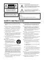
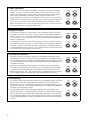
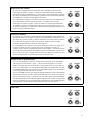
POWERED MULTIMEDIA SUBWOOFER
YST-MSW5
Active Servo
Technology
OWNER’S MANUAL
MODE D’EMPLOI
BEDIENUNGSANLEITUNG
BRUKSANVISNING
MANUALE DI ISTRUZIONI
MANUAL DE INSTRUCCIONE
GEBRUIKSAANWIJZING
Active Servo
Technology
POWERED MULTIMEDIA SUBWOOFER YST-MSW5
BASS
POWER
0
VOLUME
10
0
10
• Explanation of Graphical Symbols
The lightning flash with arrowhead symbol, within an
equilateral triangle, is intended to alert you to the
presence of uninsulated “dangerous voltage” within the
product’s enclosure that may be of sufficient magnitude to
constitute a risk of electric shock to persons.
CAUTION
RISK OF ELECTRIC SHOCK
DO NOT OPEN
CAUTION: TO REDUCE THE RISK OF
ELECTRIC SHOCK, DO NOT REMOVE
COVER (OR BACK). NO USER-SERVICEABLE
PARTS INSIDE. REFER SERVICING TO
QUALIFIED SERVICE PERSONNEL.
WARNING
TO REDUCE THE RISK OF FIRE OR
ELECTRIC SHOCK, DO NOT EXPOSE
THIS UNIT TO RAIN OR MOISTURE.
The exclamation point within an equilateral triangle is
intended to alert you to the presence of important
operating and maintenance (servicing) instructions in the
literature accompanying the appliance.
IMPORTANT!
Please record the serial number of this unit in the space below.
Model:
Serial No.:
The serial number is located on the rear of the unit.
Retain this Owner’s Manual in a safe place for future reference.
SAFETY INSTRUCTIONS
1
2
Read Instructions — All the safety and operating
instructions should be read before the unit is operated.
10 Power Sources — The unit should be connected to
Retain Instructions — The safety and operating
instructions should be retained for future reference.
11 Power-Cord Protection — Power-supply cords
3
Heed Warnings — All warnings on the unit and in
the operating instructions should be adhered to.
4
Follow Instructions — All operating and other
instructions should be followed.
5
Water and Moisture — The unit should not be used
near water – for example, near a bathtub, washbowl, kitchen sink, laundry tub, in a wet basement,
or near a swimming pool, etc.
6
Carts and Stands — The unit should be used only
with a cart or stand that is recommended by the
manufacturer.
6A An unit and cart combination
should be moved with care. Quick
stops, excessive force, and
uneven surfaces may cause the
unit and cart combination to overturn.
7
8
9
i
Wall or Ceiling Mounting — The unit should be
mounted to a wall or ceiling only as recommended
by the manufacturer.
Ventilation — The unit should be situated so that its
location or position does not interfere with its proper
ventilation. For example, the unit should not be situated on a bed, sofa, rug, or similar surface, that
may block the ventilation openings; or placed in a
built-in installation, such as a bookcase or cabinet
that may impede the flow of air through the ventilation openings.
Heat — The unit should be situated away from heat
sources such as radiators, stoves, or other appliances that produce heat.
a power supply only of the type described in the
operating instructions or as marked on the unit.
should be routed so that they are not likely to be
walked on or pinched by items placed upon or
against them, paying particular attention to cords at
plugs, convenience receptacles, and the point
where they exit from the unit.
12 Cleaning — The unit should be cleaned only as recommended by the manufacturer.
13 Nonuse Periods — The power cord of the unit
should be unplugged from the outlet when left
unused for a long period of time.
14 Object and Liquid Entry — Care should be taken so
that objects do not fall into and liquids are not
spilled into the inside of unit.
15 Damage Requiring Service — The unit should be
serviced by qualified service personnel when:
A. The power-supply cord or the plug has been
damaged; or
B. Objects have fallen, or liquid has been spilled
into the unit; or
C. The unit has been exposed to rain; or
D. The unit does not appear to operate normally or
exhibits a marked change in performance; or
E. The unit has been dropped, or the enclosure
damaged.
16 Servicing — The user should not attempt service
the unit beyond those means described in the operating instructions. All other servicing should be
referred to qualified service personnel.
17 Power Lines — An outdoor antenna should be
located away from power lines.
18 Grounding or Polarization — Precautions should be
taken so that the grounding or polarization is not
defeated.
FCC INFORMATION
1. IMPORTANT NOTICE: DO NOT MODIFY THIS
UNIT! This product, when installed as indicated in the
instructions contained in this manual, meets FCC requirements. Modifications not expressly approved by Yamaha
may void your authority, granted by the FCC, to use the
product.
2. IMPORTANT: When connecting this product to accessories and/or another product use only high quality shielded
cables. Cable/s supplied with this product MUST be used.
Follow all installation instructions. Failure to follow instructions could void your FCC authorization to use this product
in the USA.
3. NOTE: This product has been tested and found to comply
Compliance with FCC regulations does not guarantee that
interference will not occur in all installations. If this product
is found to be the source of interference, which can be
determined by turning the unit “OFF” and “ON”, please try
to eliminate the problem by using one of the following
measures:
Relocate either this product or the device that is being
affected by the interference.
Utilize power outlets that are on different branch (circuit
breaker of fuse) circuits or install AC line filter/s.
In the case of radio or TV interference, relocate/reorient
the antenna. If the antenna lead-in is 300 ohm ribbon lead,
change the lead-in to coaxial type cable.
with the requirements listed in FCC Regulations, Part 15 for
Class “B” digital devices. Compliance with these requirements provides a reasonable level of assurance that your
use of this product in a residential environment will not result
in harmful interference with other electronic devices.
If these corrective measures do not produce satisfactory
results, please contact the local retailer authorized to distribute this type of product. If you can not locate the appropriate retailer, please contact Yamaha Corporation of
America, 6600 Orangethorpe Ave, Buena Park, CA 90620
This equipment generates/uses radio frequencies and, if not
installed and used according to the instructions found in the
users manual, may cause interference harmful to the operation of other electronic devices.
The above statement apply ONLY to those products distributed by Yamaha Corporation of America or its subsidiaries.
For U.K. customers
If the socket outlets in the home are not suitable for the plug
supplied with this appliance, it should be cut off and an appropriate 3 pin plug fitted. For details, refer to the instructions
described below.
Note: The plug severed from the mains lead must be
destroyed, as a plug with bared flexible cord is hazardous if
engaged in a live socket outlet.
Special Instructions for U.K. Model
IMPORTANT
THE WIRE IN THE MAINS LEAD ARE COLOURED IN
ACCORDANCE WITH THE FOLLOWING CODE:
Blue: NEUTRAL
Brown: LIVE
As the colours of the wires in the mains lead of this apparatus may not correspond with the coloured markings identifying the terminals in your plug. Proceed as follows:
The wire which is coloured BLUE must be connected to the
terminal which is marked with the letter N or coloured
BLACK. The wire which is coloured BROWN must be connected to the terminal which is marked with the letter L or
coloured RED. Making sure that neither core is connected to
the earth terminal of the three pin plug.
CAUTION (FOR CANADIAN CUSTOMERS)
THIS CLASS B DIGITAL APPARATUS MEETS ALL
REQUIREMENTS OF THE CANADIAN INTERFERENCECAUSING EQUIPMENT REGULATIONS.
ATTENTION (POUR LES CONSOMMATEURS CANADIENS)
CET APPAREIL NUMERIQUE DE LA CLASSE B
RESPECTE TOUTES LES EXIGENCES DU REGLEMENT
SUR LE MATERIEL BROUILLEUR DU CANADA.
OBSERVERA
Apparaten kopplas inte bort från växelströmskällan (nätet)
så länge som den är ansluten till vägguttaget, även om
själva apparaten har stängts av.
ADVARSEL
Netspæendingen til dette apparat er IKKE afbrudt,
sålæenge netledningen siddr i en stikkontakt, som er t endt
– også selvom der or slukket på apparatets afbryder.
Prima di predisporre questo interruttore, staccare å spina
del cavo di alimentazione dell’apparecchio dalla presa di
corrente alternata di rete.
VAROITUS
Laitteen toisiopiiriin kytketty käyttökytkin ei irroita koko laitetta verkosta.
ii
System Example / Exemple de connexion / Anschlußbeispiel /
Systemexempel / Esempio di sistema / Ejemplo del sistema /
Aansluitingsvoorbeelden / ____________
Example 1
4
3
5
YST-MSW5
or
LINE IN
LINE OUT
ABOVE 150Hz
AUTO
POWER
ON OFF
LINE IN
LINE OUT
ABOVE 150Hz
6
STEREO
INPUT
OUTPUT
to
DC 14V
2
−
To Left
Speaker
+
POWER
YST-M10
PRESENCE
VOLUME
POWERED MONITOR SPEAKER
Actve Servo
Technology
SER NO.
Example 2
4
5
or
2
YST-MSW5
LINE IN
LINE OUT
ABOVE 150Hz
1
INPUT 1
INPUT 2
TO
LEFT
SPEAKER
Active Servo
Technology
POWER
OUTPUT
VOLUME
(ADJ. VOL)
TONE
DC 12V
1
AUTO
POWER
ON OFF
3
LINE IN
LINE OUT
ABOVE 150Hz
English
Italiano
1 Speaker System with Connecter for Subwoofer
2 3.5 mm stereo mini-plug cable (not include)
3 3.5 mm stereo mini-plug cable (Accessories)
4 Personal computer
5 Portable CD player
6 Speaker System with Built-in Amp.
1 Sistema diffusori con connettore per subwoofer
2 Cavo con minispina stereo di 3,5 mm (non incluso)
3 Cavo con minispina stereo di 3,5 mm (Accessori)
4 Personal computer
5 Lettore CD portatile
6 Sistema diffusori con amplificatore incorporato
Français
Español
1 Système de haut-parleurs avec borne pour subwoofer
2 Câble avec fiches mini-jack stéréo 3,5 mm
(Pas fourni)
3 Câble avec fiches mini-jack stéréo 3,5 mm
(Accessoires)
4 Ordinateur individuel
5 Lecteur de CD portatif
6 Enceintes actives (avec ampli intégré)
1 Sistema de altavoces con conector para altavoz de
subgraves
2 Cable con miniclavija estéreo de 3,5 mm
(no suministrado)
3 Cable con miniclavija estéreo de 3,5 mm
(Accesorios)
4 Ordenador personal
5 Reproductor de discos compactos portatil
6 Sistema de altavoces con amplificador incorporado
Deutsch
Nederlands
1 Lautsprechersystem mit Anschluß für Subwoofer
2 3,5 mm Stereo-Miniklinkenkabel
(Gehört nicht zum Lieferumfang)
3 3,5 mm Stereo-Miniklinkenkabel (Lieferumfang)
4 Personal-computer
5 Tragbarer CD-spieler
6 Lautsprechersystem mit eingebautem Verstärker
1 Luidsprekersysteem met aansluiting voor lagetonen-luidspreker
2 3,5 mm stereo ministekkersnoer (niet inbegrepen)
3 3,5 mm stereo ministekkersnoer (Accessoires)
4 Personal computer
5 Draagbare CD-speler
6 Luidsprekersysteem met ingebouwde versterker
Svenska
Chinese
1 Högtalare med utgång för lågbashögtalare
2 Kabel med 3,5 mm stereominikontakt
(medföljer ej)
3 Kabel med 3,5 mm stereominikontakt (Tillbehör)
4 Persondator
5 Portable CD-spelare
6 Högtalare med inbyggd förstärkare
1
2
3
4
5
6
2
Volume Adjustment
• If the system is connected to the YST-MSW5’s LINE OUT jack as shown in System
example 1 on page 1, set the YST-MSW5’s BASS control to the noon or one-o’clock
position and raise the volume control of the powered main speakers to the maximum.
Then, use the YST-MSW5’s VOLUME control to adjust the overall volume.
• If the YST-MSW5 is connected to an output jack for a sub-woofer on a powered main
speaker (such as a Yamaha YST-M15, YST-M7, etc.) as shown in System example 2 on
page 1, raise the VOLUME control of the YST-MSW5 to the maximum and set the
BASS control to the noon or one-o’clock position. Then, use the volume control of the
powered main speakers to adjust the overall volume.
BASS
0
VOLUME
10
0
BASS
0
10
VOLUME
10
0
10
Réglage du volume
• Si le système est branché à la borne LINE OUT du YST-MSW5 comme indiqué dans
l’exemple de connexion 1 de la page 1, réglez la commande BASS du YST-MSW5 en
position “midi” ou “13h” et réglez la commande de volume des enceintes actives sur le
niveau maximum. Servez-vous ensuite de la commande VOLUME du YST-MSW5 pour
ajuster le volume global.
• Si le YST-MSW5 est branché à une sortie pour subwoofer d’une enceinte active (telle
qu’un Yamaha YST-M15, YST-M7, etc.) comme indiqué dans l’exemple de connexion 2
de la page 1, réglez la commande VOLUME du YST-MSW5 au maximum et placez la
commande BASS en position “midi” ou “13h”. Utilisez ensuite la commande de volume
des enceintes actives pour ajuster le volume global.
BASS
0
VOLUME
10
0
BASS
0
10
VOLUME
10
0
10
Einstellen der Lautstärke
• Wenn das System mit der LINE OUT-Buchse der YST-MSW5 verbunden ist (siehe
Systembeispiel 1 auf Seite 1), müssen Sie den BASS-Regler der YST-MSW5 in die 12oder 1-Uhr-Position und die Lautstärke der Hauptlautsprecher auf den Höchtswert stellen. Anschließend können Sie die allgemeine Lautstärke mit dem VOLUME-Regler der
YST-MSW5 einstellen.
• Wenn Sie die YST-MSW5 mit dem Tieftöner-Ausgang eines aktiven Hauptlautsprechers (z.B. einen Yamaha YST-M15, YST-M17 usw.; siehe Systembeispiel 2 auf Seite
1), müssen Sie den VOLUME-Regler der YST-MSW5 auf den Höchstwert und den
BASS-Regler in die 12- oder 1-Uhr-Position stellen. Anschließend können Sie die allgemeine Lautstärke mit dem VOLUME-Regler des Hauptlautsprechers einstellen.
BASS
0
VOLUME
10
0
BASS
0
10
VOLUME
10
0
10
Volymreglering
• När systemet anslutits till linjeutgången LINE OUT på YST-MSW5 enligt systemexempel 1 på sidan 1: ställ volymreglaget BASS på YST-MSW5 i ett läge motsvarande
klockan tolv eller ett och volymreglaget på högtalarna med inbyggd förstärkare i läget
för maximal volymnivå. Använd därefter volymreglaget VOLUME på YST-MSW5 till
att reglera den sammanlagda volymen.
• När YST-MSW5 anslutits till en lågbashögtalarutgång på en huvudhögtalare med
inbyggd förstärkare (t.ex. Yamahas YST-M15, YST-M7, etc.) enligt systemexempel 2 på
sidan 1: ställ volymreglaget VOLUME på YST-MSW5 i läget för maximal volymnivå
och volymreglaget BASS i ett läge motsvarande klockan tolv eller ett. Använd därefter
volymreglaget på högtalarna med inbyggd förstärkare till att reglera den sammanlagda
volymen.
3
BASS
0
VOLUME
10
0
BASS
0
10
VOLUME
10
0
10
Regolazione del volume
• Se il sistema è collegato alla presa LINE OUT dello YST-MSW5 com o mostrato
nell'Esempio di sistema 1 a pagina 1, regolare il comando BASS dello YST-MSW5
sulla posizione corrispondente alle 12 o 1 di un'orologio e alzare al massimo il comando
del volume dei diffusori principali amplificati. Quindi usare il comando VOLUME dello
YST-MSW5 per controllare il livello globale del volume.
• Se lo YST-MSW5 è collegato ad una presa di uscita per subwoofer di un diffusore principale amplificato (come lo YST-M15, YST-M7, ecc. Yamaha) come mostrato
nell'Esempio di sistema 2 a pagina 1, alzare al massimo il comando VOLUME dello
YST-MSW5 e regolare il comando BASS sulla poszione corrispondente alle 12 o 1 di
un orologio. Quindi usare il comando del volume dei diffusori principali amplificati per
regolare il livello globale del volume.
BASS
0
VOLUME
10
0
BASS
0
10
VOLUME
10
0
10
Ajuste del volumen
• Si el sistema está conectado a la toma LINE OUT del YST-MSW5, como se muestra en
Ejemplo del sistema 1 de la página 1, ajuste el control BASS del YST-MSW5 a la posición de las doce o la una en punto, y aumente al máximo el nivel del control de volumen
de los altavoces principales con altavoz incorporado. Después, utilice el control
VOLUME del YST-MSE5 para ajustar el volumen global.
• Si el YST-MSW5 está conectado a una toma de salida para un altavoz de subgraves de
un altavoz principal con altavoz incorporado (como el YST-M15, YST-M7, etc.
Yamaha), como se muestra en Ejemplo del sistema 2 de la página 1, aumente al máximo
el nivel del control VOLUME del YST-MSW5 y ajuste el control BASS a la posición de
las doce o la una en punto. Después, utilice el control de volumen de los altavoces principales con amplificador incorporado para ajustar el volumen global.
BASS
0
VOLUME
10
0
BASS
0
10
VOLUME
10
0
10
Instellen van de geluidssterkte
• Als u een stel luidsprekers aansluit op de LINE OUT aansluiting van de YST-MSW5,
zoals aangegeven in Voorbeeld 1 op blz. 1, dan zet u de BASS regelaar van de YSTMSW5 in de middenboven-stand of iets daar voorbij (twaalf of één uur op de klok) en
draait u de volumeregelaar van de aangesloten luidsprekers met ingebouwde versterker
in de maximumstand. Vervolgens gebruikt u de VOLUME regelaar van de YST-MSW5
om de totale geluidssterkte naar wens in te stellen.
• Als u de YST-MSW5 aansluit op de lagetonen-uitgangsaansluiting van een stel hoofdluidsprekers met ingebouwde versterker (zoals de Yamaha YST-M15, YST-M7 e.d.) zoals aangegeven in Voorbeeld 2 op blz. 1, dan draait u de VOLUME regelaar van de YST-MSW5
in de maximumstand en zet u de BASS regelaar middenboven of iets daar voorbij (twaalf
of één uur op de klok). Vervolgens gebruikt u de volumeregelaar van de hoofdluidsprekers
met ingebouwde versterker om de totale geluidssterkte naar wens in te stellen.
BASS
0
VOLUME
10
0
BASS
0
10
VOLUME
10
0
10
CHINISE
•
BASS
0
VOLUME
10
0
10
•
BASS
0
VOLUME
10
0
10
4
Thank you for purchasing Yamaha’s YST-MSW5 Powered Multimedia Subwoofer. Yamaha’s Active Servo Technology offers exceptionally high performance.
Cautions
Connections & Controls
Please read the following operating precautions before
use:
Front Panel
• When disconnecting the AC power cord from an AC
receptacle, hold and pull the plug, not the power cord.
• If the YST-MSW5 is not going to be used for a while,
disconnect the AC power cord from the AC receptacle.
• Always disconnect the AC power cord from the AC
receptacle before making any connections.
• The YST-MSW5 does not contain any user serviceable
parts. Refer all servicing to your Yamaha dealer.
• Never open the cabinet. If a foreign object drops into
the set, contact your dealer, and do not use the
YST-MSW5. Otherwise, you may cause a fire.
• Do not expose the YST-MSW5 to temperature extremes,
direct sunlight, excessive dust, humidity, or vibration.
• Position the YST-MSW5 on a level, stable surface. Do
not drop the YST-MSW5, apply excessive force to
their controls, or put heavy items on top of them.
• Since this unit has a built-in power amplifier, heat will
radiate from the rear panel. Therefore, place the unit
apart from the walls, allowing a space of at least 10 cm
(3-15/16") above, behind and on the both sides of the
unit. Also, do not position with the rear panel facing
down on the floor or other surface.
• Do not obstruct the port with your hand or a foreign
object.
• To protect the YST-MSW5 speaker, avoid microphone
feedback, continuous and excessive output from electronic musical instruments, and excessive signal distortion.
• If the YST-MSW5 is located close to fluorescent or
neon lights, a slight hum may be heard. In this case,
relocate the YST-MSW5 away from the light.
• Although the YST-MSW5 speaker is magnetically
shielded, keep floppy disks and tapes away from them.
• The YST-MSW5 may cause picture distortion when
located close to a television or computer monitor. In
this case, move them away a short distance.
• Avoid sources of hum (transformers, motors). To prevent fire or electrical shock, do not expose to rain and
water.
• Do not use force on switches, knobs or cords. When
moving the YST-MSW5, first turn the YST-MSW5 off.
• Always turn the volume control counterclockwise
before starting to play the audio source: increase the
volume gradually to an appropriate level after the playback has started.
1 POWER switch and indicator: Press the POWER
CAUTION
The apparatus is not disconnected from the AC
power source as long as it is connected to the wall
outlet, even if the apparatus itself is turned off.
CAUTION (FOR CANADA MODEL): TO PREVENT
ELECTRIC SHOCK, MATCH WIDE BLADE OF
PLUG TO WIDE SLOT AND FULLY INSERT.
5
Refer to the illustrations on page 1.
switch to turn on the YST-MSW5; the power indicator
lights up. Press again to turn off. Turn down the
BASS and VOLUME controls before turning on and
off the YST-MSW5.
2 BASS control: Use this control to adjust the volume
of the YST-MSW5. Turn it clockwise to increase the
volume; counterclockwise to decrease it.
3 VOLUME control: Use this control to adjust the volume of the YST-MSW5 and other equipment connected to the rear panel LINE OUT jack.
Active Servo
Technology
POWERED MULTIMEDIA SUBWOOFER YST-MSW5
BASS
POWER
0
1
VOLUME
10
2
0
10
3
Rear Panel
4 LINE IN: This 3.5 mm jack is used to input signals to
the YST-MSW5.
5 LINE OUT: This jack is used to output the LINE IN
signal to the main speakers. The low frequencies of
the signal are cut before being output to the speakers.
This prevents small speakers from becoming overloaded.
6 AUTO POWER switch: When the AUTO POWER
switch is in the ON position, and no input signal is
received after 5–10 minutes, the power is switched off
automatically. (and the power indicator dims*) When
an input signal is received, the power is switched back
on automatically. When the AUTO POWER switch is
in the OFF position, this Auto power on/off function
doesn’t work.
* U.K. and Europe model only.
LINE IN
LINE OUT
ABOVE 150Hz
AUTO
POWER
ON OFF
4
5
6
Note: The power may switch off automatically when
the input signal level is very low. If this does occur,
increase the output level from the source device and
reduce the YST-MSW5 VOLUME control accordingly.
Volume Adjustment
Refer to page 3.
Type................................. Active Servo Technology
Output power ................. 15 W (100 Hz, 4 Ω at
T.H.D.=10%)
Input sensitivity.............. 45 mV (100 Hz, 4 Ω at 15 W)
Input impedance ............ 20 kΩ
Frequency response ....... 40 to 250 Hz (–10 dB)
Speaker unit ................... 12 cm (5") cone, magnetic shielding
Output impedance ......... 600 Ω
Output level .................... 45mV (at 45mV Rated Input)
Power consumption ....... 20 W
Power supply
U.S.A. and Canada models.........AC 120 V, 60 Hz
English
Specifications
Australia model ......................... AC 240 V, 50 Hz
U.K. and Europe models ........... AC 230 V, 50 Hz
General model ........................... AC 110/120/220/240 V,
50/60 Hz
Dimensions (W × H × D)
148 (5-13/16") × 283 (11-1/8") × 210 (8-1/4") mm
Weight ............................. 4 kg (8lbs. 13oz.)
Finish
YST-MSW5 W .......................... Computer white color
YST-MSW5 B ........................... Black color
Accessories
3.5 mm stereo mini-plug cable (1.8m) × 1
* Specifications subject to change without notice.
Troubleshooting
If the speakers fail to operate normally, check the following table. It lists common operation errors and simple measures
that you can take to correct problems. If a problem cannot be corrected, or the symptom is not listed, disconnect the AC
power cord and contact your authorized YAMAHA dealer or service center for help.
FAULT
No sound comes from
the speakers or subwoofer.
CAUSE
The AC power cord is not properly
plugged into the wall outlet.
The POWER switch is turned OFF.
Connections are faulty or incomplete.
The volume is set to minimum.
Noise.
The level of the signal being input is
too low.
Connections are faulty or incomplete.
CURE
Insert the AC power cord firmly into the wall outlet.
Turn ON the POWER switch (the indicator lights).
Make the connections again, firmly, or use a different cable.
Turn the subwoofer VOLUME control to the right
to increase the volume.
Turn the speaker VOLUME control to the right to
increase the volume.
Turn up the volume on the connected component.
Make the connections again, firmly, or use a different cable.
Noise is heard when the The power cord of this unit connected Connect the power cord to an UNSWITCHED AC
power is turned on.
to another unit’s SWITCHED AC OUT- OUTLET.
LET.
Make sure to use the POWER switch on this unit
to turn the power on and off.
Power is not supplied
The power plug is not securely conConnect it securely.
even though the POWER nected.
switch is ON.
No sound.
The volume is set to 0.
Turn the VOLUME control to right.
Speaker cables are not connected
Connect them securely.
securely.
Sound level is too low.
Speaker cables are connected incorrectly. Connect them correctly.
A source sound with few bass frequen- Play a source sound with bass frequencies. Turn
cies is played.
the VOLUME control to right.
It is influenced by standing waves.
Relocate the subwoofer or break up the parallel surface by placing bookshelves etc. along the walls.
Auto power on function
The POWER switch is turned off.
Turn the POWER switch on.
doesn’t work.
The source input signal is too low.
Raise the input signal level to appropriate level.
Auto power off function
The source input signal is too low.
Raise the input signal level to appropriate level.
activates unintentionally.
Power is turned on acci- The other equipment’s hum interrupts Relocate the YST-MSW5 or cable wiring. Otherdentally when Auto
(i.e. computer, digital device).
wise, do not use the Auto power function.
power function is set to
ON.
6
YAMAHA CORPORATION
Printed in China VY63010