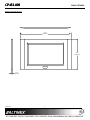
1
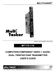
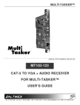
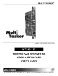
CP452CP452-009 MultiTouch™
MultiTouch™ InIn-Wall Widescreen Panel
Welcome!
We greatly appreciate your purchase of the CP452-009. We are sure you will
find it reliable and simple to use. Superior performance for the right price,
backed by solid technical and customer support is what ALTINEX has to offer.
User’s Guide
1.3 Cleaning
• Unplug the CP452-009 adapter before cleaning and clean only with a dry
cloth. Never use strong detergents or solvents such as alcohol or thinner.
Do not use a wet cloth or water to clean the unit. Do not open the unit to
clean.
We are committed to providing our customers with
Signal Management Solutions® to the most demanding audiovisual
installations at competitive pricing and we welcome you to join the ranks of
our many satisfied customers throughout the world.
1.4 FCC Notice
• This device complies with Part 15 of the FCC Rules. Operation is subject to
the following two conditions: (1) This device may not cause harmful
interference, and (2) this device must accept any interference received,
including interference that may cause undesired operation.
1. Precautions and Safety Warnings
Please read this manual carefully and heed all warnings. Keep this manual
handy for future reference. These safety instructions are to ensure the long
life of your CP452-009 and to prevent fire and shock hazards.
• This equipment has been tested and found to comply with the limits for a
Class A digital device, pursuant to Part 15 of the FCC Rules. These limits
are designed to provide reasonable protection against harmful interference
when the equipment is operated in a commercial environment. This
equipment generates, uses, and can radiate radio frequency energy and, if
not installed and used in accordance with the instructions found herein,
may cause harmful interference to radio communications. Operation of this
equipment in a residential area is likely to cause harmful interference in
which case the user will be required to correct the interference at his own
expense.
1.1 General
• There are no user serviceable parts inside. Qualified ALTINEX service
personnel must perform all service on the CP452-009.
1.2 Installation Precautions
• Place the CP452-009 in a dry area away from dust and moisture.
• To prevent fire or shock, do not expose to water or moisture. Do not place
in direct sunlight, near heaters, or heat-radiating appliances, or near any
liquid. Direct sunlight, smoke, or steam can harm internal components.
• Any changes or modifications to the unit not expressly approved by
ALTINEX, Inc. could void the user’s authority to operate the equipment.
• Handle the CP452-009 carefully. Dropping or jarring can cause damage.
• Do not pull any cables that are attached to the CP452-009.
• If not used for an extended period, disconnect from AC power.
2. Installation Procedures
Preparation
Step 1.
Make a list of the cabling requirements for the end-user application. What cable types are needed? For
example: CAT-5 for network connection, RS-232 for device control, power, VIDEO, USB, etc.
Step 2.
Determine the best location for the touch panel then prepare the cables based on type and length.
Step 3.
Installation - Hardware
Use the cutout template provided with the panel to make the opening in the wall. Test fit the panel into
the wall opening. Make sure the mounting wings are aligned vertically and the gap between the frame
and the wing is a little more than the wall thickness before fitting the panel into the wall.
Frame
Step 4.
Remove the panel and set it aside. Route all cables needed for the installation through the wall opening,
into the wall, and to the proper source/destination. For power, only use the power adapter provided.
Step 5.
Once the cables are routed, connect the power cable to the panel and verify the panel turns on
automatically. After the panel boots, disconnect the adapter from AC power.
Step 6.
Connect the remaining cables to the panel and insert the panel into the wall. Be careful not to bend the
cable connectors that are attached to the panel.
Step 7.
Make sure the wings are inside and behind the wall material. The panel fastens directly to the wallboard using
the attached, captive hardware. Tighten the mounting screws until each wing firmly "grabs" the wall.
Step 8.
Align the clips on the inside of the bezel with the mounting pins inside the frame and press firmly into place.
Step 9.
1) Set gap between frame
and wings to larger
than wall thickness.
2) Align mounting wings
vertically to insert.
Upload Application - Software
Connect the power adapter to AC power and wait for the panel to "boot" up; the panel boots automatically and launches
the AVSnap® initial setup application displaying system details. Follow the instructions to upload the application or quit the
setup application and use a USB drive to install the application.
WING
SCREW
PIN
Step 10.
Once all software has been installed, close all open applications and put a shortcut to the application in the startup folder. Run the COMMIT
batch file located on the desktop and restart the computer from the "Start" menu.
Step 11.
Verify the panel boots up and automatically launches the control software. The unit is now operational.
3. Limited Warranty/Return Policies
Please see the ALTINEX website at www.altinex.com for details on warranty and return policies.
400-0546-001
1
CP452
CP452-009
User’s Guide
4. Technical Specifications
Specifications are subject to change. See www.altinex.com for up-to-date information.
Features/Description
CP452-009
Details
LCD Size
LCD Resolution
LCD Colors
CPU
RAM
Solid State Drive
8.9 in
262k
CF Type II
USB 2.0
Type A F (4)
RS-232
DB9 M (2)
LAN
RJ-45 F (2)
3.5 mm F (1)
Mic In
3.5 mm F (1)
USB Panel Mount Cable
Body H x W x D **
4.6 x 8.3 x 1.5 in
(117 x 210 x 38 mm)
Bezel H x W x D **
6.5 x 11.2 x 0.3 in
(164 x 284 x 6 mm)
Touch Panel Weight
2.9 lb (1.3 kg)
System Shipping
Weight (approximate)
5.5 lb (2.5 kg)
0-40°C
Humidity
Electrical
CP452-009
External Connections
CE, FCC
USB 2.0 Voltage
4.4-5.2 VDC
USB 2.0 Current
100 mA max.
LAN Speed
UL/cUL
1000 Mbps (GbE)
RS-232 Input Range
Audio Line Out
+12 VDC, 5 A
HV Sync
Power Consumption
Optional Accessories
AC407-102
Silver Bezel (aluminum)
AC407-103
50 ft Power Extension
CB142-050
0.7 Vp-p nominal
Video Out
Type A F-M
Black Bezel (aluminum)
+/-15V
1 Vp-p nominal
RGB Analog
Paper Template for Wall Cutout
AC407-101
40,000 hrs (min.)
Table 2. CP452-009 Mechanical
3x3 in (75x75 mm)
White Bezel (aluminum)
-10°C / 50°C
10-90% non-condensing
MTBF (calculations)
Accessories Included
Cutout Template
6.2 x 10.5 x 0.06 in
(157 x 267 x 2 mm)
Storage T° Min/Max
Agency Approval
Power Adapter+ AC Cord
Frame H x W x D **
T° Operating
15-PIN HD F (1)
Audio Out
Safety (power adapter)
Steel/Black
1 GB
DC Jack (1)
EMC
Material/Color
Intel® Atom™ N270 1.6 GHz
+12 VDC In
Rear Mounting Holes *
CP452-009
WSVGA 1024x600
External Connections
Video Out (RGBHV)
Mechanical
+12VDC
TTL
(maximum from adapter)
60W max.
Table 3. CP452-009 Electrical
Table 1. CP452-009 General
** See application diagrams section for detailed views.
* Does not apply to wall installations.
400-0546-001
2
CP452
CP452-009
User’s Guide
5. About Your CP452-009 MultiTouch Widescreen Panel
The CP452 touch screen controller is specifically designed for in-wall installations. It
is ideal for a wide variety of control applications. Each controller is a computer
running Windows XP Embedded that includes these key features:
•
•
•
•
Touch Screen
COM port and 2 LAN ports
4 USB ports
AVSnap™ Professional AV System Integration Tool
The CP452 panel senses “touch” from a finger, stylus, pen, pencil, gloved finger, or
other tool. The touch screen is very accurate and responsive to the operator's input.
The CP452 incorporates effortlessly into any AV system.
The COM port can control virtually any serial device using standard RS-232
communication. The two LAN ports allow connectivity to a local area network or a
direct connection to another TCP/IP device. For added flexibility, consider the
ALTINEX AC301-201 TCP/IP to RS-232 Adapter. This adapter allows RS-232
communication through a standard LAN connection.
Shown here with a silver bezel.
The AC301-201 has both serial (DB9) and network (RJ-45) connections. The AC301-201 connects to a serial device using its DB9 connection, and to the LAN
using standard network cable. AVSnap, or other RS-232 communication software, can then be used to control the serial device using the IP address of the adapter
in place of the COM port. In this way, a single controller can be used to control any number of serial devices using their unique IP address.
The CP452 is designed for in-wall mounting. A paper template is provided for an accurate wall cutout. Simple blind screws provide hassle free installation.
AVSnap software is installed on the CP452 and provides a complete design environment for developing simple to sophisticated graphical user interfaces (GUIs)
and control software. AVSnap is pre installed on each CP452 making it easy to integrate into any control environment. Design high-quality GUIs with minimum
effort by way of user-friendly toolbars for buttons, volume controls, progress bars, and much more. AVSnap incorporates a simple programming language with an
organized interface that makes even complex programming code easy to read and maintain.
USB TYPE A F
(inside frame and behind bezel)
MOUNTING SCREWS (3)
(mounting wing adjustment)
MOUNTING PINS (4)
(bezel clips snap to these pins)
MIC IN
3.5 mm F
USB TYPE A F
LINE OUT
(inside frame)
3.5 mm F
COM2
DB9 M
(between USB and panel)
+12VDC DC IN
2.5 mm
USB
USB
TYPE A F (2)
TYPE A F (2)
POWER SWITCH
NETWORK
RJ-45 F (2)
400-0546-001
3
COM1
DB9 M
RGBHV VIDEO OUT
15-pin HD F
COMPACT FLASH
ACCESS PANEL
CP452
CP452-009
User’s Guide
6. Application Diagrams
Diagram 1: Typical Setup
400-0546-001
4
CP452
CP452-009
User’s Guide
Diagram 2: Dimensions
10.5"
[267 mm]
6.2"
[157 mm]
1.5"
[38 mm]
8.3"
[210 mm]
1.5"
[38 mm]
4.6"
[117 mm]
6.2"
[157 mm]
2.1"
[53 mm]
400-0546-001
5
CP452
CP452-009
User’s Guide
Diagram 3: Bezel Dimensions
11.2"
[284 mm]
6.5"
[164 mm]
0.3"
[6 mm]
400-0546-001
6
CP452
CP452-009
User’s Guide
7. Operation
7.3 Installing Files and Applications
The CP452 is designed for use in a fixed application where the system
boots up directly into the user application and does not allow access to the
operating system. The application and GUI interface are normally created
using a standard desktop computer and then installed onto the CP452 using
a USB drive or network connection.
The CP452 utilizes the Windows XP Embedded EWF to protect the
CP452’s internal memory from accidental or unauthorized changes. The
EWF appears to read and write from the internal drive, but executes
everything in RAM. All changes WILL be lost after reset or shutdown
unless the changes are committed to memory. Three batch files are
provided for direct control over the EWF and should be used cautiously.
Once set-up, the CP452 will work trouble free without user intervention.
7.1 Power Up and Shutdown
1. COMMIT.BAT – Write to hard drive
The CP452 boots automatically as soon as power is applied. There is no
need to press the power switch on the bottom of the unit. In most
installations, the system boots directly into the end-user application.
This batch file resides on the desktop and writes the RAM data onto
the hard drive for permanent storage while EWF is enabled. Close
open applications before running this batch file or the changes may
not be committed to memory.
The CP452 can be powered down using the shutdown/power off option
from the START menu, or directly from an AVSnap application using the
"App.Shutdown" function.
2. ENABLE.BAT – Turn on EWF
This batch file resides in the root directory and turns on the EWF. In
this mode, no changes made to the system are saved unless the
COMMIT batch file is executed. This is the default condition for all
CP452s.
7.2 Preparing Control Software
It is not recommended to design and create control software directly on
the CP452. In most situations, it is easier and faster to write and debug
control software on a standard desktop computer and then transfer the
completed file when ready. However, if the CP452 needs to be
programmed "in place", use an external USB keyboard and mouse. Simply
plug in the devices and wait for the system to recognize the new hardware
and load the drivers.
3. DISABLE.BAT – Turn off EWF
This batch file resides in the root directory and turns off the EWF. In
this mode, the system operates like a normal computer reading and
writing data directly to the hard drive.
WARNING
Remember, the CP452 employs the Enhanced Write Filter (EWF) to
protect the contents of the internal drive. Read the next section carefully
before attempting to install, create, or edit any data files or applications on
the CP452. If not executed properly, changes will be lost.
When the EWF is turned off, the user MUST shutdown the computer
properly. If power is turned off or lost without executing the normal
shutdown procedure, data can be lost, or corrupted, including the
BIOS and operating system (OS). If the BIOS or OS are damaged, the
entire system can become unusable.
The best way to create and edit on the CP452 is to use a USB drive plugged
into the bottom of the unit and make changes directly to the USB drive
then copy the final files to the CP452’s "C" drive.
7.3.1 Installing Large Files
If the application or file is too large for the available RAM, the operation
will be aborted. Use the disable batch file before installing the software.
Make sure to reset the EWF when done.
400-0546-001
7
CP452
CP452-009
User’s Guide
8. Troubleshooting Guide
We have carefully tested and have found no problems in the supplied CP452. However, we would like to offer suggestions for the following:
Symptom
Resolution
1. Verify the adapter is plugged into a working AC outlet and that the outlet has power. Use only the AC adapter
that was shipped with the unit.
Power Is Not On
2. Verify the DC power plug coming from the AC adapter is plugged all the way into the CP452.
3. If there is AC power to the adapter and the panel still does not turn on, the CP452 or the power adapter may
require service; call ALTINEX at (714) 990-2300.
1. Always make changes to the CP452 then run the COMMIT batch file on the desktop before shutting down or
restarting the CP452. A valid shutdown (Windows shutdown or restart) is needed to validate and make the
changes permanent. If power is turned off or lost with running a proper shutdown, all changes are lost.
Software/Files Are Missing
2. Any files that are open for editing must be closed before executing the COMMIT batch file.
For best results:
a. Close all applications and files.
b. Run the COMMIT batch file.
c. Restart the panel from the Windows Start menu.
400-0546-001
8