1
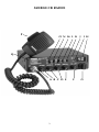
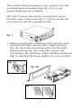
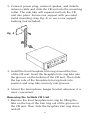
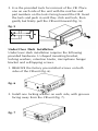
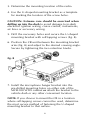
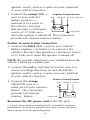
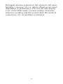
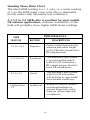
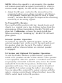
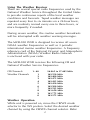
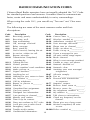
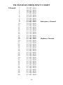
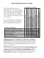
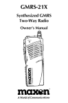
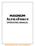
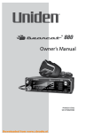
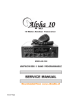
MCB-100 WXD
Professional 40 Channel
Mobile CB/Weather Radio
OWNER'S MANUAL
Downloaded from www.cbradio.nl
MCB-100 WXD SPECIFICATIONS
GENERAL
CB Channels:
Weather Channels:
CB Frequency Range:
Weather Frequency Range:
CB/Weather
Frequency Control:
Operating Temperature:
Input Voltage:
Channel Display:
DC Input Power:
Dimensions:
Weight:
External Speaker (optional):
RECEIVER
Receiving System:
Audio Output Power:
40
10
26.965 to 27.405 MHz
1
162.550 MHz
2
162.400 MHz
3
162.475 MHz
4
162.425 MHz
5
162.450 MHz
6
162.500 MHz
7
162.525 MHz
8
161.650 MHz
9
161.775 MHz
0
163.275 MHz
Phase Locked Loop Synthesizer
-30o C to +50o C
13.8V DC nominal, negative or
positive ground
Light Emitting Diode (LED)
5W
7" W x 7-3/8" D x 2" H
2 lbs., 9.3 oz.
4 W output @ 4 Ohms with
3.5 mm plug
AM Dual conversion
superheterodyne
4 W, 10% THD
TRANSMITTER
RF Output Power:
Output Impedance:
4 W (maximum FCC allowable)
50 Ohm unbalanced
Specifications are subject to change without notice.
I
PRODUCT DESCRIPTION
Thank you for choosing the Maxon MCB-100 WXD
Professional 40 Channel Mobile CB / Weather Radio.
Maxon's MCB-100 WXD is designed for either in-dash
or under/over dash installation, easy operation and is
one of the most reliable 40 channel Citizens Band/
weather radios available.
Package Contents:
Main CB unit
Deluxe handheld microphone
CB Unit and microphone mounting hardware
In-dash mounting collar
In-dash faceplate trim ring
In-dash rear support mounting strap
In-dash removal tools
Under /over dash mounting bracket w/mounting
hardware
Owner's manual
Copy of FCC Part 95, Subpart D
NOAA Weather Radio Network frequency
reference card
An external mobile antenna is required for use - antenna
is not included. Refer to Mobile Antenna Information
section for more information.
YOU DO NOT NEED AN FCC LICENSE TO OPERATE
THIS RADIO IN THE UNITED STATES. However, you
must know and be familiar with Part 95 of the FCC Rules
in regard to Subpart D of the Citizens Band Radio Service.
(A copy is enclosed with this unit).
Before operating your Maxon Citizens Band Radio, read this
Owner's Manual carefully. If you have a problem, refer to the
Troubleshooting section of this manual before returning your
radio for repairs.
II
TABLE OF CONTENTS
Specifications
Product Description
Package Contents
FCC Regulations
Performance Features
Controls and Functions
Installation Instructions
In-Dash Installation
Removing the In-Dash CB Unit
Under/Over Dash Installation
DC Power Supply Connection
Negative Ground System Connection
Positive Ground System Connection
Mobile Antenna Information
Antenna Tuning/SWR Meter Operation
Calibrating the SWR Meter
Standing Wave Ratio Chart
Operating Instructions
For CB Operation
To Transmit /To Receive
External Speaker Operation
PA System and Optional PA Speaker Operation
Using the Weather Receiver
Weather Operation
Radio Communication Codes
CB Channel Frequency Chart
Troubleshooting Chart
Warranty Statement
III
I
II
II
II
1
2
4
4
6
7
9
9
10
11
12
12
14
15
15
16
16
16
17
17
19
20
21
22
PERFORMANCE FEATURES
• Multifunctional analog meter measures and displays the
Standing Wave Ratio (SWR) of the CB antenna system;
actual RF output power when transmitting; and input signal
strength when receiving
• 40 CB Channels with 7 NOAA channels for receiving current
local National Weather Service broadcasts and 3 periodic
international marine weather channels
• Maximum legal output power (4 Watts)
• Dual mounting, for in-dash or under/over dash installation
• Direct access to Emergency CH 9 and Highway CH 19
• CB and weather channel selector knobs
• Dual-color LED identifies transmit and receive modes
• Public Address (PA) system circuitry (speaker not included)
• Automatic Noise Limiter (ANL) and noise blanker circuitry
switch reduces atmospheric static noise interference during
CB operation and reduces electrical impulse noise caused by
the vehicle's ignition
• SWR Meter calibration capability
• RF Gain control knob adjusts the receiving sensitivity of
the radio
• Front-mounted, deluxe microphone
• Display bright/dim switch
• Solid state components for years of trouble-free operation
• Highly sensitive, selective dual-conversion superheterodyne
receiver with tuned RF stage
• Last channel memory recalls last channel displayed
• Rugged, metal cabinet
• One year warranty
1
CONTROLS AND FUNCTIONS
A.
B.
C.
D.
E.
F.
G.
H.
I.
J.
K.
L.
M.
N.
O.
P.
Q.
Microphone Jack
Off/ On-Volume Control
Squelch Control
RF Gain Control: Adjusts the receiving sensitivity of the
radio
SWR Calibration Control: Manually calibrates the SWR
meter
CB/WX Mode Selector: Selects CB or weather operation
CB/WX Channel Selector
LED Channel display: Indicates the CB channel selected
Weather (WX) LED Indicator: Identifies weather mode
Receive (RX)/Transmit (TX) LED Indicator: Identifies
radio status
Display Bright / Dim Switch
CB-PA Switch: Position selects normal CB operation or
Public Address mode
NB/ANL-ANL-OFF Switch: Position selects noise blanker
with automatic noise limiter circuitry; ANL circuitry only;
or off
CH 9-NOR-CH 19 Switch: Position selects Emergency
CH 9; normal CB channels (1-40); or Highway CH 19
S/RF-SWR-CAL Switch: Position selects function of analog
meter: measuring radio input /output signal power
strength; measuring Standing Wave Ratio of antenna; or
entering SWR calibration mode
Front-mounted, Deluxe Microphone
Analog Meter: Measures and displays the Standing Wave
Ratio (SWR) of the CB antenna system; actual RF output
power when transmitting; and input signal strength when
receiving
Antenna Pigtail Jack: Located on back panel, not shown
PA Speaker Jack: Located on back panel, not shown
External Speaker Jack: Located on back panel, not shown
DC Power Cord Jack: Located on back panel, not shown
2
MOBILE CB RADIO
P
O N M L K J I H
Q
A B C D E
3
F
G
INSTALLATION INSTRUCTIONS
Your new MCB-100 WXD is designed to be installed
in-dash, under/over the dash or anywhere INSIDE your
vehicle. Safety and convenience should be your primary
considerations in deciding exactly where to locate
your CB radio.
CAUTION: Be sure the unit is located where it will
not interfere with the driver or impair access to any
controls necessary for the safe driving of the vehicle.
Before permanently installing the CB radio, connect
the wiring temporarily and make sure it is connected
properly and the CB unit is functioning. (Wiring instructions for power and antenna are located in this manual).
The radio's power and antenna connecting cables must
be routed and secured in such a manner as not to
interfere with the operation of the brake, accelerator
or other controls. Interference from either the CB unit
or its connecting cables may contribute to the loss of
control of the vehicle.
Hardware is provided for in-dash or under/over dash
installations. Use only the parts included with the CB
unit to ensure proper installation. The use of unauthorized parts can cause malfunctions.
In-Dash Installation
In-dash installation requires the following provided
hardware: mounting collar, front faceplate trim ring,
rear metal mounting strap, and microphone hanger
bracket.
4
The in-dash CB unit requires a rear support. Use the
provided metal mounting strap (fig. 4) or a rear
support bushing (not included).
DO NOT remove the factory pre-installed screws
from the sides of the radio (fig. 1). They lock the CB
unit securely into the mounting collar.
fig. 1
1. Before inserting the mounting collar into the dash,
push the side tabs inward with a slight pressure
(fig. 2a). Insert the mounting collar into the dashboard opening (fig. 2b). Select the proper tabs
according to the thickness of the dashboard material
(fig. 3) and bend them up slightly for a secure hold.
fig. 2a
fig. 2b
fig. 3
5
2. Connect power plug, external speaker, and mobile
antenna cable and slide the CB unit into the mounting
collar. The side tabs will expand and lock the CB
unit into place. Secure rear support with provided
metal mounting strap (fig. 4) or use a rear support
bushing (not included).
fig. 4
3. Install the front faceplate trim ring around the face
of the CB unit. Insert the faceplate trim ring tabs into
the grooves on the bottom of the CB unit. Then slide
the top side of the faceplate trim ring back into
position and snap tabs securely into grooves.
4. Mount the microphone hanger bracket wherever it is
most convenient.
Removing the In-Dash CB Unit
1. Remove the front faceplate trim ring by lifting the
tabs on the top of the trim ring out of the grooves in
the CB unit. Then slide the faceplate trim ring down
and off.
6
2. Use the provided tools for removal of the CB. Place
one on each side of the unit with the notches and
part numbers on the tools facing toward the CB. Insert
the tools and push in until they click and lock, then
gently but firmly pull the CB unit forward (fig. 5).
fig. 5
Under/Over Dash Installation
Under/over dash installation requires the following
provided hardware: U-shaped mounting bracket,
locking washers, retention knobs, microphone hanger
bracket and self-tapping screws.
1. REMOVE the factory pre-installed screws on both
sides of the CB unit (fig. 6).
fig. 6
2. Install one locking washer on each side, with grooves
facing away from the CB unit (fig. 7).
fig. 7
7
3. Determine the mounting location of the radio.
4. Use the U-shaped mounting bracket as a template
for marking the location of the screw holes.
CAUTION: Extreme care should be exercised when
drilling up into the dash to avoid damage to in-dash
electronic ignition wiring, cruise control, instruments,
air lines or accessory wiring.
5. Drill the necessary holes and secure the U-shaped
mounting bracket with self-tapping screws (fig. 8).
6. Position the CB unit between the mounting bracket
arms (fig. 8) and adjust to the desired viewing angle.
Secure by tightening the two retention knobs.
fig. 8
7. Install the microphone hanger bracket into the
pre-drilled mounting holes on either side of the
MCB-100 WXD cabinet or attach the bracket to the
vehicle dash or any other convenient location.
NOTE: If you choose to mount the CB in a location
where self-tapping screws cannot be used, determine
the most secure method of fastening the U-shaped
mounting bracket to that surface.
8
DC Power Supply Connection
The MCB-100 WXD is designed for 12V DC operation
in vehicles with negative (-) or positive (+) ground
electrical systems.
NOTE: Check your vehicle's ground requirements
before you begin the radio installation.
Trace the battery cable (attached to the vehicle's frame)
to the battery terminal post. If the battery terminal post
is marked with a minus (-) sign, it is a negative ground
system. If the battery terminal post is marked with a
plus (+) sign, it is a positive ground system.
Negative Ground System
Positive Ground System
NEGATIVE GROUND WIRE
(FASTEN TO METAL BODY
SOLENOID
OF VEHICLE)
POSITIVE WIRE (FASTEN TO METAL
BODY OF VEHICLE)
SOLENOID
12-VOLT
BATTERY
12-VOLT
BATTERY
EXAMPLE OF NEG. GROUND 12V DC
BATTERY CONNECTION - MOST
COMMERCIAL VEHICLES ARE THIS TYPE.
EXAMPLE OF POS. GROUND 12V DC
BATTERY CONNECTION - FEW
COMMERCIAL VEHICLES ARE THIS TYPE.
Your MCB-100 WXD should be connected using the
following steps:
Place the on/off-volume knob in the off position by
turning it counter-clockwise to detent. Unplug your
DC power cord.
Negative Ground System Connection
1. Connect the black GROUND wire to a metal part
of your vehicle's frame*.
NOTE: Be sure the metal part is not insulated from the
vehicle's frame by a plastic part.
2. Connect the red (to switched accessory) wire to a
source of voltage that turns on and off with the
9
ignition switch, such as a spare accessory terminal
in your vehicle's fuse box.
3. Connect the orange (Batt +) Negative Ground System
RED ORANGE BLACK (GROUND)
wire to your vehicle's
battery positive (+)
terminal or to a point in
the vehicle's fuse box
that provides a continuous
(BATT)
(GROUND)
source of 12 Volts even
when the ignition is turned off. This connection
provides last channel memory feature.
Positive Ground System Connection
1. Connect the black (Batt -) wire to your vehicle's
battery negative (-) terminal or to a point in the
vehicle's fuse box that provides a continuous source
of 12 Volts even when the ignition is turned off.
NOTE: Be sure the metal part is not insulated from the
vehicle's frame by a plastic part.
2. Connect the red (to switched accessory) wire to a
source of voltage that turns on and off with the
ignition switch, such as a spare accessory terminal
in your vehicle's fuse box.
Positive Ground System
3. Connect the orange
RED
GROUND wire to a
metal part of your vehicle's
frame*. This connection
provides last channel
memory feature.
(GROUND)
ORANGE BLACK
(BATT)
Reconnect the DC power cord to the DC jack.
* A good, direct metal-to-metal ground is essential for optimum
performance. For the best ground connection, remove any paint,
dust or grease from the grounding point.
10
MOBILE ANTENNA INFORMATION
Your Maxon MCB-100 WXD requires a vehicle mount
CB/weather antenna for operation. An antenna is
not included with your MCB-100 WXD because of
varying vehicle applications, individual needs, and
owner cost preferences.
You may use any standard 50 Ohm vehicle mount
CB/weather antenna system with a PL-259 connector.
Maxon antenna model WTA-4WP may be obtained
from your local Maxon CB distributor/retailer.
NOTE: When installing a mobile antenna, please
follow the antenna manufacturer's installation
instructions completely. Never operate your CB
radio without an antenna or with a broken antenna
cable. This can result in internal damage to your CB
circuitry.
• Connect the antenna securely to the unit's
antenna receptacle
• Mount the antenna as high on the vehicle as
possible - the more the antenna extends above
the roof, the better the reception
• If possible, mount the antenna in the center of
the surface you have chosen
• Keep the antenna cables away from noise sources
such as the ignition system, gauges, etc.
• Make sure you have a solid, metal-to-metal
ground
11
Antenna Tuning/SWR Meter Operation
Refer to the antenna manufacturer's installation manual
for the recommended installation procedure and tuning
specifications. Most antennas are factory tuned, however
the radio's performance can usually be improved by
slightly lengthening or shortening the antenna mast.
Optimum CB performance is obtained by tuning your
antenna system to the actual frequency of the RF signal
transmitted. Refer to the Standing Wave Ratio chart
(following) to interpret the SWR meter readings.
For optimum performance, it is recommended that
you tune the antenna's system to the most commonly
used CB channel. If you have no particular channel
preference, set your antenna's SWR for maximum
performance for Highway Channel 19 operation.
You will obtain a different SWR reading from one CB
channel to another. If you use all 40 CB channels, you
may have 40 different SWR readings. Usually, almost
all the CB transmissions will fall within an acceptable
range.
Calibrating the SWR Meter
To calibrate the SWR meter, place the S/RF- SWR-CAL
switch into the CAL (calibration) position. Using the
handheld microphone, press and hold the P-T-T bar
on the side, and use the SWR CAL control knob to
manually adjust the analog meter to the CAL mark
(the meter's top scale). Release the P-T-T bar. Now,
place the S/RF-SWR-CAL switch into the SWR position
for antenna tuning and performance measurements.
Press the mic's P-T-T bar and read the meter's SWR
(top scale) for the antenna's actual SWR measurement.
12
Prolonged antenna exposure to the elements (salt spray,
humidity, corrosion, etc.) or vehicle vibration can cause
degradation in performance. This may be indicated by
a rise in the SWR meter's normal reading. Check the
antenna's condition and the coaxial cable, RF electrical
connections, etc. if a problem is indicated.
13
Standing Wave Ratio Chart
The ideal SWR reading is a 1:1 ratio, or a meter reading
of 1 on the SWR meter's top scale (this is obtainable
mostly under radio laboratory test conditions).
A 1.5:1 to 2:1 SWR ratio is excellent for most mobile
CB antenna applications. Antenna installations in-thefield will probably show higher SWR meter readings.
SWR
RATIOS
PERFORMANCE
RATING
DESCRIPTION
1:1 to 1.5:1
Superior
Perfect match between the
antenna and cable length
to the CB radio transmitter's
RF output power.
1.5:1 to 2:1
Excellent
The antenna/cable system
is an outstanding match
with this CB transmitter's
RF output power; ideal for
most CB installations.
2:1 to 3:1
Good
The antenna/cable system
with this CB transmitter
will perform to spec under
most normal conditions.
Higher than
3:1
Inefficient
Requires antenna system's
mounting hardware or
ground inspected; or the
antenna system adjusted,
or replaced.
14
OPERATING INSTRUCTIONS
Having properly installed and wired your new CB
and connected the antenna, you are now ready to
adjust your radio for optimum reception and voice
transmission.
For proper operation, the radio's microphone must be
connected to the unit. Insert the microphone plug into
the microphone jack (MIC). Push inward and tighten
the plug's locking nut.
NOTE: If you choose to remove the microphone and
cord for storage, be sure to unscrew the locking nut
then gently pull out the microphone plug to prevent
damage to the microphone cord.
For CB Operation
1. Turn the power on and adjust the volume to the
desired listening level. Set the CB-PA switch to the
CB position, and the CB/ WX mode selector knob to
the CB mode position.
NOTE: Verify that the CH 9-NOR-CH 19 switch is in
the NOR (normal) position, and the S/RF-SWR-CAL
switch is set to S/RF.
2. Use the CB channel selector knob to select the
desired channel. To use Emergency CH 9 or
Highway CH 19, set the CH 9-NOR-CH 19
switch to the desired position.
3. To reduce undesirable background noise, select a
channel where no signals are present, or wait until
signals cease on your channel. Rotate the squelch
control clockwise until the background noise ceases.
15
NOTE: When the squelch is set properly, the speaker
will remain quiet until a signal is received. In order to
receive weak signals, do not set the squelch too high.
4. Adjust the RF gain control to the desired level. In
congested urban areas where reception interference
is the greatest, reduce the RF gain. In rural or open
country, increase the RF gain to improve the receiving
sensitivity of incoming signals.
To Transmit/To Receive
Press and hold the push-to-talk bar. Speak slowly and
clearly in a normal voice, two to three inches from the
microphone. When transmitting, the RX/TX LED will
glow red. To Receive - release the push-to-talk bar.
When receiving or "standing by" the RX/TX LED will
glow green.
External Speaker Operation
To connect an optional external speaker, locate the
external speaker jack on the rear of the unit and insert
the speaker plug into the jack. The radio's internal
speaker will be silenced when an external speaker
is engaged.
PA System and Optional PA Speaker Operation
To use the Public Address system feature, you must
install a PA speaker outside of the vehicle. (This speaker
is not supplied). After the speaker is installed and wires
are properly connected to the PA jack, move the switch
marked CB-PA to the PA position. At this time, CB
operation will cease. You are now ready to broadcast
through the PA system using the radio's microphone.
You can adjust the external PA output volume with the
radio's volume control knob. When finished, move the
CB-PA switch back to the CB position.
16
Using The Weather Receiver
There are several special radio frequencies used by the
National Weather Service throughout the United States
to provide continuous reports of the local weather
conditions and forecasts. Taped weather messages are
repeated every four to six minutes on a 24-hour basis,
and are routinely revised every one to three hours, or
more frequently if needed.
During severe weather, the routine weather broadcasts
will be interrupted with weather warning messages.
The MCB-100 WXD is designed to receive all seven
NOAA weather frequencies as well as 3 periodic
international marine weather frequencies. A frequency
reference card of the National Oceanic and Atmospheric
Administration (NOAA) Weather Radio Network
is enclosed with your radio.
The MCB-100 WXD receives the following CB and
National Weather Service frequencies:
CB Channels
Weather Channels
1 - 40
1
2
3
4
5
6
7
8
9
0
26.965 to 27.405 MHz
162.550 MHz
162.400 MHz
162.475 MHz
162.425 MHz
162.450 MHz
162.500 MHz
162.525 MHz
161.650 MHz
161.775 MHz
163.275 MHz
Weather Operation
While unit is powered on, move the CB/WX mode
selector to the WX postion. Select the desired weather
channel by using the CB/WX channel selector. Refer
17
to the NOAA Weather Radio Frequency card to locate
the proper weather channel for your current geographic
location. The WX LED will glow green when the
weather receiver is active.
Re-adjust the volume if necessary.
To resume normal CB operation, simply turn the
CB/WX selector to the CB position.
18
RADIO COMMUNICATION CODES
Citizens Band Radio operators have universally adopted the "10" Code
for standard questions and answers. It enables them to communicate
faster, easier and more understandably in noisy surroundings.
When using the code 10-1, you would say "Ten one" not "One zero
one".
The following are some of the most common codes and their
descriptions.
Code
10-1
10-2
10-3
10-4
10-5
10-6
10-7
10-8
10-9
10-10
10-11
10-12
10-13
10-16
10-17
10-18
10-19
10-20
10-21
10-22
10-23
10-24
10-25
10-26
10-27
10-28
10-29
10-30
10-32
10-33
10-34
10-35
Code
Description
Description
10-36 Correct time is____________.
Receiving poorly.
10-37 Wrecker needed at _________.
Receiving well.
10-38 Ambulance needed at________.
Stop transmitting.
10-39 Your message delivered.
OK, message received.
10-41 Please turn to channel______.
Relay message.
10-42 Traffic accident at__________.
Busy, stand by.
Out of service; leaving the air. 10-43 Traffic tie-up at_____________.
10-44 I have a message for you.
In service, subject to call.
10-45 All units within range report.
Repeat message.
10-50 Break channel.
Transmission completed,
10-60 What is next message number?
standing by.
10-62 Unable to copy; use phone.
Talking too fast.
10-63 Network directed to.
Visitors present.
Advise weather/ road conditions. 10-64 Network clear.
10-65 Awaiting your next message/
Make pickup at__________.
assignment.
Urgent business.
10-67 All units comply.
Anything for us?
Nothing for you; return to base. 10-70 Fire at ___________________.
10-71 Proceed with transmission
My location is__________.
in sequence.
Call by telephone.
Report in person to________. 10-77 Negative contact.
10-81 Reserve hotel room at________.
Stand by.
10-82 Reserve room for___________.
Completed last assignment.
10-84 My telephone number is______.
Can you contact?
10-85 My address is______________.
Disregard last information.
I am moving to channel_____. 10-91 Talk closer to microphone.
10-93 Check my frequency on this
Identify your station.
channel.
Time is up for contact.
Does not conform to FCC rules. 10-94 Please give me a long count.
10-99 Mission completed; all units
I will give you a radio check.
secure.
Emergency traffic.
10-200 Police needed at____________.
Trouble at this station.
Confidential Information.
19
CB CHANNEL FREQUENCY CHART
Channel:
1
2
3
4
5
6
7
8
9
10
11
12
13
14
15
16
17
18
19
20
21
22
23
24
25
26
27
28
29
30
31
32
33
34
35
36
37
38
39
40
26.965
26.975
26.985
27.005
27.015
27.025
27.035
27.055
27.065
27.075
27.085
27.105
27.115
27.125
27.135
27.155
27.165
27.175
27.185
27.205
27.215
27.225
27.255
27.235
27.245
27.265
27.275
27.285
27.295
27.305
27.315
27.325
27.335
27.345
27.355
27.365
27.375
27.385
27.395
27.405
20
MHz
MHz
MHz
MHz
MHz
MHz
MHz
MHz
MHz
MHz
MHz
MHz
MHz
MHz
MHz
MHz
MHz
MHz
MHz
MHz
MHz
MHz
MHz
MHz
MHz
MHz
MHz
MHz
MHz
MHz
MHz
MHz
MHz
MHz
MHz
MHz
MHz
MHz
MHz
MHz
Emergency Channel
Highway Channel
TROUBLESHOOTING CHART
If you experience problems
with your CB please refer to
this Troubleshooting Chart.
POSSIBLE PROBLEM
POSSIBLE SOLUTIONS
Check power cable connection
Check fuses (in-line and main junction block)
Check squelch adjustment
Check power on / off control
Change to active channel
Check antenna connection
Fully depress Push-To-Talk bar
Check microphone connection
Check CB/WX selector knob position
This CB radio has been
manufactured in accordance
with Maxon's exacting quality
control standards. It should
be handled with reasonable
care. Avoid exposing it to dirt
or moisture.
No sound or channel LED lights
Channel LED lights, but no sound
No voice reception
Poor reception
Unclear reception
Transmission problems
WARNING: DO NOT ATTEMPT TO MAKE ANY INTERNAL
ADJUSTMENTS. Any internal adjustments must be made only
by qualified technical personnel. Internal adjustments and/or
modifications can lead to illegal operation as defined by FCC
Rules and Regulations, Part 95. Illegal operation can result in
serious consequences.
CAUTION: The fuse included with this unit is an important safety
feature which must not be circumvented. Removal of this fuse
or the use of a fuse rated higher than supplied may result in
overheating and/or fire and consequential damage to the
unit or vehicle. If a replacement fuse burns out, have the unit
inspected and repaired by a qualified service technician.
21
LIMITED WARRANTY STATEMENT
The Consumer Products Division of Maxon America, Inc., (hereinafter
referred to as "Maxon"), warrants that its Products and their included
accessories will be free from defects in workmanship or materials under
normal use for a period of one (1) year from date of purchase by the original
end user, provided that the buyer has complied with the requirements
stated herein.
If the Product fails to function under normal use because of manufacturing
defect(s) or workmanship during the one (1) year period following the date
of purchase, it will be replaced or repaired at Maxon's option at no charge
when returned to the place of purchase. The defective unit must be
accompanied by proof of the date of purchase in the form of a sales receipt.
Maxon's sole obligation hereunder shall be to replace or repair the product
covered in this Warranty. Replacement, at Maxon's option, may include a
similar or higher-featured product. Repair may include the replacement of
parts or boards with functionally equivalent reconditioned or new parts or
boards. Replaced parts, accessories, batteries or boards are warranted for the
balance of the original time period. All replaced parts, accessories, batteries
or boards become the property of Maxon America, Inc.
Maxon shall have no obligation to make repairs or to cause replacement
required which result from normal wear and tear or is necessitated in whole
or in part by catastrophe, the fault or negligence of the user, improper or
unauthorized alterations, repairs to the Product, incorrect wiring, use of the
Product in a manner for which it was not designed, or by causes external to
the Product. This warranty is void if the serial number is altered, defaced or
removed.
The purchaser shall provide for removal of the defective Product and
installation of its replacement.
THE EXPRESS WARRANTIES CONTAINED HEREIN ARE IN LIEU OF
ALL OTHER WARRANTIES, EITHER EXPRESSED OR IMPLIED OR
STATUTORY, INCLUDING, WITHOUT LIMITATION, ANY WARRANTY
OF MERCHANTABILITY OR FITNESS FOR A PARTICULAR PURPOSE.
FOR ANY PRODUCT WHICH DOES NOT COMPLY WITH THE
WARRANTY SPECIFIED, THE SOLE REMEDY WILL BE REPAIR
OR REPLACEMENT. IN NO EVENT WILL MAXON AMERICA, INC.
BE LIABLE TO THE BUYER OR ITS CUSTOMERS FOR ANY
DAMAGES, INCLUDING ANY SPECIAL, INCIDENTAL, INDIRECT OR
CONSEQUENTIAL DAMAGES, OR THE LOSS OF PROFIT, REVENUE
OR DATA ARISING OUT OF THE USE OF OR THE INABILITY TO USE
THE PRODUCT.
This warranty is void for sales and deliveries outside of the U.S.A.
22
Thank you for choosing Maxon!
For more information, contact:
Maxon America, Inc.
Consumer Products Division
10828 NW Air World Drive
Kansas City, Missouri 64153
Phone: 1-800-821-7848, Ext. 399
Fax: 816/891-8815
or explore our website: www.maxonusa.com
Printed in Thailand
U.S. P/N: 680-090-0103 Rev. B