1
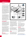
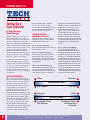
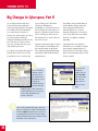
NOVEMBER/DECEMBER 1999
VOLUME 10
NUMBER 6
Extron’s New VSC 150 Advances
the Technology of Scan Conversion
Extron’s new VSC 150 high-resolution
computer-to-video scan converter is the
newest member of our VSC product line.
The VSC 150 provides the following new
features: variable horizontal & vertical
sizing, three user-selectable encoder filters
to adjust image sharpness, IR remote
control, RS-232 control with Extron’s
Simple Instruction Set™, and a rackmountable enclosure. The VSC 150 is
ideal for scan converting computer images
from up to 1152 x 900, horizontal scan
rates from 24 to 70 kHz and vertical scan
rates from 50 to 120 Hz, down to NTSC
or PAL video. Applications include videoconferencing, recording, or viewing
computer-video images on a TV monitor
or other display.
APPLICATIONS
The VSC 150 is ideal for many applications, such as videoconferencing; video
production & editing; videotaping of computer-video; and
displaying computer presentations on NTSC or PAL displays.
Most videoconference presenters use computer programs when
they make presentations, so videoconferencing systems
frequently incorporate computers as video and/or audio sources
during a call. The computer outputs high-resolution computervideo signals that are incompatible with the lower-resolution
video input on the videoconferencing unit. Computer-video
images must be scan converted to NTSC/PAL video images,
which are accepted by the videoconferencing unit. Once
computer-video images have been scan converted, they may also
be recorded on videotape.
continued on page 2
Grooving with the Electrohome Blues Band
In our continuing series on the
“Battle of the Bands” at
INFOCOMM ’99 in Orlando,
Florida, we’ve moved the spotlight
to the Electrohome Blues Band. In
dapper suits and fedoras made by the
same company that manufactured the
Blues Brothers’ fedoras, the
Electrohome Blues Band kicked off
the live music at Point Orlando.
In the heat of Florida’s summer, the
Electrohome Blues Band played
R&B as well as the blues at Extron’s
Ship Wreck Bash. The band kept the
crowd cool with lively renditions of
Mojo, Meet Me With Your Black
Drawers On, Sweet Home Chicago,
and Stoop Down. Band members
included Wayne Bickley on drums,
Paul Comella on lead/rhythm guitar,
Jerry Dixon on lead/rhythm guitar,
continued on page 3
In This Issue:
Tweeker Use #53......................................................3
Naming Extron Interfaces........................................4
New Digital Graphic Interfaces for Projectors ........5
New Products ..........................................................6
Tech Corner ............................................................8
Unique Techniques: Courthouse of the Future ......10
New News..............................................................14
Big Changes in Cyberspace, Part II ......................16
EXTRONEWS NOV/DEC 1999
VSC 150
continued from page 1
Hi Carol
Hi Carol
Two useful features of the VSC 150 are its IR
remote control and genlock capability. During
a videoconference, IR control allows the
presenter to remotely make changes to the
VSC 150, making the presentation more
effective and efficient. The genlocking capability allows the VSC 150 to be genlocked
with other devices for seamless vertical
interval switching. Genlocking is a useful
feature for videoconferencing applications
because switching glitches are processed as
motion by CODECs, leading to on-screen
residual video. Genlocking provides glitchfree switching, eliminating loss of sync to the
CODEC; this helps avoid dropped calls that
may result from loss of sync with some
videoconferencing systems.
Infrared System
Remote
External Genlock
Timing
Outputs
GE
The VSC 150 offers you extensive control
over image quality. Two user-selectable levels
of horizontal filtering minimize detail loss,
and three user-selectable levels of vertical
filtering reduce flicker. Three user-selectable
encoder filters provide you with different
levels of overall image sharpness to choose
from for the best possible picture.
The VSC 150 provides horizontal & vertical
sizing, zoom, and horizontal & vertical
centering/pan controls. The VSC 150’s
extensive picture control options allow you to
size computer images upward to fill the entire
screen and to zoom in to produce clear,
detailed close-ups. In the zoom mode, the
horizontal and vertical shift controls become
variable pan controls, allowing detailed
imaging and panning of the image. Freeze
mode allows you to freeze any frame on the
display.
REMOTE CONTROL
An IR remote is provided for convenient
control of all functions excluding
2
NL
Terminator
K
OC
IN
Y
B-
Projector (RGBHV)
B/
Y
G/
OU
Y
R-
T RS
-232
or
R/
S
A
0.3
0V
-24
100
C
MA
VG
60
50/
I
N
P
U
T
S
PAL OUT
75 OHM
VIDE
V
O
O
U
O
T
VIDE
P SU
T
S
S-
VIDE
RG
R-
O
H
B
Y/Y
Y/B-
A
Hz
Video Editor
(Component)
VSC 150
Video Outputs
Composite
Video
For any environment utilizing professional
video production and editing effects, the
VSC 150 is ideal for applications requiring
computer-video, such as backgrounds or text,
to be seamlessly combined with video for
recording. For video production, the VSC 150
may be genlocked with other devices in a
production system, allowing for seamless
switching of multiple sources. For video
editing, the VSC 150 scan converts computervideo down to NTSC/PAL component video
for output to a video editing bay.
PICTURE ADJUSTMENTS
RS-232 Control
S-video
VGA Input
or
Mac Input
Videoconferencing
System
VCR
NOTE:
Only one S-video or component
video or RGB device may be
connected in addition to the
composite video device and
local monitor.
genlocking. The IR remote includes three
memory preset locations. Each memory
location stores size, zoom, panning,
centering, and filter settings for a specific
zoom setting. The memory locations allow
you to set up an image ahead of time and
recall that specific set-up instantaneously
during a presentation. These convenient
memory locations may be crucial when a
variety of detailed images are shown during
a videoconference.
presets to customize, and the remaining
30 locations are factory-loaded,
permanent presets.
For system integration, the VSC 150 offers
RS-232 control. All functions except
genlock are RS-232 controllable with
Extron’s Simple Instruction Set (SIS™).
RS-232 control is available via third-party
control or Extron’s Windows®-based control
program.
CONNECTIONS
MEMORY
The VSC 150’s memory feature automatically saves and recalls size, zoom,
panning, centering, and filter settings for
up to 60 user/factory memory preset
locations. There are 30 user memory
The VSC 150 includes 24-bit color
sampling, which provides 8 bits per color
for accurate 16.8 million color reproduction. The rack-mountable VSC 150 is
housed in a 1U high, 1/2 rack width
enclosure and features a 100-240VAC,
50/60 Hz, internal power supply.
The VSC 150 features 15-pin HD and
15-pin D input/loop-out connectors for easy
connection to any Macintosh or IBMcompatible computer and a local monitor.
The passive local monitor output allows you
to display images on a preview monitor. The
VSC 150 offers composite video, S-video,
component video, and RGBHV output
formats.
The VSC 150 (part number: 60-312-01)
lists for $2195.00 (US Dollars).
http://www.extron.com/product/product.asp?id=vsc150
EXTRONEWS NOV/DEC 1999
ExtroNews
Battle of the Bands
continued from page 1
™
President
Andrew Edwards
V.P., Finance
Ed Ellingwood
V.P., Operations
Bob Nichols
V.P., Product Development
Dave Pincek
V.P., R&D
Brian Taraci
V.P., Engineering
Steve Somers
V.P., Human Resources
Joanne Grush
V.P., Information Technologies
Ivan Perez
Dan Rubicini on bass guitar, Bill
Speer on keyboard, and Frank “B.B.”
Weathers, Jr. as lead vocalist. Rubicini
has ably taken over the bass guitar
position, inheriting it from Peter
Polfuss, who recently retired.
With Bickley based in California,
Comella in New York, Dixon in New
Mexico, Rubicini and Speer in
Canada, and Weathers in Washington,
D.C., practice time was scarce. “We
performed for the Microsoft Users’
Group in Palm Springs the weekend
before INFOCOMM ’99,” says
Bickley, “It was a successful evening,
and we used it as a practice session to
put together a few songs.”
The Electrohome Blues Band has
been performing at Extron’s annual
party since INFOCOMM ’96 in
Philadelphia. Over the past few years,
the Electrohome Blues Band has
become increasingly popular. The
band even has their own CD, which
they sell at the charity fundraisers
they perform at—with all profits
going to charitable causes.
Extron looks forward to the
Electrohome Blues Band’s return
performance at INFOCOMM 2000 in
Anaheim, CA!
Director of Sales
Jeff Gibson
Director of Marketing
Lee Dodson
PR/Media Manager
Rosia Senh
Technical Editors
Pat Charlton, Chris Elmore, Mike Fitzgerald,
Roger McCarten, Jim Scrivner, Joe da Silva
Graphic Designers
Jill Streit, Cyme Azar
Technical Illustrator
Randy Drumm
Technical Writer
June Lee
We welcome your comments and contributions!
Please submit ideas to Marketing Dept.
714.491.1500 • 800.633.9876
ExtroNews is published by Extron Electronics/
RGB Systems Inc. 1230 South Lewis Street,
Anaheim, CA 92805. All rights reserved. No
portion of this newsletter may be reproduced in
any form without written permission from Extron
Electronics. Every effort has been made to
ensure accuracy in content; however, Extron
assumes no responsibility for errors and
omissions in the information provided herein.
ExtroNews is sent free of charge to communication
industry professionals and end-users. Send
address changes, requests for copies, and
editorial correspondence to: Marketing Dept.,
Extron Electronics, at the address above, or call
714.491.1500 or 800.633.9876; FAX
714.491.1978; Email: [email protected]
Printed in the United States of America.
For Halloween,
Stephen Hosik of
Intellisys in Irvine, CA
made his mark on Extron
Tweeker history. Stephen
ingeniously carved
Extron's S3 logo into his
pumpkin – quite a
visual treat for Tweeker fans!
Send us your photograph of how you use the Tweeker.
If we publish it in a future issue of ExtroNews,
we’ll give you a free VTG 150.
Send entries along with an explanation to:
Extron Tweeker Contest
1230 S. Lewis Street
Anaheim, CA 92805
3
EXTRONEWS NOV/DEC 1999
How Extron Names Interfaces
by Jeff Gibson,
Director of Sales
To provide interfacing solutions for all
of your A/V applications, Extron has
created a complete line of interfaces
over the years. With such a wide
product range, the letters and numbers
that make up an interface’s name might
seem confusing until you understand how Extron’s numbering
system works.
The first part of an interface’s
name, “RGB”, designates it as
an interface, and the second part
of the name uses a numbering
system that has developed throughout
our history. We use a three-digit
numbering system for interfaces, with
the first digit always indicating the
series to which the interface belongs.
Have you ever noticed that the names
of our dedicated interfaces end in odd
numbers, such as the RGB 103xi and
1 = RGB 100 series
xi = ADSP
Interface
TM
Odd number = dedicated
the RGB 109xi? Conversely, the names
of our universal interfaces end in even
numbers, such as the RGB 190 and
RGB 130xi. The “xi” designation
indicates that these interfaces provide
Extron’s exclusive Advanced Digital
Sync Processing (ADSP™).
4
GENERAL NUMBERING SCHEME
Now let’s talk about the specific
interface numbers, digit by digit. As
mentioned earlier, the first digit of
Extron’s interface names indicates the
interface series to which it belongs—1
for the 100 series, 2 for the
202 series, and so forth.
5 = RGB 500 series
5 = HD15 connector
JEFF GIBSON
interface uses a 15-pin HD input
connector instead of the standard 9-pin D
input connector. For example, the
RGB 150xi and RGB 550 feature 15-pin
HD input connectors.
Even number = universal
Interface
Previously all Extron interfaces used
9-pin D input connectors. The versatile
9-pin D connector is compatible with
any computer using one of Extron’s
high-quality laptop breakout cables,
monitor breakout cables or MBC
buffers. As laptops have become more
commonplace in boardrooms and
training centers,
Extron added the
option of a 15-pin
HD connector on
our interfaces.
Although 9-pin input connectors still
have more overall advantages within an
A/V system, we are now offering a 15pin HD input connector on some interfaces to provide solutions for plug-andplay applications. How can you tell if
an interface has a 15-pin HD input
connector? For both our RGB 100 and
500 series, the number “5” appearing as
the second digit indicates that the
Extron also offers over 100 Architectural
Adapter Plates (AAPs), which feature
various audio or video signal pass-through
connectors, such as BNCs, mini-DIN, 15pin HD, 3.5 mm captive screw terminal,
and RJ-45. For our RGB 100, 400 and
500 series, the number “8” as the last digit
indicates the option of Architectural
Adapter Plates (Note: The RGB 118 does
not follow this guideline). For example,
the RGB 158xi and RGB 508 provide
openings for optional AAPs.
1 = RGB 100 series
5 = HD15 connector
8 = Architectural Adapter Plates
xi = ADSP TM
Interface
Even number = universal
As Extron continues providing interfacing solutions to meet your needs, we
will continue to follow our numbering
system. By understanding how Extron’s
interface numbering system works, you
will be able to quickly identify an
interface’s features and select the right
solution for your application.
EXTRONEWS NOV/DEC 1999
New Digital Graphics
Interfaces for Projectors –
Plugging into a Computer Very Near You
by Steve Somers,
V.P. Engineering
Whether you are new to image projection technology or a “second-generation road warrior”, using digital displays that connect to digital data ports
will rapidly become the norm. In barely the course of a year, flat panel
desktop monitors are finding their way onto our desktops or at least into the
preponderance of our next display purchase. So it goes with the everexpanding gaggle of portable data projectors. Is the digital connection to
monitors and projectors necessary or is it just technology chic?
DOOMED TO REPEAT HISTORY
Ready for a surprise? Digital interfacing
is not new. We’ve come full circle from
the days of the CGA and EGA graphics
interfaces. Both are comprised of digital,
TTL (5 volt Transistor Transistor Logic)
style formats capable of conveying a
limited number of colors at low cost.
The accompanying CRT monitor
matched the computer output with a
decoder system capable of converting
the digital signals to analog RGB.
Signals were solid and setup simple.
Of course, at that time projector use was
in its infancy. Hardly anyone had interfaced to projectors as they were
designed primarily for television video
display. Computer displays were
designed just for the PC. Nobody
considered connecting computers to
projectors. For computer manufacturers,
this was hardly a concern as available
projector technology was analog CRT
based, non-portable, and very expensive.
Long distance connections from
computers to projectors were incompatible and technically challenging.
For commercial users of computer
graphics, these early digital formats
were converted externally to analog
signals and modified as required to
reach a compatible level with the
existing CRT projector technology. But,
as with all technology, projector technology marched forward into an era of
direct compatibility, a la the analog VGA
interface.
But why must it now go digital? Today,
portable projector technology is digital.
Digital imaging devices make projection
solutions available to a much wider user
market. Portable projectors combine
compactness, high light output, and
graphics versatility along with relatively
low cost.
The VGA interface developed as digital
memory and digital-to-analog conversion
technology dovetailed with moderate cost
and speed. In a world dominated by
analog CRT display technology, graphics
card manufacturers embraced the ability to
provide an ever widening and increasing
number of display resolutions. However,
the graphic output needed to be analog
and, simultaneously, display manufacturers
redesigned their products with variable
scan rate capabilities. The variable scan
rate requirement included projectors as
well. This newfound compatibility set the
stage for the wide variety of graphics resolution choices we enjoy today. Analog
displays can image a continuous, infinite
number of colors and shades of gray
within their spectral boundaries.
STEVE SOMERS
WHO CARES?
Current portable projectors are quite
capable of handling everyday computer
graphics applications. Why should you
care about having a digital interface? It’s
easier to answer this question if we take a
look at current projector technology.
Early portable (luggable?) projectors and
many current projectors use LCD (liquid
crystal display) imaging components. A
LCD imager is comprised of discrete,
light-manipulating cells called pixels.
Each pixel is a form of “light valve”. The
passage of light through the pixel is
controlled digitally by addressing individual cells with electrical control signals.
This discrete pixel concept also applies to
other fixed-resolution technologies like
DLP™ (digital light processing) and DILA™ (digital image light amplification).
DLP utilizes an array of micromirrors that
reflect impending light onto the viewing
screen. D-ILA technology reflects light
off a liquid crystal surface coupled to a
matrix-addressed silicon substrate.
The pixels are arranged orthogonally in a
two-dimensional plane with each pixel
individually addressed by the display
control system. Since each pixel represents one element of the image, it is
important that the incoming image information match the number of pixels in the
continued on page 12
5
EXTRONEWS NOV/DEC 1999
For more information on these, or any other products,
contact your local Extron Representative at 714.491.1500 or 800.633.9876 (Extron USA)
+31.33.453.4040 (Extron Europe) +65.226.0015 (Extron Asia).
RGB 408
Wall-mountable, Universal Computer-Video
Interface with Audio Interfacing and
Architectural Adapter Plate Openings
Extron’s new four-gang, wall-mountable RGB 408 interface combines
an RGB 406 interface with four single-size openings for optional
Architectural Adapter Plates as additional signal pass-through connectors. Now system integrators have a choice of more than 30 different
signal pass-through connector combinations. The RGB 408 is a
universal 9-pin D input interface designed to be used with a gangbox. If
the installation requires cable runs in conduit with masonry boxes, the
RGB 408 provides an interfacing solution with Architectural Adapter
Plates.
As the latest addition to Extron’s RGB 400 Architectural Series inter-
faces, the RGB 408 includes active audio interfacing, level, peaking,
Digital Display Sync Processing (DDSP™), horizontal centering, and
75 ohm video termination. The RGB 408 offers a 15-150 kHz
horizontal scanning range with 300 MHz (-3dB) video bandwidth.
It is compatible with VGA, SVGA, XGA, XGA-2, Mac, Sun, SGI,
and other signals.
The RGB 408-grey part number is 60-307-01.
The RGB 408-black part number is 60-307-02.
The RGB 408-white part number is 60-307-03.
http://www.extron.com/product/product.asp?id=rgb408
RGB 500 AKM and RGB 550 AKM
Extron expands the RGB 500 Series Architectural interfaces with the
new RGB 500 AKM and RGB 550 AKM with ADSP™ for our
European partners. The RGB 500 AKM and RGB 550 AKM are two
universal, computer-video interfaces that fit flush within an Ackermann
GES9B box for convenient and easy installation in the Ackermann floor
tank system, with RGB output connections on 6" cable extensions.
H. SHIFT
HIGH Z
MIN/MAX
RGB 500 AKM with ADSP TM
RGB 500 AKM
AUDIO
INPUT
H. SHIFT
MIN/MAX
ID PIN 4
ID PIN 11
Universal Computer-Video Interfaces
with Audio Interfacing and ADSP™
Designed for Ackermann Floor Boxes
INPUT
BUFFERED
LOCAL OUT
RGB 550 AKM with ADSPTM
Available exclusively in Europe, the RGB 500 AKM and RGB 550 AKM
feature a 15-130 kHz horizontal scanning range with 300 MHz (-3dB)
video bandwidth. These interfaces are compatible with VGA, SVGA,
XGA, XGA-2, Mac, Sun, SGI, and other signals. The RGB 500 AKM’s
universal 9-pin D connector is compatible with any computer using one
of Extron’s monitor breakout cables. The RGB 550 AKM offers a 15-pin
HD input connector and buffered local monitor output. Advanced
Digital Sync Processing (ADSP™) provides all-digital sync processing
for stable images on LCD, DLP, plasma & CRT displays. Active audio
interfacing converts unbalanced audio to line-level balanced audio.
RGB 550 AKM
The RGB 500 AKM part number is 60-313-01.
The RGB 550 AKM part number is 60-314-01.
For more information, please contact an Extron Europe Customer
Support Representative at: +31.33.453.4040.
http://www.extron.com/product/product.asp?id=rgb500550akm
6
EXTRONEWS NOV/DEC 1999
DVS 150
NTSC/PAL/SECAM Video Scaler
Extron’s new DVS 150 is a scaler that converts NTSC/PAL/SECAM
video signals into high-resolution video with enhanced depth for viewing
on digital displays such as LCD, DLP, and plasma monitors and projectors. To optimize image quality on digital displays as well as maintain
maximum image brightness and detail, lower-resolution
NTSC/PAL/SECAM video resolutions need to be scaled up to RGB resolutions that match the “sweet spot” or native resolution of digital displays.
The DVS 150 combines video scaling capabilities with the ability to
switch a 15-pin HD input signal.
The DVS 150 accepts composite video, S-video, or component video and
offers a wide variety of RGB resolution output rates to match different
computer-video, progressive HDTV, and plasma resolutions. The passthrough signal and scaled RGB outputs are available simultaneously on a
15-pin HD connector and six BNCs. The DVS 150 features computer-video
output rates: 640 x 480, 800 x 600, 832 x 624, 1024 x 768, and 1280 x 1024.
For plasma displays, the DVS 150 provides plasma output rates: 848 x 480,
852 x 480, 1280 x 768, and 1360 x 765. Also available are HDTV output
rates: 480p, 720p, and 1080p.
For improving picture quality, the DVS 150 features Extron’s exclusive
variable top and bottom vertical blanking. During scaling, captioning and
tapehead switching in the video’s blanking area show up as picture noise.
Using variable blanking, a user may add black lines at the top and bottom
of the screen to eliminate edge noise.
The DVS 150 part number is 60-317-01.
http://www.extron.com/product/product.asp?id=dvs150
D/2 DA4
Direct Digital Distribution Amplifier
Extron’s new D/2 DA4 is a one input, four output, direct digital distribution amplifier that distributes Digital Flat Panel (DFP) or Digital Visual
Interface (DVI) signals to up to four DFP or DVI monitors. The D/2 DA4
is ideal for applications requiring identical displays on multiple direct
digital monitors or projectors with identical resolutions and refresh rates.
The D/2 DA4 accepts DFP/DVI—TMDS/Panel Link—signals and distributes up to four identical, independently buffered outputs for cable runs of
up to 15 feet. The D/2 DA4 uses DFP connectors. For DVI signals, the
D/2 DA4 may be used as a single-link DVI system using a DVI-to-DFP
adapter. The D/2 DA4 is rack-mountable and includes a 100-240VAC,
50/60 Hz, auto-switchable internal power supply.
The D/2 DA4 part number is 60-315-01.
http://www.extron.com/product/product.asp?id=d2da4
DDTX/DDRX
Direct Digital Long Distance Line Driver
Extron’s new DDTX/DDRX Direct Digital Transmitter/Receiver is a direct
digital transmitter-receiver set designed for long-distance transmission of
Digital Flat Panel (DFP) or Digital Visual Interface (DVI) signals between
the source and digital display. The DDTX/DDRX set is comprised of a
direct digital transmitter (DDTX) and direct digital receiver (DDRX).
DFP/DVI—TMDS/Panel Link—signals are designed to travel a maximum
distance of 15 feet; however, with use of the DDTX/DDRX, DFP/DVI
signals are able to travel up to 330 feet (100 meters), depending on the type
and quality of cable used. The DDTX/DDRX uses proprietary digital technology to compensate for signal loss and ringing.
With the DDTX/DDRX, the maximum length of the cable run from
source to direct digital display is 150 feet (45.7 m) using Extron’s BNC 4
Mini High Resolution cable. The maximum cable distance is 330 feet (100
m) using Extron’s SHR 5 Super High Resolution cable. The bi-directional
DDTX
DDRX
DDC communications (which provides a communications link between the
source and digital display) uses Extron’s Comm-Link cable.
The DDTX has an attached DFP input cable, and the DDRX has a DFP
connector at its output. Optional DVI-to-DFP adapters may be used for
DVI sources and displays. The DDTX/DDRX uses female BNCs on both
units for transmission between the two units. The DDTX/DDRX offers
3.5 mm captive screw terminals for bi-directional DDC communications.
The DDTX and DDRX are rack-mountable and include internal power
supplies.
The DDTX/DDRX part number: 60-316-01.
http://www.extron.com/product/product.asp?id=ddtx
7
EXTRONEWS NOV/DEC 1999
Setting Up a
Scan Converter
by Roger McCarten,
Product Manager
Properly setting up a scan converter can
make all the difference in the world in
respect to image quality. A little fine-tuning
can make the difference between a poor
image and a good image. To obtain the best
image, certain adjustments should be made
each time a scan converter is used in a new
application. The sequence in which the
adjustments are made is also important.
Making a setting out of sequence may undo
the effects of an earlier setting, and make it
impossible to achieve the best image.
For simplicity's sake, this article will use
Extron's VSC 300's features as a general
example in order to explain how to properly
set up a scan converter. The general principles will be the same with other scan
converters, though they may not have all
the adjustments, or the range of settings the
VSC 300 does.
seen on a monitor that is connected
directly to the output of the scan
converter may not correspond to what is
seen on a monitor after the signal has
gone through the video system.
SETTING UP THE SCAN
CONVERTER: STEP BY STEP
Follow these steps in sequence. Again,
doing the set up out of sequence will not
lead to the best possible image.
Step 1— Set the output format.
Select the desired output rate by setting it to
NTSC or PAL as needed.
Step 2— Size and center the image.
Ensure that the zoom adjustment and/or
horizontal and vertical sizing are at the
desired settings. They should be set to the
point where they will stay during most of
the presentation.
Step 3— Set the horizontal filtering.
The horizontal filter adjusts how the scan
converter processes pixel information on
the horizontal plane. This in turn will affect
vertical features. Figure 1 is a reference
figure used to demonstrate how the filters
will affect an image. As the horizontal filter
is adjusted, the viewer will see vertical
features drop out at one extreme, as in
Figure 2, and will see the image become
soft at the other extreme, as in Figure 3.
The horizontal filter should be adjusted so
that there is no pixel dropout, and so that
the image is not too soft. See the following
section “Horizontal Filter Operation” for an
explanation of how the horizontal filter
operates.
Step 4— Set the vertical filtering.
The vertical filter adjusts how the scan
converter averages horizontal lines. As the
vertical filter is adjusted, the viewer will see
horizontal features drop out at one extreme as
seen in Figure 4. As the filter is adjusted to
the other extreme, the viewer will see text
become stretched out vertically (or appearing
as double horizontal lines). When the filter is
properly adjusted, there will be no drop out,
and features will not be blurred or stretched
out vertically. Again, Figure 1 above shows
the ideal image. See the following section
“Vertical Filter Operation” for an explanation
of how the vertical filter operates.
INITIAL CONSIDERATIONS
When setting up a scan converter, it is
best to use the actual software application
(e.g. PowerPoint, Excel/Lotus, or Word)
that will be displayed, as well as the
computer that will actually be used. It is
not a good idea to use a video test
generator to set up a scan converter, and
then use the scan converter with a
computer to display a spreadsheet or other
document. In such a case the settings will
not be optimal for the computer application. If the scan converter is to be used as
part of a video system, the screen that
will actually be viewed (i.e. the “end of
the line”) should be referenced when
setting up the scan converter. Image characteristics can change as the signal is
routed over a video system. The image
8
Wider
Narrower
Horizontal Filter
Text Sharper
Text Soft
Narrower
Wider
Vertical Filter
Increased Flicker
Text Sharper
Decreased Flicker
Text Stretched
Vertically
Note: to better understand this article, the reader may wish to reference the earlier article
titled "Scan Converter Filtering" in ExtroNews 9.5, Sept/Oct 1998.
EXTRONEWS NOV/DEC 1999
THE HORIZONTAL FILTER
A
B
1
2
3
Figure 1. Normal Setting
Figure 2. Horizontal Low Setting
Figure 3. Horizontal High Setting
Figure 4. Vertical High Setting
The horizontal filter adjusts how the scan
converter processes pixel information across
the horizontal plane. This feature is also
referred to as “anti-aliasing”. As the horizontal
filter is adjusted from narrow to wide, the
scan converter changes how it samples. When
the horizontal filter is set wider, the sampling
window becomes narrower. When the horizontal filter is set narrower, the sampling
window becomes wider. Therefore, when the
filter is set too wide (position 1 on the
VSC 300), the sampling window will be too
narrow. Thin vertical image features will drop
out. If the filter is set too narrow (position 8),
the sampling widow will widen, resulting in
pixel blending. This will give text a soft or
fuzzy appearance. The horizontal filter should
be adjusted in accordance with the resolution
being scan converted. In general, it should be
set wide (position 1) when lower resolutions
are scan converted and narrow (position 8)
when higher resolutions are scan converted.
To help properly adjust the horizontal filter
see Figures 2 and 3. When the VSC 300’s
horizontal filter has been set too narrow for
the resolution, the image will look like that
shown in Figure 2. Here the sampling
window is too narrow, causing dropout and
vertical features begin to disappear. At the
other extreme, if the horizontal filter is set
too wide, the sampling window becomes
too wide and pixels blend together. The
result is that the image appears softer. An
example of this effect is shown in Figure 3.
When the horizontal filter is properly
adjusted, text should not look blurry and
there should be no dropout. Keep in mind in
that text is used for these examples. In the
case of graphics, if may actually be preferable to set the filter so that the image
appears soft. In other cases, the narrow
filter setting may make an image look best.
THE VERTICAL FILTER
Figure 5. Vertical Low Setting
The vertical filter adjusts how the scan lines
are averaged in the down conversion process.
On the lower settings, more emphasis will be
given to an individual line. On higher filter
settings, the emphasis will be divided across
several lines (line information is averaged
more equally).
In adjusting the vertical filter, the user will see
a trade off between flicker and image
sharpness. With the vertical filter at the lowest
setting, text will look sharpest, but there will
be considerable flicker. Since more emphasis
is given to each individual line, versus
averaging several together, line information
will appear then disappear as the interlaced
fields switch back and forth. This causes the
flicker. When the vertical filter is set at its
widest point (position 9 on the VSC 300),
information from more lines will be used in
the scan conversation process. With more
lines averaged together in the scan conversion
process (from both fields), similar information
will be in each of the alternating fields, so
flicker won’t be so evident. The other effect
that will be seen as the vertical filter is
adjusted is that text will appear sharp with the
filter set low/narrow, and text will blur with
the filter set high/wide. Again, this is the
result of how much line information is
combined at a time.
The vertical filter should be set low/narrow
when lower resolutions are being scan
converted, so that more emphasis is placed
on each line. Where the vertical filter
should be set will depend on the resolution
the scan converter is down converting
(fewer lines makes each one more
important). When a high resolution source
is being scan converted several lines will
have to be combined to create each new
line. Therefore, the vertical filter should be
set high, so more equal emphases will be
given to several lines at a time to assure
information is not missed.
Figure 5 shows an example where the vertical
filter has been set too narrow. In such a case
not only is there considerable flicker, but fine
lines horizontal lines may be missing as a
result of the sampling process missing information on the vertical plane. Notice the
missing line on the on the spreadsheet. Figure
4 shows an example where the vertical filter is
set too wide. Text begins to blur together on
the horizontal plane. A medium can be found
where the text looks sharp, but there is not
drop out. As with the horizontal filter, if
anything other than text is to be displayed,
such as graphics, a soft or extremely sharp
vertical filter setting may actually be desired.
To achieve the best possible image it may be
necessary to go back and forth setting the
horizontal and vertical filter settings a few
times.
9
EXTRONEWS NOV/DEC 1999
Unique Techniques:
Extron Switchers Help Create Courtrooms of the Future
Travel time and expenses reduced. Evidence
shared by all parties conveniently and
quickly. All benefits of the state-of-the-art
audio and video systems installed at the
Fargo, ND United States Federal
Courthouse and others across the nation.
This article will discuss in depth Chief
Judge Rodney Webb’s courtroom, which
has full audio, video, and videoconferencing capabilities, with Extron switching
and distribution equipment anchoring the
A/V system. For this installation,
Polysonics Corp. of Washington, D.C. was
the consultant, and Quantum Technologies,
Inc. of Huntsville, AL was the A/V
contractor/partner.
Over the past few years, the judicial system
has entered the world of high-tech A/V
equipment, looking for ways to expedite
their caseloads. Gradually courthouses are
integrating A/V systems into their courtrooms. Advantages include the following:
evidence can be viewed by everyone
quickly and in detail through monitors;
videoconferencing allows for remote
arraignments and discussions; real-time
transcription can be displayed for hard-ofhearing court participants.
CONTROL
Judge Webb is one of the federal judges at
the Fargo Federal Courthouse and is on the
Electronic Courtroom Committee of the
Judicial Conference Committee on
Automation and Technology. In his
courtroom, two AMX AXT-CA10 touchscreen control panels are used, one at the
Judge’s bench and one at the Clerk’s bench.
These panels with easy-to-use, customized
screens give them control of all audio and
video functions in the room.
SWITCHING WITH SYSTEM 4LDxi
Judge Webb required computer-grade video
quality for display. Extron equipment plays
a major part in the video capabilities of the
courtroom system. Several Extron switchers
feed various input sources to the Extron
10
System 4LDxi. An SW 6 SV MX is used
to switch S-video signals produced by
units such as the document camera and the
S-VHS VCR. An SW 6 CV MX switches
the composite video signals produced by
older VCRs and the videoconferencing
system. Extron’s SW 6 AR MX HV
switches RGBHV computer-video inputs.
David McCullough, a Video Design
Engineer at Quantum Technologies,
explains, “The System 4LDxi was chosen
because it can switch different source
formats and provide outputs at a consistent VGA resolution, 640 x 480.” Using a
built-in line doubler, the Extron System
4LDxi switcher takes the place of multiple
devices. The System 4LDxi converts
multiple input sources that are native to
the court evidence display environment
(RGB, component video, S-video, and
composite video) to high resolution video
for display on the NEC multisync
courtroom monitors.
One significant advantage of the System
4LDxi is Extron’s exclusive Simple
Instruction Set (SIS™), available on all
Extron products with RS-232 control
capabilities. McCullough comments, “As a
programmer, I found SIS logical and
simple—anybody can do it. It’s easy to do
RS-232 control with SIS; many other
RS-232 protocols are cryptic and take a
while to figure out. SIS speeds up the
whole [programming] process.”
At the Judge and Clerk locations,
SW 2 VGAxi switchers are used to enable
switching between personal computers and
the system video sources on the local
monitors. The Judge and Clerk’s
computers contain video capture cards, so
the Judge and Clerk are able to preview
video in a picture within a picture on their
monitors. McCullough states, “[Another
benefit is that] the video capture card can
also save single frames of video for
storing on the PC.”
FARGO, NORTH DAKOTA
UNITED STATES FEDERAL COURTHOUSE
P/2 DA6 PLUS VGA
DISTRIBUTION AMPLIFIERS
Each table in the courtroom has several
options for A/V connection, and multiple
format inputs and outputs are located at
multiple locations in the courtroom. An
evidence presentation cart is stationed at the
front lectern. This cart contains an Elmo
document camera, a Sony color video
printer, an Acecat annotation tablet, a
Panasonic S-VHS VCR, and an auxiliary
port for adding an attorney laptop computer
to the system. An additional annotation
tablet is located at the witness stand.
Evidence displayed on monitors can be
digitally annotated by the attorney or
witness via the annotation pads. The annotation pads send their outputs to the
Boeckler video annotation unit, which
overlays annotations on the image output by
the System 4LDxi. The annotated image is
then distributed by the Extron P/2 DA6 Plus
distribution amplifier to various display
monitors and an Extron scan converter. The
scan converter converts all high resolution
sources to NTSC video for the videoconferencing system and the evidence presentation cart’s color video printer, which can
capture and print a single frame of video.
EXTRONEWS NOV/DEC 1999
Additional P/2 DA6 Plus units are used by
the attorneys for adding their personal
laptop computers to the system as video
sources. The distribution amplifiers allow
the attorneys to have local monitor outputs
as well as an output used for connection
into the courtroom’s A/V system for
display. The P/2 DA6 Plus distribution
amplifiers also distribute buffered outputs
which maintain signal integrity over long
cable runs. Todd Dudgeon, Deputy in
Charge of the U.S. District Court at the
Fargo Federal Courthouse, states,
“The A/V system is remarkable... It is
definitely the wave of the future in the
federal court. Chief Judge Webb is
constantly assessing ways that we can
improve our system.”
To make their work more cost-effective
and efficient, courtrooms across the
country are joining the information
superhighway, and Extron’s switching
and distribution equipment is helping
them merge successfully and painlessly.
For more information, please contact
Quantum Technologies at 256.922.1200.
DISPLAY MONITORS LOCATED AT THE FRONT OF CHIEF JUDGE WEBB'S COURTROOM
EXTRON'S SYSTEM SWITCHER, SWITCHERS,
AND SCAN CONVERTER IN THE A/V RACK
Would you like to see your installation covered here? Do you have a unique method
of using Extron products? Tell us about it! Call Rosia Senh at 714.491.1500 and
your unique technique may be in the next issue of ExtroNews.
11
EXTRONEWS NOV/DEC 1999
Interfaces for Projectors
continued from page 5
imager. When a match does not occur,
some image information may be lost, or
conversely, the image may not fill the
projected screen area or undesirable
artifacts may appear.
In order for image resolution matching to
occur, the analog signal must be
converted to a digital representation of
the image to drive the respective pixels of
the imager(s). Here’s where it gets tricky.
Assuming the incoming image timing is
very close to or identical to one of the
Plug-andPlayers
Beware!
While the good news is
that digital interfaces
for projectors or desktop displays provides a
new level of simplicity
and quality, the bad news is that interconnection standards for these digital panaceas are in
a state of flux. Moreover, there are two basic
types of digital transmission methods used in
the market.
Currently, the most common digital interface
is the VESA 20-pin MDR connection. You’ll
find this on the output of the compatible
graphics cards from folks like Matrox and ATI.
However, there are at least three versions of
pinouts used by different flat panel display
manufacturers. In addition, some display
inputs have a 26-pin version of the MDR connector. There is no current standard specification for the display-end of the
connection…the manufacturer can do whatever as long as they provide the correct interfacing cable to the computer.
Intel has formed a new connection standards
group called the DDWG (Digital Display
Working Group). This group created the
Digital Visual Interface, or DVI. It’s intended
to provide two connection schemes; one for
digital-only and one with combined analog
12
VGA standard formats, the projector’s
input circuitry must lock onto the signal
and sample the analog image utilizing a
locally generated clock signal that closely
resembles the timing of the original
computer graphics card. Unfortunately,
many variables have an influence and
there is no way this can be guaranteed.
The only absolute timing reference
accompanying the VGA signal is horizontal sync, which has slower speed
edges and only occurs at the end of each
active video line. The analog information
is redivided into samples, or pixels, that
should match up with the pixel dimensions of the imager. Most of the time this
process occurs with good results. But,
many times when extreme image detail
occurs during presentation viewers will
witness unwanted noise and disturbances
oscillating within the regions of high
detail. Stability of fine text images can
be particularly difficult to achieve. This
occurs because the spatial occurrence of
the image detail is competing with the
timing accuracy of the reclocking system
in the projector’s analog-to-digital
converter.
and digital signals. The connector physical
attributes are different from the MDR connector. The digital-only version could be
expected to exist alongside the legacy VGA
connector and, perhaps, ease the transition
into full digital interfaces. Whether display
manufacturers will adopt this connector at
both ends of the cable is very unclear.
But wait, there’s more. The Plug & Display
group within VESA is working on another
standard aimed at solidifying the actual physical interface on the display-end. It’s called
the M1 specification and is now under consideration. It is physically different than any
of the above. It has the advantage of handling a wide variety of physical connections.
and monitor manufacturers. National
Semiconductor, the architect of this interface, recommends a 36-pin connector in
the current version of its OpenLDI standard draft.
All of the aforementioned connection
schemes utilize an electrical transmission
method called TMDS which stands for
Transition Minimized Differential Signaling
developed by Silicon Image in Silicon Valley.
[see The Digital Interface Topology] A similar,
but different competing electrical scheme is
LDI, or LVDS Display Interface. Alive within
this acronym, LVDS refers to Low Voltage
Differential Signaling. This methodology is a
further development of the internal interface
used to drive the LCD displays in notebook
computers. This style interface is used currently by a limited number of graphics card
Have you tried to set the “timing” and/or
the “phase” control on the projector to get a
good, “clean” presentation? Ever realize
For projector manufacturers, the interfacing
disarray is narrowed considerably since
most all have adopted the TMDS
(PanelLink) interface for now. But, the end
user now has the responsibility of verifying
pin-for-pin compatibility between the display manufacturer and the computer
graphics source. So, don’t assume you can
run down to the local computer store and
grab an extension cable or adapter off the
shelf unless you know specifically what
you’re getting. In addition, unless you are
connecting your computer close-in to the
projector with a standard six-foot cable,
running past 10 meters cable lengths places
you into new, long distance interfacing territory. I suggest consulting closely with the
projector manufacturer and graphics card
manufacturer to be sure that components
you want to connect are compatible.
Reputable interfacing companies can guide
you toward proper design of long haul connections. Once you plug equipment
together and that “magic smoke” escapes,
there’s no turning back.
EXTRONEWS NOV/DEC 1999
you couldn’t get there and gave up? The
inherent uncertainty in digitizing highspeed analog images along with its
commensurate cost is the reason for going
back to a digital interface. Think about it.
Doesn’t it make sense to pass the digital
information direct from the graphics card to
the projector? Well, welcome to the new
millennium. Not only is this desirable, but
now it is technically possible at reasonable
cost without giving up anything.
THE PHYSICAL DIGITAL COMPUTER-TO-PROJECTOR INTERFACE
MDR 20 Connector
Red Data
Computer
Graphics
Controller
8 - 16
Green Data
Parallel to
Serial
Encoder
8 - 16
Blue Data
8 - 16
Up to 10 Meter Cable
MDR 20 Connector
R
R
G
G
B
B
Image Data
Serial to
Parallel
Decoder
24 - 48
Clock
Computer
Graphics
Controller
Control
Clock
Clk.
Clk.
Controls
Display
Data
Channel
(DDC)
PLL
Transmitter Chip
3 Data Pairs
& 1 Clock Pair
for Minimum
Configuration
PLL
Receiver Chip
DDC Data
DDC Clock
DON’T WORRY, IT’S NOT TTL
The digital interface sends graphic bits via
a low voltage level combined with a differential drive configuration to effect a robust
communications scheme over twisted pair
wires. Presently, the typical digital
interface can transfer graphics rates up to
165 MHz over each of four or more differential lines (3 data and 1 clock is the
minimum configuration). This translates to
an image resolution of up to SXGA (1280
x 1024). [At the time of writing, a faster
interface chip set was announced that can
support UXGA, 1600 x 1200 resolution.]
The transmitted data is considerably
lower in level than older logic systems
with only about 500 mV peak-to-peak
single-ended (1 volt differential) on each
wire pair. More than the minimum
number of data lines may be implemented
in order to transfer higher than 165 MHz
graphics rates. The general concept for
this interface technology was first applied
in laptop computers to connect the LCD
flat panel display to the graphics system.
Besides simplicity, key advantages are
relatively low power operation and low
EMI characteristics. The digital approach
simplified the interface to the laptop
display considerably.
The digital interface not only carries the
RGB graphics information, but includes
the pixel clock signal too. This is especially important as it provides repetitive,
nanosecond timing for the display and
negates the need for a sophisticated phaselocked loop system to maintain image
stability. It is expected that use of the
digital interface lowers the display cost
since complex A-to-D circuitry is not
needed. Whether or not you and I will see
Computer Graphics Processing
Projector Graphics Processing
THE DIGITAL INTERFACE TOPOLOGY
TMDS INTERFACE (PANELLINK)
The minimum connection configuration is shown for single-link TMDS (Transition Minimized Differential
Signaling) implementation. The interface is characterized by conversion of graphics data from parallel to
serial format. Data is transmitted differentially over twisted pair wire. Graphics systems with up to 165
MHz clock rates are supported with one link. Three additional data lines can be added to create a duallink system for configurations that deliver up to 5 Gigabits per second (833 megabits/second/data line),
thus extending graphics bandwidth beyond UXGA (1600 x 1200).
During operation, eight bit image data is converted to 10 bit data for transmission. During
active display time, the encoder generates transition minimized and DC-balanced codes. During
display blanking time, the encoder generates DC-balanced data with embedded control signals.
No separate sync lines are required as sync data is embedded with video data. Data and clock
signal levels are nominally 0.5 volt peak-to-peak.
Open LDI
The standard configuration for LDI uses 8 video data pairs (only 3 shown) and two clock pairs (only
1 shown). However, there are several pixel formats supported that vary the number of actual data
lines needed. An 18-bit per pixel format arrangement may be operated with the configuration
shown above. A 24-bit per pixel system requires four data lines. The high-end 24-bit dual pixel
system requires all eight lines and both clock lines. Dual pixel format is supported so as to allow
delivery of twice as many pixels in less bandwidth than that required traditionally for CRT displays.
Fixed resolution digital imaging devices, like LCD panels, don’t require downtime for retrace like
CRTs do. Therefore, pixel information for the top half and bottom half of the image may be sent
successively. In the dual pixel in/dual pixel out format, the system can deliver 5.38 Gigabits per
second. In any case, the single data rate of each differential pair is reduced to about 672
megabits/second. The system may run in DC-balanced or unbalanced modes.
DDC Support
Either transmission method supports existence of the VESA Display Data Channel. The DDC
operates outside the serial encoding system to provide a bi-directional communications link
between the display and computer graphics source. This link provides the graphics controller with
vital information about the projector/display capabilities. The graphics system is then set up
accordingly. This channel operates at a much slower data rate. Data transmission is serial, TTL
level. Some graphic cards on the market now will not output graphic images if the DDC is not
properly connected and operating. This can be an obstacle for some direct-connect projector applications if they do not have DDC communications.
continued on page 17
13
EXTRONEWS NOV/DEC 1999
ExtroNews publishes information about new
products that are relative to the Extron product
line in the New News section. If you would like
a new product to be reviewed for New News,
please send a press release, literature, contact
name and a four color slide or photo to:
Pat Charlton, New News
Extron Electronics
1230 South Lewis Street
Anaheim, CA 92805
Phone: (714) 491-1500 ext. 6244
EIKI
LIGHTWARE
MITSUBISHI
Eiki has recently introduced the LC-SX2U
(Powerhouse Two) LCD SXGA
data/video projector. The LC-SX2U offers
a horizontal scan frequency range of
15 to 120 kHz, a vertical scan frequency of
50 to 120 Hz and a native resolution of
1280 x 1024. It is compatible with all
computer signals ranging from VGA up to
UXGA, as well as, NTSC, PAL, SECAM,
HDTV and digital signals. The projector
inputs are: RGBHV/BNC, 15-pin HD,
MDR20 (DFP port), composite video
(BNC), component video (BNC) and
S-video (4-pin DIN). The suggested list
price is $23,995.
Lightware has recently introduced a new
ultralight LCD projector, the Scout 2000.
The Scout 2000 weighs just 4.9 pounds
and is slim enough to fit neatly into a
briefcase alongside a laptop. It has a true
SVGA resolution of 800 x 600 and is
compatible with virtually any laptop
(VGA, SVGA, XGA and Macintosh).
Lightware’s exclusive Optimum Projection
Technology™ uses revolutionary optics
technology that displays high-quality
images while reducing the size and weight
of the projector. The Scout 2000 offers 500
lumens of brightness output and has a 15-pin
HD input connector. The suggested list
price is $2,495.
Mitsubishi has recently announced a new
concept in LCD projector products.
Customers are able to select the set of
features that best represents their projector
needs and have them incorporated into a
new, ultra portable seven-pound chassis.
To fit the greatest number of applicationneeds, the Better Choice Series is available
in three categories: the Value Choice
Option (S50) for the champion in price
performance value overall, the Super
Choice Option (X50) for the best price
performance value in XGA projection and
the Performance Choice Option (X70) for
uncompromised performance. The S50
offers 1100 ANSI lumens and a native
resolution of 800 x 600, the X50 offers
850 peak ANSI lumens with a native resolution of 1024 x 768, and the X70 offers
1200 peak ANSI lumens with a native
resolution of 1024 x 768. The projectors
inputs are: RGB/component video (15 pin
HD), composite video (RCA) and S-video
(4 pin DIN). The S50, X50 and X70 will
be available in February for $5,995,
$6,995 and $7,995.
Recommended Extron accessories: For
computer connection, use the RGB 202xi,
RGB 302/304 or Architectural Series interfaces. For RGB distribution, use ADA Series
distribution amplifiers and BNC extension
cables. Use the new DVS 150 to enhance
video signals. For direct digital signal distribution and extension, use the new D/2 DA4
or the new DDTX/DDRX
transmitter/receiver.
Recommended Extron accessories:
For VGA, use the P/2 DA2 Plus,
SW2 VGA DA2 A/AF or other VGA
switchers and VGA extension cables. For
Mac, use the Mac DA2 Plus and our
Mac/VGA adapters.
Recommended Extron accessories: For
VGA, use the P/2 DA2 MT, P/2 DA2 Plus,
SW 2 VGA DA2 A/AF or other VGA
switchers and VGA extension cables. For
Mac, use the Mac DA2 Plus and our
Mac/VGA adapters. Use the new
DVS 150 to enhance video signals.
LC-SX2U (POWERHOUSE TWO)
14
SCOUT 2000
X70
EXTRONEWS NOV/DEC 1999
RUNCO
SANYO
VIDIKRON
Runco has recently introduced a new
HDTV-capable CRT video projector, the
DTV-943. The DTV-943 offers a horizontal
scan frequency range of 15 to 50 kHz, a
vertical frequency range of 37 to 210 Hz
and an optical resolution of 10 line
pairs/mm. It features an internal scaler,
which automatically accelerates the scan
rate of NTSC component, S-video or
composite video to 38.8 kHz and can
easily be bypassed when a computer or
High-Definition signal is input. It will
display all 18 ATSC DTV formats,
including 720p and 1080i. The projector
inputs are: Component/RGB
(RGBS/BNC), composite video (RCA)
and S-video (4-pin DIN). The suggested
list price is $17,995.
Sanyo has recently introduced the EF-10NA
digital technology LCD projector. The
EF-10NA offers a horizontal scan range of
15 to 100 kHz, a vertical scan range of
50 to 100 Hz and a true SXGA native
resolution of 1280 x 1024. It offers 3300
ANSI lumens making it the brightest LCD
projector available in its class. With its
twin-stacking capability, it can project a
combined total of nearly 6600 ANSI
lumens. The projector inputs are:
RGBHV/BNC, 15-pin HD, component
video (BNC), S-video (4-pin DIN),
composite video (BNC) and a MDR20 pin
port for digital signals. The suggested list
price is $23,995.
Vidikron has recently introduced the
Kronos One HDTV-compatible CRT
projector. The Kronos One offers a horizontal scan rate ranging from 30 to 50 kHz,
a vertical scan rate ranging from 38 to
180 Hz and a native resolution of
1024 x 768. It is fully capable of
displaying all currently available HDTV
formats, as well as line-doubled NTSC and
other enhanced-definition images. It also
provides computer inputs for VGA,
SVGA, XGA, SXGA and Macintosh
signals. The RGB input uses standard BNC
connectors and can accommodate horizontal, vertical, or composite sync for use
with a video processor, computer or
HDTV decoder. The Kronos One is
currently available in light gray and has a
suggested list price
of $10,995.
Recommended Extron accessories: For
computer connection, use the RGB 202xi,
RGB 302/304 or Architectural Series
interfaces. For RGB distribution, use
ADA Series distribution amplifiers and
BNC extension cables. Use the new
DVS 150 to enhance video signals.
DTV-943
Recommended Extron accessories: For
computer connection, use the RGB 202xi,
RGB 302/304 or Architectural Series interfaces. For RGB distribution, use ADA Series
distribution amplifiers and BNC extension
cables. Use the new DVS 150 to enhance
video signals. For direct digital signal distribution and extension, use the new D/2 DA4
or the new DDTX/DDRX
transmitter/receiver.
EF-10NA
Recommended Extron accessories: For
computer connection, use the RGB 202xi,
RGB 302/304 or Architectural Series
interfaces. For RGB distribution, use
ADA Series distribution amplifiers and
BNC extension cables. Use the new
DVS 150 to enhance video signals.
KRONOS ONE
15
EXTRONEWS NOV/DEC 1999
Big Changes In Cyberspace, Part II
As we discussed in the last issue,
Extron’s Web site has undergone
some interesting changes over the past
few months. In the last installment,
we covered the new features of
Extron’s site search engine, as well as
all of the product-related and
technical information available on the
site. This time we’ll take a look at
ways you can tailor the site to your
own personal preference.
It’s a pretty sure bet that the range of
personal tastes for the users of any
given Web site are as varied as the
types of things you’ll find while
cruising the Information
Superhighway. Your preferences are
not necessarily the same as the next
person’s. With this in mind, Extron
will be offering you more ways to
fine-tune the site to work in the way
that’s best for you.
One thing to keep in mind: Many of
the Personalize options require the
latest and greatest Web browser
(Internet Explorer 4.x or newer,
Netscape Navigator 4.x or newer) to
work. If you don’t have one of these
browsers, we highly recommend
upgrading.
Interactive menus are the first in a series
of new features we’ll be adding to our
site in the near future, so stay tuned.
We’ll continue to add applications that
make Extron’s Web site more intuitive
and easier to use.
Stay tuned to the next edition of
ExtroNews, as we continue to explore
the new and revamped features of
Extron’s Web site. Until then, stop by
http://www.extron.com/ and to see the
site for yourself.
1
We’ve started by
offering a quick
and easy way to
get directly to the
information you’re
looking for—
without having to
navigate through
multiple pages. These interactive
menus drop down for easy access
to all of the information on
Extron’s Web site.
3
16
Once on the personalization page, make sure
the box for interactive menus is checked and
click the Submit button and you’re all set! If
you should later decide not to use the menus,
simply uncheck the interactive menus box and
the menus will be deactivated.
2
To activate the
drop-down
menus, click on
the Personalize
link in the menu
bar at the topright corner of
Extron’s home
page.
EXTRONEWS NOV/DEC 1999
Interfaces for Projectors
continued from page 13
a lower cost, we can at least expect to get
improved simplicity and quality when the
interface is applied correctly.
The most widely implemented version of
this digital approach is referred to as the
Digital Flat Panel interface, or DFP for
short. Several projector manufacturers
such as Proxima, Sharp, Compaq, Sanyo,
NEC, Sony, and Infocus already offer the
DFP interface on specific products. How
will you recognize it? Their product specifications may refer to it as the DFP
interface or the PanelLink‚ digital
interface.
Most implementations of the DFP interface
utilize the proprietary PanelLink electrical
driver/receiver design developed by
Silicon Image, Inc. This technology,
whose functional topology is referred to as
TMDS (Transition Minimized Differential
Signaling), is connected to the projector
via a 20-pin MDR connector. The MDR is
a compact dual-row scheme no larger than
the existing 15-pin VGA connector. Its
profile is actually shorter and easier to
implement in restricted spaces. The MDR
connection is the byproduct of recent VESA
(Video Electronics Standards Association)
standards aimed at guiding this new digital
interface era.
Competing with the VESA DFP methodology is the new standard developed by a
group of manufacturers under the guidance
of Intel Corporation called the Digital
Display Working Group, or DDWG. The
TMDS approach is the heart of their new
standard called Digital Visual Interface
(DVI). DVI promotes use of Silicon
Image’s TMDS system and two new
versions of interface connector that, they
contend, should ease the transition from
the legacy analog VGA connector. At the
time of this writing, the DVI seems to be
more favored as the coming market trend
for display manufacturers.
However, as there is always “more than
one way to skin the cat”, the PanelLink
method is not the only digital interface now
in use within the flat panel display market.
Another interface developed by National
Semiconductor is similar in concept and
implementation. That approach is called
LVDS, or Low Voltage Differential
Signaling. Its first and most prolific implementations are hiding inside our laptop
computers—connecting the LCD display to
the graphics controller. Although this
interface is not adopted in most available
monitor or projector products, National
Semiconductor has published an open specification called LDI (LVDS Display
Interface). The standard is supported
through an array of driver/receiver IC
products interfacing not only displays, but
a wide range of high performance transmission situations, like computer bus
technology. Today, LDI is the interface
used in Silicon Graphics’ 1600SW
desktop flat panel monitor available with
a variety of their workstations. Digital
interfacing is exciting, particularly for
display and projector manufacturers, but
you must be aware that the industry has
not fully standardized on one implementation. See page 12, “Plug and Players
Beware”.
ESSENTIAL COMMUNICATIONS
How does the computer “know” what
resolution to deliver to the display?
Based on all the previous techno-babble,
the answer to this question is essential.
An important aspect of all new digital
interfaces is the inclusion of the Data
Display Channel, or DDC. This standard
for communications between the display
and the graphics source, developed by
VESA, is the vital link in implementing
“Plug and Play”.
The DDC ensures proper display setup
via a separate, unique communications
channel between the display and the
computer graphics controller. This
channel bypasses the image data
processing that occurs in either type of
digital interface. The display “tells” the
computer what it is and what it is capable
of displaying. This ensures that the
graphics controller boots up to drive the
display to its highest resolution. In some
graphics cards, no image information will
be output unless this communications
channel is working properly. The DVI
standard calls for a minimum resolution
of 640 x 480 if no DDC communication
is detected.
THE SAME BUT DIFFERENT
Essentially TMDS and LDI are the two
fundamental methods of transmission
vying for the market attention. Both use
low voltage differential technology. Both
have multiple lines of twisted pair
conductors. Both operate at several
hundred megabits per second. Both
transmit the pixel clock to the display.
Both do a great job! But, each of these
implementations utilizes unique electronics, unique connections, and unique
data encoding. One type will not plug into
the other.
The evolving digital interface topologies
are the brainchild of multiple consortia
of display manufacturers working with
the PC industry to realize an approach
that does not compromise image quality
and, hopefully, makes displays cheaper
and easier to manufacture. Either
topology has built into it enough
expansion capability to last us another ten
years at least. This notion is further
supported by the physical attributes of
what users consider enough display resolution for their needs. Certainly, no one
will ignore the possibility of obtaining
more resolution through some technical
breakthrough in graphics controller technology, but how many of us will need it?
OK, we’ll want it just because it’s there,
but be comfortable with the fact that the
evolution toward digital interfacing is
here to stay.
CLOSE AND VERY PERSONAL
For you “road warriors”, connecting your
personal computer to your “personal
projector” becomes very simple and
straightforward. Drop it on the conference table, plug in your six-foot cable,
and hit the switch. That’s it. Oh, don’t
forget to have your projector ON
depending on whether you are booting to
the projector or into your local display, as
continued on page 18
17
EXTRONEWS NOV/DEC 1999
Interfaces for Projectors
continued from page 17
in a laptop. Remember, the DDC channel
will need to tell the computer what you
are driving.
“That’s fine,” you say, “but I’ve got a
more permanent installation for my
projector and I want to take advantage of
the digital performance along with plug
and play.” The projector is to be ceiling
mounted and the cabling to it must be
over 50 feet. Oops. Unfortunately, the
digital interface specification handles cable
lengths up to about 10 meters only. This is
the point at which “long haul” interfacing
methods come into play. This will cost a
little more depending on the installation,
but there are some extension products
currently available that will solve this
problem. Simply extending the cable does
not work. With digital systems in general,
there is the “cliff effect” where operation
ceases suddenly once signal degradation
reaches a specific point.
Now, you are perhaps a little wiser of the
new revolution in projector and display
connectivity. Like the personal computer,
projectors are rapidly improving in price
to value ratio. The projector digital
interface is one giant step toward the
ideal world of presentation plug and play.
But don’t trade in your VGA card just
yet. You can expect the good ol’ VGA
interface to hang around on those
personal projectors for some time while
the transition to digital continues.
Extron at INFOCOMM Europe
Extron exhibited our newest products at the
first annual INFOCOMM Europe, held in
Köln, Germany this past November. A
steady stream of visitors dropped by the
booth to speak with our Extron Europe
support representatives and learn about the
latest products.
To acknowledge the significant contributions of our European associates, Extron
hosted over 200 guests at a reception in
Köln Messe’s Kristallsaal Ballroom. We
welcomed the chance to chat with A/V
industry professionals from a variety of
European countries.
Andrew Edwards, President of Extron
Electronics, introduced our new European
Sales Support Manager, Theo van Beek, and
personally thanked all the dealers, consultants, and manufacturers for their vital
support. Then Andrew introduced the ICIA
Board Members and recognized ICIA’s
achievement in successfully staging the first
INFOCOMM Europe. Extron was acknowledged by ICIA for our support of the
Projection Shoot-Out and ICIA’s endeavors.
18
The Projection Shoot-Out had 28 entries in
the display device comparison event. All
28—except for one CRT—were LCD
projectors, plasma displays, and DLP
projectors. The HDTV Demo featured one
DLP projector showing HDTV material on
a 27-foot wide screen. “The HDTV screen
was so huge that one could even see the
center posts of the individual DMD mirrors
from a short distance away,” notes Hans
Rigelman, Extron’s Manager of Product
Support Engineering and a member of the
Shoot-Out technical support team. He adds,
“Many of those visiting the Shoot-Out
stopped by to peer into our Control Room
to see our equipment and how we were
controlling the show.”
Walt Blackwell, ICIA’s Executive Director
comments, “The launch of INFOCOMM
Europe was extremely successful. We had
7000 attendees participate—50% from
outside of Germany, with large contingents
from the Netherlands, the United Kingdom,
and the Middle East. INFOCOMM
Europe’s success was punctuated by the
presence of the 30 American companies
who took part and closed on large orders.
We were delighted with our partnership
with Köln Messe and look forward to
working with them on future events.”
In 2000, INFOCOMM Europe will be integrated with Photokina. Extron thanks all the
participants of this year’s successful
INFOCOMM Europe!
Break the Distance Barrier for Direct
Digital Signal Distribution
What is Direct Digital Technology?
Direct Digital technology is a new form of video for computers which uses a
direct digital video link between the computer's video output and the local monitor. With Direct Digital the video signal stays in digital form from the computer
to the monitor, this maintains the original signal and image quality perfectly. Two
Direct Digital connectivity standards have been created that use the same digital
signal but vary in terms of the pin configuration and connector type. The Digital
Flat Panel (DFP) connector/pin configuration was developed by VESA. The
Digital Visual Interface (DVI) connector/pin configuration was developed by a
group of companies called the Digital Display Working Group (DDWG). Both
of these connectors carry the same digital signal format referred to as transition
minimized differential signaling (TMDS). This signal format was developed by
Silicon Image, and is a component of Silicon Image’s PanelLink® technology.
Direct Digital Distribution Amplifier
Extron’s new D/2 DA4 is a one input, four output, direct digital distribution amplifier that distributes DFP or DVI signals to up to four comparable displays. The
D/2 DA4 is ideal for applications requiring identical Images on multiple direct digital monitors or projectors with identical resolutions and refresh rates. The D/2 DA4
accepts DFP/DVI—Panel Link/TMDS—signals and distributes them up to four
identical, independently buffered outputs for cable runs up to 15 feet.
Extron’s DDTX/DDRX and D/2 DA4 provide the following advantages:
• Compatible with direct digital sources and direct digital displays
• DFP connectors for DFP signals; DDTX uses attached DFP input cable
• Accept single-link DVI signals via optional DVI-to-DFP adapter
• Housed in 1U high, 1/2 rack width enclosures
• 100-240VAC, 50/60 Hz, auto-switchable internal power supplies
The DDTX/DDRX part number is 60-316-01.
The D/2 DA4 part number is 60-315-01.
For complete details, please visit Extron’s website at
http://www.extron.com/product/product.asp?id=ddtx
http://www.extron.com/product/product.asp?id=d2da4
Digital Video Output
D/2 DA4
Direct Digital Long Distance Line Driver
Extron’s new DDTX/DDRX is a direct digital video transmitter-receiver set
designed for long-distance transmission of DFP or DVI signals between a source
and direct digital display. The DDTX/DDRX set is comprised of a direct digital
transmitter (DDTX) and direct digital receiver (DDRX).
Distance Limitation
Normally, DFP/DVI—TMDS/PanelLink™—signals are designed to travel a
maximum distance of 15 feet; however, with use of the DDTX/DDRX,
DFP/DVI signals are able to travel up to 330 feet (100 meters), depending on the
type and quality of cable used. The DDTX/DDRX uses proprietary digital technology to compensate for signal loss and ringing. And ensure high quality results.
DFP Cables
Digital Projector
Direct Digital Monitor
Digital Projector
800.633.9876 • www.extron.com
EXTRON ELECTRONICS/RGB SYSTEMS, INC.
1230 South Lewis Street, Anaheim, CA 92805
800.633.9876 714.491.1500 FAX 714.491.1517
U.S.A.
EXTRON ELECTRONICS, EUROPE
Beeldschermweg 6C, 3821 AH Amersfoort
+31.33.453.4040 FAX +31.33.453.4050
The Netherlands
EXTRON ELECTRONICS, ASIA
41B Kreta Ayer Road, Singapore 089003
+65.226.0015 FAX +65.226.0019
Singapore
EXTRON ELECTRONICS INFORMATION
EXTRONWEB™: www.extron.com
EXTRONFAX™: 714.491.0192
24-hour access—worldwide!
EXTRONEWS NOV/DEC 1999
Extron’s
2000 Calendars
Accompanying your
Nov/Dec 1999 ExtroNews is
Extron’s 2000 calendar,
which conveniently displays
all dates and locations for
Extron School, Extron
School On the Road, ICIA
Schools, CEDIA Regional
Education seminars, and
industry-related trade
shows. Also, Extron’s
newest products are
featured along the borders
of the calendar.
To request additional quantities of Extron’s
2000 calendar to be mailed to you, please contact
your Extron Customer Support Representative at:
714.491.1500 (Extron USA)
+31.33.453.4040 (Extron Europe)
+65.226.0015 (Extron Asia)
A Chance to Win a VTG 200!
ExtroNews™ takes an annual survey to find out what you
think about our newsletter. We would like to know which
editorial pieces are your favorite, or what additional things
you would like to see in our upcoming issues. A 1999
Annual Survey Card has been included in the envelope
with this newsletter. Please take the time to fill it out and
mail it back to Extron no later than February 29, 2000. All
cards received by February 29, 2000 will be included in a
drawing to receive a free VTG 200 .
EXTRON ELECTRONICS/RGB SYSTEMS, INC.
1230 South Lewis Street, Anaheim, CA 92805
800.633.9876 714.491.1500 FAX 714.491.1517
U.S.A.
Extron School and
Extron School On the
Road Schedules 2000
Jan. 11-12 ............Extron School On the Road..............Anaheim, CA
Jan. 13-14 ............Extron School On the Road..............Anaheim, CA
Jan. 18-19 ............Extron School On the Road ..............Houston, TX
Jan. 20-21 ............Extron School On the Road ..............Houston, TX
Jan. 17-18 ......................Extron School ..................The Netherlands
Jan. 27-28 ..............Extron School Sales Class ..............Anaheim, CA
Feb. 15-16 ............Extron School On the Road................Boston, MA
Feb. 17-18 ............Extron School On the Road................Boston, MA
Feb. 24-25 ..............Extron School Tech Class................Anaheim, CA
Feb. 28-29 ......................Extron School ..................The Netherlands
EXTRON ELECTRONICS, EUROPE
Beeldschermweg 6C, 3821 AH Amersfoort
+31.33.453.4040 FAX +31.33.453.4050
The Netherlands
EXTRON ELECTRONICS, ASIA
41B Kreta Ayer Road, Singapore 089003
+65.226.0015 FAX +65.226.0019
Singapore
EXTRON ELECTRONICS INFORMATION
EXTRONWEB™: www.extron.com
EXTRONFAX™: 714.491.0192
24-hour access—worldwide!