1
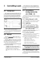
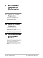
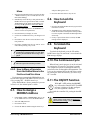
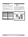
026-1203 Rev 0 09-FEB-2011 XR35CX Digital Controller for Medium Temperature Refrigeration Applications Installation and Operation Manual Retail Solutions 3240 Town Point Drive NW Suite 100 Kennesaw, GA 30144 Phone: 770-425-2724 Fax: 770-425-9319 ALL RIGHTS RESERVED. The information contained in this manual has been carefully checked and is believed to be accurate. However, Computer Process Controls, Inc. assumes no responsibility for any inaccuracies that may be contained herein. In no event will Computer Process Controls, Inc. be liable for any direct, indirect, special, incidental, or consequential damages resulting from any defect or omission in this manual, even if advised of the possibility of such damages. In the interest of continued product development, Computer Process Controls, Inc. reserves the right to make improvements to this manual, and the products described herein, at any time without notice or obligation. Table of Contents 1 INTRODUCTION.......................................................................................................................................................... 1 1.1. GENERAL WARNING ..................................................................................................................................................... 1 2 OVERVIEW ................................................................................................................................................................... 1 2.1. GENERAL DESCRIPTION ................................................................................................................................................ 1 2.2. ORDERING CODE ......................................................................................................................................................... 1 3 CONTROLLING LOADS ............................................................................................................................................ 2 3.1. COMPRESSOR ................................................................................................................................................................ 3.2. DEFROST ....................................................................................................................................................................... 3.3. SECOND RELAY CONFIGURATION (PAR. OA1; TERM. 1-7) ....................................................................................... 3.3.1. Defrost Relay (oA1 = dEF)................................................................................................................................... 3.3.2. Light Relay ............................................................................................................................................................ 3.3.3. Auxiliary Relay (oA1 = AUS)................................................................................................................................ 2 2 2 2 2 2 3.3.3.1. Relay Activation by Digital Input (oA1 = AUS, i2F = AUS) ............................................................................................ 2 3.3.3.2. Auxiliary Thermostat .......................................................................................................................................................... 2 3.3.4. 3.3.5. 3.3.6. 3.3.7. ON/OFF Relay (oA1 = onF)................................................................................................................................. Neutral Zone Regulation....................................................................................................................................... Alarm Relay........................................................................................................................................................... Night Blind Management during Energy Saving Cycles ...................................................................................... 2 3 3 3 4 FRONT PANEL COMMANDS.................................................................................................................................... 4 4.1. KEYS AND FUNCTIONS ................................................................................................................................................. 4 4.2. USE OF LEDS ............................................................................................................................................................... 4 5 MAX AND MIN TEMPERATURE MEMORIZATION........................................................................................... 5 5.1. HOW TO SEE THE MIN TEMPERATURE ........................................................................................................................ 5 5.2. HOW TO SEE THE MAX TEMPERATURE ....................................................................................................................... 5 5.3. HOW TO RESET MAX AND MIN TEMPERATURE RECORDED ...................................................................................... 5 6 MAIN FUNCTIONS ...................................................................................................................................................... 6 6.1. TO SET THE CURRENT TIME AND DAY (ONLY FOR CONTROLLERS WITH RTC) ......................................................... 6.2. HOW TO SEE THE SETPOINT ......................................................................................................................................... 6.3. HOW TO CHANGE THE SETPOINT.................................................................................................................................. 6.4. HOW TO START A MANUAL DEFROST .......................................................................................................................... 6.5. HOW TO CHANGE A PARAMETER VALUE ..................................................................................................................... 6.6. THE HIDDEN MENU ...................................................................................................................................................... 6.6.1. How to Enter the Hidden Menu ............................................................................................................................ 6.6.2. How to Move a Parameter from the Hidden Menu to the First Level and Vice Versa......................................... 6.7. HOW TO ASSIGN A MODBUS ADDRESS ..................................................................................................................... 6.8. HOW TO LOCK THE KEYBOARD ................................................................................................................................... 6.9. TO UNLOCK THE KEYBOARD ....................................................................................................................................... 6.10. THE CONTINUOUS CYCLE........................................................................................................................................... 6.11. THE ON/OFF FUNCTION ............................................................................................................................................ 6 6 6 6 6 6 6 7 7 7 7 7 7 7 PARAMETERS.............................................................................................................................................................. 8 8 DIGITAL INPUTS....................................................................................................................................................... 14 8.1. GENERIC ALARM (I2F=EAL) ..................................................................................................................................... 14 Table of Contents • v 8.2. SERIOUS ALARM MODE (I2F=BAL) ........................................................................................................................... 14 8.3. PRESSURE SWITCH (I2F=PAL) ................................................................................................................................... 14 8.4. DOOR SWITCH INPUT (I1F OR I2F=DOR) .................................................................................................................... 14 8.5. START DEFROST (I1F OR I2F=DEF)............................................................................................................................ 14 8.6. SWITCH THE AUXILIARY RELAY (I2F=AUS) ............................................................................................................. 14 8.7. INVERSION OF THE KIND OF ACTION: HEATING-COOLING (I2F=HTR) ...................................................................... 14 8.8. ENERGY SAVING (I2F=ES) ......................................................................................................................................... 14 8.9. HOLIDAY DEFROST (I2F=HDF) - ONLY FOR MODELS WITH RTC ............................................................................. 14 8.10. ON/OFF FUNCTION (I2F=ONF) ................................................................................................................................ 15 8.11. DIGITAL INPUTS POLARITY ....................................................................................................................................... 15 9 RS485 SERIAL LINE (FOR MONITORING SYSTEMS)...................................................................................... 16 10 X-REP OUTPUT (OPTIONAL) ............................................................................................................................... 16 11 INSTALLATION AND MOUNTING...................................................................................................................... 17 12 ELECTRICAL CONNECTIONS............................................................................................................................. 17 12.1. PROBE CONNECTION ................................................................................................................................................. 17 13 HOW TO USE THE HOT KEY ............................................................................................................................... 18 13.1. HOW TO PROGRAM A HOT KEY FROM THE CONTROLLER (UPLOAD)...................................................................... 18 13.2. HOW TO PROGRAM THE CONTROLLER USING A HOT KEY (DOWNLOAD) ............................................................... 18 14 ALARM SIGNALS .................................................................................................................................................... 19 14.1. SILENCING BUZZER / ALARM RELAY OUTPUT ......................................................................................................... 19 14.2. ALARM RECOVERY ................................................................................................................................................... 19 14.3. OTHER MESSAGES .................................................................................................................................................... 19 15 SPECIFICATIONS.................................................................................................................................................... 20 16 CONNECTIONS ........................................................................................................................................................ 21 17 E2 MODBUS NETWORK WIRING ....................................................................................................................... 22 18 ECT MODBUS NETWORKING TO E2S............................................................................................................... 23 18.1. E2 SETUP OF DEVICES .............................................................................................................................................. 23 18.1.1. Set Up Network Ports........................................................................................................................................ 23 18.1.2. Add and Connect the Device ............................................................................................................................. 24 18.2. WIRING TYPES .......................................................................................................................................................... 26 18.3. MODBUS TERMINATION BLOCKS ........................................................................................................................... 26 19 DEFAULT SETTING VALUES............................................................................................................................... 27 vi • XR35CX I&O Manual 026-1203 Rev 0 09-FEB-2011 1 Introduction 2 Overview 1.1. General Warning 2.1. General Description Please read the following safety precautions and warnings before using this manual: Model XR35CX (32 mm x 74 mm) is a digital thermostat with off-cycle defrost, designed for refrigeration applications at normal temperature. It has two (2) relay outputs to control compressor and light (configurable). It can have a Real Time Clock (RTC) that allows programming of up to six (6) daily defrost cycles, divided into holidays and workdays. A “Day and Night” function with two different setpoints is fitted for energy savings. It can also have up to four (4) NTC or PT1000 probe inputs: the first one for temperature control, the second one located on the evaporator to control the defrost termination temperature. One of the two digital inputs can operate as a third temperature probe. The fourth probe is used to signal the condenser temperature alarm or to display a temperature value. The RS485 serial output enables the controller to be connected to a network line that is a MODBUSRTU compatible, such as the monitoring units of XWEB family. The Hot Key receptacle allows the controller to be programmed by means of the Hot Key programming keyboard. The controller is fully configurable through special parameters that can be easily programmed through the keyboard. CAUTION! • This manual is part of the product and should be kept near the controller for easy and quick reference. • The controller should not be used for purposes different from those described in this manual. It cannot be used as a safety device. • Check the application limits before proceeding. SAFETY PRECAUTIONS AND WARNINGS! • Check that the supply voltage is correct before connecting the controller. • Do not expose to water or moisture: use the controller only within the operating limits and avoid sudden temperature changes with high atmospheric humidity to prevent condensation from forming. • Warning! Disconnect all electrical connections before performing any kind of maintenance. • Fit the probe where it is not accessible by the end user. The controller must not be opened. 2.2. Ordering Code • In case of failure or faulty operation, send the controller back to the distributor or to Retail Solutions (see address) with a detailed description of the fault. Device Name Dixell Code Emerson Code • Verify the maximum current that can be applied to each relay (see Section 15, Specifications). XR35CX 110VAC 318-6020 • Ensure that the wires for probes, loads, and the power supply are separated and far enough from each other, without crossing or intertwining. XR35CX -4C6F3B X0LG1MEUB4NA000 XR35CX 230VAC XR35CX -5C6F3B X0LG1MEUB5NA000 318-6021 • In case of applications in industrial environments, the use of main filters (our mod. FT1) in parallel with inductive loads could be useful. General Warning Table 2-1 - Product Ordering Code Introduction • 1 3 Controlling Loads 3.1. Compressor The regulation is performed according to the temperature measured by the thermostat probe with a positive differential from the setpoint: if the temperature increases and reaches setpoint plus the differential, the compressor is started and then turned OFF when the temperature reaches the setpoint value again. Other parameters are used to control defrost cycles: its maximum defrost duration (MdF) and two defrost modes: time or controlled by the evaporator’s probe (P2P). 3.3. Second Relay Configuration (PAR. oA1; TERM. 1-7) Depending on the kind of application, the function of the second relay (terminals 1-7) can be set through the oA1 parameter. 3.3.1. Defrost Relay (oA1 = dEF) With oA1 = dEF, the relay functions as a defrost relay. See Section 3.2., Defrost for more details. 3.3.2. Light Relay With oA1 = Lig, the relay operates as light. 3.3.3. Auxiliary Relay (oA1 = AUS) Figure 3-1 - Compressor Temperature Regulation In case of a fault in the thermostat probe, the start and stop of the compressor are timed through parameters Con and CoF. 3.2. Defrost With oA1 different from dEF and tdF = EL, the controller performs a timed defrost, simply stopping the compressor. With oA1 = dEF, two defrost modes are available through the tdF parameter: defrost through electrical heater (tdF = EL) and hot gas defrost (tdF = in); in this case, the second relay has to be set. The defrost interval depends on the presence of the RTC (optional). If the RTC is present, it is controlled by means of parameter EdF: • With EdF = in, the defrost is made every IdF time – standard way for controller without RTC. • With EdF = rtC, the defrost is made in real time depending on the hours set in the parameters Ld1...Ld6 on workdays and in Sd1…Sd6 in holidays. 3.3.3.1. Relay Activation by Digital Input (oA1 = AUS, i2F = AUS) With oA1 = AUS and i2F = AUS, the relay 1-7 is switched ON and OFF by a digital input. 3.3.3.2. Auxiliary Thermostat An anti-condensing heater with the possibility of switching it ON and OFF also by keyboard. The function of the auxiliary relay can be configured by means of the following parameters: • ACH - Kind of regulation for the auxiliary relay: Ht: heating; CL: cooling • SAA - Setpoint for auxiliary relay • SHy - Differential for auxiliary relay • ArP - Probe for auxiliary relay • Sdd - Auxiliary output OFF during defrost NOTE: Set oA1 = AUS and ArP = nP (no probe for auxiliary output). In this case the relay 1-7 can be activated only by digital input with i1F or i2F = AUS. 3.3.4. ON/OFF Relay (oA1 = onF) In this case, the relay is activated when the controller is turned ON and deactivated when the controller is turned OFF. 2 • XR35CX I&O Manual 026-1203 Rev 0 09-FEB-2011 3.3.5. Neutral Zone Regulation With oA1 = db, relay 1-7 can control a heater element to perform a neutral zone action. • oA1 cut in = SEt - Hy • oA1 cut out = SEt 3.3.6. Alarm Relay With oA1 = ALr, the relay 1-7 operates as an alarm relay. It is activated every time an alarm occurs. Its status depends on the tbA parameter: if tbA = y, the relay is silenced by pressing any key. If tbA = n, the alarm relay remains ON until the alarm condition recovers. 3.3.7. Night Blind Management during Energy Saving Cycles With oA1 = HES, the relay 1-7 operates to manage the night blind: the relay is energized when the energy saving cycle is activated, by digital input, frontal button or RTC (optional). Second Relay Configuration (PAR. oA1; TERM. 1-7) Controlling Loads • 3 4 Front Panel Commands Switches the light ON and OFF, if oA1 = Lig. Key Combinations To lock and unlock the keyboard. To enter programming mode. To return to the room temperature display. Table 4-1 - XR35CX Front Panel Keys and Functions 4.2. Use of LEDS Each LED function is described in Table 4-2: Figure 4-1 - XR35CX Front Panel LED Mode Function ON Compressor enabled Flashing Anti-short cycle delay enabled ON Defrost enabled Flashing Drip time in progress ON An alarm is occurring ON Continuous cycle is running ON Energy saving enabled ON Light ON (UP arrow key) To see the MAX stored temperature; in programming mode, it browses the parameter codes or increases the displayed value. ON Auxiliary relay ON ON Measurement unit (DOWN arrow key) To see the MIN stored temperature; in programming mode, it browses the parameter codes or decreases the displayed value. Flashing Programming phase 4.1. Keys and Functions Table 4-1 shows the keys that are found on the front panel of the XR35CX controller and their corresponding functions: Key Function To display the target setpoint; in programming mode, it selects a parameter or confirms an operation. (DEF key) To start a manual defrost. Table 4-2 - LEDs Switches the controller OFF, if onF = oFF. Table 4-1 - XR35CX Front Panel Keys and Functions 4 • XR35CX I&O Manual 026-1203 Rev 0 09-FEB-2011 5 MAX and MIN Temperature Memorization 5.1. How to See the MIN Temperature 1. Press and release the DOWN arrow key. 2. The Lo message will be displayed followed by the minimum temperature recorded. 3. By pressing the DOWN arrow key again or by waiting 5 seconds, the normal display will be restored. 5.2. How to See the MAX Temperature 1. Press and release the UP arrow key. 2. The Hi message will be displayed followed by the maximum temperature recorded. 3. By pressing the UP arrow key again or by waiting 5 seconds, the normal display will be restored. 5.3. How to Reset MAX and MIN Temperature Recorded 1. Press and hold the SET key for more than 3 seconds while the maximum or minimum temperature is displayed. (rSt message will be displayed) 2. To confirm the operation, the rSt message starts blinking and the normal temperature will be displayed. How to See the MIN Temperature MAX and MIN Temperature Memorization • 5 6 Main Functions the setpoint value. 2. The value of the setpoint will be displayed and the °C or °F LED starts blinking. 3. To change the setpoint value, push the UP or DOWN arrow keys within 10 seconds. 6.1. To Set the Current Time and Day (Only for Controllers with RTC) When the controller is switched ON, it is necessary to program the time and day. 1. Enter the Pr1 programming menu by pressing the SET + DOWN arrow keys combination for 3 seconds. 2. The rtc parameter displays. Press the SET key to enter the real time clock menu. 4. To memorize the new setpoint value, push the SET key again or wait 10 seconds. 6.4. How to Start a Manual Defrost Push the DEF key for more than 2 seconds and a manual defrost will start. 3. The Hur (hour) parameter displays. 4. Press the SET key and set current hour by pressing the UP and DOWN arrow keys, then press SET to confirm the value. 5. Repeat the steps on Min (minutes) and dAy (day) parameters. 6. To exit, press SET + UP arrow keys or wait for 15 seconds. NOTE: This function setup is applicable only for controllers with RTC. 6.2. How to See the Setpoint 1.Push and immediately release the SET key: the display will show the setpoint value. 6.5. How to Change a Parameter Value To change the parameter’s value operate as follows: 1. Enter the Programming mode by pressing the SET + DOWN arrow keys for 3 seconds (the °C or °F LED starts blinking). 2. Select the required parameter (refer to Section 7, Parameters for the list of parameters). Press the SET key to display its value. 3. Use the UP or DOWN arrow keys to change its value. 4. Press SET to store the new value and move to the following parameter. 5. To exit, press SET + UP arrow keys or wait 15 seconds without pressing a key. NOTE: The set value is stored even when the time-out expires and ends the procedure. 2.Push and immediately release the SET key or wait for 5 seconds to display the probe value again. 6.3. How to Change the Setpoint 1. Push the SET key for more than 2 seconds to change 6 • XR35CX I&O Manual 6.6. The Hidden Menu The Hidden Menu includes all the parameters of the controller. 6.6.1. How to Enter the Hidden 026-1203 Rev 0 09-FEB-2011 Menu 1. Enter the Programming mode by pressing the SET + DOWN arrow keys for 3 seconds (the °C or °F LED starts blinking). 2. Immediately release the keys, then push the SET + DOWN arrow keys again for more than 7 seconds. The Pr2 label will be displayed immediately followed by the Hy parameter. NOW YOU ARE IN THE HIDDEN MENU. 3. Select the required parameter. See Section 7, Parameters for the list of parameters. 4. Press the SET key to display its value. 5. Use the UP or DOWN arrow keys to change its value. 6. Press SET to store the new value and move to the next parameter. 7. Press SET + DOWN arrow keys or wait for 15 seconds without pressing a key to exit. NOTE: If a parameter is not present in Pr1, the noP message is displayed after 3 seconds. Keep the keys pressed until the Pr2 message is displayed. NOTE: The set value is stored even when the time-out expires and ends the procedure. 6.6.2. How to Move a Parameter from the Hidden Menu to the First Level and Vice Versa Each parameter present in the Hidden Menu can be removed or put into THE FIRST LEVEL (user level) by pressing SET + DOWN arrow keys. In the Hidden Menu, when a parameter is present in First Level, the decimal point is visible. 6.7. How to Assign a MODBUS Address 1. Follow Steps 1 and 2 of Section 6.6.1., How to Enter the Hidden Menu to access the Hidden Menu. 2. Select the Adr parameter. 3. Press SET to select. and press SET again to save. 5. Press the SET and UP arrow keys to exit. 6.8. How to Lock the Keyboard 1. Keep the UP and the DOWN arrow keys pressed for more than 3 seconds. 2. The PoF message will be displayed and the keyboard will be locked. At this point it will be possible to see the setpoint or the MAX or MIN temperature stored only. 3. If a key is pressed more than 3 seconds, the PoF message will be displayed. 6.9. To Unlock the Keyboard To unlock the keyboard, press the UP and the DOWN arrow keys for more than 3 seconds until the Pon message displays. 6.10. The Continuous Cycle When defrost is not in progress, it can be activated by pressing the UP arrow key for about 3 seconds. The compressor operates to maintain the CCS setpoint for the time set through the CCt parameter. The cycle can be terminated before the end of the set time by pressing the same activation key (UP arrow key) for 3 seconds. 6.11. The ON/OFF Function With onF = oFF, pushing the ON/OFF key will turn the controller OFF. The OFF message is displayed. In this configuration, the regulation is disabled. To switch the controller ON, push again the ON/ OFF key. WARNING! Loads connected to the normally closed contacts of the relays are always supplied and under voltage, even if the controller is in stand-by mode. 4. Choose the address number using the arrow keys How to Assign a MODBUS Address Main Functions • 7 7 Parameters Code rtc Parameter Function Real time clock menu (only for controller with RTC) Sets the time and date and the defrost start time. REGULATION Hy Differential (0.1 to 25.5°C / 1 to 255°F) Intervention differential for setpoint. Compressor Cut IN is Setpoint + differential (Hy). Compressor Cut OUT is when the temperature reaches the setpoint. LS Minimum setpoint (-100°C to SEt/-148°F to SEt) Sets the minimum value for the setpoint. US Maximum setpoint (SEt to 110°C/ SEt to 230°F) Sets the maximum value for the setpoint. ot Thermostat probe calibration (-12.0 to 12.0°C; -120 to 120°F) Allows to adjust possible offset of the thermostat probe. P2P Evaporator probe presence n = not present: the defrost stops by time y = present: the defrost stops by temperature oE Evaporator probe calibration (-12.0 to 12.0°C; -120 to 120°F) Allows to adjust possible offset of the evaporator probe. P3P Third probe presence (P3) n = not present: the terminals 18-20 operate as digital input y = present: the terminals 18-20 operate as third probe o3 Third probe calibration (P3) (-12.0 to 12.0°C; -120 to 120°F) Allows to adjust possible offset of the third probe. P4P Fourth probe presence (n = not present, y = present) o4 Fourth probe calibration (-12.0 to 12.0°C) Allows to adjust possible offset of the fourth probe. Ods Outputs activation delay at start up (0 to 255 min) This function is enabled at the initial start up of the controller and inhibits any output activation for the period of time set in the parameter. Ac Anti-short cycle delay (0 to 50 min) Minimum interval between the compressor stop and the following restart. rtr Percentage of the second and first probe for regulation (0 to 100; 100 = P1, 0 = P2) Allows to set the regulation according to the percentage of the first and second probe, as for the following formula (rtr(P1 - P2)/ 100 + P2). CCt Compressor ON time during continuous cycle (0.0 to 24.0 hr, res. 10 min) Allows to set the length of the continuous cycle: compressor stays ON without interruption for the CCt time. Can be used, for instance, when the room is filled with new products. CCS Setpoint for continuous cycle (-100 to 150°C) Sets the setpoint used during the continuous cycle. Con Compressor ON time with faulty probe (0 to 255 min) Time during which the compressor is active in case of faulty thermostat probe. With Con = 0, compressor is always OFF. Table 7-1 - List of Parameters 8 • XR35CX I&O Manual 026-1203 Rev 0 09-FEB-2011 Code Parameter Function CoF Compressor OFF time with faulty probe (0 to 255 min) Time during which the compressor is OFF in case of faulty thermostat probe. With CoF = 0, compressor is always active. CH Type of action CL = cooling; Ht = heating DISPLAY CF Temperature measurement unit °C = Celsius; °F = Fahrenheit CAUTION! When the measurement unit is changed, the setpoint and the values of the parameters Hy, LS, US, ot, ALU, and ALL have to be checked and modified if necessary. rES Resolution (for °C) (in = 1°C; dE = 0.1°C) Allows decimal point display. Lod Controller display (P1, P2, P3, P4, SEt, dtr) Selects which probe is displayed by the controller: P1 = Thermostat probe P2 = Evaporator probe P3 = Third probe (only for model with this option enabled) P4 = Fourth probe SEt = setpoint dtr = percentage of visualization Red X- REP display (optional) (P1, P2, P3, P4, SEt, dtr) Selects which probe is displayed by X-REP: P1 = Thermostat probe P2 = Evaporator probe P3 = Third probe (only for model with this option enabled) P4 = Fourth probe SEt = setpoint dtr = percentage of visualization dLy Display delay (0 to 20.0 min, res. 10 sec) When the temperature increases, the display is updated of 1°C/ 1°F after this time. dtr Percentage of the second and first probe for visualization when Lod = dtr (0 to 100; 100 = P1, 0 = P2) if Lod = dtr: Allows to set the visualization according to the percentage of the first and second probe, as for the following formula (dtr(P1 P2)/100 + P2). DEFROST EdF Defrost mode (only for controller with RTC) rtC = Real Time Clock mode: Defrost time follows Ld1 to Ld6 parameters on workdays and Sd1 to Sd6 on holidays. in = Interval mode: The defrost starts when the time Idf is expired. tdF Defrost type EL = electric heater; in = hot gas dFP Probe selection for defrost termination nP = no probe P1 = thermostat probe P2 = evaporator probe P3 = configurable probe P4 = probe on Hot Key plug dtE Defrost termination temperature (-50 to 50°C/ -58 to 122°F) (Enabled only when EdF = Pb) Sets the temperature measured by the evaporator probe, which causes the end of defrost. Table 7-1 - List of Parameters The ON/OFF Function Parameters • 9 Code Parameter Function IdF Interval between defrost cycles (0 to 120 hr) Determines the time interval between the beginning of two defrost cycles. MdF Maximum duration for defrost (0 to 255 min) When P2P = n, (not evaporator probe: timed defrost), it sets the defrost duration. When P2P = y (defrost end based on temperature), it sets the maximum duration for defrost. dSd Start defrost delay (0 to 99 min) This is useful when different defrost start times are necessary to avoid overloading the plant. dFd Temperature displayed during defrost (rt = real temperature; it = temperature at defrost start; SEt = setpoint; dEF = dEF label) dAd MAX display delay after defrost (0 to 255 min) Sets the maximum time between the end of defrost and the restarting of the real room temperature display. Fdt Drip time (0 to 120 min) Time interval between reaching defrost termination temperature and the restoring of the controller’s normal operation. This time allows the evaporator to eliminate water drops that might have formed due to defrost. dPo First defrost after start-up (y = immediate; n = after the IdF time) dAF Defrost delay after continuous cycle (0 to 23.5 hr) Time interval between the end of the fast freezing cycle and the following defrost related to it. AUXILIARY THERMOSTAT CONFIGURATION (terms. 1-7) - oA1 = AUS ACH Kind of regulation for auxiliary relay Ht = heating; CL = cooling SAA Setpoint for auxiliary relay (-100 to 110.0°C; -148 to 230°F) Defines the room temperature setpoint to switch auxiliary relay. SHy Differential for auxiliary output (0.1 to 25.5°C / 1 to 255°F) Intervention differential for auxiliary output setpoint. With ACH = CL, AUX Cut in is SAA + SHy; AUX Cut out is SAA. With ACH = Ht, AUX Cut in is SAA - SHy; AUX Cut out is SAA. ArP Probe selection for auxiliary nP = no probe, the auxiliary relay is switched only by the digital input P1 = Probe 1 (thermostat probe) P2 = Probe 2 (evaporator probe) P3 = Probe 3 (display probe) P4 = Probe 4 Sdd Auxiliary relay OFF during defrost n = the auxiliary relay operates during defrost; y = the auxiliary relay is switched OFF during defrost ALARMS ALP Probe selection for alarm nP = no probe, the temperature alarms are disabled P1 = Probe 1 (Thermostat probe) P2 = Probe 2 (evaporator probe) P3 = Probe 3 (display probe) P4 = Fourth probe Table 7-1 - List of Parameters 10 • XR35CX I&O Manual 026-1203 Rev 0 09-FEB-2011 Code Parameter Function ALC Temperature alarms configuration (Ab; rE) Ab = Absolute temperature: alarm temperature is given by the ALL or ALU values; rE = Temperature alarms are referred to the setpoint. Temperature alarm is enabled when the temperature exceeds the SEt + ALU or SEt- ALL values. ALU MAXIMUM temperature alarm (ALL to 110°C; ALL to 230°F) When this temperature is reached, the alarm is enabled after the ALd delay time. ALL Minimum temperature alarm (-100°C to ALU; -148 to ALU) When this temperature is reached, the alarm is enabled after the ALd delay time. AFH Differential for temperature alarm recovery (0.1 to 25.5°C; 1 to 45°F) Intervention differential for recovery of temperature alarm. ALd Temperature alarm delay (0 to 255 min) Time interval between the detection of an alarm condition and alarm signaling. dAo Exclusion of temperature alarm at startup (from 0.0 min to 23.5 hr) Time interval between the detection of the temperature alarm condition after controller power ON and alarm signaling. CONDENSER TEMPERATURE ALARM AP2 Probe selection for temperature alarm of condenser nP = no probe P1 = thermostat probe P2 = evaporator probe P3 = configurable probe P4 = probe on Hot Key plug AL2 Low temperature alarm of condenser (-100 to 150°C; -148 to 302°F) When this temperature is reached the LA2 alarm is signaled, possibly after the Ad2 delay. AU2 High temperature alarm of condenser (-100 to 150°C; -148 to 302°F) When this temperature is reached the HA2 alarm is signaled, possibly after the Ad2 delay. AH2 Differential for temperature condenser alarm recovery (0.1 to 25.5°C; 1 to 45°F) Ad2 Condenser temperature alarm delay (0 to 255 min) Time interval between the detection of the condenser alarm condition and alarm signaling. dA2 Condenser temperature alarm exclusion at start up (from 0.0 min to 23.5 hr, res. 10 min) bLL Compressor OFF with low temperature alarm of condenser n = no: compressor keeps on working Y = yes: compressor is switched OFF until the alarm is present, in any case regulation restarts after Ac time at minimum AC2 Compressor OFF with high temperature alarm of condenser n = no: compressor keeps on working Y = yes: compressor is switched OFF till the alarm is present, in any case regulation restarts after Ac time at minimum AUXILIARY RELAY tbA Alarm relay silencing (with oA1 = ALr) n = silencing disabled: alarm relay stays ON until alarm condition lasts y = silencing enabled: alarm relay is switched OFF by pressing a key during an alarm Table 7-1 - List of Parameters The ON/OFF Function Parameters • 11 Code Parameter Function oA1 Second relay configuration (1-7) dEF = defrost; FAn: do not select it!; ALr: alarm; Lig: light; AUS: Auxiliary relay; onF: always ON with controller ON; db = neutral zone; cP2 = do not select it!; dEF2: do not select it!; HES: night blind AOP Alarm relay polarity Set if the alarm relay is open or closed when an alarm happens. CL = terminals 1-7 closed during an alarm oP = terminals 1-7 open during an alarm DIGITAL INPUTS i1P Digital input polarity (18-20) oP = the digital input is activated by opening the contact CL = the digital input is activated by closing the contact i1F Digital input configuration (18-20) dor = door switch function dEF = activation of a defrost cycle i2P 2nd digital input polarity (18-19) oP = the digital input is activated by opening the contact CL = the digital input is activated by closing the contact i2F 2nd digital input configuration (18-19) EAL = external alarm: EA message is displayed; bAL = serious alarm; CA message is displayed; PAL = pressure switch alarm, CA message is displayed; dor = door switch function; dEF = activation of a defrost cycle; ES = energy saving; AUS = auxiliary relay activation with oA1 = AUS; Htr = kind of action inversion (cooling – heating); FAn = fan; HdF = Holiday defrost (enable only with RTC); onF = to switch the controller OFF did With i2F = EAL or i2F = bAL: digital input alarm delay (18-20) (0 to 255 min) Delay between the detection of the external alarm condition and its signaling. With i2F = PAL: time for pressure switch function (0 to 255 min) Time interval to calculate the number of the pressure switch activation. doA Door open signaling delay (0 to 255 min) nPS Pressure switch number (0 to 15) Number of activation of the pressure switch, during the did interval, before signaling the alarm event (i2F= PAL). If the nPS activation in the did time is reached, switch OFF and ON the controller to restart normal regulation. Odc Compressor status when open door no; FAn = normal; CPr, F_C = Compressor OFF rrd Outputs restart after doA alarm no = outputs not affected by the doA alarm yES = outputs restart with the doA alarm HES Temperature increase during the Energy Saving cycle (-30.0°C to 30.0°C) Sets the increasing value of the setpoint during the Energy Saving cycle. TO SET CURRENT TIME AND WEEKLY HOLIDAYS (ONLY FOR MODELS WITH RTC) Hur Current hour (0 to 23 hr) Sets the current hour. Min Current minute (0 to 59 min) Sets the current minute. dAY Current day (Sun to SAt) Sets the current day of the week. Hd1 First weekly holiday (Sun to not used) Sets the first day of the week which follows the holiday times. NOTE: Hd1 can be set also as not used value. Hd2 Second weekly holiday (Sun to not used) Sets the second day of the week which follows the holiday times. NOTE: Hd2 can be set also as not used value. Table 7-1 - List of Parameters 12 • XR35CX I&O Manual 026-1203 Rev 0 09-FEB-2011 Code Parameter Function TO SET ENERGY SAVING TIMES (ONLY FOR MODELS WITH RTC) iLE Energy Saving cycle start during workdays (0 to 23 hr 50 min) During the Energy Saving cycle, the setpoint is increased by the value in HES so that the operation setpoint is SEt + HES. dLE Energy Saving cycle length during workdays (0 to 24 hr 00 min) Sets the duration of the Energy Saving cycle on workdays. iSE Energy Saving cycle start on holidays. (0 to 23 hr 50 min) dSE Energy Saving cycle length on holidays (0 to 24 hr 00 min) TO SET DEFROST TIMES (ONLY FOR MODELS WITH RTC) Ld1 to Ld6 Workday defrost start (0 to 23 hr 50 min) These parameters set the beginning of the 6 programmable defrost cycles during workdays. (e.g., When Ld2 = 12.4 the second defrost starts at 12:40 during workdays.) Sd1 to Sd6 Holiday defrost start (0 to 23 hr 50 min) These parameters set the beginning of the 6 programmable defrost cycles on holidays. (e.g., When Sd2 = 3.4 the second defrost starts at 3:40 on holidays.) NOTE: To disable a defrost cycle, set it to not used. (e.g., If Ld6 = not used, the sixth defrost cycle is disabled.) OTHER PARAMETERS Adr Serial address (1 to 244) Identifies the controller address when connected to a MODBUS compatible monitoring system. pbC Type of probe Allows to set the kind of probe used by the controller: Pt1 = Pt1000 probe ntc = NTC probe onF ON/OFF key enabling not used = disabled oFF = enabled ES = not set it dP1 Thermostat probe display dP2 Evaporator probe display dP3 Third probe display (optional) dP4 Fourth probe display rSE Real setpoint Shows the setpoint used during the energy saving cycle or during the continuous cycle. rEL Software release For internal use only. Ptb Parameter table code Read only Table 7-1 - List of Parameters The ON/OFF Function Parameters • 13 8 Digital Inputs The first digital input 18-20 is enabled with P3P = n. With P3P = n and i1F = i2F, the second digital input is disabled. The free voltage digital inputs are programmable by the i1F and i2F parameters. 8.1. Generic Alarm (i2F=EAL) As soon as the digital input is activated, the unit will wait for the did time delay before signaling the EAL alarm message. The outputs status do not change. The alarm stops just after the digital input is deactivated. 8.2. Serious Alarm Mode (i2F=bAL) When the digital input is activated, the unit will wait for the did delay before signaling the CA alarm message. The relay outputs are switched OFF. The alarm will stop as soon as the digital input is deactivated. 8.3. Pressure Switch (i2F=PAL) If the pressure switch has reached the number of activations (cycles) of the nPS parameter during the interval time set by the did parameter, the CA pressure alarm message will be displayed. The compressor and the regulation are stopped. When the digital input is ON, the compressor is always OFF. If the nPS activation in the did time is reached, switch the controller OFF and ON to restart normal regulation. 8.4. Door Switch Input (i1F or i2F=dor) This input signals the door status and the corresponding relay output status through the Odc parameter: no, Fan = normal (any change); CPr; F_C = Compressor OFF. 14 • XR35CX I&O Manual Since the door is opened, after the delay time set through the parameter doA, the door alarm is enabled, the display shows the message dA and the regulation restarts is rtr = yES. The alarm stops as soon as the external digital input is disabled again. With the door open, the high and low temperature alarms are disabled. 8.5. Start Defrost (i1F or i2F=dEF) If conditions are favorable for defrost, a defrost will be started. After the defrost is finished, the normal regulation will restart only if the digital input is disabled, otherwise the controller will wait until the MdF safety time is expired. 8.6. Switch the Auxiliary Relay (i2F=AUS) With oA1 = AUS, the digital input switches the status of the auxiliary relay. 8.7. Inversion of the Kind of Action: HeatingCooling (i2F=Htr) This function enables the controller to invert the regulation of the controller: from cooling to heating and vice versa. 8.8. Energy Saving (i2F=ES) The Energy Saving function allows you to change the setpoint value as the result of the SEt + HES (parameter) sum. This function is enabled until the digital input is activated. 8.9. Holiday Defrost (i2F=HdF) - Only for Models with RTC This function enables the holiday defrost setting. 026-1203 Rev 0 09-FEB-2011 8.10. ON/OFF Function (i2F=onF) Switches the controller ON and OFF. 8.11. Digital Inputs Polarity The digital input polarity depends on the i1P and i2P parameters. • i1P or i2P = CL: the input is activated by closing the contact. • i1P or i2P = oP: the input is activated by opening the contact. ON/OFF Function (i2F=onF) Digital Inputs • 15 9 RS485 Serial Line (for Monitoring Systems) 10 X-REP Output (Optional) Optionally, an X-REP can be connected to the controller through the dedicated connector. The RS485 serial line allows you to connect the controller to a monitoring system MODBUS-RTU compatible, such as the X-WEB500/3000/300. Figure 10-1 - X-REP Output To connect the X-REP to the controller, the following connectors must be used: CAB-51F(1m), CAB-52F(2m), and CAB-55F(5m). 16 • XR35CX I&O Manual 026-1203 Rev 0 09-FEB-2011 11 Installation and Mounting 12 Electrical Connections The controller comes with a screw terminal block to connect cables with a cross section up to 2.5 mm2. Before connecting cables, verify that the power supply complies with the controller’s requirements. Separate the probe cables from the power supply cables, from the outputs and the power connections. Do not exceed the maximum current allowed on each relay; in case of heavier loads, use a suitable external relay. 12.1. Probe Connection Figure 11-1 - Installation and Mounting of XR35CX The XR35CX controller should be mounted on a vertical panel, in a 29 x 71 mm hole, and secured using the special bracket supplied. The temperature range allowed for correct operation is 0 to 60°C. Avoid places subject to strong vibrations, corrosive gases, excessive dirt, or humidity. The same recommendations apply to probes. Allow air to circulate through the cooling holes. Probe Connection The probes should be mounted with the bulb upwards to prevent damages due to casual liquid infiltration. It is recommended that the thermostat probe be placed away from air streams to measure the average room temperature correctly. Place the defrost termination probe among the evaporator fans in the coldest place, (where most ice is formed) and far from heaters or from the warmest place during defrost, to prevent premature defrost termination. Installation and Mounting • 17 13 How to Use the Hot Key 13.1. How to Program a Hot Key From the Controller (Upload) 1. Program one controller using the front keypad. 2. When the controller is ON, insert the Hot Key and push the UP arrow key; the uPL message appears followed by a flashing End LED. 3. Push the SET key and the End LED will stop flashing. 4. Turn OFF the controller, remove the Hot Key, then turn it ON again. NOTE: The Err message is displayed in case of an error or failure in programming. In this case push the UP arrow key again if you want to restart the upload or remove the Hot Key to abort the operation. 13.2. How to Program the Controller Using a Hot Key (Download) 1. Turn OFF the controller. 2. Insert a programmed Hot Key into the 5-pin receptacle and then turn the Controller ON. 3. Automatically, the parameter list of the Hot Key is downloaded into the controller memory; the doL message will blink followed by a flashing End LED. 4. After 10 seconds, the controller will restart working with the new parameters. 5. Remove the Hot Key. NOTE: The Err message is displayed in case of an error or failure in programming. In this case, turn the unit OFF and then ON if you want to restart the download or remove the Hot Key to abort the operation. 18 • XR35CX I&O Manual 026-1203 Rev 0 09-FEB-2011 14 Alarm Signals Message Cause Outputs P1 Room probe failure Compressor output acc. to par. Con and COF P2 Evaporator probe failure Defrost end is timed P3 Third probe failure Outputs unchanged P4 Fourth probe failure Outputs unchanged HA Maximum temperature alarm Outputs unchanged LA Minimum temperature alarm Outputs unchanged. HA2 Condenser high temperature It depends on the Ac2 parameter LA2 Condenser low temperature It depends on the bLL parameter dA Door open Compressor restarts EA External alarm Output unchanged CA Serious external alarm (i1F = bAL) All outputs OFF CA Pressure switch alarm (i1F = PAL) All outputs OFF rtc Real time clock alarm Alarm output ON; Other outputs unchanged; Defrosts according to par. IdF Set real time clock has to be set Real time clock board failure Alarm output ON; Other outputs unchanged; Defrosts according to par. IdF Contact the service rtF If tbA = n, only the buzzer is silenced while the alarm relay is ON until the alarm condition recovers. 14.2. Alarm Recovery Probe alarms P1, P2, P3, and P4 start some seconds after the fault in the related probe; they automatically stop some seconds after the probe restarts normal operation. Check connections before replacing the probe. Temperature alarms HA, LA, HA2, and LA2 automatically stop as soon as the temperature returns to normal values. Alarms EA and CA (with i1F = bAL) recover as soon as the digital input is disabled. Alarm CA (with i1F = PAL) recovers only by switching the controller OFF and ON. 14.3. Other Messages Message Output Pon Keyboard unlocked PoF Keyboard locked noP In programming mode: No parameter is present in Pr1. On the display or in dP2, dP3, dP4: The selected probe is not enabled. Table 14-2 - Additional Display Messages Table 14-1 - Alarm Signals 14.1. Silencing Buzzer / Alarm Relay Output If tbA = y, the buzzer and the relay are silenced by pressing any key. Silencing Buzzer / Alarm Relay Output Alarm Signals • 19 15 Specifications Housing Self extinguishing ABS Dimensions Case: Front: 32 mm x 74 mm Depth: 60 mm Panel Mount: 71 mm x 29 mm panel cut-out Protection IP 20 Frontal: IP65 Connections Screw terminal block ≤ 2.5 mm2 wiring Power Supply (depending on the model) 24VAC, ±10% 230VAC, ±10%, 50/60Hz 110VAC, ±10%, 50/60Hz Power Absorption 34VA max Display 3 digits, red LED, 14.2 mm high Inputs Relay outputs Up to 4 NTC or PT1000 probes Digital: Free voltage contact Compressor: SPST 8(3) A, 250VAC or SPST 16A 250VAC Aux: SPDT 8(3) A, 250VAC Data Storing On the non-volatile memory (EEPROM) Internal Clock Back-up 24 hours Kind of Action 1B Pollution Grade 2 Software Class A Rated Impulsive Voltage 2500V Overvoltage Category II Temperature Relative Humidity Operating: 0 to 55°C Storage: -30 to 85°C 20 to 85% (no condensing) NTC probe: -40 to 110°C (-40 to 230°F) Measuring and Regulation Range PT1000 probe: -100 to 150°C (-148 to 302°F) Resolution 0.1°C or 1°C or 1 °F (selectable) Accuracy (ambient temp. 25°C) ±0.7°C ±1 digit Table 15-1 - XR35CX Specifications 20 • XR35CX I&O Manual 026-1203 Rev 0 09-FEB-2011 16 Connections Figure 16-1 - XR35CX Connections • Supply: 120VAC or 24 VAC: connect to terminals 5-6. • The X-REP output is optional. Other Messages Connections • 21 17 E2 MODBUS Network Wiring • Connect the MODBUS Network to the RS485 Connector on the E2 PIB board (Belden 8641 recommended). • Note to wire the RS485 +/- polarity at the E2 in the reverse of the XR35CX devices. • Position the three termination jumpers to the UP (terminated) position to provide RS485 termination at the E2. • Do not connect the shield of the MODBUS network to the E2 PIB center terminal. Instead, use a 100 ohm 1/2 watt resistor to connect the MODBUS cable shield to earth ground. • At each XR35CX device, wire the MODBUS cable to the RS485 +/- terminals and connect the MODBUS shield to the pin 18 terminal. • Terminate the end of the MODBUS network at the last XR35CX device on the daisy chain with the MODBUS termination block (P/N 535-2711), or by connecting a 150 ohm resistor between the MODBUS +/- terminals. EARTH GROUND CONNECTION 100 ohm ½ Watt MODBUS TERMINATION BLOCK 535-2711 150 ohm Terminate last device only Shield Shield Shield REVERSE POLARITY OF +/- ON RS-485 CABLE FROM E2 TO DEVICE Figure 17-1 - XR35CX to E2 MODBUS Network Wiring 22 • XR35CX I&O Manual 026-1203 Rev 0 09-FEB-2011 18 ECT MODBUS Networking to E2s Connect the MODBUS network cable to the threeterminal connector on the COM port you wish to assign as MODBUS. Reverse polarity of +/- on RS485 cable from E2 to the device. E2 PIB COM PORT ASSOCIATIONS E2 Enclosure (Right Side) Connecting a XR35CX controller to an E2 requires the E2 to be version 2.84 or above. Contact Retail Solutions for upgrade information if the controller is a version before 2.84. An E2 has up to three COM ports that can be assigned for MODBUS communication: COM2, an RS485 port on the E2 power interface board, and COM4 and COM6, which are optional ports requiring expansion cards. COM4 is recommended for MODBUS connection of XR35CX units. COM ports can only be used for one function; in other words, if COM2 is set up as the I/O network, you cannot connect MODBUS devices to COM2. Ensure your E2 is equipped with an RS485 COM Card (P/N 637-4890) and configured in E2 General Services (, Serial tab) to enable COM4 or an E2 Expansion COM Card (P/N 637-4871) to enable COM6. E2 Modem/Expansion COM Card Mounted Above PIB RS232 COM3 Plug-In Modem Card COM6 COM1 RS485 RS485 COM Card (2 Connectors) COM4 COM2 Serial Device RS232 Port POWER INTERFACE BOARD (PIB) Serial Device RS485 COM Port (2 Connectors) Figure 18-1 - Location of E2 COM Ports TERMINATED, BIASED (ALL 3 JUMPERS IN UP POSITION) E2 XR75CX XR35CX XR35CX XR35CX #1 #2 #3 #1 Figure 18-2 - MODBUS Networking 18.1. E2 Setup of Devices 18.1.1.Set Up Network Ports Before setting up a device, the port on the E2 that has the MODBUS cable connected must be set up as a MODBUS port. 1. Log in to the E2 with Level 4 access. 2. Press followed by - General Controller Info. E2 Setup of Devices ECT MODBUS Networking to E2s • 23 3. Press + to open the Serial tab of the General Controller Info setup screens: and Controllers. Figure 18-4 - Num Network Ctrls: NetSetup Screen Figure 18-3 - Serial Communications Manager Screen 4. This screen will have a “Connection” field for all COM ports on the E2. Highlight the COM port connection field that will be used for the device, and press - LOOK UP. From the list of network types, select MODBUS. 5. Four fields will become visible underneath the COM port connection field, which pertain to the way the device communicates: • Baud - Default setting is 19.2k. The baud rate setting should be set to match the baud rate of the device (9600). (All devices connected to the same COM port should be set to the same baud rate.) 3. In the Num Network Ctrls: NetSetup screen, under the ECT tab, enter the number of devices in the Quantity field. (Max shows the maximum number of devices allowed on the network.) 4. Press to return to the Network Setup menu, then select - Network Summary. 5. Locate the units you added to the network list (press and to scroll through the list). If desired, enter a new name for each device in the Name field. • Data Size - Leave this field at the default value (8). • Parity - Leave this field at the default value (None). • Stop Bits - Leave this field at the default value (1). 6. Press to save changes and exit. 18.1.2.Add and Connect the Device To enable communications between E2 and the XR35CX units, the devices must be added and addressed in E2. 1. Log in to the E2 with Level 4 access. 2. Press - Connected I/O Boards Figure 18-5 - Network Summary Screen 6. By default, each device in the network list has a board number of 0. To set the address and begin communication, choose the device and press . In the list of MODBUS devices, choose the address number corresponding to the XR35CX address set up through the XR35CX front display, and press to select it. A window will open where 24 • XR35CX I&O Manual 026-1203 Rev 0 09-FEB-2011 you can specify the address of the controller. If a network ID has already been selected, its name will be shown next to the network ID in this list. If the network ID you are trying to assign has already been used, you must set the address on this device to a different number that is not being used. that has the latest version of firmware on it. Figure 18-7 - Network Summary Screen Figure 18-6 - List of MODBUS Devices 7. Repeat Steps 5 and 6 until each device has a name and address. 8. When finished, press to return to the Net- work Setup menu, then press - Network Summary (Figure 18-7). Locate the devices you set up, and look at each device’s status in the Status field. You will see one of the following messages: • Online - The device is communicating normally. • Offline - The device is not communicating, has not been commissioned, is not functional, or is not powered up. Verify the device is powered up, wired correctly, and has the proper network address, baud rate, and parity. • Unknown - The device is not communicating or has not been commissioned. Verify the device is powered up, wired correctly, and has the proper network address, baud rate, and parity. • No Port - No port is set up in the E2 Serial Configuration Manager to be a MODBUS port. • Wrong FW Rev - This message is likely caused by the device having a firmware version older than the minimum revision required by E2 for communication. Replace the device with a new one or a device E2 Setup of Devices ECT MODBUS Networking to E2s • 25 18.2. Wiring Types Retail Solutions specifies Belden #8761 shielded twisted pair cables for use as MODBUS wiring (or Belden #82761 and Belden #88761 for plenum installations). For MODBUS network wiring of XR35CX controllers to E2, Belden #8641 (CPC P/N 135-8641) is the recommended wire type to use. If the recommended cable is not available in your area, be sure the wiring meets or exceeds the following specs: Shielded? Yes Conductor Type Twisted Pair Gauge 18 - 24 AWG Capacitance between signal wires 31 pF/ft or less (9.45 m) or less Capacitance between signal and shield 59 pF/ft or less (17.98 m) or less Maximum Length 4000 ft/18 to 22 AWG (1219.2 m) 2500 ft/24 AWG (762 m) Nominal Impedance 120±50 18.3. MODBUS Termination Blocks Because the XR35CX device has no on-board means of termination, use the MODBUS termination block (P/N 535-2711) for termination that can be wired to the end of the cable segment using the threepin connector. Wire the two signal wires to the outside terminals, and connect the shield to pin 18, keeping the exposed shield wire length as short as possible (3 inches ideal maximum length). SHIELD WIRE (CONNECT TO PIN OF LAST DEVICE) FROM OTHER DEVICES 18 TO LAST DEVICE AT END OF DAISY CHAIN Figure 18-8 - MODBUS Termination Block (P/N 535-2711) 26 • XR35CX I&O Manual 026-1203 Rev 0 09-FEB-2011 19 Default Setting Values Label Name Range Value Level SEt Setpoint LS to US 3.0 --- rtc* Real time clock menu --- --- Pr1 Hy Differential 0.1 to 25.5°C/ 1 to 255°F 2.0 Pr1 LS Minimum setpoint -100°C to SEt/-58°F to SEt -50.0 Pr2 US Maximum setpoint SEt to 110°C/ SEt to 230°F 110 Pr2 ot Thermostat probe calibration -12 to 12°C /-120 to 120°F 0.0 Pr1 P2P Evaporator probe presence n = not present; Y = present Y Pr1 oE Evaporator probe calibration -12 to 12°C /-120 to 120°F 0.0 Pr2 P3P Third probe presence n = not present; Y = present n Pr2 o3 Third probe calibration -12 to 12°C /-120 to 120°F 0 Pr2 P4P Fourth probe presence n = not present; Y = present n Pr2 o4 Fourth probe calibration -12 to 12°C /-120 to 120°F 0 Pr2 Ods Outputs delay at start up 0 to 255 min 0 Pr2 Ac Anti-short cycle delay 0 to 50 min 1 Pr1 rtr P1-P2 percentage for regulation 0 to 100 (100 = P1, 0 = P2) 100 Pr2 CCt Continuous cycle duration 0.0 to 24.0 hr 0.0 Pr2 CCS Setpoint for continuous cycle (-100 to 150.0°C) (-67 to 302°F) 3 Pr2 Con Compressor ON time with faulty probe 0 to 255 min 15 Pr2 CoF Compressor OFF time with faulty probe 0 to 255 min 30 Pr2 CH Kind of action CL; Ht CL Pr1 CF Temperature measurement unit °C to °F °C Pr2 rES Resolution in = integer; dE = decimal point dE Pr1 Lod Probe displayed P1; P2 P1 Pr2 Red2 X-REP display P1 – P2 – P3 – P4 – SEt – dtr P1 Pr2 dLy Display temperature delay 0 to 20.0 min (10 sec) 0.0 Pr2 dtr P1-P2 percentage for display 1 to 99 50 Pr2 EdF* Kind of interval for defrost rtC to in rtC Pr2 tdF Defrost type EL = electrical heater; in = hot gas EL Pr2 dFP Probe selection for defrost termination nP; P1; P2; P3; P4 P2 Pr2 dtE Defrost termination temperature -50 to 50°C 8.0 Pr1 IdF Interval between defrost cycles 1 to 120 hr 8 Pr1 MdF Maximum duration for defrost 0 to 255 min 20 Pr1 dSd Start defrost delay 0 to 99 min 0 Pr2 dFd Displaying during defrost rt, it, SEt, dEF it Pr2 Table 19-1 - Default Setting Values ( *Only for models with real time clock (RTC), 2 Only for XR35CX with X-REP output) MODBUS Termination Blocks Default Setting Values • 27 Label Name Range Value Level dAd MAX display delay after defrost 0 to 255 min 30 Pr2 Fdt Draining time 0 to 120 min 0 Pr2 dPo First defrost after start-up n = after IdF; y = immediate n Pr2 dAF Defrost delay after fast freezing 0 to 23 hr and 50’ 0.0 Pr2 ACH Kind of action for auxiliary relay CL; Ht CL Pr2 SAA Setpoint for auxiliary relay -100 to 110°C / -58 to 230°F 0.0 Pr2 SHy Differential for auxiliary relay 0.1 to 25.5°C/ 1 to 255°F 2.0 Pr2 ArP Probe selection for auxiliary relay nP/P1/P2/P3/P4 nP Pr2 Sdd Auxiliary relay operating during defrost n to y n Pr2 ALP Alarm probe selection nP; P1; P2; P3; P4 P1 Pr2 ALC Temperature alarms configuration rE = related to set; Ab = absolute Ab Pr2 ALU MAXIMUM temperature alarm SEt to 110.0°C; SEt to 230°F 110.0 Pr1 ALL Minimum temperature alarm -100°C to SEt/ -58°F to SEt -50.0 Pr1 AFH Differential for temperature alarm recovery (0.1°C to 25.5°C) (1°F to 45°F) 2.0 Pr2 ALd Temperature alarm delay 0 to 255 min 15 Pr2 dAo Delay of temperature alarm at start up 0 to 23 hr and 50’ 1.3 Pr2 AP2 Probe for temperature alarm of condenser nP; P1; P2; P3; P4 P4 Pr2 AL2 Condenser for low temperature alarm (-100 to 150°C) (-67 to 302°F) -40 Pr2 AU2 Condenser for high temperature alarm (-100 to 50°C) (-67 to 302°F) 110 Pr2 AH2 Differ. for condenser temperature alarm recovery (0.1°C to 25.5°C) (1° to 45°F) 5 Pr2 Ad2 Condenser temperature alarm delay 0 to 254 (min), 255 = not used 15 Pr2 dA2 Delay of condenser temperature alarm at start up 0.0 to 23 hr 50’ 1.3 Pr2 bLL Compressor OFF for condenser low temperature alarm n(0) - Y(1) n Pr2 AC2 Compressor OFF for condenser high temperature alarm n(0) - Y(1) n Pr2 tbA Alarm relay disabling n = no y = yes y Pr2 oA1 Second relay configuration ALr = alarm dEF = defrost Lig = Light AUS = AUX onF = always ON Fan= do not select it db = neutral zone cP2 = second compressor dF2 = do not select it HES = night blind Lig Pr2 AOP Alarm relay polarity (oA1 = ALr) oP; CL CL Pr2 Table 19-1 - Default Setting Values ( *Only for models with real time clock (RTC), 2 Only for XR35CX with X-REP output) 28 • XR35CX I&O Manual 026-1203 Rev 0 09-FEB-2011 Label Name Range Value Level i1P Digital input polarity (18-20) oP = opening CL= closing CL Pr1 i1F Digital input 1 configuration (18-20) dor; dEF dor Pr1 i2P Digital input polarity (18-19) oP = opening CL = closing CL Pr1 i2F Digital input configuration (18-19) EAL - bAL- PAL - dor - dEF - ES - AUS - Htr - FAn - HdF - onF EAL Pr2 did Digital input alarm delay (18-20) 0 to 255 min 15 Pr2 doA Door open alarm delay 0 to 255 min 15 Pr1 nPS Number of activation of pressure switch 0 to 15 15 Pr2 Odc Compress status when open door no; Fan; CPr; F_C F-C Pr2 rrd Regulation restart with door open alarm n–Y y Pr2 HES Differential for Energy Saving (-30°C to 30°C) (-54°F to 54°F) 0 Pr2 Hur* Current hour 0 to 23 --- Pr1 Min* Current minute 0 to 59 --- Pr1 dAY* Current day Sun to SAt --- Pr1 Hd1* First weekly holiday Sun to SAt – not used not used Pr1 Hd2* Second weekly holiday Sun to SAt – not used not used Pr1 iLE* Energy Saving cycle start during workdays 0 to 23 hr 50 min 0.0 Pr1 dLE* Energy Saving cycle length during workdays 0 to 24 hr 00 min 0 Pr1 iSE* Energy Saving cycle start on holidays 0 to 23 hr 50 min 0.0 Pr1 dSE* Energy Saving cycle length on holidays 0 to 24 hr 00 min 0 Pr1 Ld1* 1st workdays defrost start 0 to 23 hr 50 min - not used 6.0 Pr1 Ld2* 2nd workdays defrost start 0 to 23 hr 50 min - not used 13.0 Pr1 Ld3* 3rd workdays defrost start 0 to 23 hr 50 min - not used 21.0 Pr1 Ld4* 4th workdays defrost start 0 to 23 hr 50 min - not used not used Pr1 Ld5* 5th workdays defrost start 0 to 23 hr 50 min - not used not used Pr1 Ld6* 6th workdays defrost start 0 to 23 hr 50 min - not used not used Pr1 Sd1* 1st holiday defrost start 0 to 23 hr 50 min - not used 6.0 Pr1 Sd2* 2nd holiday defrost start 0 to 23 hr 50 min - not used 13.0 Pr1 Sd3* 3rd holiday defrost start 0 to 23 hr 50 min - not used 21.0 Pr1 Sd4* 4th holiday defrost start 0 to 23 hr 50 min - not used not used Pr1 Sd5* 5th holiday defrost start 0 to 23 hr 50 min - not used not used Pr1 Sd6* 6th holiday defrost start 0 to 23 hr 50 min - not used not used Pr1 Adr Serial address 1 to 247 1 Pr2 pbC Kind of probe Pt1000; ntc ntc Pr2 Table 19-1 - Default Setting Values ( *Only for models with real time clock (RTC), 2 Only for XR35CX with X-REP output) MODBUS Termination Blocks Default Setting Values • 29 Label Name Range Value Level not used Pr2 onF ON/OFF key enabling not used, oFF, ES dP1 Room probe display --- --- Pr1 dP2 Evaporator probe display --- --- Pr1 dP3 Third probe display --- --- Pr1 dP4 Fourth probe display --- --- Pr1 rSE Real set actual set --- Pr2 rEL Software release --- 2.6 Pr2 Ptb Map code --- --- Pr2 Table 19-1 - Default Setting Values ( *Only for models with real time clock (RTC), 2 Only for XR35CX with X-REP output) 30 • XR35CX I&O Manual 026-1203 Rev 0 09-FEB-2011