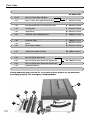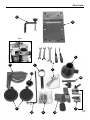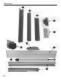
1
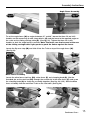
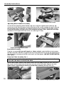
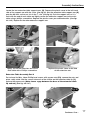
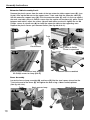
Code: 501242
TS-200 200mm
Basic Table Saw
501248
Leg Stand
Hole assembly instructions including leg stand
extension table and sliding table kits
501254
Sliding Table Kit
700058
R/H Extension Table
Product Code Kits
717218: TS-200 Table Saw
501242: TS-200 Basic Saw
501248: TS-200 Leg Stand
700058: TS-200 R/H Extension Table Kit
501254: TS-200 Sliding Table Kit
Axminster Tool Centre,
Unit 10 Weycroft Avenue, Axminster, Devon EX13 5PH
717218
Table Saw
axminster.co.uk
501242
Basic Saw
Index of Contents
Page No.
02
Index of Contents
Declaration of Conformity
02
Parts Index
03-04-05-06-07
General Instructions for 230V Machines
07-08-09
Specific Instructions/Precautions for the Saw Table
09-10
Specifications
10
Assembly Instructions
11-12-13-14-15-16-17-18-19-20
Illustration & Parts Description
21-22
Setup & Adjustments
23-24
Operating Instructions
25-26
Changing the Saw Blade
26-27
Maintenance
27
Parts Breakdown for TS-200 Table Saw
28-29
Parts List for TS-200 Table Saw
30
Parts List & Breakdown for the Sliding Carriage
31
Declaration of Conformity
Copied from CE Certificate
The undersigned, P. Hartstein authorised by
Qingdao Henry Machinery Co. Ltd.
North Point, Cuihou Road
Tonghe Industrial Zone
Pingdu, Qingdao 266706
manufactured by Qingdao Henry Machinery Co.is in
compliance with the following standards or
standardisation documents in accordance
with Council Directives
93/68/EEC
Model number HM-TS200
symbols below advise that you follow the correct
Warning The
safety procedures when using this machine.
Fully read manual
and safety instructions
before use
02
Ear protection
should be worn
Eye protection
should be worn
Dust mask
should be worn
Two Man
Assembly
HAZARD
Motor gets hot
Parts Index
Model Number:
Quantity
HM-TS200
Kit Order No’s
Description
1 off
Basic Table Saw (with Saw Blade & Riving Knife fitted)
A
501242-717218
2 off
Sliding Carriage Supporting Arms
B
501254
1 off
Push Stick
B1 501242-717218
1 off
Mitre Fence Steel Bar
B2 501242-717218
1 off
Saw Guard Steel Mesh
B3 501242-717218
1 off
Work Clamp Assembly
C
501242-717218
1 off
Sliding Carriage Table
D
501254
1 off
Mitre Fence
E
501242-717218
2 off
Operating Wheel Handles
F
501242-717218
1 off
Mitre Fence Clamping Knob
G
501242-717218
1 off
30mm Hose Support Bracket
H
717218
1 off
Dust Extraction Moulding Support Bracket
I
717218
1 off
4mm, 3mm Allen Keys
J
501242-717218
K
717218-501254
1 off
10-13mm, 13-15mm & 17-19 Spanners
2 off
Screwdrivers
4 off
M6 x 30 Hex Bolts
4 off
M6 x 46 Countersunk Heads & Nuts
4 off
M6 x 16 Hex Bolts & Nuts
2 off
Carriage Arm End Stops
1 off
100mm Dust Extraction Moulding with Inlets 50/30mm
L
501242-717218
1 off
Flip Over Stop
M
501242-717218
1 off
Fence Clamp Assembly
N
501242-717218
1 off
Work Clamp Block
O
501242-717218
1 off
Connecting Block
O
501254-717218
4 off
Leg ‘A’ Frames
P
501248-717218
4 off
Long Struts
Q
501248-717218
4 off
Short Struts
R
501248-717218
4 off
Rubber Feet
S
501248-717218
03
Parts Index
Kit Order No’s
32 off
M8 x 12 Coach Bolts with Nuts
4 off
M8 x 11 Bolts with Large Washer & Nut
T
1 off
Saw Guard with M6 x 25 Coach Bolt & Nut
U 501248-717218
1 off
Carriage Arm
V
1 off
Angle Fence
W 501254-717218
2 off
Extension Table Supporting Arms
X
700058-717218
1 off
Extension Table
Y
700058-717218
1 off
Fence
Z
501242-717218
2 off
Hose 50mm & 30mm
Z1 501242-717218
2 off
Jubilee Clips 50mm & 30mm
Z2 950650,718641
6 off
M6 x 25 Phillip Head Screw
6 off
M6 x 25 Phillip Head Screw with Square Nut
6 off
M6 x 16 Phillip Head Screw with Square Nut
1 off
Instruction Manual
501248-717218
501254-717218
Z3 700058-717218
Having unpacked your saw and its accessories please dispose of any unwanted
packaging properly. The packaging is biodegradable.
A
B1
B2
B3
04
B
Parts Index
C
D
Box
L
E
I
J
G
M
O
F
H
K
N
05
Parts Index
P
Q
R
S
T
U
W1
V
W
W1
X
06
Parts Index
Z1
Z
Y
Z1
Z2
Z3
General Instructions for 230V Machines
Good Working Practices/Safety
The following suggestions will enable you to observe good working
practices, keep yourself and fellow workers safe and maintain your
tools and equipment in good working order.
!
WARNING!!
KEEP TOOLS AND EQUIPMENT OUT
OF THE REACH OF YOUNG CHILDREN
Mains Powered Tools
Primary Precautions
These machines are supplied with a moulded 13 Amp. Plug and 3 core power cable. Before
using the machine inspect the cable and the plug to make sure that neither are damaged. If
any damage is visible, have the damaged item inspected/repaired by a suitably qualified
person. If it is necessary to replace the plug, it is preferable to use an 'unbreakable' type
that will resist damage on site. Only use a 13 Amp plug, and make sure the cable clamp is
tightened securely.
Continues Over....
07
General Instructions for 230V Machines
Fuse as required. If extension leads are to be used, carry out the same safety checks on
them, and ensure that they are correctly rated to safely supply the current that is required
for your machine.
Work Place/Environment
The machine is not designed for sub-aqua operation, do not use when or where it is liable
to get wet. If the machine is to be used outside and it starts to rain (unusual though this
would be in U.K.), stop work and move it inside. If machine has got wet; dry it off as soon
as possible, with a cloth or paper towel.
DO NOT use 230V a.c. powered machines anywhere within a site area that is flooded or
puddled, and do not trail extension cables across wet areas.
Keep the machine clean; it will enable you to more easily see any damage that may have
occurred. Clean the machine with a damp soapy cloth if needs be, do not use any solvents
or cleaners, as these may cause damage to any plastic parts or to the electrical
components.
Keep the work area as uncluttered as is practical, this includes personnel as well as
material.
!
UNDER NO CIRCUMSTANCES SHOULD CHILDREN BE
ALLOWED IN WORK AREAS
It is good practice to leave the machine unplugged until work is about to commence, also
make sure to unplug the machine when it is not in use, or unattended. Always disconnect
by pulling on the plug body and not the cable. Once you are ready to commence work,
remove any tools used in the setting operations (if any) and place safely out of the way.
Re-connect the machine. It is also recommended that you use switched supply outlets.
Carry out a final check e.g. check the cutting tool, drill bit, saw blade etc., is securely
tightened in the machine, check you have the correct speed and function set, check that the
cutting path of the timber is unobstructed, etc..
Most machines these days are fitted with NVR contact switches so that machines cannot
remain inadvertently switched 'ON'. However, it is a good habit to train yourself to check that
the machine is not 'Switched On' prior to connecting the mains supply. (In case you happen
to be using one of the older machines).
Make sure you are comfortable before you start work, balanced, not reaching etc..
If the work you are carrying out is liable to generate flying grit, dust or chips, wear the
appropriate safety clothing, goggles, gloves, masks etc.. If the work operation appears to be
excessively noisy, wear ear-defenders. If you wear your hair in a long style, wearing a cap,
safety helmet, hairnet, even a sweatband, will minimise the possibility of your hair being
caught up in the rotating parts of the machine, likewise, consideration should be given to
the removal of rings and wristwatches, if these are liable to be a 'snag' hazard.
Consideration should also be given to non-slip footwear, etc.
08
DO NOT work with cutting or boring machines of any description if you are tired, your
attention is wandering or you are being subjected to distraction. A deep cut, a lost fingertip
or worse; is not worth it!
General Instructions for 230V Machines
DO NOT use this machine within the designated safety areas of flammable liquid stores or
in areas where there may be volatile gases. There are very expensive, very specialised
machines for working in these areas, THIS IS NOT ONE OF THEM.
Check that cutters, drills, blades etc., are the correct type and size, are undamaged and are
kept clean and sharp, this will maintain their operating performance and lessen the loading
on the machine.
If possible always fit dust extraction to machines that are producing high rates of sawdust,
shavings, chips etc.
Above all, OBSERVE….make sure you know what is happening around you, and USE
YOUR COMMON SENSE.
REMEMBER, YOU ARE ULTIMATELY RESPONSIBLE FOR YOUR OWN SAFETY
THIS MACHINE IS DESIGNED TO CUT TIMBER AND TIMBER DERIVATIVE
PRODUCTS. DO NOT use for any other materials.
Specific Instructions/Precautionsfor the Saw Table
Make sure the saw blade is the correct type for the job in hand.
DO NOT force the saw, if the saw begins to 'stall' you are 'forcing the cut' or over working
the saw.
Ensure that the saw blade is clean and sharp. Resin build up on the blades will increase the
friction of the saw passing through the timber, and cause over heating of the blade, blunt
teeth will work harder tearing the fibre of the timber as opposed to shearing it, also with
subsequent overheating. Both faults unnecessarily load the machine beyond normal usage,
and shorten its longevity.
DO NOT use blades that are deformed in any way.
DO NOT remove the blade guard. The design of the riving knife on the machine will not
allow for slotting or 'blind' grooving, so there is no reason to remove the guard.
DO NOT remove the riving knife.
DO NOT use any blades that cut a smaller kerf than the riving knife thickness.
Make sure the riving knife is correctly adjusted to the blade and is securely fastened.
If the table insert becomes damaged or broken, and will not support the timber 'up close' to
the blade, replace it.
DO NOT start the saw with the workpiece touching the blade.
DO NOT commence sawing until the blade has run up to full speed.
After switching off, never try to slow the saw down more quickly by applying side pressure
(with a piece of wood?) to the blade.
Apply the old joiner's adage of never getting hands within one handbreadth of the blade.
Leave the machine disconnected from the mains supply until you are about to commence
work.
Continues Over....
09
Specific Instructions/Precautions for the Saw Table
ALWAYS disconnect the machine if you are leaving it unattended.
NEVER leave the vicinity of the machine unless the blade has come to a complete stop.
DO NOT attempt to carry out any maintenance, corrective work, setting up etc., unless the
machine is disconnected from the mains supply.
If any tools have been used during setting up procedures, make sure they are removed
from the machine and stowed safely away.
DO NOT attempt to carry out cross cutting operations 'freehand', always use the mitre fence
for small stuff and the sliding carriage for larger work pieces.
Unless you are an experienced machine operator, do not attempt to 'rip' freehand, always
use the guiding facility of the rip fence.
It is perfectly acceptable to support guide and feed the timber with your hands whilst
ripping stuff of some length, however, as you approach the blade ensure that the push stick
is to hand, and you use it.
REMEMBER the emphasis of the 'push' should be between the blade and the fence and
close to the fence. Use your free hand to support and guide the material on the offside of
the saw blade and at least 100mm away from it. If the timber does not extend to at least
100mm to the offside of the saw blade, the material possibly? does not need guiding or
supporting.
CHECK (especially on site), that there are no foreign objects e.g. old nails, screws, small
stones etc embedded in the material you are about to cut. If necessary take a wire brush to
the timber before working.
If you are being assisted whilst using the saw (by a 'take off' or 'support' number?),
remember there is only one sawyer at a machine, and they stand in front of it. The assistant
does not push, pull, guide etc., unless specifically asked or instructed to do so by the
sawyer.
Specification
Model
Rating
Power
Blade Dia/Bore
Blade Tilt
Max Depth of Cut @ 45˚
Max Depth of Cut @ 90˚
Max Crosscut
Max Ripping Width
Table Size
Table Height
Dust Extraction Outlet
Min Extraction Airflow Required
Overall L x W x H
Weight
10
TS-200 Basic
Hobby
1,100W
200mm/30mm
0°-45°
40mm
58mm
620mm
150mm standard, 750mm with R/H Table Kit
535 x 400mm
320mm
100mm
500m³/hr
535 x 400 x 325mm
55kg
Assembly Instructions
Initial Assembly
Please take some time to read the section entitled “Identification and Parts Description” to
identify the various parts of your machine so that you are familiar with the terminology we
will use to enable you to set up and operate your table saw safely and correctly.
Assembling the stand
Locate and identify the 4 legs (P), the short struts (R)
and the long struts (Q) for the stand, and the packet
containing 32 M8 x 10mm coach bolts, washers and
nuts.(T).
P
Fig 1
Q
Using the M8 x 10mm coach bolts, nuts and washers
bolt together two ‘A’ frames using two legs (P) one long
strut (R) in the middle and one short strut (Q) at the
top. Tighten the nuts only ‘finger tight’ at this time.
(See fig 1).
When the two ‘A’ frames have been assembled,
select one, turn it upside down on a flat surface and
loosely bolt the ‘short strut’ (R) and long strut (Q) in
place (See fig 2). Attach the other “A’ frame and bolt the
remaining struts for the other side.
R
Q
R
When all the components are assembled, using the flat
surface as a reference, tighten up all the nuts. Turn the
stand on it’s side and place the four rubber feet (S) to
the ends of the ‘A’ frames. Upright the frame and stand
on the floor. (See fig 3).
S
Fig 2
Fig 3
11
Assembly Instructions
Attaching the Saw Guard Steel Mesh
Locate the Saw Guard Steel Mesh (B3), turn the Saw Bench (A) upside down and remove the four
phillips screws & washers to each corner of the frame. Lay the Saw Guard Steel Mesh on top of the
frame and replace the phillip screws & washers to secure it in position. (See fig 4 & 4a).
Fig 4
A
Fig 4a
B3
Attaching the Saw Bench to the Stand
Phillips screw & washer
With assistance, place the Saw Bench (A) onto the stand. Align the four mounting
holes at the base of the Saw Bench with the four mounting holes at each corner
of the stand. Using four M8 x 11mm hex bolts, large washers & nuts (T) secure
the Saw Bench to the stand. (See fig 5 & 5a).
Fig 5a
Fig 5
M8 x 11mm hex bolt, washer & nut
Assembling the Sliding Carriage Table
Attach the two sliding carriage support arms (B) to the underside of the cast iron saw
bench (A) using four M6 x 50mm countersink heads & M6 nuts, secure using a 4mm allen
key (J). (See figs 6,7).
Fig 7
Fig 6
B
12
J
M6 Countersink Head
Secure the support arms with the
supplied 4mm allen key
Assembly Instructions
Assembling the Sliding Carriage Table
Place an M6 x 16mm hex bolt in each of the four clearance holes on both support arms (B),
and loosely put an M6 nut and washer on the bottom of each. (See fig 8). Slide the
extruded carriage arm (V) onto the four M6 x 16mm bolts. (See fig 9).
Fig 8
M6 x 16mm bolts into each of the four
clearance holes in both support arms
Fig 9
V
Slide the extruded carriage arm onto the
four M6 x 16mm bolts
Locate the sliding carriage table (D) and slide it onto the carriage arm (V), see fig 10. Using
a level or straight edge place across the sliding table (D) and the saw bench (A), fit the four
M6 x 30mm Hex bolts to the underside of the carriage support arms (B) and adjust until the
sliding table (D) is level with the saw bench. (See figs 11 & 12).
Fig 10
Fig 11
B
D
M6 x 16mm hex bolt
Two M6 x 30mm hex bolt
V
When both the tables are level tighten the four M6 nuts on the M6 x 16mm hex bolts
underneath the carriage arms (B), see fig 11. Lastly fit the carriage arm end stops (K) to
each end of the carriage arm (V). (See fig 13).
Fig 12
Fig 13
K
13
Assembly Instructions
Angle Fence Assembly
Put to hand the work clamp block (O), and slide it onto the T-slot on the angle fence (W).
Locate the connecting block (O) and slide it onto the angle fence as before. (See fig 14).
Slide the T-bolt on the base of the connecting block (O) into the T-slot on the sliding
carriage table (D), see fig 16. Locate the plastic block (W1) and using the two phillips
screws secure it to the end of the angle fence (W) (See fig 15).
Fig 15
Fig 14
Connecting block
Work clamp block
W1
Locate the work clamp (C), slot the work clamp into the 20mm hole in the work clamp block
(O), secure in position with the lift and shift handle. (See figs 16 & 17). To set the angle
fence at 90˚, push the angle fence (W) up against the stop (See fig 18).
Fig 16
O
20mm Hole
Fig 17
C
T-bolt
Fig 19
Fig 18
90˚ stop
Note: Make sure the plastic block on the end is just missing the blade. Using a 90˚ square
check that the blade is at 90˚ to the angle fence (W), (see fig 19). When correct
tighten the lift and shift handle on the connecting block (O). (See fig 15). If the angle fence
(W) is not set to 90˚, undo the grub screw to the side of the sliding carriage table (D),
using a flat screwdriver turn the eccentric bush until the angle is correct. (See figs 20 & 21).
14
Assembly Instructions
Angle Fence Assembly
Fig 21
Fig 20
To set the angle fence (W) to angles between 45˚ and 90˚ loosen the three lift and shift
handles on the connecting & work clamp blocks (O) and the fence to the required angle on
the scale on the sliding carriage table (D). (See figs 22). Tighten the three lift & shift
handles to lock the angle fence in position. Note: The fence can also be used at the rear
of the sliding carriage table if you prefer to push the timber against the fence.
Locate the flip over stop (M) and slide it into the T-slot on top of the angle fence (W).
(See fig 23).
Fig 23
Fig 22
M
W
Mitre Fence Assembly
Locate the mitre fence steel bar (B2), mitre fence (E) and clamping knob (G). Slot the
threaded pin on the steel bar (B2) through the curved slot in the mitre fence (E) and screw
the clamping knob (G) to clamp the assembly together. (See figs 24 & 25). Slide the Mitre
fence assembly into the machined T-slot on the saw table. (See fig 26).
Fig 24
Fig 25
E
G
B2
Continues Over....
15
Assembly Instructions
J
Fig 26
Fig 27
a
F
Tilt operating wheel handle
Operating Wheel Handles Assembly
Locate the two operating wheel handles (F) and, using the supplied 3mm allen key (J),
secure one to the tilt mechanism shaft to the front of the saw by undoing the grub screw on
the operating wheel handle (F) and sliding it onto the shaft, making sure the grub screw is
in line with machined slot (a), in the shaft. Retighten the grub screw. Repeat for the height
mechanism to the right hand side of the saw. (See figs 27 & 28).
Fig 29
Fig 28
U
Height operating wheel handle
Saw Guard Assembly
Find the saw guard (U) (you will require a 10mm socket), undo the M6 nut and remove
the M6 coach bolt. Slot the saw guard over the riving knife and line up the pre-drilled hole in
the riving knife and replace the M6 coach bolt & nut and tighten. (DO NOT OVERTIGHTEN)
(See fig 29).
Extension Table Assembly Part 1
NOTE: 501242 COMES WITH THE FENCE SUPPORTING ARM ONLY AND DOES NOT
INCLUDE THE BACK SUPPORTING ARM.
Put to hand six M6 x 25mm Phillip head screws with nuts (Z3), remove the nuts and place
the screws into the three holes to the front and rear of the main table. Replace the nuts.
(Note: Leave a gap between the base of the table and nut) (See figs 30 & 31).
Fig 31
Fig 30
Z3
16
M6 x 25mm Phillip head screw & nut
Assembly Instructions
Locate the two extension table support arms (X). Remove the plastic cover to the left hand
side of the support arm with the scale. (See fig 32). Slot the extension table support arm (X)
onto the M6 nuts so that nut sits in the T -slot. (See fig 33) Push the support arm so it is
flush with the end of main table and lightly secure the extension support arm to the main
table using a phillips screwdriver. Replace the plastic cover you removed earlier. (See figs
34 & 35). Repeat for the other extension support arm.
Fig 32
X
Fig 33
Plastic Cover
Fig 34
Lightly secure the extension arm to the
main table with a Phillips screwdriver
Fig 35
Replace the plastic cover to the end
of the extension arm
Extension Table Assembly Part 2
Put to hand six M6 x 16mm Phillip head screws with square nuts (Z3), remove the nuts and
place safely aside. Slot the screws into each of the 6 holes on the extention table lip (Y),
replace the square nuts (Note: Leave a gap between the base of the extension table
lip and nut) (See figs 36 & 37).
Fig 36
Fig 37
Continues Over....
17
Assembly Instructions
Extension Table Assembly Part 2
Remove the plastic covers from the ends of the two extension table support arms (X), (see
fig 38). Offer up the M6 nuts to the support arms T-slots and slide the extension table (Y)
into the extension support arms (X). Push the extension table (Y) until it is flush up against
the main saw table, place six Phillips screws into the captive nut locations (a), place a level
between both tables, adjust the screws (a) until both tables are level & tighten the six M6
Phillips screws & square nuts (b) to clamp the extension table to the supporting arms.
Replace the plastic covers you removed earlier. (See figs 39,40 & 41).
Fig 38
Fig 39
X
b
T-slot
a
Plastic Cover
M6 x 16 Phillip
screw & square nut
Fig 41
Fig 40
a
Y
Using a Phillips screwdriver level & tighten
the Phillip screws to clamp (X & Y)
Extension table assembled
Fence Assembly
Locate the fence clamp assembly (N) and fence (Z) Slot the steel square clamp into the
T-slot to the end of the fence (Z) and tighten the bolt using a 10mm socket/spanner.
(See figs 42 & 43).
T-slot
Steel square clamp
10mm Socket
Fig 43
Fig 42
N
Z
18
Assembly Instructions
Fence Assembly
Lower the fence assemby so the clamp assembly (N) slots over the extention table support
arm (X), clamp the fence assembly in position by turning the knob clockwise. (See figs 44 &
45).
Note: Check that the fence is parallel to the saw blade by sliding it up against it. If the fence
is out of alignment loosen the steel square clamp bolt beneath the clamp assembly (N) and
adjust until correct, re-tighten the bolt. (See figs 43 & 46).
Note: Lubricate the Fence supporting arm (X) and the underside of the clamp assembly (N)
so the fence assembly runs smoothly back and forth.
Fig 44
Fig 45
Z
N
Fig 47
Fig 46
Dust Extraction Assembly
Locate the 50 & 30mm hoses (Z1), jubilee clips (Z2), dust extraction moulding support
bracket (I) & 100mm dust extraction moulding (L). Place one of the large jubilee clips over
the end of the 50mm hose and fit the hose over the table saw’s dust extraction outlet &
tighten. (See fig 48). Do the same as before & place the 30mm hose over the end of the
saw guard’s dust extraction outlet (U) & tighten. (See fig 49).
Fig 49
Fig 48
Z2
50mm hose
30mm hose
Continues Over....
19
Assembly Instructions
Dust Extraction Assembly
(717218 Only) Remove the nuts, bolts & washers from the 30mm hose support bracket
(H), line up the pre-drilled holes to the underside of the rear extention support arm (X) &
secure using the nuts,bolts & washers you removed earlier. (See figs 50 & 51).
Locate the dust extraction moulding support bracket (I) & slot the bracket’s ring over the
end of the 50mm inlet on the dust extraction moulding (L). (717218 Only) Slot the 30mm
hose through the support bracket ring (H) (717218 Only), locate a jubilee clip (Z2), place
over the end of the hose & slot the hose onto the 30mm inlet on the dust extraction
moulding (L) & secure. (See fig 52).
(717218 Only) Remove the nuts, bolts & washers from the support bracket (I), line up the
pre-drilled hole to the underside at the end of the extention support arm (X) & secure using
the nut, bolt & washer you removed earlier. (See fig 53).
Loosen the support bracket ring (I), by undoing the clamping screw, see fig 53, slot the
50mm hose through the ring and onto the 50mm inlet on the dust extraction moulding (L),
retighten the clamping screw. (See figs 52 & 53).
X
Nuts, bolts & washers
Fig 51
Fig 50
H
Z2
L
Fig 53
Fig 52
I
I
30mm hose
50mm inlet
Support bracket ring
20
Clamping screw
Illustration & Parts Description
G
W
C
E
U
D
M
Z
W1
Y
O
N
A
V
F
F
NVR On/Off
switch shroud
X
R
P
T
S
Q
A Saw Bench
M Flip Over Stop
B1 Push Stick
O Work Clamp/Connecting Blocks
C Work Clamp Assembly
P Leg ‘A’ Frames
D Sliding Carriage Table
Q Long Struts
E Mitre Fence
R Short Struts
F Operating Wheel Handles
S Rubber Feet
G Mitre Fence Clamping Knob
T M8 x 12 Coach Bolts with Nuts
H 30mm Hose Support Bracket
U Saw Guard
I Dust Extraction Support Bracket
V Carriage Arm
L 100mm Dust Extraction Moulding
W W1 Angle Fence/Plastic Block
21
Illustration & Parts Description
Z
D
X
Y
V
I
B1
Z1
A
Z1
L
22
H
X Extension Table Support Arms
Z Fence
Y Extension Table
Z1 Hoses 50mm & 30mm
Setup & Adjustments
Adjusting the Riving Knife
Raise the saw blade to its highest point and remove the saw blade guard. Remove the four
hex screws and place carefully aside, remove the table insert. Using the spanner provided
loosen the riving knife and adjust until the tip of the riving knife is 3mm away from the saw
blade & re-tighten. (See fig 54).
NOTE: Check that the riving knife is parallel to the saw blade by placing the fence
up against them. (See fig 55).
Z
Fig 54
Fig 55
Adjusting the Fence to the Blade
The fence assembly must be parallel to the saw blade for producing accurate cuts. Firstly
loosen the fence clamp assembly knob (N), slide the fence until it reads “ZERO” on the
table support arm scale (X). (See figs 56 & 57).
Fig 57
Fig 56
Z
X
“Zero”
NOTE: Use the ‘T’ slot to the right side of the saw blade as a reference to check the fence is
parallel. (See figs 58 & 59). Regularly check the fence is parallel to ensure a perfect cut.
Fig 58
“T” Slot
Fig 59
Continues Over....
23
Setup & Adjustments
Adjusting the Fence to the Blade
The fence (Z) can be repositioned to face the opposite direction for guiding thin timber
pieces through.
Loosen the square clamp bolt beneath the clamp assembly (N), See fig 57, turn the fence
(Z) around so the large surface of the fence is pointing away from the blade, re-attach the
fence clamp assembly (N). The two illustrations below, figs 60 & 61, shows the fence in
both positions.
Fig 60
Thin Timber
Thick Timber
Fig 61
Z
Z
The small surface of the fence is for
guiding thin timber through.
The large surface of the fence is for
guiding thick timber through.
Adjusting the Cutting Height
Adjust the blade height with the hand wheel (F), see fig 62, so that the blade teeth are
protruding through the work piece.
Fig 63
Fig 62
A
B
F
Adjusting the pivot
Release the locking handle (A), the saw can be angled up to a maximum of 45˚ by turning
the hand wheel (B). (See fig 63).
NOTE: If the blade is at maximum height, it will need to be lowered by 10mm when the
pivot angle is 30˚ or more.
24
Operating Instructions
!
NOTE: Before using your table saw, go round and make sure everything is
secure, fastened down, that all tool, are cleared away from the work area.
!
CHECK the blade for sharpness, missing teeth, resin buildup, etc., clean if
necessary. Check the blade is securely clamped in place. (i.e. not loose).
!
CONNECT THE SAW TO THE MAINS SUPPLY
Give the machine a 'quick' burst check ( i.e. quick ON-OFF) to ensure everything is O.K. If
everything is satisfactory, the table saw is ready for use.
!
!
WARNING!
KEEP TOOLS AND EQUIPMENT OUT
OF THE REACH OF YOUNG CHILDREN
UNDER NO CIRCUMSTANCES SHOULD
CHILDREN BE ALLOWED IN WORK AREAS
Feeding Work by Hand
!
CONNECT A DUST EXTRACTION VACUUM TO THE
DUST EXTRACTION OUTLET ON YOUR TABLE SAW
Start up the saw, wait until it has reached full speed and slowly feed the timber through using
both handles, (making sure to keep your hands well clear of the blade and using a
push stick for small pieces), until the timber is behind the riving knife. Switch off the saw,
wait until the blade has come to a complete stop and remove the timber. (See figs 64 & 65).
Fig 65
Fig 64
!
NOTE: Secure larger pieces of timber to the table by using the clamp assembly (C), see
page 20.
Cutting Narrow pieces
Use the small flat surface of the fence (Z) to cut thin timber narrower that 120mm.
(See fig 60) (Use a push stick).
25
Operating Instructions
The Mitre Fence
The mitre fence can be mounted on either side of the saw blade in the two ‘T’ slots, pre
machined into the saw table. (See fig 26). The mitre fence can be angled from 90˚ to 45˚
degrees. (See fig 66).
Fig 66
THE BLADE IS SET
AT AN ANGLE LESS
THAN 90˚ DEGREES
FOR BEVEL CUTS
HOLD THE
WORK FIRMLY
LOCK THE
MITRE FENCE
AND HOLD THE
WORK FIRMLY
BLADE GUARD
Changing the Saw Blade
!
DISCONNECT THE SAW FROM THE MAINS SUPPLY
Raise the saw blade to its highest point, remove the saw blade guard, remove the
four hex screws that secure the table insert, place carefully aside and remove the table
insert. Using the spanner provided, put the spanner onto the flats on the nut.
(See figs 67 & 68).
Note: Be careful not to disturb the shims beneath the table insert, as the shims are
set so the table insert is level with the table surface.
Slacken off the saw bolt (remember right hand thread). Remove the saw nut, then remove
the sawplate washer and the saw blade. (See figs 68 & 70). Now is a good time to give the
interior of the machine, the dust extraction channels, etc. a thorough clean. Check the new
blade for damage, missing teeth,sharpness etc. Fit the new blade, ensure that the teeth are
pointing towards the front of the machine. Put the sawplate washer onto the shaft and twist
on the saw bolt. Spin the bolt up finger tight and check the saw is correctly seated.
Fig 67
26
Hex screw
Table insert
height shims
Undoing the
saw bolt
Fig 68
Changing the Saw Blade
Fig 69
Sawplate washer
Fig 70
Remove the
saw blade
Tighten up the saw bolt, check the riving knife is aligned with the saw blade, and correctly
positioned. Replace the table insert and secure with the 4 hex screws. Replace the saw
blade guard. When everything is satisfactory, turn the saw blade once by hand to check it
doesn't foul anywhere.
Reconnect the machine to the mains supply. Give the machine a 'quick' burst check ( i.e.
quick ON-OFF) to ensure everything is O.K. If everything is satisfactory, continue to use the
machine. Check the old blade for sharpness, missing teeth, resin build up, etc., clean if
necessary and send for refurbishment/resharpening if required. If the blade is not to be
re-sharpened, clean and pack away in its storage case.
Maintenance
Keep the saw as clean and free from saw dust build up as is practical. Periodically, remove
the saw gullet and vacuum out and clean out the saw box and the extraction housing.
Remove any resin build up in the saw box, using a proprietary resin cleaner.
Clean the threaded drive shafts of the rise and fall and tilt mechanisms. At the same time
check the belt drive, i.e. the belt is not 'glazing' with resin build up, likewise with the pulley
wheels. Check the belt tension. If the belt is becoming slack, loosen the motor hold down
bolts and drive the motor backward with its adjusting bolt.
Check the saw blade regularly for chipped, missing, damaged teeth etc. and remove any
resin build up from the blade, riving knife etc.
If you have finished using the saw bench, clean above and below the work table and using
a damp cloth wipe the saw bench over. If the saw bench is not going to be used for a period
of time, smear a light coat of oil over the work table and place a dust sheet over the saw
bench.
27
Parts Breakdown for TS-200 Table Saw
28
Parts Breakdown for TS-200 Table Saw
29
Parts List for TS-200 Table Saw
30
Parts LIst & Breakdown for the Sliding Carriage
31
Please dispose of packaging for the product in a responsible manner. It is suitable for recycling.
Help to protect the environment, take the packaging to the local recycling centre and place into
the appropriate recycling bin.
Only for EU countries
Do not dispose of electric tools together with household waste material. In observance of
European Directive 2002/96/EC on waste electrical and electronic equipment and its
implementation in accordance with national law, electric tools that have reached the end of
their life must be collected separately and returned to an environmentally compatible recycling
facility.