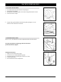
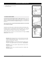
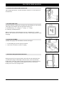
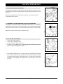
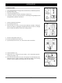
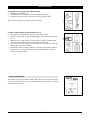
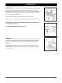
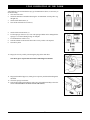
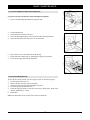
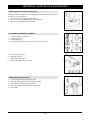
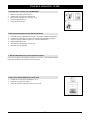
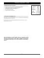
1
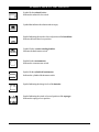
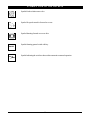
Electronic Service
Manuals
This electronic document is provided as a service to our customers. We do not create the contents of the information contained in
this document. Should you have detailed questions pertaining to
the information contained in this document, you may contact Michco,
or the manufacturer which provided the original information in this
electronic deliverable. Michco’s only part in this electronic deliverable was the electronic assembly process.
You may contact Michco through the following methods:
Phone (517) 484-9312 or (800) 331-3339 MI, OH, IN only
2011 N. High St. -- Lansing, Michigan -- 48906
Fax: (517) 484-9836
Email: [email protected]
Web site: www.Michco.Com
Parts Web site: www.FloorMachineParts.Com
Order Parts on Line at:
www.FloorMachineParts.Com
Directly to Parts & Service:
By Email: [email protected]
By Fax: (517) 702-2041
By Voice: Use numbers above.
Serving the Cleaning Industry Since 1922
Notice: All copyrighted material remains property of original owners, all trademarks are property of respective
owners. Manuals are subject to Manufacturer’s reproduction limitations. Originals or reproductions were provided
by manufacturers through a request. We make no warranty as to the correctness of information provided in this
document and you assume all risk.
ScrubMaster 30R
OPERATING & MAINTENANCE
INSTRUCTIONS
INTRODUCTION
READ THIS BOOK
This operator’s book has important information for the
use and safe operation of this machine. Read this book
carefully before starting the machine. Keep this book
and tell all operators to read the book. If you do not
follow the instructions, you can cause an injury or damage equipment, furniture or buildings.
For new books write to:
Pacific
2259 S. Sheridan
Muskegon, MI 49442-6252
Carefully inspect all components to ensure that there is
no concealed freight damage. If such damage is discovered, file a “CONCEALED DAMAGE REPORT”
immediately with the delivering carrier.
The contents of this manual are based on the latest product information available at the time of publication. Pacific Steamex reserves the right to make changes or
improvements to its machines without notice.
FOR YOUR CONVENIENCE, RECORD THE
FOLLOWING INFORMATION:
MODEL
SERIAL NUMBER
PART NUMBER
DATE PURCHASED
TABLE OF CONTENTS
OPERATOR AND SAFETY INSTRUCTIONS
○
SYMBOLS USED ON THE MACHINE
MACHINE PREPARATION
○
○
○
○
○
○
○
○
○
○
○
○
○
○
○
○
○
○
○
○
○
○
○
○
○
○
○
○
○
○
○
○
○
○
○
○
○
○
○
○
○
○
○
○
○
○
○
○
○
○
○
○
○
○
OPERATION
○
○
○
○
○
○
○
○
○
○
○
○
○
○
○
○
○
○
○
○
○
○
○
○
○
○
1. STARTING WORK
2. MANUAL OPERATION
3. TRACTION
4. BRAKES
5. HORN
6. ALARMS
○
○
○
○
○
○
○
○
○
○
○
○
○
○
○
○
○
○
○
○
○
○
○
○
○
○
○
○
○
○
○
○
○
○
○
○
○
○
○
○
○
○
○
○
○
○
○
○
○
○
○
○
○
○
○
○
○
○
○
○
○
○
○
○
○
○
○
○
○
○
○
○
○
○
○
○
○
○
○
○
○
○
○
○
○
○
○
○
○
○
○
○
○
○
○
○
○
○
○
○
○
○
○
○
○
○
○
○
○
○
○
○
○
○
○
○
○
○
○
○
○
○
○
○
○
○
○
○
○
○
○
○
○
○
○
○
○
○
○
○
○
○
○
○
○
○
○
○
○
○
○
○
○
○
○
○
○
○
○
○
○
○
○
○
○
○
○
○
○
○
○
○
○
○
○
○
○
○
○
○
○
○
○
○
○
○
○
○
○
○
○
○
○
○
○
○
○
○
○
○
○
○
○
○
○
○
○
○
○
○
○
○
○
○
○
○
○
○
○
○
○
○
○
○
○
○
○
○
○
○
○
○
○
○
○
○
○
○
○
○
○
○
○
○
○
○
○
○
○
○
○
○
○
○
○
○
○
○
○
○
○
○
○
○
○
○
○
○
○
○
○
○
○
○
○
○
○
○
○
○
○
○
○
○
○
○
○
○
○
○
○
○
○
○
○
○
○
○
○
○
○
○
○
○
○
○
○
○
○
○
○
○
○
○
○
○
○
○
○
○
○
○
○
○
○
○
○
○
○
○
○
○
○
○
○
○
○
○
○
○
○
○
○
○
○
12
○
○
○
○
○
11
○
○
○
○
○
○
○
○
○
10
○
○
○
9
○
○
○
○
○
○
○
○
○
○
○
○
7
8
○
○
○
○
○
○
○
○
6
○
○
○
○
○
○
○
○
○
○
○
○
4
○
○
○
3
○
○
○
○
○
○
○
○
○
○
○
○
○
○
○
○
○
○
○
○
○
○
○
○
○
○
○
○
○
○
○
○
○
○
○
○
○
○
○
○
○
○
○
○
○
○
○
○
○
○
○
○
○
○
○
○
○
○
○
○
○
○
○
○
○
○
○
○
○
○
○
○
○
○
○
○
○
○
○
○
○
○
○
○
○
○
○
○
○
○
○
○
○
○
○
○
○
○
○
○
○
○
○
○
○
○
○
○
○
○
○
○
○
○
○
○
○
○
○
○
○
○
○
○
○
○
○
○
○
○
○
○
○
○
○
○
○
○
○
○
○
○
○
○
○
○
○
○
○
○
○
○
○
○
○
○
○
○
1. CLEANING THE RECOVERY TANK AND FILTER
2. CLEANING THE SQUEEGEE
3. CLEANING THE SOLUTION TANK AND FILTER
4. DISASSEMBLY OF THE ROTATING BRUSHES
5. HOPPER CLEANING
WEEKLYMAINTENANCE
○
○
○
○
○
○
○
○
○
○
○
○
○
○
○
○
○
○
○
○
○
○
○
○
○
○
○
○
○
○
○
○
○
○
○
○
○
○
○
○
○
○
○
○
○
○
○
○
○
○
○
○
○
○
○
○
○
○
○
○
○
○
○
○
○
○
○
○
○
○
○
○
○
○
○
○
○
○
○
○
○
○
○
○
○
○
○
UPON COMPLETION OF THE WORK
DAILY MAINTENANCE
○
○
○
○
○
○
○
○
○
1. UNPACKING THE MACHINE
2. BATTERY INSTALLATION
3. CHARGING THE BATTERIES
4. CONNECTING THE BATTERY CONNECTOR
5. BATTERY INDICATOR
6. SQUEEGEE ASSEMBLY
7. ADJUSTING THE SQUEEGEE INCLINATION
8. ADJUSTING THE SQUEEGEE HEIGHT
9. CYLINDRICAL BRUSHES - ADJUSTING THE HEIGHT
10.ROTARY BRUSH ASSEMBLY
11. HOPPER
12. RECOVERY TANK
13. SOLUTION WATER
○
○
15
16
17
18
○
○
13
14
19
○
1. REPLACEMENT OF THE REAR SQUEEGEE BLADE
2. REPLACEMENT OF THE FRONT SQUEEGEE BLADE
3. CLEANING THE SQUEEGEE HOSE
ADDITIONAL MAINTENANCE PROCEDURES
○
○
○
○
○
○
○
○
○
○
○
○
○
○
○
○
○
○
○
○
○
○
○
○
○
○
○
○
○
○
○
○
○
○
○
○
20
○
1. REPLACEMENT OF THE SPLASH GUARD
2. CYLINDRICAL BRUSH REPLACEMENT
3. RECOVERY TANK CLEANING
TROUBLE SHOOTING GUIDE
○
○
○
○
○
○
○
○
○
○
○
○
○
○
○
1. INSUFFICIENT WATER ONTO THE BRUSH
2. THE SQUEEGEE DOES NOT DRY THE FLOOR WELL
3. THE MACHINE DOES NOT CLEAN SATISFACTORILY
4. VACUUM MOTOR DOES NOT FUNCTION
5. MACHINE WILL NOT START
6. EXCESSIVE FOAM PRODUCTION
○
WARRANTY POLICY
○
○
○
○
○
○
○
○
○
○
○
○
○
○
○
○
○
○
○
○
○
○
○
○
○
○
○
○
○
○
○
○
○
○
2
○
○
○
○
○
○
○
○
○
○
○
○
○
○
○
○
○
○
○
○
○
○
○
○
○
○
○
○
○
○
○
○
○
○
○
○
○
○
○
○
○
○
○
○
○
○
○
○
○
○
○
○
○
○
○
○
○
○
○
○
○
○
○
○
○
○
○
○
○
○
○
○
○
○
○
○
○
○
○
○
21
○
22
○
○
○
24
OPERATOR AND SAFETY INSTRUCTIONS
For the safe operation of this machine, read and understand all instructions before using this machine.
WARNING: To reduce the risk of fire, electric shock or injury:
1. You must have training in the operation of the machine before using it. READ THE
INSTRUCTION BOOK. If you do not understand any instruction, ask your supervisor.
2. Make sure all labels, decals, warnings, cautions and instructions are fastened to the machine.
3. Read the labels carefully on the machine. Do not cover them for any reason and replace them if
damaged.
4. Do not operate this machine unless it is completely assembled, inspect the machine carefully before
operation.
5. Pay close attention to other people and especially children while operating this machine.
6. Be a careful driver, do not strike shelving or scaffolding, especially where there is a danger of falling
objects.
7. Machines can cause an explosion when operated near flammable materials and vapors. Do not use
this machine with or near fuels, grain dust, solvents, thinners, or other flammable materials.
8. In case of fire, use a powder extinguisher. Do not use water.
9. Do not use this machine as a means of transport.
10. Do not use acid solutions that could damage the machine.
11. Do not mix different detergents causing harmful odors.
12. Do not place any liquid containers on the machine.
13. To prevent floor damage, stop the brushes when the machine is standing still.
14. Adjust your speed to the conditions of the floor.
15. Do not turn the machine on a ramp. Do not stop and leave the machine on a ramp or incline.
16. When the machine is parked, take out the key and set the parking brake.
17. Empty the solution tank before lifting it.
18. During any maintenance operation disconnect the power supply from the machine.
19. Lead acid batteries generate gases that can cause an explosion. Read the instruction manual supplied
with the battery charger. Keep sparks and flames away from batteries. NO SMOKING. Charge
the batteries only in an area with good ventilation.
20. Do not use a charger if the power cord is damaged.
21. Always wear eye protection and protective clothing when working near batteries. Remove all jewelry. Do not put tools or other metal across the battery terminals, or the tops of the batteries.
22. Check the level of the electrolyte every time you charge the batteries. If the level is low, ADD
DISTILLED WATER ONLY.
23. Maintenance and repairs must be performed by authorized Service Centers only. Make adjustments
according to the specifications given in the service manual for this machine.
24. Keep the electrical parts of the machine dry. Do not wash the machine with direct water jets or high
pressure, nor with corrosive material. For storage, keep the machine in a dry building.
25. Water solutions or cleaning materials used with this type of machine can leave wet areas on the floor
surface. These areas can cause a dangerous condition for the operator or other persons. Always put
CAUTION signs near the area you are cleaning.
26. Do not reach under shrouds with fingers, hands, or toes when machine is running.
3
SYMBOLS USED ON THE MACHINE
Symbol for the solenoid valve:
Indicates the solenoid valve switch.
Symbol that indicates the solution tank is empty.
RESERVE
Symbol indicating the raised or lowered position of the brush base:
Indicates the brush base lever position.
Symbol for the counter-rotating brushes.
Indicates the brush motor switch.
Symbol for the vacuum motor:
Indicates the vacuum motor switch.
Symbol for the cylindrical brush motor.
Indicates the cylindrical brush motor switch.
Symbol indicating the charge levels of the batteries.
Symbol indicating the raised or lowered position of the squeegee:
Indicates the squeegee lever position.
4
SYMBOLS USED ON THE MACHINE
Symbol for the solution water valve.
Symbol for speed control in forward or reverse.
Symbol denoting forward or reverse drive.
Symbol denoting general switch with key.
ON/OFF
AUTO
Symbol indicating the switch to choose either automatic or manual operation.
MAN
5
MACHINE PREPARATION
1. UNPACKING THE MACHINE
1.
2.
3.
4.
Use a fork truck to move the machine when packaged.
Take off the outer package
The machine is fixed on the pallet with wooden wedges that block the wheels.
Take off the wheel wedges.
5.
Using a ramp, get the machine down from the pallet, pushing it in reverse
motion. Avoid violent blows to the base.
2. BATTERY INSTALLATION
The six 6 volt, 305 AH batteries fit in the compartment under the solution tank.
For battery maintenance and charging, follow the instructions
provided by the battery supplier.
Installation Instructions:
1. Make sure the solution tank is empty.
2. Close the valve (1) located under the operator.
3. Disconnect the hose by pushing the connector (2) down.
4. Lift the solution tank.
5. Place the batteries in their compartment.
6
MACHINE PREPARATION
6.
7.
Unlock, then lower the solution tank.
Reconnect the hose.
3. CHARGING THE BATTERIES
NEVER ALLOW THE BATTERIES TO RUN COMPLETELY DOWN, recharge them
within a few minutes after the battery indicator starts to blink “0” on the display (see
section 5). Never leave the batteries completely discharged, even if the machine is not
being used.
When charging the batteries, keep the solution tank lifted and make sure the solution
tank is empty before lifting it.
Turn the key to the OFF position. Connect the DC connector on the charger to the
DC battery connector (1), located in the lower part of the operator’s seat. Connect the
AC charger plug to a receptacle that has the correct voltage and frequency for your
charger. Make sure the receptacle is connected to the electrical ground.
Check the electrolyte level at least every 20 times the batteries are charged. Add only
distilled water if the level is low.
WARNING! When charging the batteries, follow all the instructions provided
with this manual and the battery charger. Trained staff must carry out the
installation and maintenance operations.
WARNING! Fire Danger: Lead acid batteries generate gases that can cause
an explosion. Keep sparks and flames away from batteries. NO SMOKING!
WARNING! To prevent an explosion, charge the batteries only in an area
with good ventilation.
WARNING! Always wear eye protection and protective clothing when
working near batteries.
7
MACHINE PREPARATION
4. CONNECTING THE BATTERY CONNECTOR
After charging the batteries, reconnect the battery connector (1) to the connector of
the machine (2).
5. BATTERY INDICATOR
The battery indicator is digital with 4 fixed positions and a blinking one. The numbers,
which appear on the display, show the approximate charge level.
4 = maximum charge, 3 = ¾ charge, 2 = ½ charge, 1 = ¼ charge,
0 = (blinking) discharged batteries
Note: The brush motor will automatically stop a few seconds after the “0” blinks.
However, the vacuum motor will remain on in order to finish drying the floor before
recharging.
6. SQUEEGEE ASSEMBLY
Assemble the squeegee onto the machine as shown in the figure.
1.
2.
Fit the holding pins into the squeegee stud bolts.
Then fit the vacuum hose (2) into its coupling.
7. ADJUSTING THE SQUEEGEE INCLINATION
During operation, the rear squeegee blade is most efficient when tilted back about
3/16 inch (5mm) along its whole length. Reference item 8: To increase the blade
bending in the central part, tilt the squeegee body backward by turning the adjuster
counter-clockwise. Subsequently, turn the adjuster clockwise to increase the
bending at the sides of the squeegee blade.
8
MACHINE PREPARATION
8. ADJUSTING THE SQUEEGEE HEIGHT
The height from the floor to the squeegee should be adjusted based on the blade’s wear.
Rotate the knob (2) clockwise (tighten) to lift the squeegee and counterclockwise (loosen)
to lower it.
Note: Adjust the right and left knobs the same amount; the squeegee should be
positioned parallel to the floor.
9. CYLINDRICAL SWEEPING BRUSHES - ADJUSTING THE HEIGHT
The height of the cylindrical brushes is dependent on the brush wear. To adjust the
height rotate the knob which is located on the right side of the cylindrical brush assembly.
Turn the knob counterclockwise to lower the brushes and clockwise to lift the brushes.
Note: The brushes should be slightly touching the floor.
10. ROTARY BRUSH ASSEMBLY
1.
2.
3.
4.
Connect the battery connector.
Turn the key to the ON position.
Lift the brush base with the brush lever.
Return the key to the OFF position. Do not attempt to attach the brushes with the
power on, injury to the hands may result!
5.
Place the brushes under the base. Line up the three lugs with the holes in the brush
plate. Insert the brushes into the plate and turn each brush so the lugs are pushed
toward their retaining springs, until clamped in place. The figure shows the direction
of rotation for the coupling of the right brush. The left brush has to be rotated
inversely.
9
MACHINE PREPARATION
10. BRUSH ASSEMBLY CONTINUED
6. Invert the positions of the right and left brushes daily. However, if the brushes are
not new and have deformed bristles, it is better to reassemble them in the same position.
Because the different inclination of the bristles may cause an overload to the brush
motor and excessive vibrations. Refer to the Daily Maintenance section for disassembly
instructions.
11. HOPPER
Confirm the hopper is clamped in place with the spring (1).
12. RECOVERY TANK
1.
2.
Lift the solution tank and confirm that the vacuum hose is securely attached.
Lower the solution tank.
3.
Make sure the plug on the drain hose is closed.
10
MACHINE PREPARATION
13. SOLUTION WATER
Before filling the solution tank confirm the solution hose, located in the lower section of
the machine beneath the operator, is securely attached.
Open the cover and fill the solution tank with clean water at a temperature not more than
50°C/122°F. Add the proper concentration of liquid detergent by following the manufacturer instructions. Excess foam in the recovery tank can damage the vacuum motor,
so use only the minimum amount of detergent necessary. Reassemble the cover.
WARNING!: ALWAYS USE LOW FOAMING DETERGENT. Adding
antifoam liquid into the recovery tank before cleaning will also help
prevent foaming. NEVER USE PURE ACID.
11
OPERATION
1. STARTING WORK
1.
2.
3.
4.
5.
Carry out the operations for the preparation of the machine (see Machine Preparation).
Sit on the driver’s seat.
Release the parking brake (1).
Connect the machine connector to the battery connector (2).
Turn the key clockwise to the ON position (3). Both the green signal light (4) and
the digital battery indicator will come on.
6.
7.
8.
Switch to automatic operation (5).
Press the brush switch (6).
Push the brush lever down (7) to lower the brush base assembly. During the
descent, the actuator’s signal light (8) and the brush motor will come on. The light
turns off when the brush base reaches the working position.
9. Press the vacuum motor switch (9).
10. Press the cylindrical brush switch (10).
11. Open the solution water valve (11); rotate it down to the desired flow.
12. Select forward drive (12).
13. Rotate knob (13) to control your speed: Turtle = slow: intermediate position =
normal speed; rabbit = fast.
14. Press the accelerator pedal (14) to move; the squeegee will automatically lower.
During the first few yards of operation, check that the quantity of the cleaning
solution is sufficient and that the squeegee dries the floor surface.
12
OPERATION
If a problem occurs during operation with the machine:
1. Immediately turn off the key (1).
2. Disconnect the battery connector from the machine connector (2).
3. Activate the emergency brake, push down and back (3) until coupled.
These actions will disconnect all functions of the machine.
Common conditions that an operator should be aware of:
• The machine will not start if the operator is not properly seated!
• When the solution tank is empty, the signal light (1) on the instrument panel will
turn on.
• When the recovery tank is full, the vacuum motor (2) and the cylindrical brush
motor (3), along with their respective signal lights will switch off.
• After the recovery tank is emptied, it is necessary to turn the main key switch off,
then on again to restart the machine.
• The batteries must be recharged within a few minutes after the battery indicator
starts to blink “0” (4). Remember, the brush motor automatically switches off
after the “0” begins to blink.
2. MANUAL OPERATION
The machine may also be operated in manual mode. However, each operation must be
activated separately by the user (vacuum motor, brush motors, solenoid valve, squeegee
and brush base movement).
13
OPERATION
3. TRACTION
This machine is equipped with electronically controlled traction. There are three
forward and three reverse speeds. Forward or reverse movement are selected through
the manipulator (1). Pressing the drive pedal starts the machine’s movement and the
speed is adjusted through the knob (2).
Note: The maximum gradient with a full load is 10% (5.7 degree incline).
Note: In reverse, a buzzer will sound and the rear light will flash (optional equipment) .
Note: Remember to lift the squeegee through the manipulator (3) when in manual
mode, during reverse motion.
Note: Switch to manual mode (4) during transport.
4. BRAKES
The machine is equipped with an electrical braking system through the drive pedal.
Lifting your foot off the drive pedal is sufficient to brake during normal working
conditions.
The mechanical brake pedal (1) should be used in emergency situations or if the
standard breaking system does not function properly. To engage, push down then
back until coupled.
14
OPERATION
5. HORN
Push down on the switch shown to blow the horn.
6. ALARMS
The machine is equipped with an alarm system that consists of a red blinking signal
light. The lights blinking sequence is very helpful in identifying causes of machine
anomalies. Each sequence corresponds to a failure. Reference “Alarm Descriptions”
in the Parts and Service Manual.
15
UPON COMPLETION OF THE WORK
After finishing your work and before any type of maintenance is done, it is necessary to
do the following:
1. Close the water valve.
2. Switch the machine to manual mode using the “AUTO/MAN” switch (yellow signal light off).
3. Switch off the brush motor (1).
4. Turn off the solenoid valve switch (2).
5.
6.
7.
8.
9.
Switch off the vacuum motor (3).
Lift the squeegee with lever (4). Note: The squeegee blades can be damaged if the
squeegee is not raised during storage or transport.
Lift the brush base with lever (5).
Take the machine to the location where the recovery tank is to be emptied.
Turn the key OFF.
10. Empty the recovery tank by unscrewing the plug on the drain hose.
Note: Wear gloves as protection from contact with dangerous solutions.
11. Empty and clean the hopper (6). Wear gloves to protect your hands from dangerous
chemicals.
12. Clean the squeegee with water.
13. Take off the brushes and clean them with water (for brush disassembly refer to the
section “DISASSEMBLY OF THE ROTATING BRUSHES”).
16
DAILY MAINTENANCE
1. CLEANING THE RECOVERY TANK AND FILTER
Use gloves to protect yourself from contact with dangerous solutions
1.
Unscrew the drain plug and completely empty the tank.
2.
3.
4.
5.
Lift the solution tank.
Take out the filter and rinse with water.
For a more thorough cleaning, remove the filter from its housing and rinse.
Check the float in the tank, make sure it is not obstructed.
6.
7.
8.
Rinse out the recovery tank and clean the drain plug.
Reinsert the filter, making sure its’ holding plate is properly positioned.
Screw the drain plug back into the drain hose.
2. CLEANING THE SQUEEGEE
To have the best drying results, keep the squeegee clean. To clean the squeegee:
1. Lift the squeegee with its lever.
2. Remove the hose from the squeegee assembly.
3. Clean the inside of the squeegee thoroughly with water.
4. Clean the squeegee blades with water.
5. Check the squeegee blades for wear and if necessary, change them. Refer to the
“Weekly Maintenance” section.
6. Reassemble.
Note: This maintenance assures a longer life for the vacuum motor.
17
DAILY MAINTENANCE
3. CLEANING THE SOLUTION TANK AND FILTER
1.
2.
3.
Open the water valve.
Unscrew the filter and empty the solution tank.
Clean the inside of the tank with clean water at a temperature not more than 50°C/
122°F.
Use gloves to protect yourself from contact with dangerous solutions
4.
5.
Remove the cartridge from the filter and clean with water.
Reassemble.
4. DISASSEMBLY OF THE ROTATING BRUSHES
1.
2.
3.
4.
Connect the battery connector.
Turn the key to the ON position.
Lift the brush base with the brush lever.
Return the key to the OFF position. Do not attempt to attach the brushes with the
power on, injury to the hands may result!
5.
Rotate each brush until it comes off from the brush plate seat. The figure shows
the rotating direction for the disassembly of the right brush, the left one has to
be rotated inversely.
5. HOPPER CLEANING
1.
2.
3.
Remove the hopper (6).
Empty it and clean with water. Wear gloves to protect your hands from dangerous chemicals.
Reassemble.
18
WEEKLY MAINTENANCE
1. REPLACEMENT OF THE REAR SQUEEGEE BLADE
If the rear squeegee blade is worn and does not dry the floor well, reverse the cleaning
edge or replace it as follows:
1 . Push the fixing plates (1) by tapping with a hammer, then rotate them.
2 . Slip off the retainer and the squeegee blade.
3 . Turn the squeegee blade upside-down or if necessary, replace it.
4 . Reassemble everything repeating the above operations in reverse.
5 . Adjust the squeegee height depending on the squeegee blades wear (see under
“SQUEEGEE ADJUSTMENT”).
2. REPLACEMENT OF THE FRONT SQUEEGEE BLADE
If the front squeegee blade is worn, good vacuum is not achieved and the machine will
not dry the floor well. Replace as follows:
1 . Detach the squeegee from the machine (2).
2 . Loosen the screws that attach the front blade.
3. Slip off the squeegee blade and replace it.
4 . Reassemble.
3. CLEANING THE SQUEEGEE HOSE
Weekly or whenever the suction is insufficient, make sure the squeegee hose is not
obstructed. Also, clean it with water introduced from the side where it is connected to
the tank. Proceed as follows:
1.
2.
3.
4.
Lift the solution tank
Take off the vacuum hose from the recovery tank.
Wash the inner part of the hose with a water jet from the tank side.
Reassemble.
19
ADDITIONAL MAINTENANCE PROCEDURES
1. REPLACEMENT OF THE SPLASH GUARD
Periodically check the condition of the splash guard on the brush base. If it is necessary
to replace it, proceed as follows:
1. Remove the covers by slipping off the clips (1).
2. Unscrew the retaining blades from the splash guards.
3. Replace the splash guards and reassemble.
2. CYLINDRICAL BRUSH REPLACEMENT
1.
2.
3.
4.
Connect the battery connector (1).
Turn the key ON (2).
Lift the squeegee (3).
Return the key to the OFF (4) position, remove from key switch.
5.
6.
7.
8.
Unscrew the wing nut (1).
Rotate the spring (2).
Take off the end covers (3).
Replace the brushes and reassemble.
3. RECOVERY TANK CLEANING
1.
2.
3.
4.
5.
Unscrew the drain plug and empty the tank.
Unscrew the drain hose knobs and rotate the flange.
Rinse the tank and clean the tank opening.
Check the condition and positioning of the gasket.
Reassemble.
20
TROUBLE SHOOTING GUIDE
1. INSUFFICIENT WATER ONTO THE BRUSHES
1.
2.
3.
4.
5.
Make sure the water valve is open (1).
Confirm there is water in the solution tank.
Make sure the solenoid valve switch is on (2).
Clean the solution filter (3).
Check the solenoid valve.
2. THE SQUEEGEE DOES NOT DRY THE FLOOR WELL
1.
2.
3.
4.
5.
6.
Check the squeegee adjustments (see Items 7 & 8 under “Machine Preparation”).
Confirm the vacuum hose is securely attached and the drain hose is plugged.
Clean the squeegee blades and hose (see “Weekly Manitenance”).
Replace the blades if worn.
Check that the vacuum motor switch is on.
Clean the recovery tank filter.
3. THE MACHINE DOES NOT CLEAN SATISFACTORILY
Check the condition of the brushes and replace if necessary. The brushes should be
replaced when the bristles reach about 5/8 inch (15mm).
4. THE VACUUM MOTOR DOES NOT FUNCTION
1. Confirm the vacuum motor signal light is on (1).
2. If the recovery tank is full, empty it.
3. Check the condition of the float in the recovery tank.
21
TROUBLE SHOOTING GUIDE
5. THE MACHINE WILL NOT START
1.
2.
3.
4.
5.
The operator must be properly seated in the driving position.
Confirm the brake pedal (1) is completely released.
Check that the connectors (2) are attached.
The switch should be ON (3).
Confirm the batteries are charged.
6. EXCESSIVE FOAM PRODUCTION
Check that a low foam detergent has been used. If required, add a small quantity of
antifoam liquid into the recovery tank.
Remember that more foam is generated when the floor is not very dirty. Use less
detergent if this is the case.
PLEASE REFER TO THE PARTS MANUAL FOR DETAILED
PARTS ILLUSTRATIONS, ELECTRICAL WIRING DIAGRAMS,
ALARM DESCRIPTIONS AND ADJUSTMENTS AND INSPECTIONS.
22
NOTES
23
WARRANTY POLICY
PACIFIC LIMITED WARRANTY
The Pacific ScrubMaster 30R has been manufactured, tested and inspected in accordance with specific engineering requirements. This
machine is WARRANTED to be free from defects in workmanship and materials for periods as follows from the date of purchase.
Ten years parts, one year labor – Polyethylene Components
Five years parts, one year labor – Main Frame
Two years parts, one year labor– Brush Drive Motors
One year parts & labor – All other components unless excluded below
Travel time for warranty repair is authorized for a period of ninety (90) days following the date of sale to the end user, with a maximum
of three (3) hours per claim.
This warranty extends to the original user/purchaser and only when used, operated and maintained in accordance with Pacific
Operating and Maintenance instructions.
This warranty does not apply to certain wear parts and accessories of the machine such as electrical cords, carbon motor brushes, floor
brushes, belts, hoses, tools, squeegee blades, etc., nor does it apply to damage or failure caused by improper use, abuse or neglect.
Warranty credit or replacement of return parts including motors, pumps, etc., is subject to incoming inspection of those items.
To secure repair under this warranty, the following procedure should be taken:
1. After the expiration of the ninety (90) day travel time warranty period, the customer is responsible for warranty travel payment or
the inoperative machine or warranted parts must be delivered to the authorized dealer with shipping and delivery charges prepaid. If
unable to locate the Dealer, you may contact Pacific at the address listed herein for the location of the nearest Pacific repair center or
agent or for other instructions pertaining to your warranty difficulty.
2. Upon compliance with the above warranty procedure, all warranted repairs will be completed at no additional charge or cost to the
user.
3. Only Pacific or its authorized dealers and agents may make no charge warranty repairs on this product. All others do so at their own
risk.
This warranty limits Pacific liability to the repair of the product and/or warranted parts replacement and does not include incidental or
consequential damages arising from the use of a Pacific machine whether defective or not.
BATTERY WARRANTY
In addition to the terms above, any original equipment Pacific Battery which becomes unserviceable under normal use within a period
of ninety (90) days from date of sale to the original user will be repaired or replaced with one of equal specification at our option, F.O.B.
any authorized Pacific Sales or Service Branch, with no charge to user, except transportation costs. After the expiration of the above
ninety (90) day period, any battery which fails under normal use will be adjusted to the original user with a new battery of equal
specification on a twelve (12) month pro rata basis from the date of purchase. Adjustment will be determined using the then current
list price, plus transportation costs. Warranty is rendered null and void if battery is not kept filled to the proper level with
DISTILLED WATER.
This warranty is in lieu of all other expressed or implied warranties and is extended to the original purchaser/user.
10/01
2259 Sheridan
Muskegon, Michigan 49442
Ph: (800) 968-1332 Fax: (231) 773-1642
www.nextwaveofclean.com
885613A