1
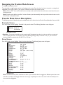
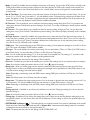
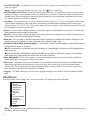
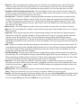
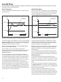
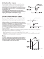
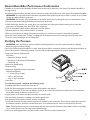
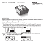
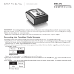
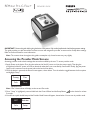
REMstar Pro C-Flex +
PROVIDER GUIDE
IMPORTANT! Remove this guide before giving the device to the patient. Only medical professionals should adjust pressure settings.
This guide provides you with instructions on how to access and navigate the provider screens used to modify device settings.
Refer to the User Manual for more information.
Note: The screens shown throughout this guide are examples only. Actual screens may vary slightly.
Accessing the Provider Mode Screens
Accessing provider mode unlocks settings that cannot be modified by the user. To access provider mode:
1. Supply Power to the device. First, plug the socket end of the AC power cord into the power supply. Then plug the
pronged end of the AC power cord into an electrical outlet that is not controlled by a wall switch. Finally, plug the power
supply cord’s connector into the power inlet on the back of the device.
2. Once the device is powered, the Home Screen appears, shown below. Turn the wheel to toggle between the four options
and highlight “Setup”.
Therapy
Flex
Info
Setup
EXIT
Reminder
Info
Setup
Home Screen
Note: “Flex” shown above will display as the current Flex mode.
3. Once “ Setup” is highlighted, press and hold both the Control Wheel and the Ramp Button
on the device for at least
5 seconds.
4. You will hear a quick double beep and the Provider Mode Screen will appear, shown below. You are now in provider mode.
Provider Screen
-1-
Navigating the Provider Mode Screens
To navigate these display screens:
Turn the wheel to toggle between options and settings on the screen. Press the wheel to choose an option or setting that is
highlighted. If you choose “Back” on any screen, it will take you back to the previous screen.
Note: Choose “EXIT” from the Provider Screen to exit provider mode and the device will return to the Home Screen in
the patient mode.
Note: Provider mode will time out after 1 minute of inactivity and automatically exit the provider mode and return to the
Home Screen in the patient mode.
Provider Mode Screen Descriptions
The following sections will describe the options available under the 3 choices from the Provider Screen (Reminder, Setup, and Info).
Reminder Screen
Reminder
From the Provider screen, highlight “Reminder” and press the wheel. The following Reminder screen will appear.
Back
Reminder off 30 90
180 270 365
Reminder Screen
• Reminder - You can set a reminder on this screen that will let patients know when it is time to perform a certain task,
such as replacing the mask. You can select one of the following settings: Off (no reminder is set), or you can set the
device to display a reminder after 90, 180, 270, or 365 days.
Setup Screen
Setup
From the Provider screen, highlight “Setup” and press the wheel. The following Setup screen will appear.
Back
Mode
Min A-Trial Days
A-Trial max
A-Trial min
A-Check Pressure
CPAP pres
Flex type
Flex
Flex lock
Ramp time
Ramp start
Tubing type lock
Tubing type
SYSTEM ONE resistance
Lock SYSTEM ONE
SYSTEM ONE humidification
Humidifier
Auto on
Auto off
Mask alert
Humidifier LED Backlight
Show AHI/leak/PB
Silent mode
Language
Back
CPAP AutoIQ
0 (3 - 30)
(Auto min) - 20.0
4.0 - (Auto max)
90% (4.0 - 20.0)
4.0 - 20.0
none C-Flex (C-Flex+ or A-Flex)
1 2 3
on off
0:00 - 0:45
4.0 - (CPAP pres)
on off
15 22
0 X1 X2 X3 X4 X5
on off
on off
0 1 2 3 4 5
on off
on off
on off
on off
on off
on off
EN ES
Setup Screen
Note: The screen will only show a few lines at a time. As you rotate the wheel to toggle over different options the screen
will slide up and down accordingly. If the text is too long to completely fit on the screen, it will scroll horizontally across
the screen when highlighted.
-2-
• Mode - If AutoIQ is available, this screen displays the therapy mode setting. You can select CPAP mode or AutoIQ mode.
CPAP mode provides one level of output pressure for the entire duration in CPAP mode. AutoIQ mode consists of an
Auto-Trial phase and an Auto-Check phase. Refer to the “AutoIQ Mode” section of this guide for complete details on
AutoIQ mode.
• Min A-Trial Days - This screen allows you to adjust the duration of the Auto-Trial phase in number of days. You can set
this to “0” or “3 to 30” days. If you select “0”, you will disable the Auto-Trial phase and go straight into the Auto-Check
phase. The default is 7 days. The number of usage days that have elapsed will be deducted from the 30 day maximum for
the device. This screen only displays if AutoIQ mode is available and enabled.
• A-Trial max - This screen allows you to modify the maximum pressure setting during Auto-Trial. You can adjust this
setting from the Auto-Trial Minimum pressure setting to 20 cm H2O. This screen only displays if AutoIQ mode is available
and enabled.
• A-Trial min - This screen allows you to modify the minimum pressure setting during Auto-Trial. You can adjust this
setting from 4 cm H2O to the Auto-Trial Maximum pressure setting. This screen only displays if AutoIQ mode is available
and enabled.
• A-Check Pressure - If AutoIQ is available, this screen allows you to adjust the Auto-Check phase starting pressure. If
Auto-Trial phase is enabled, you can choose the 90% pressure setting determined from Auto-Trial, or you can adjust this
setting from 4 to 20 cm H2O. If Auto-Trial phase is disabled, this screen allows you to only adjust the pressure setting
from 4 to 20 cm H2O if AutoIQ mode is enabled.
• CPAP pres - This screen displays the current CPAP pressure setting. You can adjust the setting from 4 cm H2O to 20 cm
H2O. This screen only displays if CPAP mode is enabled.
• Flex type - This screen displays the comfort mode setting. You can select None, C-Flex, or C-Flex+ (if in CPAP mode or
Auto-Check phase). You can select None, C-Flex, or A-Flex (if in Auto-Trial phase).
• Flex - You can modify the Flex setting (1, 2 or 3) on this screen if you enabled Flex. The setting of “1” provides a small
amount of pressure relief, with higher numbers providing additional relief.
Note: The patient also has access to this setting, if Flex is enabled.
• Flex lock - If available on your device, this enables you to lock the Flex setting if you do not want the patient to change it.
Note: If you lock this setting, the patient will see a “lock” icon ( ) next to the setting.
• Ramp time - When you set the ramp time, the device increases the CPAP pressure from the value set on the Ramp
Starting Pressure screen to the CPAP pressure setting over the length of time specified here. If the CPAP pressure is set
to 4 (the minimum setting), this screen will not display.
Note: Depending on the therapy mode, the CPAP pressure setting (CPAP pres) could also be A-Trial min or A-Check
Pressure.
Note: If the Ramp time is set to 0, Ramp start will not display.
• Ramp start - This displays the ramp starting pressure. You can increase or decrease the ramp starting pressure in 0.5 cm
H2O increments. This is only available if Ramp time has been set to >0 and CPAP pressure >4 cm H2O.
Note: Depending on the therapy mode, the CPAP pressure setting (CPAP pres) could also be A-Trial min or A-Check
Pressure.
• Tubing type lock - If available on your device, this enables you to lock the Tubing type setting if you do not want the
patient to change it.
Note: If you lock this setting, the patient will see a “lock” icon ( ) next to the setting.
• Tubing type - If available on your device, this setting allows you to select the correct size diameter tubing that you are
using with the device. You can choose either (22) for the Respironics 22 mm tubing, or (15) for the optional Respironics
15 mm tubing.
• SYSTEM ONE resistance (
) - This setting allows you to adjust the level of air pressure relief based on the specific
Respironics mask. Each Respironics mask may have a “System One” resistance control setting. System One resistance
compensation can be turned off by choosing the setting “0”.
Note: The patient also has access to this setting, if Lock SYSTEM ONE is off.
-3-
• Lock SYSTEM ONE - This enables you to lock the “System One” resistance control setting if you do not want the
patient to change it.
Note: If you lock this setting, the patient will see a “lock” icon ( ) next to the setting.
• SYSTEM ONE humidification - System One humidity control maintains a consistent mask humidity by monitoring and
adjusting for changes in room temperature and room humidity. You can enable or disable this feature. If the System One
humidity control has been disabled, the classic style of basic temperature controlled heated humidification will be used.
This will only display if the humidifier is attached.
• Humidifier - This setting allows you to choose the desired humidity setting: 0, 1, 2, 3, 4 or 5. If the System One humidity
control has been disabled, the classic style of basic temperature controlled heated humidification will be used and the
display will show: 0, C1, C2, C3, C4 or C5 for these settings. This will only display if the humidifier is attached. Please refer
to the humidifier manual if using a humidifier.
• Auto on - You can enable or disable this feature if you want the device to automatically turn the airflow on whenever the
patient applies the interface (mask) to their airway.
• Auto off - You can enable or disable this feature if you want the device to automatically turn the airflow off whenever the
patient removes the interface (mask) from their airway.
• Mask alert - You can enable or disable the mask alert setting. If this feature is enabled, the mask alert will appear on the
display screen when a significant mask leak is detected, and an audible alert will sound.
• Humidifier LED Backlight (Ramp Backlight) - You can enable or disable the LED backlight for the humidifier number
settings and Ramp button on the device.
Note: If the humidifier is not attached, this feature will display as “Ramp Backlight” and control the LED backlight for the
Ramp button only.
Note: If the Humidifier LED Backlight is enabled or disabled, the humidifier icon will always remains on (if humidifier is
attached and heat is being applied), but will dim after 30 seconds of inactivity.
• Show AHI/leak/PB - You can select whether or not the Apnea/Hypopnea index, System Leak averages, and Periodic
Breathing averages are displayed on the Patient Info screens.
• Silent mode - If available on your device, this feature can be disabled if you want the device to emit an audible indicator
(beep) during the following device operations: power on, therapy start, therapy stop, mask fit check, and humidifier
preheat mode. The device defaults to the Silent mode being enabled, meaning the device does not emit a beep during
these operations. The patient also has access to this feature.
• Language - This feature allows you to choose which language to display on the interface. The device defaults to English
(EN).
Info Screen
Info
From the Provider screen, highlight “Info” and press the wheel. The following Info screen will appear.
Back
Phone-in
Compliance VIC
Therapy hours
Blower hours
Days > 4
Large leak
AHI
Periodic breathing
Reset data
Machine hours
AutoIQ
Back
Info Screen
Note: The screen will only show a few lines at a time. As you rotate the wheel to toggle over different options the screen
will slide up and down accordingly.
-4-
• Phone-in - This screen displays the total therapy hours for the device, the total blower hours, and the total number
of days used when the sessions were greater than 4 hours since the device was last reset. This screen also displays a
compliance check number you can use to validate that the data provided to you is the data taken from this screen.
• Compliance VIC (Visual Inspection Check) - This screen displays the start day and the total number of days used
when the sessions were greater than 4 hours. This screen also displays a check code number you can use to validate that
the data provided to you is the data taken from this screen.
• Therapy hours - The device is capable of recognizing the difference between the time the patient is actually receiving
therapy and the time when the blower is simply running. This screen displays the average amount of time the patient
is actually receiving therapy on the device over a 7 day and 30 day time frame (provided the device has at least 7 or 30
days of data respectively). If the device has only 5 days of data to use for the calculation, the 5 day average value will be
seen under the 7 day display.
• Blower hours - This screen displays the number of hours that the blower has been active over the life of the device.
• Days > 4 - This screen displays the cumulative number of device therapy sessions that exceeded 4 hours over a 7 day and
30 day time frame.
• Large leak - During any given night, the device recognizes the percentage of time the patient was experiencing what it
deemed to be a large leak. Large leak is defined as the level of leak that is so large, it is no longer possible to determine
respiratory events with statistical accuracy. This screen displays the average of these individual nightly values of
percentage of time in large leak over a 7 day and 30 day time frame (provided the device has at least 7 or 30 days of data
respectively). If the device has only 5 days of data to use for the calculation, the 5 day average value will be seen under the
7 day display.
• AHI - The device accumulates individual Apnea/Hypopnea indices (AHI) for each session the patient used the device. This
screen displays the average of these individual nightly AHI values over a 7 day and 30 day time frame (provided the device
has at least 7 or 30 days of data respectively). If the device has only 5 days of data to use for the calculation, the 5 day
average value will be seen under the 7 day display.
• Periodic Breathing - During any given night, the device recognizes the percentage of time the patient was experiencing
period breathing. This screen displays the average of these individual nightly values of periodic breathing over a 7 day and
30 day time frame (provided the device has at least 7 or 30 days of data respectively). If the device has only 5 days of data
to use for the calculation, the 5 day average value will be seen under the 7 day display.
• Reset data - This screen allows you to erase all 7 and 30 day averages, compliance data, therapy hours and patient
information on the device. Make sure that “Reset data” is highlighted on the info screen. Press and hold both the control
wheel and the ramp button
for at least 5 seconds. The device will beep once signifying that the data has been reset.
Note: Machine hours are not erased.
• Machine hours - This screen displays the amount of time that the machine has been active over the life of the device.
Note: Therapy hours and blower hours can be reset for new patients. Machine hours are not erased.
• AutoIQ - If the device is in the Auto-Trial phase of AutoIQ mode, this screen displays Days: 00/00 (accumulated trial days
/ selected trial days) and Trial Days: 00 (available trial days). If the device is in the Auto-Check phase of AutoIQ mode,
this screen displays 00.0 (pressure level) and 00/30 (hours used / 30 hours).
-5-
AutoIQ Mode
If AutoIQ mode is available, the device is capable of providing a two-phase therapy approach that is comprised of an AutoTrial phase and an Auto-Check phase.
The device will deliver a modified version of Auto-CPAP therapy
which still reacts to patient events but requires a longer duration
of time to elapse before adjustments are made and is limited in
how much the pressure can be adjusted over time.
Auto-Trial
Delivered Pressure
Pressure
Auto-Check phase
The device will deliver Auto-CPAP therapy for a settable number of
days of patient use.
Pressure
Auto-Trial phase
Auto-Check
Delivered Pressure
20 cm H2O
A-Trial Max
+3 cm H2O
A-Check Pressure
-3 cm H2O
A-Trial Min
4 cm H2O
Min A-Trial Days
Time
Sample Auto-Trial Graph
Available comfort features in Auto-Trial: C-Flex and A-Flex
The Auto-Trial phase can be enabled in order to provide Auto-CPAP
therapy for a settable number of days of patient use (set through the
Min A-Trial Days setting). This setting is limited to a maximum of
30 days and must have a minimum of 3 days.
Additional settings include minimum pressure (A-Trial min) and
maximum pressure (A-Trial max).
Upon completion of the Auto-Trial phase, the device will
automatically transition to the Auto-Check phase the next time the
blower is turned on, starting at the Auto-Check phase pressure
(A-Check Pressure).
A minimum of 12 hours of use in Auto-Trial phase, including 4
hours of consecutive use in the last 7 days of Auto-Trial, is needed
to establish the 90% Pressure value (dotted line in sample graph) to
be used in the Auto-Check phase. The device will transition from
Auto-Trial into Auto-Check phase only after this occurs, in addition
to completing the provider-specified duration in Auto-Trial.
If the Auto-Trial phase is used, the number of usage days that have
elapsed will be deducted from the 30 day maximum for the device.
This is true even if the Auto-Trial phase has not completed the full
duration established by the Min A-Trial Day setting. (Example: If 5
days of Auto-Trial have been completed, a new Auto-Trial phase can
only be enabled for a maximum of 25 days.)
-6-
30 Hours
Time
Sample Auto-Check Graph
Available comfort features in Auto-Check: C-Flex and C-Flex+
The Auto-Check phase will deliver a modified version of AutoCPAP therapy which still reacts to patient events but requires
a longer duration before adjustments are made and is limited in
how much the pressure can be adjusted overall.
By default, the device will transition from the Auto-Trial phase to
the Auto-Check phase at a pressure level equal to the patient’s
90% Pressure (dotted line in sample graph) determined by the
Auto-Trial phase.
The Auto-Check phase can be entered following an Auto-Trial
phase or can be immediately started in the Auto-Check phase at
a provider-settable starting pressure between 4 and 20 cm H2O
(A-Check Pressure).
The device will detect patient events and adjust the output
pressure by no more than 1 cm H2O after every 30 hours of use.
The device can only adjust the pressure a maximum of 3 cm H2O
away from the starting pressure for the entire duration of AutoCheck.
If a new Auto-Trial phase is initiated after an Auto-Check phase
and A-Check Pressure is set to 90%, a new 90% baseline must
be established. This is even true if the device is immediately placed
back into the Auto-Check phase.
If an Auto-Trial phase was completed with C-Flex or A-Flex
enabled, the comfort feature setting will automatically be carried
over to the Auto-Check phase. C-Flex in the Auto-Trial Phase will
remain as C-Flex in the Auto-Check phase and A-Flex in the AutoTrial phase will transition to C-Flex+ in the Auto-Check phase.
C-Flex Comfort Feature
The device consists of a special comfort feature called C-Flex. When
C-Flex is enabled, it enhances patient comfort by providing pressure
relief during the expiratory phase of breathing. In the diagram, the
dashed line represents normal CPAP therapy in comparison to the bold
line representing C-Flex. C-Flex levels of 1, 2, or 3 progressively reflect
increased pressure relief.
C-Flex pressure relief is determined by the C-Flex setting and the
amount of patient flow. C-Flex returns to the set pressure by the end of
exhalation, when the airway is most vulnerable to closure.
Note: The patient also has access to this setting, if C-Flex is enabled.
A-Flex (C-Flex+) Comfort Feature
The device consists of a special comfort feature called A-Flex if in AutoExhalation starts and
pressure level decreases
Trial phase (or C-Flex+ if in CPAP mode or Auto-Check phase). When
A-Flex (C-Flex+) is enabled, it enhances patient comfort in three ways:
Therapy
1) by smoothing the transition between the end of inhalation and the
Pressure
beginning of exhalation, 2) by providing significant pressure relief during
the beginning of exhalation, and 3) by reaching an end exhalation pressure
1
A-Flex Levels
of no more than 2 cm H2O below the high point of inspiration.
2
(1, 2 and 3)
In the diagram, the dashed line represents CPAP pressure in comparison
3
to the bold line representing A-Flex (C-Flex+). A-Flex (C-Flex+) levels
Exhalation
Inhalation
of 1, 2, or 3 progressively reflect increased pressure relief during the
beginning of exhalation.
With A-Flex (C-Flex+), the level of pressure relief at the beginning of exhalation is determined by the A-Flex (C-Flex+)
setting and the amount of patient flow in any one breath.
Note: The patient also has access to this setting, if A-Flex (C-Flex+) is enabled.
Note: A-Flex (C-Flex+) transitions from no A-Flex (C-Flex+) at 4.0 cm H2O to full A-Flex (C-Flex+) at 6 cm H2O.
A-Flex (C-Flex+) is top limited at 20.0 cm H2O pressure.
Time
Ramp
The device is equipped with a linear ramp feature that allows patients to
reduce the pressure and then gradually increase (ramp) the pressure to
the prescription pressure setting so they can fall asleep more comfortably.
The diagram illustrates how the ramp feature works.
-7-
Event Definitions
The REMstar Pro C-Flex+ monitors breathing and detects the following events.
Event
Definition
Obstructed Airway
Apnea / Clear
Airway Apnea
Detection
An apnea is detected when there is an 80% reduction in airflow from baseline for at least 10 seconds or if there is no
airflow detected for 10 seconds.
RERA
Detection
RERA (Respiratory effort-related arousal) is defined as an arousal from sleep that follows a 10 second or longer
sequence of breaths that are characterized by increasing respiratory effort, but which does not meet criteria for an
apnea or hypopnea. Snoring, though usually associated with this condition need not be present. The RERA algorithm
monitors for a sequence of breaths that exhibit both a subtle reduction in airflow and progressive flow limitation. If
this breath sequence is terminated by a sudden increase in airflow along with the absence of flow limitation, and the
event does not meet the conditions for an apnea or hypopnea, a RERA is indicated.
Periodic Breathing
A persistent waning and waxing breathing pattern which repeats itself between 30 and 100 seconds. The nadir of
the breathing pattern is characterized by at least a 40% reduction in airflow from an established baseline flow. The
pattern must be present for several minutes before it can be identified as periodic breathing.
During the apnea, one or more pressure test pulses are delivered by the device. The device evaluates the response of
the patient to the test pulse(s) and assesses whether the apnea has occurred while the patient has a clear airway or
an obstructed airway. The airway is determined to be clear if the pressure test pulse generates a significant amount of
flow; otherwise the airway is determined to be obstructed.
No therapy adjustments are made in response to periodic breathing.
Flow Limitation
Detection
The device looks for relative changes in the peak, flatness, roundness, or shape (skewness) of the inspiratory portion
of the airflow waveform. These changes are observed both over a short period of time (groups of 4 breaths) and
over a long period of time (several minutes). Statistical measures are used to help minimize false event detection
while allowing the device to be sensitive to even small changes.
Hypopnea
Detection
A hypopnea is detected when there is an approximately 40% reduction in airflow from baseline for at least 10
seconds.
Snore
Detection
Vibratory snore is detected when a specific frequency is detected during the inspiratory portion of the patient’s
breath.Vibratory snore is disabled at pressures greater than 16 cm H2O.
Cleaning for Multiple Users
WARNING: If you are using the device on multiple users, discard and replace the bacteria filter each time the device is
used on a different person.
If you are using the device on multiple users, complete the following steps to clean the device before each new user.
1. Unplug the device before cleaning.
2. Clean the outside of the device only. Use a cloth with one of the following cleaning agents to clean the exterior of the
device:
• Mild Detergent
• 70% Isopropyl Alcohol
• DisCide Towelettes
• 10% Chlorine Bleach solution
3. Allow the device to dry completely before plugging in the power cord.
-8-
Heated Humidifier Performance Confirmation
If available on your device, the Humidifier Preheat mode can be used to determine if the System One Heated Humidifier is
working properly.
The following steps should be followed if there is a desire to confirm the performance of the System One Heated Humidifier.
WARNING: It is important to follow the exact steps below when performing this test in order to ensure no injury. Read
all steps first before performing this test.
WARNING: Do not place your hand directly on the heater plate at any time during this test as it could result in a burn.
1.Disconnect the patient tubing (if attached) and remove the water tank.
2.While the therapy device is not running, place your hand above the heater plate (without touching it) to assess the
temperature of the heater plate when off for later comparison.
3.Turn on Humidifier Preheat mode as described in the User Manual.
4.Allow the device to run in preheat mode for 30 seconds.
5.Place your hand above the heater plate (without touching it) to confirm an increase in heater plate temperature.
6.Press the control wheel while “Therapy” is highlighted on the Home screen to enter therapy and end preheat mode.
7.Press the control wheel again to turn off therapy.
Verifying the Pressure
WARNING: If the device fails to perform within the stated specifications, have the system serviced by a qualified
Respironics-approved service facility.
If part of your patient setup procedure is to verify actual pressure with a manometer, please use the following instructions to
ensure that the device is functioning properly. You will need the following equipment to verify the pressure:
• Respironics Pressure Calibration Kit
Kit Includes:
• Respironics Whisper Swivel II
• Respironics O2 Enrichment Final Assembly
• Closed end cap
• Respironics flexible tubing
• Pressure tubing
• Respironics Digital Manometer or equivalent
Minimum Specifications:
• 0 - 25 cm H2O (or better)
• ± 0.3 cm H2O accuracy
• ± 0.1 cm H2O resolution
• Foam filter
To verify the pressure, complete the following steps:
1. Install the foam filter into the back of the device.
2. With the device unplugged, connect the system as illustrated in the diagram.
3. Turn the manometer on. If it does not display a reading of zero, adjust the manometer to calibrate it. If the manometer
has variable settings for devices, set it to cm H2O.
4. Supply power to the device then place the device in provider mode.
5. Set the therapy parameters according to the patient specific data.
6. Set the device to the specific pressure value for the patient.
7. Verify that the pressure setting matches the pressure displayed on the manometer. If the pressure setting does not match
the measured value for the device, contact Respironics or an authorized service center to have the device serviced.
Note: Output pressures may vary at local altitude and barometric pressure. Because of these factors, devices may slightly
vary in output pressure over the range of the altitude settings.
8. Set up the remaining parameters and exit provider mode. The unit is ready for patient use.
-9-
EMC Information
Guidance and Manufacturer’s Declaration - Electromagnetic Emissions – This device is intended for use in the electromagnetic
environment specified below. The user of this device should make sure it is used in such an environment.
Emissions Test
Compliance
Electromagnetic Environment - Guidance
RF emissions
CISPR 11
Group 1
The device uses RF energy only for its internal function. Therefore, its RF emissions
are very low and are not likely to cause any interference in nearby electronic
equipment.
RF emissions
CISPR 11
Class B
The device is suitable for use in all establishments, including domestic establishments
and those directly connected to the public low-voltage power supply network.
Harmonic emissions
IEC 61000-3-2
Class A
Voltage fluctuations/Flicker emissions
IEC 61000-3-3
Complies
Guidance and Manufacturer’s Declaration - Electromagnetic Immunity – This device is intended for use in the electromagnetic
environment specified below. The user of this device should make sure it is used in such an environment.
Immunity Test
Electrostatic
Discharge (ESD)
IEC 60601 Test
Level
Compliance Level
Electromagnetic Environment Guidance
±6 kV contact
±6 kV contact
Floors should be wood, concrete or ceramic tile.
If floors are covered with synthetic material, the
relative humidity should be at least 30%.
±8 kV air
±8 kV air
±2 kV for power supply lines
±2 kV for supply mains
±1 kV for input-output lines
±1 kV for input/output lines
±1 kV differential mode
±1 kV differential mode
±2 kV common mode
±2 kV for common mode
<5% UT
(>95% dip in UT) for
0.5 cycle
40% UT
(60% dip in UT) for
5 cycles
70% UT (30% dip in
UT) for 25 cycles
<5% UT (>95% dip in UT) for
5 sec
<5% UT
(>95% dip in UT) for
0.5 cycle
40% UT
(60% dip in UT) for 5 cycles
70% UT (30% dip in UT) for
25 cycles
<5% UT (>95% dip in UT) for
5 sec
Mains power quality should be that of a typical
home or hospital environment. If the user of
the device requires continued operation during
power mains interruptions, it is recommended
that the device be powered from an
uninterruptible power supply or a battery.
3 A/m
3 A/m
Power frequency magnetic fields should be at
levels characteristic of a typical location in a
typical hospital or home environment.
IEC 61000-4-2
Electrical fast
Transient/burst
Mains power quality should be that of a typical
home or hospital environment.
IEC 61000-4-4
Surge
IEC 61000-4-5
Voltage dips, short
interruptions and voltage
variations on power supply
input lines
IEC 61000-4-11
Power frequency (50/60 Hz)
magnetic field
IEC 61000-4-8
NOTE: UT is the a.c. mains voltage prior to application of the test level.
- 10 -
Mains power quality should be that of a typical
home or hospital environment.
Guidance and Manufacturer’s Declaration - Electromagnetic Immunity – This device is intended for use in the electromagnetic
environment specified below. The user of this device should make sure it is used in such an environment.
Immunity Test
IEC 60601 Test Level
Compliance Level
Electromagnetic Environment -Guidance
Portable and mobile RF communications equipment should be
used no closer to any part of the device, including cables, than the
recommended separation distance calculated from the equation
applicable to the frequency of the transmitter.
Conducted RF
IEC 61000-4-6
3 Vrms
150 kHz to 80 MHz
Radiated RF
IEC 61000-4-3
3 V/m
80 MHz to 2.5 GHz
3 Vrms
Recommended separation distance
d = 1.2
d = 1.2
d = 2.3
80 MHz to 800 MHz
800 MHz to 2.5 GHz
3 V/m
where P is the maximum output power rating of the transmitter in
watts (W) according to the transmitter manufacturer and d is the
recommended separation distance in meters (m).
Field strengths from fixed RF transmitters, as determined by an
electromagnetic site surveya, should be less than the compliance level in
each frequency range.b
Interference may occur in the vicinity of equipment marked with the
following symbol:
NOTE 1 At 80 MHz and 800 MHz, the higher frequency range applies.
NOTE 2 These guidelines may not apply in all situations. Electromagnetic propagation is affected by absorption and reflection from structures,
objects, and people.
a
Field strengths from fixed transmitters, such as base stations for radio (cellular/cordless) telephones and land mobile radios, amateur radio,
AM and FM radio broadcast and TV broadcast cannot be predicted theoretically with accuracy. To assess the electromagnetic environment
due to fixed RF transmitters, an electromagnetic site survey should be considered. If the measured field strength in the location in which
the device is used exceeds the applicable RF compliance level above, the device should be observed to verify normal operation. If abnormal
performance is observed, additional measures may be necessary, such as re-orienting or relocating the device.
b
Over the frequency range 150 kHz to 80 MHz, the field strengths should be less than 3 V/m.
Recommended Separation Distances between Portable and Mobile RF Communications Equipment and This Device: The device is
intended for use in an electromagnetic environment in which radiated RF disturbances are controlled. The customer or the user
of this device can help prevent electromagnetic interference by maintaining a minimum distance between portable and mobile RF
communications equipment (transmitters) and this device as recommended below, according to the maximum output power of the
communications equipment.
Rated Maximum Power
Output of Transmitter
W
Separation Distance According to Frequency of Transmitter
m
150 kHz to 80 MHz
d = 1.2
80 MHz to 800 MHz
d = 1.2
800 MHz to 2.5 GHz
d = 2.3
0.01
0.12
0.12
0.23
0.1
0.38
0.38
0.73
1
1.2
1.2
2.3
10
3.8
3.8
7.3
100
12
12
23
For transmitters rated at a maximum output power not listed above, the recommended separation distance d in meters (m) can be estimated using
the equation applicable to the frequency of the transmitter, where P is the maximum output power rating of the transmitter in watts (W) according
to the transmitter manufacturer.
Note 1: At 80 MHz and 800 MHz, the separation distance for the higher frequency range applies.
Note 2: These guidelines may not apply in all situations. Electromagnetic propagation is affected by absorption and reflection from structures,
objects, and people.
- 11 -
1058284
1057391 R04
JR 6/23/2011
EN-DOM
- 12 -