1
Chapter 2 Installation and Setup
Installation and Operation Manual
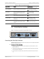
Connecting the E1/T1 Interface
The rear-panel E1/T1 connector provides interface for data input/output, clock
reference, and control signal exchange between FOM-E1/T1 and E1/T1
equipment.
A balanced E1/T1 interface terminates in an RJ-45 connector (see Appendix A for
the connector pinout).
An unbalanced E1 interface terminates in two coaxial BNC connectors, designated
as IN and OUT. IN refers to the FOM-E1/T1 input signal. OUT refers to a signal
transmitted from FOM-E1/T1 to the attached equipment.
Connecting the Alarm Relay
Connect a cable with a 9-pin, D-type, male connector to the connector marked
ALARMS (see Appendix A for the connector pinout).
2.7
Warning
Connecting to Power
Before connecting this unit to a power outlet and connecting or disconnecting
any other cable, the protective earth terminals of this unit must be connected to
the protective ground conductor of the mains (AC or DC) power cord. If you are
using an extension cord (power cable) make sure it is grounded as well.
Any interruption of the protective (grounding) conductor (inside or outside the
instrument) or disconnecting of the protective earth terminal can make this unit
dangerous. Intentional interruption is prohibited.
Connecting AC Power
AC power is supplied to the FOM-E1/T1 modem through a standard 3-prong
connector.
Connect AC power through the 1.5m (5 ft) standard power cable terminated by a
standard 3-prong connector. A cable is provided with the unit.
To connect AC power:
1. Connect the power cable to the power connector on the FOM-E1/T1 rear
panel.
2. Connect the power cable to the mains outlet.
The unit powers on automatically when connected to the mains.
Connecting DC Power
A special IEC 60320 adapter for connection to -48/-60 VDC power is supplied with
the unit. 24 VDC FOM-E1/T1 units have a terminal block DC inlet and an adapter
supplied with the unit.
2-4
Connecting to Power
FOM-E1/T1 Ver. 2.0