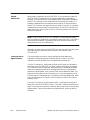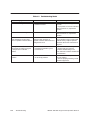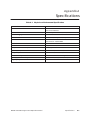
1
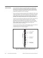
SIMATIC 505-2571 Program Port Expander User Manual Order Number: PPX:505–8131–1 Manual Assembly Number: 2806135–0001 Original Edition ! DANGER DANGER indicates an imminently hazardous situation that, if not avoided, will result in death or serious injury. DANGER is limited to the most extreme situations. ! WARNING WARNING indicates a potentially hazardous situation that, if not avoided, could result in death or serious injury, and/or property damage. ! CAUTION CAUTION indicates a potentially hazardous situation that, if not avoided, could result in minor or moderate injury, and/or damage to property. CAUTION is also used for property-damage-only accidents. Copyright 1996 by Siemens Energy & Automation, Inc. All Rights Reserved — Printed in USA Reproduction, transmission, or use of this document or contents is not permitted without express consent of Siemens Energy & Automation, Inc. All rights, including rights created by patent grant or registration of a utility model or design, are reserved. Since Siemens Energy & Automation, Inc., does not possess full access to data concerning all of the uses and applications of customer’s products, we do not assume responsibility either for customer product design or for any infringements of patents or rights of others which may result from our assistance. MANUAL PUBLICATION HISTORY SIMATIC 505-2571 Program Port Expander User Manual Order Manual Number: PPX:505-8131-1 Refer to this history in all correspondence and/or discussion about this manual. Event Date Description Original Issue 04/96 Original Issue 2806135–0001) LIST OF EFFECTIVE PAGES Pages Cover/Copyright History/Effective Pages iii — vii 1-1 — 1-5 2-1 — 2-6 3-1 — 3-3 4-1 — 4-4 A-1 — A-1 Registration Description Original Original Original Original Original Original Original Original Original Pages Description Contents Chapter 1 PPX:505-2571 Module Description Module Features . . . . . . . . . . . . . . . . . . . . . . . . . . . . . . . . . . . . . . . . . . . . . . . . . . . . . . . . . . . . . . . . . . 1-2 Chapter 2 2.1 Installing the Module Getting Started . . . . . . . . . . . . . . . . . . . . . . . . . . . . . . . . . . . . . . . . . . . . . . . . . . . . . . . . . . . . . . . . . 2-2 Installation Planning . . . . . . . . . . . . . . . . . . . . . . . . . . . . . . . . . . . . . . . . . . . . . . . . . . . . . . . . . . . . . Unpacking the Module . . . . . . . . . . . . . . . . . . . . . . . . . . . . . . . . . . . . . . . . . . . . . . . . . . . . . . . . . . Configuring the Module . . . . . . . . . . . . . . . . . . . . . . . . . . . . . . . . . . . . . . . . . . . . . . . . . . . . . . . . . Inserting the Module into the I/O Base . . . . . . . . . . . . . . . . . . . . . . . . . . . . . . . . . . . . . . . . . . . Connecting Operator Interface Devices . . . . . . . . . . . . . . . . . . . . . . . . . . . . . . . . . . . . . . . . . Powering Up the Module . . . . . . . . . . . . . . . . . . . . . . . . . . . . . . . . . . . . . . . . . . . . . . . . . . . . . . . . Checking PLC Login . . . . . . . . . . . . . . . . . . . . . . . . . . . . . . . . . . . . . . . . . . . . . . . . . . . . . . . . . . . . 2-2 2-2 2-3 2-4 2-4 2-5 2-5 Chapter 3 Module Operation Effect of Controller Scan Time . . . . . . . . . . . . . . . . . . . . . . . . . . . . . . . . . . . . . . . . . . . . . . . . . . . Chapter 4 Troubleshooting Module Malfunction . . . . . . . . . . . . . . . . . . . . . . . . . . . . . . . . . . . . . . . . . . . . . . . . . . . . . . . . . . . . Communications Signal Problems . . . . . . . . . . . . . . . . . . . . . . . . . . . . . . . . . . . . . . . . . . . . . . . . Module Response Problems . . . . . . . . . . . . . . . . . . . . . . . . . . . . . . . . . . . . . . . . . . . . . . . . . . . . . Baud Rate Mismatch . . . . . . . . . . . . . . . . . . . . . . . . . . . . . . . . . . . . . . . . . . . . . . . . . . . . . . . . . . . . Hardware Handshaking Error . . . . . . . . . . . . . . . . . . . . . . . . . . . . . . . . . . . . . . . . . . . . . . . . . . . . Protocol Problems . . . . . . . . . . . . . . . . . . . . . . . . . . . . . . . . . . . . . . . . . . . . . . . . . . . . . . . . . . . . . . Appendix A 3-2 Specifications . . . . . . . . . . . . . . . . . . . . . . . . . . . . . . . . . . . . . . . . . Contents 4-2 4-2 4-3 4-3 4-3 4-3 A-1 iii List of Figures 1-1 PPX:505-2571 Program Port Expander Module . . . . . . . . . . . . . . . . . . . . . . . . . . . . . . . . . . . . . . . 1-2 Process Monitoring Application Using PCs . . . . . . . . . . . . . . . . . . . . . . . . . . . . . . . . . . . . . . . . . . 1-3 Attaching a Lap Top PC . . . . . . . . . . . . . . . . . . . . . . . . . . . . . . . . . . . . . . . . . . . . . . . . . . . . . . . . . . . 1-2 1-4 1-5 2-1 Location of Baud Rate Switches . . . . . . . . . . . . . . . . . . . . . . . . . . . . . . . . . . . . . . . . . . . . . . . . . . . 2-2 Connector Pin-Out Description . . . . . . . . . . . . . . . . . . . . . . . . . . . . . . . . . . . . . . . . . . . . . . . . . . . . . 2-3 Sample I/O Configuration Chart . . . . . . . . . . . . . . . . . . . . . . . . . . . . . . . . . . . . . . . . . . . . . . . . . . . 2-3 2-4 2-5 iv Contents List of Tables 2-1 Baud Rate Switch Settings . . . . . . . . . . . . . . . . . . . . . . . . . . . . . . . . . . . . . . . . . . . . . . . . . . . . . . . . . 2-3 4-1 Troubleshooting Matrix . . . . . . . . . . . . . . . . . . . . . . . . . . . . . . . . . . . . . . . . . . . . . . . . . . . . . . . . . . . . . 4-4 A-1 Physical and Environmental Specifications . . . . . . . . . . . . . . . . . . . . . . . . . . . . . . . . . . . . . . . . . A-1 Contents v Preface This user manual provides installation and operation instructions for the SIMATIC 505-2571 Program Port Expander Module for Series 505 programmable controllers. We assume you are familiar with the operation of Series 505 programmable controllers. Refer to the appropriate SIMATIC user documentation for specific information on the controllers and I/O modules. This user manual is organized as follows: Manual Title • Chapter 1 provides a description of the module. • Chapter 2 covers installation and checkout. • Chapter 3 describes operation of the module. • Chapter 4 discusses troubleshooting. Preface vii Chapter 1 PPX:505-2571 Module Description Module Features . . . . . . . . . . . . . . . . . . . . . . . . . . . . . . . . . . . . . . . . . . . . . . . . . . . . . . . . . . . . . . . . . . 1-2 SIMATIC 505-2571 Program Port Expander Manual 505–2571 Module Description 1-1 Module Features The PPX:505-2571 Program Port Expander Module is a member of the communication family of I/O modules for the Series 505 programmable controllers. The PPX:505-2571 is a single-wide, Special Function module that provides four additional communications ports that function like the program port provided on the CPU front panel. Ports 1 and 2 have an electrical interface that is a subset of RS–232C using a male DB9 connector. Ports 3 and 4 provide an RS–422 electrical interface using a female DB9 connector. Both interfaces have been chosen to match the programming ports provided on the SIMATIC 545 programmable controller. Thus, commonly used cables can be used with the PPX:505-2571. The ports may be configured to support baud rates of 1200, 2400, 9600, and 19,200. All four ports may be used simultaneously with a combined aggregate baud rate of 38,400 baud (for example, all four ports at 9600 baud). The PPX:505-2571 has two communication indicators for each port, one for transmit and one for receive. These indicators light when communications activity is taking place. The red ”Active” indicator is used to indicate module status. The indicator is illuminated when the module is functioning properly. See the troubleshooting section for additional details. Active Indicator Port Activity Indicators RS-232 Ports (Male DB9) RS-422 Ports Female DB9) 505-2571 Figure 1-1 PPX:505-2571 Program Port Expander Module 1-2 505–2571 Module Description SIMATIC 505-2571 Program Port Expander Manual As control systems become more complex and dispersed, the demand for attaching serial devices has increased. Serial devices are typically used to provide operator interface, to run supervisory control and monitoring packages, and to facilitate controller programming support. Most Series 505 controllers today are equipped with two serial ports to accommodate the minimum requirement. However, these ports can be consumed with the supervisory control package and one operator device. Some controllers, like the SIMATIC 525, provide only an RS-232 port, limiting reliable communications to about 50 feet at higher baud rates. The PPX:505-2571 provides two additional RS-232 ports and 2 additional RS-422 ports in addition to the standard controller ports. These additional ports may be used to attach various types of serial devices which conform to the Non–Intelligent Terminal Protocol (NITP). Devices requiring the Transparent Byte Protocol (TBP) must be connected to the CPU or the RBC serial port. The simplest of these types of devices are COROS TD/OP operator panels. These operator interfaces provide for direct access to controller memory locations for read and/or write capability through an RS-422 direct connection. Devices attached through the RS-422 interface may be located up to 4000 feet away. SIMATIC 505-2571 Program Port Expander Manual 505–2571 Module Description 1-3 More sophisticated applications may require the monitoring of a large number of variables in the controller. There are a number of third party applications available that may be used to access data from the controller and perform statistical process control, trending, report generation and other applications. These third party applications typically run on a PC or other platform but most all of them communicate to the controller directly through the program port. Often times there are multiple nodes that need to be connected to the controller. With the PPX:505-2571 this may easily be accomplished. See Figure 1-2. PC Compatible PPX:505-2571 Module PC Compatible Figure 1-2 Process Monitoring Application Using PCs 1-4 505–2571 Module Description SIMATIC 505-2571 Program Port Expander Manual Using a notebook PC running the SIMATIC TISOFTapplication, a maintenance engineer can easily make changes in the controller program or adjust timer and/or drum preset values. During start up conditions a PC may be attached to a serial port to aid in the debugging process. The additional ports on the PPX:505-2571 make it possible to access locally the controller. See Figure 1-3. Lap Top PPX:505-2571 Module Figure 1-3 Attaching a Lap Top PC SIMATIC 505-2571 Program Port Expander Manual 505–2571 Module Description 1-5 Chapter 2 Installing the Module 2.1 Getting Started . . . . . . . . . . . . . . . . . . . . . . . . . . . . . . . . . . . . . . . . . . . . . . . . . . . . . . . . . . . . . . . . . 2-2 Installation Planning . . . . . . . . . . . . . . . . . . . . . . . . . . . . . . . . . . . . . . . . . . . . . . . . . . . . . . . . . . . . . Unpacking the Module . . . . . . . . . . . . . . . . . . . . . . . . . . . . . . . . . . . . . . . . . . . . . . . . . . . . . . . . . . Configuring the Module . . . . . . . . . . . . . . . . . . . . . . . . . . . . . . . . . . . . . . . . . . . . . . . . . . . . . . . . . Inserting the Module into the I/O Base . . . . . . . . . . . . . . . . . . . . . . . . . . . . . . . . . . . . . . . . . . . Connecting Operator Interface Devices . . . . . . . . . . . . . . . . . . . . . . . . . . . . . . . . . . . . . . . . . Powering Up the Module . . . . . . . . . . . . . . . . . . . . . . . . . . . . . . . . . . . . . . . . . . . . . . . . . . . . . . . . Checking PLC Login . . . . . . . . . . . . . . . . . . . . . . . . . . . . . . . . . . . . . . . . . . . . . . . . . . . . . . . . . . . . 2-2 2-2 2-3 2-4 2-4 2-5 2-5 SIMATIC 505-2571 Program Port Expander Manual Installing the Module 2-1 2.1 Getting Started The installation of the PPX:505-2571 Programming Port Expander Module consists of the following steps: Installation Planning 1. Planning the installation. 2. Installing the module into the I/O base. 3. Connecting operator interface devices to the module communication port. 4. Checking the module operation. The PPX:505-2571 requires 5 watts of +5VDC power. Before inserting the module into the I/O base, ensure that the power supply capacity is not exceeded. RS–232 communications cables should be no longer than 50 feet in length. RS–422 cables may extend up to 4000 feet at 9600 baud. Unpacking the Module Open the shipping carton and remove the special anti-static bag which contains the module. ! CAUTION The components on the PPX:505-2571 module printed circuit card can be damaged by static electricity discharge. To prevent this damage, the module is shipped in a special anti-static bag. Static control precautions should be followed when removing the module from the bag, and when handling the printed circuit card during configuration. After discharging any static build–up, remove the module from the anti-static bag. Do not discard the static bag. Always use this bag for protection against static damage when the module is not inserted into the I/O base. 2-2 Installing the Module SIMATIC 505-2571 Program Port Expander Manual Configuring the Module The baud rates for each port may be individually set via DIP switches. In addition, for the RS–232 ports (1 and 2) you can enable or disable hardware handshaking. The PPX:505-2571 is shipped with all DIP switches in the OFF position. This corresponds to a baud rate of 9600 and hardware handshaking DISABLED for ports 1 and 2. NOTE: Unless the device you are attaching explicitly requires hardware handshaking, you should leave hardware handshaking DISABLED. See Table 2-1 and Figure 2-1 for the location and settings of the switches. All other communications parameters are fixed: Data Bits = 7, Parity = Odd, Stop Bits = 1. NOTE: Switch position 3 is not used for ports 3 and 4, since RS–422 does not support hardware handshaking. For ports 3 and 4, switch 3 is ignored and should be left in the OFF position. For all ports, switch positions 4 through 8 are reserved for future use and should be left in the OFF position. Table 2-1 Baud Rate Switch Settings Baud Rate Switch 1 Position Switch 2 Position Hardware Handshaking Switch 3 Position 1200 On On Disabled Off 2400 On Off Enabled On 9600 Off Off 19200 Off On On Off Not Used (Set to Off) Hardware Handshaking Baud Rate Example: Dipswitch #1, #2 and #3 are shown in the “OFF” position for Port 1 indicating a baud rate of 9600 and hardware handshaking disabled. Figure 2-1 Location of Baud Rate Switches SIMATIC 505-2571 Program Port Expander Manual Installing the Module 2-3 Getting Started (continued) Inserting the Module into the I/O Base Hold the top and bottom of the bezel and slide the module carefully into the slot, pushing it all the way into the base. If you have inserted the module correctly, you will feel a slight increase in resistance as the module mates with the base backplane connector. Once the module is fully seated in the slot, tighten the captive screws at the top and bottom to hold the module in place. To remove the module from the I/O base, loosen the captive screws, then remove the module. Take care not to damage the connector at the back of the module when inserting or removing the module. Connecting Operator Interface Devices Serial communications cables are used to connect Operator Interface devices to the ports of the PPX:505-2571. Port 1 and 2 provide a subset of the RS–232C electrical interface. Cables for the RS-232 ports should be no longer than 50 feet. Ports 3 and 4 provide an RS-422 electrical interface. RS–422 cables may be up to 4000 feet in length. The port connections on the PPX:505-2571 have been designed to accept commonly used serial cables. The pin-outs on both the RS–232 ports and the RS–422 ports match those found on the Series 545 controller. In addition, the RS–232 connector matches those found on IBM PC/AT machines. You can purchase standard cables from Siemens Energy & Automation, Inc. which connect the PPX:505-2571 to the IBM-PC by ordering part number 2587693–8011. Should you choose to construct your own custom cables, refer to Figure 2-2 for connector pin-out description. RS-232 Ports 1 & 2 Sheild Male PIN # RX 2 TX 3 Signal GND 5 1 6 9 5 505–2571 Connector Ports 1 & 2 RTS 7 CTS 8 DCD 1 DB9 RS-232 DTR 4 DSR 6 RS-422 Ports 3 & 4 Female Sheild PIN # TX+ TX– RX+ RX– 1 7 5 8 1 6 9 5 505–2571 Connector Ports 3 & 4 DB9 RS-422 Figure 2-2 Connector Pin-Out Description 2-4 Installing the Module SIMATIC 505-2571 Program Port Expander Manual If you require hardware handshaking for flow control, you should refer to the device documentation for information on connecting the RTS, CTS, DCD, DTR, and DSR lines. The PPX:505-2571 RS–232 port is configured as DTE. In addition, you should set the port DIP switch position 3 to ON (see Table 2-1 and Figure 2-1). NOTE: Most common operator interface devices do not use the hardware handshaking lines; therefore, you do not need to connect them. If you DO NOT use hardware handshaking you MUST set DIP switch 3 to OFF (see Table 2-1 and Figure 2-1). Powering Up the Module First turn on the base power supply. If the diagnostics on the PPX:505-2571 detect no problems, the ACTIVE indicator will illuminate. If the indicator does not illuminate or exhibits a blinking pattern, the module has detected a component failure. For information on viewing failed module status, refer to your SIMATIC TISOFT Programming Reference Manual. See Chapter 4 of this manual for troubleshooting information. Checking PLC Login Next, check that the module is configured in the memory of the PLC. To view the PLC I/O configuration chart refer to your SIMATIC TISOFT Programming Reference Manual. See Figure 2-3. 505 I/O MODULE DEFINITION FOR CHANNEL . 1 SLOT 01 02 . . . 15 16 I/O ADDRESS BASE . . . 00 NUMBER OF BIT AND WORD I/O X Y WX WY SPECIAL FUNCTION . . . . . 0001 . . . . . . 00 . . . . 00 . . . . 02 . . . 06 . . . . . . . YES . . . . . 0000 . . . . . . 00 . . . . 00 . . . . 00 . . . 00 . . . . . . . NO . . . . . 0000 . . . . . . 00 . . . . 00 . . . . 00 . . . 00 . . . . . . . NO . . . . . 0000 . . . . . . 00 . . . . 00 . . . . 00 . . . 00 . . . . . . . NO Figure 2-3 Sample I/O Configuration Chart SIMATIC 505-2571 Program Port Expander Manual Installing the Module 2-5 Getting Started (continued) In Figure 2-3, the PPX:505-2571 module is installed into slot 1 and I/O base 0. For your particular installation, look in the chart at the slot address occupied by the module in your configuration. If the WX and WY values are the same as those shown in the example above and Special Function = YES then the module is logged into the controller memory and is ready for operation. If the line is blank or erroneous, re-check the module to ensure tthat it is firmly seated in the I/O base slot. Generate the PLC I/O configuration chart again by reading the I/O base. If still incorrect contact the Siemens Energy & Automation, Inc., Technical Services Group in the U.S.A. at 423–461–2522. In other countries, you can also contact the nearest Siemens distributor. Use the attached operator interface device(s) to send commands to the controller and validate the resulting response. If you encounter a problem, refer to Chapter 4, Troubleshooting. 2-6 Installing the Module SIMATIC 505-2571 Program Port Expander Manual Chapter 3 Module Operation Effect of Controller Scan Time . . . . . . . . . . . . . . . . . . . . . . . . . . . . . . . . . . . . . . . . . . . . . . . . . . . SIMATIC 505-2571 Program Port Expander Manual Module Operation 3-2 3-1 The PPX:505-2571 is designed to work with operator interface devices which adhere to the Non–Intelligent Terminal Protocol (NITP). Up to four supported devices may concurrently communicate with the controller. The PPX:505-2571 will provide buffering for the commands from the operator interface and responses from the controller. Commands are sent to the controller in the order they are received; no port has priority over any other port. Only one command per port can be pending at a given time; a response must be sent to the operator interface before a subsequent command will be accepted. With a few minor restrictions, the PPX:505-2571 port should function the same as the controller program port. NOTE: The ACTIVE indicator should remain on at all times after power up. Should the ACTIVE indicator go out or exhibit a blink pattern, refer to the troubleshooting section. When data is sent to a port the RCV indicator for that port should light briefly. Similarly, when data is sent from a port the XMT indicator should light briefly. This release of the PPX:505-2571 does not support Transparent Byte Protocol (TBP). In addition, the PPX:505-2571 does not support an ASCII print data stream. Effect of Controller Scan Time Because the PPX:505-2571 is a Special Function module, the controller scan time will be longer when the module is logged into the controller. The effect on scan time depends on several factors, including the type of request the controller is processing and the number of requests processed per scan. Some requests, such as a Read or Write memory location, can be processed relative quickly. Others, such as Find, consume significant controller CPU resources. The SIMATIC 545 CPU can process a maximum of eight requests per scan. It is possible for the user, via Aux 16, to set the number of requests (task codes) that are processed each scan, for a minimum of one to a maximum of eight. A lower number should normally result in a faster controller scan time; the amount of increase depends on the type of request. However, since more requests can be processed each scan, this may improve data throughput through the PPX:505-2571. 3-2 Module Operation SIMATIC 505-2571 Program Port Expander Manual The requests are processed during the discrete portion of the controller scan (refer to Chapter 1 of the SIMATIC 545/555/575 System Manual for a discussion of the timeline). Thus, the scan interval to process the requests from the PPX:505-2571 (or any other Special Function module) cannot be lengthened by manipulating the time slices, which affect only the analog portion of the scan. To maximize throughput, the PPX:505-2571 should be placed in the local base with the controller. A PPX:505-2571 module in the local base has the advantage of 8-bit parallel data transfer to the controller across the backplane. A remote I/O module must communicate with the controller via a serial data stream. A local base module also has a few milliseconds advantage because it is not subject to the remote base timing restrictions. These advantages add up to an order of magnitude improvement in local base execution time over remote base. Whether the effect on scan time is significant or not depends upon your application. If your controller is lightly loaded and/or task code requests routed through the PPX:505-2571 are simple, then you may not notice the effect at all. On the other hand, if the controller is heavily loaded, scan times are critical, and complex requests are being sent to the controller, you may have to make some trade-offs between controller performance and the time required to respond to task code requests. In general, you will have to make any adjustments based on actual experience. SIMATIC 505-2571 Program Port Expander Manual Module Operation 3-3 Chapter 4 Troubleshooting Module Malfunction . . . . . . . . . . . . . . . . . . . . . . . . . . . . . . . . . . . . . . . . . . . . . . . . . . . . . . . . . . . . Communications Signal Problems . . . . . . . . . . . . . . . . . . . . . . . . . . . . . . . . . . . . . . . . . . . . . . . . Module Response Problems . . . . . . . . . . . . . . . . . . . . . . . . . . . . . . . . . . . . . . . . . . . . . . . . . . . . . Baud Rate Mismatch . . . . . . . . . . . . . . . . . . . . . . . . . . . . . . . . . . . . . . . . . . . . . . . . . . . . . . . . . . . . Hardware Handshaking Error . . . . . . . . . . . . . . . . . . . . . . . . . . . . . . . . . . . . . . . . . . . . . . . . . . . . Protocol Problems . . . . . . . . . . . . . . . . . . . . . . . . . . . . . . . . . . . . . . . . . . . . . . . . . . . . . . . . . . . . . . SIMATIC 505-2571 Program Port Expander Manual Troubleshooting 4-2 4-2 4-3 4-3 4-3 4-3 4-1 Module Malfunction When power is applied to the PPX:505-2571, it first performs a Power On Self Test (POST) to determine if all module components are operating properly. This test takes only a few seconds. When successfully completed, the ACTIVE indicator on the module will be illuminated (on steady). If a problem is detected with the communications section for one of the ports, the ACTIVE indicator will begin blinking at a fast (2 Hz) rate. If a problem is detected with the controller interface section, the ACTIVE indicator will begin blinking at a slow (1/2 Hz) rate. For all other problems this indicator will be extinguished. NOTE: If the PPX:505-2571 ACTIVE indicator is illuminated (on steady) after the module is powered up, the module is most likely OK. If you have a communication problem, it is probably the result of factors other than a module failure, such as a cabling error. Although you must log the PPX:505-2571 into the controller as 2 WX inputs and 6 WY outputs, these values are unused in this version of the PPX:505-2571. Communications Signal Problems The most common sources for signal problems are bad cables and improperly configured operator interface devices. The RCV and XMT indicators can be a valuable aid in troubleshooting these errors. If the RCV indicator for a port does not flash briefly when you attempt to send data to the PPX:505-2571, no signal is being received by the module. First, determine that the operator interface device is indeed sending data (refer to the operating manual for the applicable device). If the operator interface is sending data, then you most likely have a defective cable. The cable may have broken wires or connectors or it may be improperly wired. The best way to troubleshoot this is to substitute a known good cable. Refer to the wiring diagram in Chapter 2 of this manual to check if the cable is properly wired. If the XMT indicator for a port flashes briefly, it indicates that a signal is being sent from the PPX:505-2571 port. If the XMT indicator flashes but no signal is received at the operator interface device, then there is most likely a cable problem. Follow the procedure outlined above for checking cabling problems. 4-2 Troubleshooting SIMATIC 505-2571 Program Port Expander Manual Module Response Problems If the XMT indicator does not flash within 2 seconds of receiving a signal (RCV indicator flashes), it indicates that the PPX:505-2571 is not responding to the signal. Refer to the information below for possible causes. Baud Rate Mismatch First, check to ensure that the baud rate settings on both the PPX:505-2571 and the operator interface are set to the same data rate. If you note a problem, set both to the same baud rates and retry. NOTE: You must remove power from the PPX:505-2571 module, change the DIP switch settings, and repower the module before the new baud rate selection will become effective. Hardware Handshaking Error If you are using a RS–232 port and your device is NOT configured for hardware handshaking, ensure that hardware handshaking is DISABLED (DIP switch position 3 for the port in the OFF position). See Table 2-1 and Figure 2-1. If you are using a RS–232 port and your device is configured for hardware handshaking, ensure that the handshaking wires are properly connected (see the documentation for the connected device). In some cases you can check out a handshake wiring problem by temporarily setting hardware handshaking to DISABLED (port DIP switch position 3 set to the OFF position). If the PPX:505-2571 responds to the attached device (XMT LED flashes), then you probably have a wiring problem. Protocol Problems The attached device must issue and respond to task code packets as defined in the Non–Intelligent Terminal Protocol (NITP). If you are unsure of this fact, you can attach the device directly to the programming port to determine if it works properly. If it does not work and cabling/configuration items discussed in other sections above have been checked, then you probably have a protocol problem. If it does work, there is still a chance that the device is using Transparent Byte Protocol (TBP), which is not supported in this version of the PPX:505-2571. Most application programs and operator interface devices that can use TBP allow you to force the use of Non–Intelligent Protocol (NITP), which is supported. If you experience intermittent communications failures, you may be experiencing noise on the communications cable which interferes with data transmission. If you are communicating at rates higher than 1200 baud, you can reduce the baud rate to check for improvement. If reducing the baud rate does correct the proble, you most likely have a noise problem. You should first ensure that you have not exceeded the maximum distances for cabling lengths (50 feet for RS–232 and 4000 feet for RS–422). Also check for proper grounding of the cable shields; we recommend connecting the shield at one end only. Longer cable runs may be subject to ground loops; you may require the addition of an electrical isolation device. SIMATIC 505-2571 Program Port Expander Manual Troubleshooting 4-3 Table 4-1 Troubleshooting Matrix Symptom Probable Cause Corrective Action Active Indicator light not on. 1. No Power to module 2. Defective module 1. Ensure 5V power is supplied to the rack 2. Cycle power. If ACTIVE indicator does not remain on, replace the module. Active Indicator Flashing Defective module Cycle power. If ACTIVE indicator does not remain on, replace the module. RCV indicator does not flash when attempting to send data from an operator interface device. Defective module. Most likely a defective cable. Possibly an operator interface device failure or configuration error. Check communications cable wiring. Replace with a known good cable and retry. Replace operator interface device with one known to be good. XMT light does not flash within two seconds of receiving a signal on the port (RCV indicator flashes). 1. Baud rate mismatch 2. Hardware handshaking error. 3. Protocol error. 1. Correct baud rate settings. 2. Enable operator interface hardware handshaking or set PPX:505-2571 hardware handshake to DISABLED. Intermittent Communications Problem 1. Communications “noise”. 2. Ground loop problem 1. Reduce baud rate; replace or re-route cabling. 2. Ensure proper grounding; install isolation equipment. 4-4 Troubleshooting SIMATIC 505-2571 Program Port Expander Manual Appendix A Specifications Table A-1 Physical and Environmental Specifications Number of Concurrent Communications Ports 4 Serial Ports Port Electrical Interface Ports 1 and 2 RS-232-C (subset) Ports 3 and 4 RS-422 Port Baud Rates Individually selectable 1200, 2400, 9600, 19200 Maximum Aggregate Rate 38,400 Baud Communications Parameters Data Bits – 7, Parity – Odd, Stop Bits – 1 Port Connectors Ports 1 and 2 – Male DB9 Ports 3 and 4 – Female DB9 Isolation 1500 VDC channel-to-controller Module Size Single wide 505 I/O Backplane Power Consumption 6 Watts @ 5 VDC Operating Temperature 0° C to 60° C (32° F to 140° F) Storage temperature –40 to +85° C (–40 to 185° F) Relative humidity 5% to 95% R.H. noncondensing Agency Approvals Pending UL for Canada, FM, (Class I, Div 2), CE Shipping Weight 4 lbs. SIMATIC 505-2571 Program Port Expander Manual Specifications A-1 Customer Response We would like to know what you think about our user manuals so that we can serve you better. How would you rate the quality of our manuals? Excellent Good Fair Poor Accuracy Organization Clarity Completeness Graphics Examples Overall design Size Index Would you be interested in giving us more detailed comments about our manuals? Yes! Please send me a questionnaire. No. Thanks anyway. Your Name: Title: Telephone Number: ( ) Company Name: Company Address: Manual Name: SIMATIC 505-2571 Program Port Expander User Manual Manual Assembly Number: 2806135–0001 Order Number: PPX:505-8131–1 Edition: Date: Original 04/96 FOLD NO POSTAGE NECESSARY IF MAILED IN THE UNITED STATES BUSINESS REPLY MAIL FIRST CLASS PERMIT NO.3 JOHNSON CITY, TN POSTAGE WILL BE PAID BY ADDRESSEE ATTN: TECHNICAL COMMUNICATIONS M/S 519 SIEMENS ENERGY & AUTOMATION INC P O BOX 1255 JOHNSON CITY TN 37605–1255 FOLD