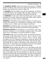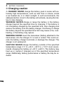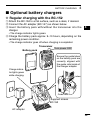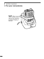
1
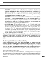
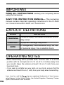
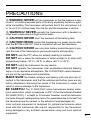
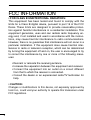
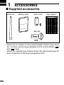
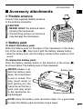
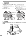
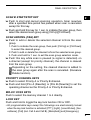
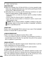
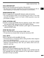
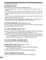
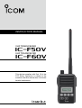
INSTRUCTION MANUAL
VHF TRANSCEIVER
iF50V
UHF TRANSCEIVER
iF60V
This device complies with Part 15 of the
FCC Rules. Operation is subject to the
condition that this device does not cause
harmful interference.
SAFETY TRAINING INFORMATION
W ARN ING
Your Icom radio generates RF electromagnetic energy
during transmit mode. This radio is designed for and
classified as “Occupational Use Only”, meaning it
must be used only during the course of employment
by individuals aware of the hazards, and the ways to
minimize such hazards. This radio is NOT intended
for use by the “General Population” in an uncontrolled
environment.
This radio has been tested and complies with the FCC RF exposure
limits for “Occupational Use Only”. In addition, your Icom radio complies
with the following Standards and Guidelines with regard to RF energy
and electromagnetic energy levels and evaluation of such levels for
exposure to humans:
• F CC OET Bulletin 65 Edition 97-01 Supplement C, Evaluating
Compliance with FCC Guidelines for Human Exposure to Radio
Frequency Electromagnetic Fields.
• American National Standards Institute (C95.1-1992), IEEE Standard
for Safety Levels with Respect to Human Exposure to Radio
Frequency Electromagnetic Fields, 3 kHz to 300 GHz.
• A merican National Standards Institute (C95.3-1992), IEEE
Recommended Practice for the Measurement of Potentially
Hazardous Electromagnetic Fields– RF and Microwave.
• The following accessories are authorized for use with this product.
Use of accessories other than those specified may result in RF
exposure levels exceeding the FCC requirements for wireless RF
exposure.; Belt Clip (MB-98), Rechargeable Li-Ion Battery Pack
(BP-227), Alkaline Battery Case (BP-226) and Speaker-microphone
(HM-168).
C AU TIO N
To ensure that your expose to RF electromagnetic
energy is within the FCC allowable limits for
occupational use, always adhere to the following
guidelines:
•D
O NOT operate the radio without a proper antenna attached, as
this may damaged the radio and may also cause you to exceed FCC
RF exposure limits. A proper antenna is the antenna supplied with
this radio by the manufacturer or antenna specifically authorized by
the manufacturer for use with this radio.
• DO NOT transmit for more than 50% of total radio use time (“50%
duty cycle”). Transmitting more than 50% of the time can cause FCC
RF exposure compliance requirements to be exceeded. The radio
is transmitting when the “TX indicator” lights red. You can cause the
radio to transmit by pressing the “PTT” switch.
• A LWAYS keep the antenna at least 2.5 cm (1 inch) away from
the body when transmitting and only use the Icom belt-clip which
is listed on page 38 when attaching the radio to your belt, etc.,
to ensure FCC RF exposure compliance requirements are not
exceeded. To provide the recipients of your transmission the best
sound quality, hold the antenna at least 5 cm (2 inches) from your
mouth, and slightly off to one side.
The information listed above provides the user with the information
needed to make him or her aware of RF exposure, and what to do to
assure that this radio operates with the FCC RF exposure limits of this
radio.
Electromagnetic Interference/Compatibility
During transmissions, your Icom radio generates RF energy that can
possibly cause interference with other devices or systems. To avoid
such interference, turn off the radio in areas where signs are posted
to do so. DO NOT operate the transmitter in areas that are sensitive to
electromagnetic radiation such as hospitals, aircraft, and blasting sites.
Occupational/Controlled Use
The radio transmitter is used in situations in which persons are exposed
as consequence of their employment provided those persons are fully
aware of the potential for exposure and can exercise control over their
exposure.
ii
IMPORTANT
READ ALL INSTRUCTIONS carefully and completely before
using the transceiver.
SAVE THIS INSTRUCTION MANUAL— This instruction
manual contains important operating instructions for the IC-F50V
vhf transceiver and IC-F60V uhf transceiver.
EXPLICIT DEFINITIONS
WORD
DEFINITION
RWARNING
Personal injury, fire hazard or electric shock
may occur.
CAUTION
NOTE
Equipment damage may occur.
If disregarded, inconvenience only. No risk
of personal injury, fire or electric shock.
OPERATING NOTES
• When transmitting with a portable radio, hold the radio in a vertical
position with its microphone 5 to 10 cm (2 to 4 inches) away from
your mouth. Keep the antenna at least 2.5 cm (1 inch) from your
head and body.
• If you wear a portable two-way radio on your body, ensure that the
antenna is at least 2.5 cm (1 inch) from your body when transmitting.
Icom, Icom Inc. and the
logo are registered trademarks of Icom Incorporated (Japan) in the United States, the United Kingdom, Germany, France,
Spain, Russia and/or other countries.
iii
PRECAUTIONS
R WARNING! NEVER hold the transceiver so that the antenna is very
close to, or touching exposed parts of the body, especially the face or eyes,
while transmitting. The transceiver will perform best if the microphone is 5
to 10 cm (2 to 4 inches) away from the lips and the transceiver is vertical.
R WARNING! NEVER operate the transceiver with a headset or
other audio accessories at high volume levels.
R CAUTION! NEVER short the terminals of the battery pack.
R CAUTION! NEVER connect the transceiver to a power source other
than the BP-226 or BP-227. Such a connection will ruin the transceiver.
R CAUTION! NEVER use non-Icom battery packs/chargers to prevent the loss of the transceiver’s good performance and warranty.
DO NOT push the PTT when not actually desiring to transmit.
DO NOT use or place the transceiver in direct sunlight or in areas with
temperatures below –30°C (–22°F) or above +60°C (+140°F).
DO NOT modify the transceiver for any reason.
DO NOT operate the transceiver near unshielded electrical blasting
caps or in an explosive atmosphere. The IC-F50V/F60V series transceivers are not the explosion-proof construction.
MAKE SURE the flexible antenna and battery pack are securely attached to the transceiver, and that the antenna and battery pack are dry
before attachment. Exposing the inside of the transceiver to water will
result in serious damage to the transceiver.
BE CAREFUL! The IC-F50V/F60V series transceivers employ waterproof construction, which corresponds to IPX7 of the international standard
IEC 60529 (2001), 1 m depth for 30 minutes. However, once the transceiver
has been dropped, waterproofing cannot be guaranteed due to the fact that
the transceiver may be cracked, or the waterproof seal damaged, etc.
Icom optional equipment is designed for optimal performance when
used with this transceiver. We are not responsible for the transceiver
being damaged or any accident caused when using non-Icom optional
equipment.
iv
FCC INFORMATION
• FOR CLASS B UNINTENTIONAL RADIATORS:
This equipment has been tested and found to comply with the
limits for a Class B digital device, pursuant to part 15 of the FCC
Rules. These limits are designed to provide reasonable protection against harmful interference in a residential installation. This
equipment generates, uses and can radiate radio frequency energy and, if not installed and used in accordance with the instructions, may cause harmful interference to radio communications.
However, there is no guarantee that interference will not occur in a
particular installation. If this equipment does cause harmful interference to radio or television reception, which can be determined
by turning the equipment off and on, the user is encouraged to try
to correct the interference by one or more of the following measures:
• Reorient or relocate the receiving antenna.
• Increase the separation between the equipment and receiver.
•C
onnect the equipment into an outlet on a circuit different
from that to which the receiver is connected.
• Consult the dealer or an experienced radio/TV technician for
help.
• CAUTION:
Changes or modifications to this device, not expressly approved by
Icom Inc., could void your authority to operate this transceiver under
FCC regulations.
TABLE OF CONTENTS
SAFETY TRAINING INFORMATION.............................................................i
IMPORTANT................................................................................................ iii
EXPLICIT DEFINITIONS............................................................................. iii
OPERATING NOTES.................................................................................. iii
PRECAUTIONS........................................................................................... iv
FCC INFORMATION....................................................................................v
TABLE OF CONTENTS............................................................................... vi
1 ACCESSORIES................................................................................. 1−3
■ Supplied accessories..........................................................................1
■ Accessory attachments.......................................................................2
2 PANEL DESCRIPTION.................................................................... 4−12
■ Front, top and side panels...................................................................4
■ Function display..................................................................................6
■ Programmable function keys...............................................................7
3 BASIC OPERATION...................................................................... 13−22
■ Turning power ON..............................................................................13
■ Channel selection..............................................................................13
■ Call procedure...................................................................................14
■ Receiving and transmitting................................................................15
■ User set mode..................................................................................19
■ Emergency transmission...................................................................20
■ Scrambler function............................................................................20
■ Stun function.....................................................................................20
■ Recording function (Depends on the version)...................................21
4 BATTERY CHARGING.................................................................. 23−30
■ Caution..............................................................................................23
■ Optional battery chargers..................................................................26
5 BATTERY CASE............................................................................ 31−32
■ Optional battery case (BP-226).........................................................31
6 SPEAKER-MICROPHONE............................................................ 33−34
■ Optional HM-168 description.............................................................33
■ Attachment........................................................................................34
7 SWIVEL BELT CLIP...................................................................... 35−36
■ Optional MB-86 contents...................................................................35
■ Attaching...........................................................................................35
■ Detaching..........................................................................................36
8 OPTIONS....................................................................................... 37−40
vi
1
ACCESSORIES
■ Supplied accessories
Antenna
Battery pack
Jack cover
Key sticker*
Belt clip
*There are no names on the programmable function keys since
the functions can be freely assigned to [P0] to [P3], [Red], [
]
and [
] keys.
Attach the supplied key stickers above the appropriate keys for
easy recognition of that key’s assigned function.
ACCESSORIES
1
■ Accessory attachments
1
D Flexible antenna
2
Connect the supplied flexible antenna
to the antenna connector.
3
4
AUTION!
C
•N
EVER HOLD the antenna when
carrying the transceiver.
•T
ransmitting without an antenna
may damage the transceiver.
5
6
7
8
D Battery pack
To attach the battery pack:
Slide the battery pack on the back of the transceiver in the direction of the arrow (q), then lock it with the battery release button.
• Slide the battery pack until the battery release button makes a ‘click’
sound.
To release the battery pack:
Push the battery release button in the direction of the arrow (w)
as shown below. The battery pack is then released.
EVER release or atN
tach the battery pack
when the transceiver
is wet or soiled. This
may result water or
dust getting into the
transceiver/batter y
pack and may result
in the transceiver being damaged.
Battery pack
9
10
11
12
13
14
15
q
16
w
17
18
Battery release button
19
20
OTE: Keep the battery pack terminals clean. It’s a good idea
N
to clean the battery pack terminals once a week.
1
ACCESSORIES
D Jack cover
ttach the jack cover when the optional equipment is not used.
A
To attach the jack cover:
To detach the jack cover:
q Insert the jack cover into the e Unscrew the screw using a
[SP MIC] jack.
phillips screwdriver.
w Tighten the screw.
r D etach the jack cover for
the optional equipment
connection.
[SP MIC] jack
Jack cover
r
q
e
Screw
w
D Belt clip
Attach the belt clip to the back of the transceiver with the supplied
screws.
Supplied screws
PANEL DESCRIPTION
■ Front, top and side panels
2
1
2
w
3
e
q
4
5
i
u
r
6
Speaker
7
Microphone
8
Function display
(p. 6)
9
t
10
11
12
13
y
qVOLUME CONTROL [VOL]
Turns power ON and adjusts the audio level.
wRED BUTTON
The desired function can be assigned by your dealer. (p. 7)
eANTENNA CONNECTOR
Connects the supplied antenna. (p. 2)
14
15
16
17
18
19
20
2
PANEL DESCRIPTION
rEXTERNAL SPEAKER-MICROPHONE JACK [SP MIC]
Connects the optional speaker-microphone, etc.
[SP MIC] jack cover
NOTE: KEEP the [SP MIC]
jack cover attached to the
transceiver when the optional
equipment is not used.
(See p. 3 for details)
tDEALER-PROGRAMMABLE KEYS [P0] to [P3]
The desired functions can be assigned independently by your
dealer. (p. 7)
yCH UP AND DOWN KEYS [
]/[
]
Push to select an operating channel, etc.
*Desired functions can be assigned independently by your dealer.
(p. 7)
uTRANSMIT/BUSY INDICATOR
Lights red while transmitting; lights green while receiving a
signal, or when the squelch is open.
iPTT SWITCH [PTT]
➥ Push and hold to transmit; release to receive.
➥ When the recording function is activated, TX voice message
can be recorded while pushing and holding [PTT]. (p. 21)
PANEL DESCRIPTION
2
■ Function display
q w
2
e r t y u i
o
qRECORD INDICATOR
➥ Appears when an unread message is in the memory.
➥ Blinks while recording.
wLOW POWER INDICATOR
Appears when low output power is selected.
eAUDIBLE INDICATOR
➥ Appears when the channel is in the ‘audible’ (unmute) condition.
➥ Appears when the specified 2/5-tone/BIIS*1/MDC*2 code is
received.
rCOMPANDER INDICATOR
Appears when the compander function is activated.
tKEY LOCK INDICATOR
Appears when the key lock function is activated.
ySCRAMBLER INDICATOR
Appears when the voice scrambler function is activated.
uBELL INDICATOR
Appears/blinks when the specific 2/5-tone/BIIS*1/MDC*2 code is
received, according to the pre-programming.
iBATTERY INDICATOR
Appears or blinks when the battery power decreases to a
specified level.
oALPHANUMERIC DISPLAY
Displays an operating channel number, channel names, Set
mode contents, DTMF code, etc.
*1 BIIS operation only *2 MDC operation only
2
PANEL DESCRIPTION
■ Programmable function keys
The following functions can be assigned to [P0], [P1], [P2], [P3],
[Red], [
] and [
] programmable function keys.
Consult your Icom dealer or system operator for details concerning your transceivers programming.
If the programmable function names are bracketed in the following
explanations, the specific key is used to activate the function depends on programming.
CH UP AND DOWN KEYS
➥Push to select an operating channel.
➥Push to select a transmit code channel after pushing [TX Code
CH Select].
➥Push to select a DTMF channel after pushing [DTMF Autodial].
➥Push to select a scan group after pushing and holding [Scan A
Start/Stop]/[Scan B Start/Stop].
ZONE SELECT KEY
Push this key, then select the desired zone using [CH Up]/[CH
Down].
What is a “zone”?—The desired channels are assigned into a
zone according to the intended use for grouping. For example,
‘Staff A’ and ‘Staff B’ are assigned into a “Business” zone, and
‘John’ and ‘Cindy’ are assigned into a “Private” zone.
SCAN A START/STOP KEY
➥This key’s operation depends on the Power ON Scan setting.
When the power ON scan function is turned OFF;
Push to start and cancel scanning operation.
When the power ON scan function is turned ON;
Push to pause scanning, then resumes scanning after a specified time period has passed.
➥Push and hold this key for 1 sec. to indicate the scan group, then
select the desired scan group using [CH Up]/[CH Down].
PANEL DESCRIPTION
2
SCAN B START/STOP KEY
➥Push to start and cancel scanning operation. Scan resumes
after a specified time period has passed when scan is cancelled
except for this key.
➥Push and hold this key for 1 sec. to indicate the scan group, then
select the desired scan group using [CH Up]/[CH Down].
2
SCAN ADD/DEL (TAG) KEY
➥Push to add or delete the selected channel to/from the scan
group.
1. Push to indicate the scan group, then push [CH Up] or [CH Down]
to select the desired group.
2. Push to add or delete the channel to/from the selected scan group.
3. Push and hold for 1 sec. to exit the scan group selection mode.
➥Push this key while scan is paused (a signal is detected) on
a channel (except for priority channel,) the channel is cleared
from the scan group.
Depending on the setting, the cleared channel is added to
the scan group again after the scan is cancelled. (Nuisance
Delete function)
PRIORITY CHANNEL KEYS
➥Push to select Priority A or Priority B channel.
➥Push and hold [Prio A (Rewrite)] or [Prio B (Rewrite)] to set the
operating channel as the Priority A or Priority B channel.
MR-CH 1/2/3/4 KEYS
Push to select the memory channel 1 to 4 directly.
LOCK KEY
Push and hold to toggle the key lock function ON or OFF.
•A
ll programmable keys except the followings are electronically locked
when the key lock function is activated: [PTT], [Light], [Lone Worker], [Surveillance], [Call] (incl. Call A and Call B), [Moni(Audi)] and [Emergency].
2
PANEL DESCRIPTION
MONITOR KEY
➥Mute and release the CTCSS (DTCS) or 2-tone squelch mute.
Open any squelch/deactivate any mute while pushing and holding this key. (LMR operation only)
➥A ctivates one of (or two of) the following functions on each
channel independently: (PMR operation only)
• Push and hold to un-mute the channel (audio is emitted; ‘Audible’
condition).
• Push to mute the channel (sets to ‘Inaudible’ only).
• Push after the communication is finished to send a ‘reset code’.
(BIIS operation only)
N
OTE: The un-mute condition (‘Audible’ condition) may automatically return to the mute condition (‘Inaudible‘ condition)
after a specified period.
LIGHT KEY
Push to turn the backlight ON for about 5 sec. even if the backlight
function is turned OFF in user set mode.
LONE WORKER KEY
Push to turn the Lone Worker function ON or OFF.
• If the Lone Worker function is activated, the Emergency function is
automatically turned ON after the specified time period has passed
with no operation is performed.
HIGH/LOW KEY
Push to select the transmit output power temporarily or permanently, depending on the pre-setting.
• Ask your dealer for the output power level for each selection.
C.TONE CHANNEL ENTER KEY
Push to enter the continuous tone channel selection mode, and
push [CH Up]/[CH Down] to change the tone frequency/code setting. The selected channel remains set as the continuous tone
channel until another channel is designated as such.
PANEL DESCRIPTION
2
TALK AROUND KEY
Push to turn the talk around function ON and OFF.
• The talk around function equalizes the transmit frequency to the receive frequency for transceiver-to-transceiver communication.
2
WIDE/NARROW KEY
Push to toggle the IF bandwidth between wide and narrow.
• The wide passband width can be selected from 25.0 or 20.0 kHz
using the CS-F50V cloning software. (PMR operation only) Ask
your dealer for details.
DTMF AUTODIAL KEY
➥Push to enter the DTMF channel selection mode. Then select
the desired DTMF channel using [CH Up]/[CH Down].
➥After selecting the DTMF channel, push again to transmit the
selected DTMF code.
DTMF RE-DIAL KEY
Push to transmit the last-transmitted DTMF code.
• TX memories are cleared after turning the transceiver OFF.
CALL KEYS
Push to transmit a 2/5-tone/BIIS ID code.
• Call transmission is necessary before calling another station depending on your signalling system.
• [Call A] and/or [Call B] may be available when your system employs
selective ‘Individual/Group’ calls. Ask your dealer which call is assigned to each key.
SURVEILLANCE KEY
Push to turn the surveillance function ON or OFF.
When this function is turned ON, the beep is not emitted and the
LCD backlight and the LED indicator do not light when a signal is
received or a key is pushed.
10
2
PANEL DESCRIPTION
EMERGENCY KEYS
Push and hold to transmit the emergency call.
• T he emergency call transmits with beeps; the display does not
change.
• The transceiver can transmit the emergency call silently or with the
display changes depending on the pre-setting. Ask your dealer for
details.
• I f you want to cancel the emergency call, push and hold the key
again before transmitting the call.
• The emergency call is transmitted one time only or repeatedly until
receiving a control code, depending on the pre-setting.
TX CODE ENTER KEY (PMR operation only)
Push to enter the TX code edit mode. Then set the desired digit
using [CH Up]/[CH Down]. (p. 18)
TX CODE CHANNEL SELECT KEY
➥Push to enter the TX code channel selection mode. Then select
the desired channel using [CH Up]/[CH Down]. (p. 17)
➥While in the TX code channel selection mode, push and hold for
1 sec. to enter the TX code edit mode. Then set the desired digit
using [CH Up]/[CH Down]. (p. 17; PMR operation only)
TX CODE CHANNEL UP/DOWN KEYS
Push to select a TX code channel directly.
ID-MR SELECT KEY (PMR operation only)
➥Recalls detected ID codes.
• Push this key, then push [CH Up]/[CH Down] for selection.
• Up to 5 ID’s are memorized.
➥Push and hold to erase the selected memorized ID’s.
VOICE SCRAMBLER FUNCTION
Push to turn the voice scrambler function ON and OFF.
11
PANEL DESCRIPTION
2
COMPANDER KEY
Push to turn the compander function ON and OFF.
The compander function reduces noise components from the
transmitting audio to provide clearer communication.
1
USER SET MODE KEY
➥Push and hold to enter user set mode.
4
• While in user set mode, push this key to select an item, and push
[CH Up]/[CH Down] to change the value or condition.
➥Push and hold this key again to exit user set mode.
2
3
5
6
• U ser set mode is also available via the ‘Power ON function’.
Please refer to p. 19 also.
7
PLAYBACK KEY (p. 22)
➥Push to playback the recorded messages in sequence, starting
with the latest one.
9
• A short beep is emitted after playing back each message.
• A long beep is emitted after playing back all messages.
• A n error beep is emitted when there are no messages in the
memory.
8
10
11
12
➥While playing back the message, push and hold for 1 sec. to
delete the selected message.
13
PLAYBACK/REC KEY (pgs. 21, 22)
➥Push to playback the recorded messages in sequence, starting
with the latest one.
15
• A short beep is emitted after playing back each message.
• A long beep is emitted after playing back all messages.
• “NO REC” is displayed when no message is in the memory.
➥Push and hold for 1 sec. to start recording. Push again to stop
recording.
➥While playing back the message, push and hold for 1 sec. to
delete the selected message.
14
16
17
18
19
20
12
3
BASIC OPERATION
■ Turning power ON
qRotate [VOL] to turn power ON.
• When the opening vibration function is turned ON, the transceiver
vibrates for 2 sec. Ask your dealer for details.
wIf the transceiver is programmed for a start up passcode, input
digit codes as directed by your dealer.
• The keys in the table below can be used for password input:
•T
he transceiver detects numbers in the same block as identical.
Therefore “01234” and “56789” are the same.
or
KEY
NUMBER
0
5
1
6
2
7
3
8
4
9
eWhen the “PASSWORD” indication does not clear after inputting 4 digits, the input code number may be incorrect. Turn the
power off and start over in this case.
■ Channel selection
Several types of channel selections are available. Methods may
differ according to your system set up.
NON-ZONE TYPE:
Push [CH Up]/[CH Down] to select the desired operating channel
in sequence; or, push one of [MR-CH 1] to [MR-CH 4] to select a
channel directly.
ZONE TYPE:
Push [Zone] then push [CH Up]/[CH Down] to select the desired zone.
AUTOMATIC SCAN TYPE:
Channel setting is not necessary for this type. When turning the
power ON, the transceiver automatically starts scanning. Scanning
stops when receiving a call.
13
BASIC OPERATION
3
■ Call procedure
1
When your system employs tone signalling (excluding CTCSS and
DTCS), this call procedure may be necessary prior to voice transmission. The tone signalling employed may be a selective calling
system which allows you to call specific station(s) only and prevent
unwanted stations from contacting you.
2
3
4
5
qSelect the desired TX code channel or 2/5-tone code according
to your System Operator’s instructions.
6
• This may not be necessary depending on programming.
• Refer to pgs. 17, 18 for selection.
7
wPush [Call] (assigned to one of the dealer programmable keys).
eAfter transmitting, the remainder of your communication can be
carried out in the normal fashion.
Selective calling
Non-selective calling
8
9
10
11
12
13
14
15
16
17
18
19
20
14
3
BASIC OPERATION
■ Receiving and transmitting
OTE: Transmitting without an antenna may damage the transN
ceiver. See p. 2 for antenna attachment.
Receiving:
qRotate [VOL] to turn power ON.
wPush [CH Up] or [CH Down] to select a channel.
eWhen receiving a call, adjust the audio output level to a comfortable listening level.
Transmitting:
Wait for the channel to become clear to avoid interference.
qWhile pushing and holding [PTT], speak into the microphone at
a normal voice level.
• When a tone signalling system is used, the call procedure described at the previous page may be necessary.
wRelease [PTT] to return to receive.
IMPORTANT: To maximize the readability of your signal;
1. Pause briefly after pushing [PTT].
2. Hold the microphone 5 to 10 cm (2 to 4 inches) from your
mouth, then speak into the microphone at a normal voice
level.
15
BASIC OPERATION
3
D Receiving note
• Vibration function (Depends on the version)
When the matched RX code signal is received, the transceiver
may vibrate for a specified time period, depending on the presetting. Push any key or [PTT] to stop the vibration.
3
NOTE:
• The transceiver cannot stop the vibration suddenly after pushing any key or [PTT].
• T he vibration sound may be heard at the communication
party, or be recorded if the recording function is activated
when [PTT] is pushed to stop the vibration.
D Transmitting notes
• Transmit inhibit function
The transceiver has several inhibit functions which restrict transmission under the following conditions:
- The channel is in mute condition (‘Inaudible’ condition; “ ”
does not appear).
- The channel is busy.
- Un-matched (or matched) CTCSS is received. (Depending on
the pre-setting)
- The selected channel is a ‘receive only’ channel.
• Time-out timer
After continuous transmission for the pre-programmed time period,
the time-out timer starts, causing the transceiver to stop transmitting.
• Penalty timer
Once the time-out timer starts, transmission is further inhibited for
a period determined by the penalty timer.
16
3
BASIC OPERATION
D TX code channel selection
If the transceiver has [TX Code CH Select] assigned to it, the indication can be toggled between the operating channel number
(or name) and TX code channel number (or name). When the
TX code channel number (or name) is displayed, [CH Up] or [CH
Down] selects the TX code channel.
USING [TX CODE CH SELECT] KEY:
qPush [TX Code CH Select]— a TX code channel number (or
name) appears.
wPush [CH Up] or [CH Down] to select the desired TX code
channel.
eAfter selecting, push [TX Code CH Select] to set.
• Return to the stand-by mode.
rPush [Call] to transmit the selected TX code.
USING [TX CODE CH UP]/[TX CODE CH DOWN] KEY:
If the transceiver has a [TX Code CH Up] or [TX Code CH Down]
key assignment, the programmed TX code channel can be selected directly when pushed.
D TX code number edit (PMR operation only)
If the transceiver has [TX Code CH Select] or [TX Code Enter] assigned to it, TX code contents can be edited within the allowable
digits.
USING [TX CODE CH SELECT] KEY:
qPush [TX Code CH Select] to enter the TX code channel selection mode.
• Select the desired operating channel before entering the TX code
channel selection mode if necessary.
wPush [TX Code CH Select] for 1 sec. to enter the TX code edit
mode.
• The digit to be edited blinks.
17
BASIC OPERATION
3
ePush [TX Code CH Select] to select the desired digit to be edited.
rPush [CH Up]/[CH Down] to select the desired digit.
tPush [TX Code CH Select] to set. The digit to the right will blink
automatically.
yRepeat r and t to edit all allowable digits.
uAfter editing, push [TX Code CH Select] to set.
3
• Return to the stand-by mode.
iPush [Call] to transmit.
USING [TX CODE ENTER] KEY:
qA fter pushing [TX Code CH Select], push [CH Up] or [CH
Down], or push [TX Code CH Up] or [TX Code CH Down] to select the desired TX code channel.
wPush [TX Code Enter] to enter the TX code edit mode.
• The digit to be edited blinks.
ePush [TX Code Enter] to select the desired digit to be edited.
rPush [CH Up]/[CH Down] to select the desired digit.
tPush [TX Code Enter] to set. The digit to the right will blink automatically.
yRepeat r and t to edit all allowable digits.
uAfter editing, push [TX Code Enter] to set.
• Return to the stand-by mode.
iPush [Call] to transmit.
D DTMF transmission
If the transceiver has [DTMF Autodial] assigned to it, the automatic
DTMF transmission function is available. Up to 8 DTMF channels
are available.
qPush [DTMF Autodial]— a DTMF channel appears.
wPush [CH Up] or [CH Down] to select the desired DTMF channel.
ePush [DTMF Autodial] to transmit the DTMF code to the selected DTMF channel.
18
3
BASIC OPERATION
■ User set mode
User set mode is accessed at power ON and allows you to set
seldom-changed settings. You can “customize” the transceiver operation to suit your preferences and operating style.
Entering the user set mode:
qW hile pushing and holding [
power ON.
] and [
], rotate [VOL] to
• Turn power OFF in advance.
• “ SET MODE” appears for 1 sec.
wPush and hold [P0] for 1 sec. to enter user set mode.
ePush [P0] momentarily to select the appropriate item.
] or [
] to set the desired level/condition.
Then push [
• Available set mode functions are Backlight, Beep, SQL Level,
Ringer Level, AF Min level, Mic Gain, VOX Gain*, VOX Delay*,
Battery Voltage, Signal Moni, Vibration and Lone Worker.
rPush and hold [P0] again to exit set mode.
* Appears when the optional headset is connected.
User set mode is also available using a programmable key. Please
refer to p. 12 [User Set Mode] section for instructions regarding
using the key assigned for user set mode.
OTE: [
N
], [
] and [P0] activate while in the user set
mode regardless of the assigned key functions.
19
BASIC OPERATION
3
■ Emergency transmission
When [Emergency] is pushed for the specified time period, an
emergency signal is automatically transmitted.
When [Emergency] is pushed for the specified time period, the
DTMF or 5-tone* emergency signal is transmitted once or repeatedly on the emergency channel. However, when no emergency
channel is specified, the signal is transmitted on the previously
selected channel.
3
If you want to cancel the emergency call, push and hold the key
again before transmitting the call.
*Depending on the operating model type.
■ Scrambler function
The scrambler function provides private communication between
stations.
qPush [Scrambler] to turn the scrambler function ON.
• “ ” appears.
wPush [Scrambler] again to turn the scrambler function OFF.
• “ ” disappears.
■ Stun function
When the specified ID, set as a kill key, is received, the stun function is activated.
When the kill ID is received, the transceiver switches to the password required condition. Entering of the password via the keypad
is necessary to operate the transceiver again in this case.
20
3
BASIC OPERATION
■ Recording function (Depends on the version)
The transceiver has a recording function that records the TX/RX
voice messages. When the specified ID is received, the automatic
recording function activates and records the voice message for a
specified time period.
Or, if the transceiver has [Playback/Rec] assigned to it, manual
recording is also available.
The maximum record length is 480 sec., and the number of recordable messages depend on the record length. Ask your dealer
for details.
e.g. When the record length is 10 sec., 48 messages are recordable.
Automatic recording:
qWhen the specified ID is received, the recording function is automatically activated.
•“
” blinks.
wWhile pushing and holding [PTT], speak into the microphone at
a normal voice level.
• The TX voice message is recorded.
eRelease [PTT] to receive.
• The RX voice message is recorded.
rThe recording operation automatically stops after the following:
the specified time has expired, the recording memory is full,
pushing any key but [PTT], or transmitting a single tone.
• “ ” stops blinking.
• Pushing [Playback/Rec] (if assigned) also stops recording.
Manual recording:
qPush and hold [Playback/Rec] for 1 sec. to activate the recording function.
•“
” blinks.
wWhile pushing and holding [PTT], speak into the microphone at
a normal voice level.
21
• The TX voice message is recorded.
BASIC OPERATION
3
1
eRelease [PTT] to receive.
• The RX voice message is recorded.
rPush [Playback/Rec] again to stop recording.
• “ ” stops blinking.
•T
he recording operation automatically stops after the following: the
recording memory is full, pushing any key but [PTT], or transmitting a single tone.
Playing back:
The recorded voice messages are played back with [Playback] or
[Playback/Rec].
• “ ” appears on the function display when the unplayed message is
in the recording memory.
➥Push [Playback] or [Playback/Rec] to playback the recorded
message in sequence starting with the latest one.
• Push [CH Up] or [CH Down] to select the desired message.
• A short beep is emitted after playing back each message.
• A long beep is emitted after playing back all messages.
• During playback mode, “ ” appears when the unplayed message
is played back, or “ ” disappears when the played message is
played back.
• “ ” disappears after playing back the unplayed message for the
specified time period.
• If you push [PTT] while playing back the message, the transceiver
stops playing back, and then starts to transmit.
Deleting the message:
➥While playing back the message, push and hold [Playback] or
[Playback/Rec] for 1 sec. to delete the playing back message.
➥While pushing and holding [P0] and [CH Up], turn power ON to
delete all messages in the recording memory.
2
3
4
5
6
7
8
9
10
11
12
13
14
15
16
17
18
19
20
22
4
BATTERY CHARGING
■ Caution
Misuse of Lithium-Ion batteries may result in the following
hazards: smoke, fire, or the battery may rupture. Misuse can
also cause damage to the battery or degradation of battery
performance.
R DANGER! Use and charge only specified Icom battery packs
with Icom radios or Icom charger. Only Icom battery packs are
tested and approved for use and charge with Icom radios or Icom
charger. Using third-party or counterfeit battery packs or charger
may cause smoke, fire, or cause the battery to burst.
D Battery caution
R DANGER! DO NOT hammer or otherwise impact the battery.
Do not use the battery if it has been severely impacted or dropped,
or if the battery has been subjected to heavy pressure. Battery
damage may not be visible on the outside of the case. Even if the
surface of the battery does not show cracks or any other damage,
the cells inside the battery may rupture or catch fire.
R DANGER! NEVER use or leave battery packs in areas with
temperatures above +60˚C (+140˚F). High temperature buildup in
the battery, such as could occur near fires or stoves, inside a sun
heated car, or in direct sunlight may cause the battery to rupture
or catch fire. Excessive temperatures may also degrade battery
performance or shorten battery life.
R DANGER! DO NOT expose the battery to rain, snow, seawater,
or any other liquids. Never charge or use a wet battery. If the battery gets wet, be sure to wipe it dry before using. The battery is
not waterproof.
R DANGER! NEVER incinerate used battery packs since internal
battery gas may cause them to rupture, or may cause an explosion.
23
BATTERY CHARGING
4
R DANGER! NEVER solder the battery terminals or NEVER
modify the battery pack. This may cause heat generation, and the
battery may rupture, emit smoke or catch fire.
1
R DANGER! Use the battery only with the transceiver for which it
is specified. Never use a battery with any other equipment, or for
any purpose that is not specified in this instruction manual.
3
R DANGER! If fluid from inside the battery gets in your eyes,
blindness can result. Rinse your eyes with clean water, without
rubbing them, and see a doctor immediately.
5
WARNING! Immediately stop using the battery if it emits an abnormal odor, heats up, or is discolored or deformed. If any of these
conditions occur, contact your Icom dealer or distributor.
7
WARNING! Immediately wash, using clean water, any part of the
body that comes into contact with fluid from inside the battery.
9
WARNING! NEVER put the battery in a microwave oven, highpressure container, or in an induction heating cooker. This could
cause a fire, overheating, or cause the battery to rupture.
11
CAUTION! Always use the battery within the specified temperature range for the transceiver (–30˚C to +60˚C; –22˚F to +140˚
F) and the battery itself (–10˚C to +60˚C; 14˚F to +140˚F). Using
the battery out of its specified temperature range will reduce the
battery’s performance and battery life. Please note that the specified temperature range of the battery may exceed that of the
transceiver. In such cases, the transceiver may not work properly
because it is out of its operating temperature range.
CAUTION! Shorter battery life could occur if the battery is left fully
charged, completely discharged, or in an excessive temperature
environment (above +45˚C; +113˚F) for an extended period of
time. If the battery must be left unused for a long time, it must be
detached from the radio after discharging. You may use the battery
until the remaining capacity is about half, then keep it safely in a
cool dry place with the temperature between –20˚C to +35˚C (–4˚
F to +95˚F).
2
4
6
8
10
12
13
14
15
16
17
18
19
20
24
4
BATTERY CHARGING
D Charging caution
R DANGER! NEVER charge the battery pack in areas with extremely high temperatures, such as near fires or stoves, inside
a sun heated car, or in direct sunlight. In such environments, the
safety/protection circuit in the battery will activate, causing the battery to stop charging.
WARNING! NEVER charge or leave the battery in the battery
charger beyond the specified time for charging. If the battery is
not completely charged by the specified time, stop charging and
remove the battery from the battery charger. Continuing to charge
the battery beyond the specified time limit may cause a fire, overheating, or the battery may rupture.
WARNING! NEVER insert the transceiver (battery attached to the
transceiver) into the charger if it is wet or soiled. This could corrode the battery charger terminals or damage the charger. The
charger is not waterproof.
CAUTION! NEVER charge the battery outside of the specified
temperature range: 0˚C to +45˚C; +32˚F to +113˚F. Icom recommends charging the battery at +20˚C (+68˚F). The battery may
heat up or rupture if charged out of the specified temperature
range. Additionally, battery performance or battery life may be reduced.
25
BATTERY CHARGING
4
■ Optional battery chargers
1
D Regular charging with the BC-152
2
qAttach the BC-152 to a flat surface, such as a desk, if desired.
wConnect the AC adapter (BC-147) as shown below.
eI nsert the battery pack with/without the transceiver into the
charger.
3
4
• The charge indicator lights green.
5
rCharge the battery pack approx. 9–10 hours, depending on the
remaining power condition.
6
• The charge indicator goes off when charging is completed.
Transceiver
Battery pack
7
8
Turn power OFF
9
Ensure the guide lobes
on the battery pack are
correctly aligned with
the guide rails inside of
the charger adapter.
Charge indicator lights green
while charging.
10
11
12
13
Lobes
14
15
16
17
Guide rails
18
Supplied screws
BC-152
19
20
AC adapter
26
4
BATTERY CHARGING
D For your convenience
Eyelet
USE a rubber band to
secure the transceiver while charging, if
desired.
27
BATTERY CHARGING
4
D AD-100 installation
The AD-100 charger adapter must be installed into the BC-119N
or BC-121N before battery charging.
➥Connect the AD-100 charger adapter and the BC-119N/BC121N as below, then install the AD-100 into the holder space of
the BC-119N or BC-121N with the supplied screws.
Connectors
AD-100
1
2
3
4
5
6
7
8
9
Plugs
10
11
12
Screws supplied with
the charger adapter
13
14
15
16
17
18
19
20
* This illustration is described
with the BC-119N.
28
4
BATTERY CHARGING
D Rapid charging with the BC-119N+AD-100
The optional BC-119N provides rapid charging of the optional LiIon battery pack. The following items are additionally required:
• An AD-100 charger adapter
• An AC adapter (may be supplied with BC-119N depending on
version) or the DC power cable (OPC-515L/CP-17L).
Battery pack
Transceiver
Turn power OFF
AC adapter
(Not supplied with
some versions.)
AD-100 charger
adapter is installed in BC-119N.
Optional OPC-515L
(for 13.8 V power
source) or CP-17L
(for 12 V cigarette
lighter socket) can
be used instead of
the AC adapter.
*See the instruction manual for
details of the
charger LED indication, operation, etc.
IMPORTANT!:
Ensure the guide lobes
on the battery pack are
correctly aligned with
the guide rails inside of
the charger adapter.
Lobes
Guide rails
29
BATTERY CHARGING
4
D Rapid charging with the BC-121N+AD-100
The optional BC-121N allows up to 6 battery packs to be charged
simultaneously. The following items are additionally required.
• Six AD-100 charger adapter
• An AC adapter (BC-157) or the DC power cable (OPC-656)
Transceiver
Battery pack
Turn power OFF
1
2
3
4
5
6
*See the instruction
manual for details of
the charger LED indication, operation, etc.
7
AD-100 charger
adapters are installed in each
slot.
AC adapter
(Purchase
separately.)
8
9
10
11
12
13
ER
HARG
TI-C
MUL
14
15
DC power cable
(OPC-656)
(Connect with the
DC power supply;
13.8 V/at least 7 A)
IMPORTANT!:
Ensure the guide
lobes on the battery pack are correctly aligned with
the guide rails inside of the charger adapter.
Lobes
16
17
18
Guide rails
19
20
30
5
BATTERY CASE
■ Optional battery case (BP-226)
When using the optional battery case attached to the transceiver,
install 5 × AA (LR6) size alkaline batteries as illustrated at right.
The BP-226 is constructed to the IPX4 waterproof standard (IEC
60529, 2006).
qHook your finger under the latch, and open the cover in the direction of the arrow (q). (Fig.1)
wInstall 5 × AA (LR6) size alkaline batteries. (Fig.2)
• Install the alkaline batteries only.
• Be sure to observe the correct polarity.
• Do not pin the ribbon under the batteries.
eClose the cover by fitting in the direction of the arrow (w) first,
then check that the latch is in place (e). (Fig.1)
• Be sure the gasket and the ribbon are seated correctly, and do not
protrude from the battery case. (Fig.3)
CAUTION:
• When installing batteries, make sure they are all the same
brand, type and capacity. Also, do not mix new and old batteries together.
•K
eep battery contacts clean. It’s a good idea to clean battery
terminals once a week.
• Never incinerate used battery cells since internal battery gas
may cause them to rupture.
• Never expose a detached battery case to water. If the battery
case gets wet, be sure to wipe it dry before using it.
31
BATTERY CASE
5
1
2
Latch
BP-226
Fig.1
3
q
4
5
w
6
e
7
8
9
Fig.2
Ribbon
10
11
12
13
14
15
16
Fig.3
17
Gasket
18
19
Ribbon
20
32
6
SPEAKER-MICROPHONE
■ Optional HM-168 description
Alligator type clip
To attach the speaker-mic.
to your shirt or collar, etc.
PTT switch
Transmits while pushed
Receives while released
Microphone
Speaker
Turn the transceiver power OFF
when connecting the HM-168.
NEVER immerse the connector in water. If the connector becomes
wet, be sure to dry it BEFORE attaching it to the transceiver.
33
NOTE: The microphone is located at the top of the speaker-microphone, as shown in the diagram above. To maximize the
readability of your transmitted signal (voice), hold the microphone approx. 5 to 10 cm (2 to 4 inches) from your mouth, and
speak in a normal voice level.
SPEAKER-MICROPHONE
6
■ Attachment
1
Attach the connector of the speaker-microphone into the [SP MIC]
jack on the transceiver and tighten the screw.
2
3
4
5
6
CAUTION: Attach the [SP
MIC] jack snugly, but do
not overtighten.
A loose connection will
allow water intrusion into
the jack; an overtightened
jack will damage the connector pins in the transceiver.
IMPORTANT: KEEP the [SP MIC] jack cover attached to the
transceiver when the speaker-microphone is not in use. (p. 3)
Water will not get into the transceiver even if the cover is not attached, however, the terminals (pins) will become rusty, or the
transceiver will function abnormally if the connector becomes
wet.
7
8
9
10
11
12
13
14
15
16
17
18
19
20
34
7
SWIVEL BELT CLIP
■ Optional MB-86 contents
Qty.
q Belt clip .......................................................................................... 1
w Base clip ........................................................................................ 1
e Screws ........................................................................................... 2
■ Attaching
qAttach the base clip to the back of the transceiver.
Supplied screws
Base clip
wClip the belt clip to a part of your belt and insert the base clip
into the belt clip.
Belt clip
35
SWIVEL BELT CLIP
7
eOnce the transceiver is locked in place, it will swivel 360 degrees.
1
2
3
4
5
6
7
8
■ Detaching
Turn the transceiver upside down, and pull out from the belt clip.
Then detach the base clip from the back of the transceiver.
9
10
11
12
13
14
15
16
17
C
AUTION!
OLD THE TRANSCEIVER TIGHTLY WHEN ATTACHING OR
H
DETACHING THE TRANSCEIVER FROM THE BELT CLIP.
Otherwise the transceiver may not be attached to the holder,
or may not swivel properly if the transceiver is accidentally
dropped and the base clip is scratched or damaged.
18
19
20
36
OPTIONS
8
D BATTERY PACK/CASE
•BP-226 battery case
Battery case for 5 × AA (LR6) alkaline cells.
•BP-227 li-ion battery pack
7.2 V/1700 mAh Li-Ion battery pack. BP-227 must be charged
with the optional BC-152/BC-119N/BC-121N.
D CHARGERS
•BC-152 desktop charger + BC-147 ac adapter
Used for regular charging of the battery pack. The AC adapter,
BC-147, must be purchased separately.
Charging time: approx. 9–10 hours for BP-227.
•BC-119N desktop charger + AD-100 charger adapter
+ BC-145 ac adapter
For rapid charging of battery packs. An AC adapter is not supplied with some versions.
Charging time: approx. 2 to 2.5 hours for BP-227.
•BC-121N multi-charger + AD-100 charger adapter (6 pcs.)
+ BC-157 ac adapter
For rapid charging of up to 6 battery packs (six AD-100’s are
required) simultaneously. An AC adapter should be purchased
separately.
Charging time: approx. 2 to 2.5 hours for BP-227.
D DC CABLES
•CP-17L cigarette lighter cable
Allows charging of the battery pack through a 12 V cigarette
lighter socket. (For BC-152/BC-119N)
•OPC-515L/OPC-656 dc power cables
Allows charging of the battery pack using a 13.8 V power source
instead of the AC adapter.
OPC-515L: For BC-152/BC-119N
OPC-656 : For BC-121N
37
OPTIONS
8
D BELT CLIPS
•MB-86 swivel belt clip
•MB-98 belt clip
Exclusive alligator-type belt clip.
•MB-96N/MB-96F leather belt hangers
D OTHER OPTIONS
•HM-138/HM-168 speaker-microphones
Full-sized waterproof (IPX7 waterproof protection) speaker-microphones including alligator type clip to attach to your shirt or collar, etc.
• HM-169 speaker-microphone
Rugged type speaker-microphone.
• HM-170GP speaker-microphone
GPS speaker-microphone for BIIS operation.
•HS-94/HS-95/HS-97 headset + VS-1SC vox/ptt case
HS-94 : Ear-hook type
HS-95 : Neck-arm type
HS-97 : Throat microphone
VS-1SC: VOX/PTT switch box for hands-free operation, etc.
These items have IPX4 waterproof protection. When in use, the transceiver's waterproof rating meets IPX4 when they are connected.
•OPC-966/966U interface cable
Provides advanced operation, such as printer, GPS connection
for position data transmission capabilities during BIIS operation.
•FA-S62VS/FA-S63VS/FA-S57US stubby antennas
FA-S62VS: 150–162 MHz FA-S63VS: 160–174 MHz
FA-S57US: 450–490 MHz
•FA-S24V/FA-S59V/FA-S27U/FA-S56U/FA-S74U antennas
FA-S24V: 136–150 MHz FA-S59V: 150–174 MHz
FA-S27U: 400–470 MHz FA-S56U: 450–520 MHz
FA-S74U: 490–520 MHz
Some options may not available in some countries. Please ask your
dealer for details.
1
2
3
4
5
6
7
8
9
10
11
12
13
14
15
16
17
18
19
20
38
8
OPTIONS
D About VS-1SC vox/ptt case
The VS-1SC is a VOX/PTT unit for Icom handheld transceivers,
and allows you hands-free operation.
An optional headset (HS-94, etc.) is required for operation.
• The VOX (Voice Operated Transmission) function starts transmission
without pushing PTT switch when you speak into the microphone;
then, automatically returns to receive when you stop speaking.
Features
➥Equipped with a 9-pin Spring-plug type head SP/MIC plug is
equipped
➥Water resistant, durable construction
➥Equipped with a PTT switch and revolving clip
MIC/VOX gain
VS-1SC
adjusting pot
PTT switch
Water protection cover
VOX/PTT select switch
39
OPTIONS
8
VOX gain and delay adjustment
qAttach the connector of the VS-1SC into the [SP/MIC] connector on the transceiver and tighten the screw.
• Toggle the toggle switch to [VOX].
wEnter user set mode. (pgs. 12, 19)
ePush [P0] several times to select “VOX Gain” or “VOX Delay.”
Then, push [
] or [
] to set the desired level/condition.
rRotate [VOL] to turn the power OFF to exit set mode.
• VOX Gain
The VOX sensitivity level can be adjusted from OFF, or 1 through 6
for greater sensitivity.
1
2
3
4
5
6
7
8
9
10
11
VOX gain level is 3 (default)
12
• VOX Delay
The VOX delay time can be set from 0.5 to 3.0 sec. (in 0.5 sec.
steps) to set the interval before returning to receive.
13
14
15
16
VOX delay timer is 0.5 sec. (default)
NOTE:
MIC/VOX gain can be adjusted by the adjusting pot
using a thin screw driver.
17
18
19
20
40
A-6604H-1EX-w
Printed in Japan
© 2007–2008 Icom Inc.
Printed on recycled paper with soy ink.
1-1-32 Kamiminami, Hirano-ku, Osaka 547-0003, Japan