1
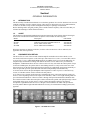
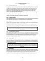
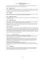
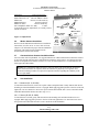
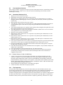
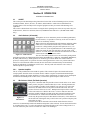
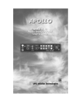
Apolloâ
Model SL10 Series Audio Selector Panel
Installation Manual
December 2001
560-0978-00
No part of this document may be reproduced in any form or by any means without the express written
consent of UPS Aviation Technologies, Inc.
UPS Aviation Technologies, Inc., II Morrow, and Apollo are trademarks of UPS Aviation Technologies,
Inc.
© 2001 by UPS Aviation Technologies, Inc. All rights reserved.
Printed in the U.S.A.
UPS Aviation Technologies, Inc.
2345 Turner Road, S.E. Salem, OR 97302
U.S.A. Toll Free
800.525.6726
Canada Toll Free
800.654.3415
International
503.391.3411
FAX
503.364.2138
Visit our web page at http://www.upsat.com
Send comments about this manual by email to: [email protected]
History of Revisions
Original Release December 2001 Rev. 00
Ordering Information
To receive additional copies of the Apollo SL10 Installation Guide, order part #560-0978-00 and for the
Apollo SL10 User’s Guide, order part #560-0975-00a.
UPS Aviation Technologies
SL10 Series Audio Selector Panel and Intercom System
Installation Manual
Table of Contents
Section I GENERAL INFORMATION................................................................................................ 1-1
1.1 INTRODUCTION......................................................................................................................... 1-1
1.2 SCOPE .......................................................................................................................................... 1-1
1.3 EQUIPMENT DESCRIPTION..................................................................................................... 1-1
1.4 APPROVAL BASIS - FAA .......................................................................................................... 1-2
1.5 SPECIFICATIONS ....................................................................................................................... 1-2
1.6 EQUIPMENT SUPPLIED ............................................................................................................ 1-3
1.7 EQUIPMENT REQUIRED BUT NOT SUPPLIED ..................................................................... 1-3
1.8 LICENSE REQUIREMENTS....................................................................................................... 1-3
Section II -Installation................................................................................................. 2-1
2.1 GENERAL INFORMATION ....................................................................................................... 2-1
2.1.1
SCOPE................................................................................................................................. 2-1
2.2 Unpacking and Preliminary Inspection ......................................................................................... 2-1
2.3 Equipment Installation Procedures................................................................................................ 2-1
2.3.1
Cooling Requirements ......................................................................................................... 2-1
2.3.2
Mounting Requirements ...................................................................................................... 2-1
2.3.3
Mounting Rack Installation ................................................................................................. 2-2
2.3.4
Connector Assembly............................................................................................................ 2-2
2.4 Cable Harness Wiring ................................................................................................................... 2-2
2.4.1
Noise.................................................................................................................................... 2-2
2.4.2
Entertainment Input ............................................................................................................. 2-3
2.4.3
External Push-to-Talk.......................................................................................................... 2-4
2.4.4
Transmit Interlock ............................................................................................................... 2-4
2.4.5
Power................................................................................................................................... 2-4
2.4.6
Existing KMA-24 Installation ............................................................................................. 2-4
2.4.7
"Swap" Mode....................................................................................................................... 2-4
2.4.8
Backlighting ........................................................................................................................ 2-4
2.4.9
Speaker Loads ..................................................................................................................... 2-5
2.4.10 PA Mute............................................................................................................................... 2-5
2.4.11 Middle Marker Sense........................................................................................................... 2-5
2.4.12 Unswitched Inputs ............................................................................................................... 2-5
2.4.13 Intercom............................................................................................................................... 2-5
2.5 Adjustments .................................................................................................................................. 2-5
2.6 Marker Antenna Installation.......................................................................................................... 2-6
2.7 Communications Antenna Installation Notes................................................................................ 2-6
2.8 Unit Installation............................................................................................................................. 2-6
2.9 Post Installation Checkout............................................................................................................. 2-7
2.9.1
Operational Checkout, SL10 ............................................................................................... 2-7
2.10
Final Inspection. ....................................................................................................................... 2-7
Section III OPERATION .................................................................................................................... 3-1
3.1 SCOPE .......................................................................................................................................... 3-1
3.2 Audio Selector (All models) ......................................................................................................... 3-1
3.2.1
Speaker Amplifier................................................................................................................ 3-1
3.3 Mic Selector Switch (Fail Safe Operation) ................................................................................... 3-1
3.3.1
Swap Mode (Switch from Com 1 to Com 2 remotely) ........................................................ 3-2
3.4 Split Mode..................................................................................................................................... 3-2
3.5 Intercom ........................................................................................................................................ 3-2
3.5.1
Volume Control, Monaural (SL10M SL10) ........................................................................ 3-2
3.5.2
Volume Control, Stereo, (SL10S, SL10MS) ....................................................................... 3-2
3.5.3
Adjusting the VOX-Squelch control, Monaural (SL10, SL10M)........................................ 3-3
3.5.4
Adjusting the VOX- Squelch control, Stereo (SL10S, SL10MS)........................................ 3-3
3.5.5
Intercom Modes (All versions) ............................................................................................ 3-3
UPS Aviation Technologies
SL10 Series Audio Selector Panel and Intercom System
Installation Manual
3.5.6
Push to talk intercom mode ................................................................................................. 3-4
3.6 Marker Beacon (SL10M, SL10M-S.............................................................................................. 3-5
3.6.1
Middle Marker Sense........................................................................................................... 3-5
3.6.2
External Marker Lights (SL10, SL10S)............................................................................... 3-5
3.6.3
Receiver Sensitivity............................................................................................................. 3-5
Section IV- Warranty and Service ...................................................................................................... 4-1
4.1 Warranty........................................................................................................................................ 4-1
4.2 Factory Service ............................................................................................................................. 4-1
Appendix A External PTT Hook Up.....................................................................................................A
Appendix B- Installation Drawing ......................................................................................................... B
Appendix D Top Connector wiring (Mono), SL10, SL10M..................................................................D
Appendix E Top Connector wiring, (Stereo) SL10S, SL10MS ............................................................. E
Appendix F -Instructions for Continuing Airworthiness and FAA Form 337 ................................... F
Appendix G RTCA DO160B Environmental Qualification Form .....................................................G
Table of Figures
Figure 1-1 SL10MS Stereo unit................................................................................................................... 1-1
Figure 2-1 Adjustments ............................................................................................................................... 2-6
Figure 3-1 Audio Selector ........................................................................................................................... 3-1
Figure 3-2 Mic Selector.............................................................................................................................. 3-1
Figure 3-3 Volume Controls Mono ............................................................................................................. 3-2
Figure 3-4 Volume Control Stereo .............................................................................................................. 3-2
Tables
Table 3-1 Intercom Modes .......................................................................................................................... 3-4
UPS Aviation Technologies
SL10 Series Audio Selector Panel and Intercom System
Installation Manual
Section I
GENERAL INFORMATION
1.1
INTRODUCTION
The SL10 family of Audio Selector Panels are revolutionary products. Never before has there been so much
capability and utility in such a compact package. These units are designed for ease of use and installation,
as well as to facilitate cockpit resource management and improve passenger entertainment.
Before installing and/or using this product, please read this manual completely. This will ensure that you
will take full advantage of all the advanced features.
1.2
SCOPE
This manual provides detailed installation and operation instructions for the UPS Aviation Technologies
SL10-series of Audio Selector Panel/Intercom Systems. This includes the following units:
Model
Description
Part Number
SL10
Audio Selector Panel
430-6060-10
SL10M
Audio Selector Panel with Marker Receiver
430-6060-20
SL10S
Stereo Audio Selector Panel
430-6060-30
SL10MS
Stereo Audio Panel with Marker
430-6060-40
Where the functions are identical to all units, it will be referred to herein as a SL10. Otherwise, the
applicable units will be specified.
1.3
EQUIPMENT DESCRIPTION
The SL10-series is a state of the art audio isolation amplifier and audio selector that contains a voice
activated (VOX) intercom system. It can switch up to three transceivers (Com 1, Com 2 and TEL) and six
receivers (Nav 1, Nav 2, ADF, DME, MKR and AUX). In addition, there are two unswitched inputs, for
telephone ringer and altimeter warning. Push buttons select the receiver audio source provided to the
headphones. A SPR button allows the user to listen to the receiver(s) selected on the cabin speaker. Except
for the unswitched inputs, all speaker audio is muted during transmit. A rotary switch selects one of the
three transceivers for the pilot and copilot position in transmit. In "Split Mode" the SL10 has the ability to
allow the pilot and copilot to operate different transmitters independently and simultaneously.
A fail-safe mode connects the pilot headphone and microphone to COM 1 if power is removed for any
reason, or if the Mic Selector switch is turned to the Off position.
A six-station voice activated (VOX) intercom is included in the SL10. pilot isolate and crew modes, two
mono (or stereo depending on unit) music inputs with "Soft Mute," and a 2-color Light Emitting Diode for
power and transmit indications. Intercom control is through front panel mounted knobs. Monaural units
have a dual concentric knobs that control pilot volume and intercom squelch, and copilot/passenger volume
and squelch. In the stereo versions, there is a single volume and squelch control for all on board.
An optional 3-light Marker Beacon receiver is integral to the SL10M and SL10MS. This provides the
necessary Marker Beacon light and audio indications necessary for an Instrument Landing System (ILS)
approach.
Figure 1-1 SL10MS Stereo unit
1-1
UPS Aviation Technologies
SL10 Series Audio Selector Panel and Intercom System
Installation Manual
1.4
APPROVAL BASIS - FAA
TSO Approval.
The SL10 and SL10S, Audio Selector Panels are FAA approved under TSO C50c (Audio Amplifiers).
The SL10M and SL10MS are FAA approved under TSO C50c and TSO C35d (Marker Beacon Receivers).
All systems comply with RTCA DO-143, DO-160b and DO-170.
Operation is subject to the following conditions:
1. This device may not cause harmful interference.
2. This device must accept any interference received, including interference that may cause undesired
operation.
1.5
SPECIFICATIONS
GENERAL SPECIFICATION
CHARACTERISTIC
TSO COMPLIANCE:
Marker Beacon:
C35d, Class A
Audio Selector/Intercom:
C50c, Class A
APPLICABLE DOCUMENTS: RTCA DO-160b, RTCA DO-170 and RTCA DO-143
ENVIRONMENTAL Qualifications:
A1D1/CAMXXXXXXXBBBBAAX
Temperature Range:
Operating: -20°C to +55°C
Storage: -40°C to +85°C
Altitude:
Up to 50,000 feet in an non-pressurized area of the cockpit.
DIMENSIONS: Height: 1.3 in. (3.3 cm) Width: 6.25 in. (16.9 cm) Depth: 6.8 in. (17.3 cm)
WEIGHT (With Rack & Connectors) :
1.5 Lb. (0.68 kg.)
POWER REQUIREMENTS (Including Internal Lighting):
Voltage:
13.75 or 27.5 VDC*
Maximum Current:
1 Amp (Externally protected by a 2 Amp circuit breaker.)
Typical operating current:
speaker off:
350 mA
speaker on:
600 mA
NOTICE: To reduce the amount of heat dissipated in the audio selector panel, when used in a 28
Volt aircraft, the 15 W, 15 Watt dropping resistor (P/N 701-015-1501) must be installed in series
with the power input.
Audio selector panel input impedance:
510 W
Input Isolation:
-70 dB (min.)
Speaker Muting:
-60 dB (min.)
Speaker Output (into 4 W):
3 Watts (min.) with no clipping
Switched Receiver Inputs:
8
(Com 1, Com 2, Nav 1, Nav 2, ADF, DME, MKR, AUX)
Unswitched Inputs:
2
(TEL Ringer, Altimeter DH)
Transmitter Selections:
5
(Com 1, Com 2, Com1/2, Com2/1, TEL/Com1)
Speaker Impedance:
4W
Headphone Impedance:
150 - 1000 W
Headphone Output:
45 mW each headset with no clipping
Microphone Impedance:
150 - 600 W
Intercom Positions:
6 places
Music Inputs:
2
Music Muting: >50 dB "Soft Mute" when Com or intercom active.
Distortion: <1% THD
@ 45 mW into 150W
Mic Freq. Response, ±3 dB:
350 Hz - 6000 Hz
Music Freq. Response, ±3 dB:
200 Hz - 15 kHz
MARKER BEACON RECEIVER: (SL10M, SL10MS, Only)
Frequency:
75 MHz Crystal Controlled
Sensitivity:
Low:
450 mVolts (Hard)
1-2
UPS Aviation Technologies
SL10 Series Audio Selector Panel and Intercom System
Installation Manual
Factory adjusted to 1400mV (Soft)
160 mVolts (Hard)
Factory adjusted to 150mV (Soft)
-6 dB at 110 kHz -40 dB at 120 kHz
9.0 (+/- 0.5) VDC Positive when active, max. current 125 mA
Active high (4.7 VDC +/- 0.5V) during Middle Marker
acquisition, for autopilot use.
High:
Selectivity:
External Lamp Output:
MM Sense:
1.6
A.
EQUIPMENT SUPPLIED
1 ea. of the following units:
Model
SL10
SL10S
SL10M
SL10MS
B.
SL10 Installation Kit:
Part Number
120-425-4402
120-425-4401
120-425-4400
425-001-0001
701-015-0015
200-066-0003
1.7
Description
Top Connector, Stereo (key 4/5)
Top Connector, Mono (key 2/3)
Bottom Connector (key 7/8)
Gold Plated Crimp Pins
15 Watt Dropping Resistor
(Recommended for 28 Volt Systems)
Operator's and Installation Manual
Quantity
Stereo
1
x
1
75
1
Quantity
Mono
x
1
1
75
1
1
1
EQUIPMENT REQUIRED BUT NOT SUPPLIED
A.
B.
C.
D.
E.
F.
G.
H.
1.8
None
Part Number
430-6060-10
430-6060-30
430-6060-20
430-6060-40
Speaker, 4 W
Headphones, 150 W stereo (SL10S) or mono (SL10MS), up to 6 as required
Microphones, up to 6 as required
Marker Antenna (75 MHz, VSWR <1:1.5, and appropriate for the airspeed)
Interconnect Wiring
Headphone Jacks (As Required)
Microphone Jacks (As Required)
Circuit Breaker: 1 ea. 2 amp.
LICENSE REQUIREMENTS
1-3
UPS Aviation Technologies
SL10 Series Audio Selector Panel and Intercom System
Installation Manual
Section II -Installation
2.1
GENERAL INFORMATION
2.1.1 SCOPE
This section provides detailed installation and interconnect instructions for the UPS Aviation Technologies
SL10-Series Audio Selector Panel/Intercom System and SL10M-Series Audio Selector Panel/Intercom
System with internal Marker Beacon.
With the exception of the internal marker beacon receiver, the SL10, SL10S, SL10C and SL10SC are
identical to the SL10M, SL10M-S, SL10M-C, SL10M-S-C. All units will be identified hereafter as the
SL10, where the information applies to all.
Please read this manual carefully before beginning any installation to prevent damage and post installation
problems. Installation of this equipment requires special tools and knowledge. The equipment must be
installed by an appropriately rated Certified Aircraft Repair Station, in accordance with applicable
regulations.
NOTE: The SL10-Series-S requires specialized knowledge and tools for an effective installation. An
appropriately rated Certified Aircraft Repair Station must install this equipment in accordance with
applicable regulations. UPS Aviation Technologies, warranty is not valid unless the equipment is installed
by an authorized UPS Aviation Technologies, dealer. Failure to follow any of the installation instructions,
or installation by a non-certified individual or agency will void the warranty, and may result in an
unairworthy installation.
2.2
Unpacking and Preliminary Inspection
Use care when unpacking the equipment. Inspect the units and parts supplied for visible signs of shipping
damage. Examine the unit for loose or broken buttons, bent knobs, etc. Verify the correct quantity of
components supplied with the list in Section 1.6 (B). If any claim is to be made, save the shipping material
and contact the freight carrier. Do NOT return units damaged in shipping to UPS Aviation Technologies. If
the unit or accessories shows any sign of external shipping damage, contact UPS Aviation Technologies to
arrange for a replacement. Under no circumstances attempt to install a damaged unit in an aircraft.
Equipment returned to UPS Aviation Technologies for any other reason should be shipped in the original
UPS Aviation Technologies packaging, or other UPS approved packaging.
2.3
Equipment Installation Procedures
2.3.1 Cooling Requirements
Forced air cooling of the SL10 is not required. However the unit should be kept away from heat producing
sources (i.e. defrost or heater ducts, dropping resistors, heat producing avionics) without adequate cooling
air provided.
NOTICE: To reduce the amount of heat dissipated in the audio selector panel, when used in a 28
Volt aircraft, it is required that the 15 W, 15 Watt dropping resistor (p/n 701-015-1501) be
installed in series with the power input.
If the SL10/M-S is installed in a 27.5 VDC aircraft system, a 15 W, 15 Watt dropping resistor (p/n 701-0151501) should be installed. Failure to do so will generate unnecessary heat inside the unit and may void UPS
Aviation Technologies's warranty.
2.3.2 Mounting Requirements
The SL10 must be rigidly mounted to the instrument panel of the aircraft structure and within view and
reach of the pilot position(s). Installation must comply with FAA Advisory Circular AC 43.13-2A. The unit
may be mounted in any area where adequate clearance for the unit and associated wiring bundle exist.
NOTE: The mounting hole configuration for the SL10 is identical to the KMA-24 Audio Selector
Panel. See Appendix B
2-1
UPS Aviation Technologies
SL10 Series Audio Selector Panel and Intercom System
Installation Manual
2.3.3
Mounting Rack Installation
2.3.3.1 Monaural (SL10, SL10M)
Remove the unit from the mounting tray by first removing the copilot volume and squelch knobs (the knobs
are press-fit on the shaft) and then unscrew the 3/32-inch hex-head screw that is to the right of the copilot
control knob shaft. Carefully slide the unit free of the tray. Set the unit aside in a safe location until needed.
Install the tray using six FHP 6-32 x ½-inch screws. The audio selector panel must be supported at front
and rear of the mounting tray.
2.3.3.2 Stereo (SL10S, SL10MS)
Remove the unit from the mounting tray by unscrewing the 3/32" hex-head screw that is to the right of the
squelch knob shaft. It is not necessary to remove the squelch knob. Carefully slide the unit free of the tray.
Set the unit aside in a safe location until needed. Install the tray using six FHP 6-32 x ½" screws. The
audio selector panel must be supported at front and rear of the mounting tray.
2.3.4 Connector Assembly
The unit connectors mate directly with the circuit boards in the SL10. The connectors are a Molex crimptype, and require the use of a Molex hand crimp tool, EDP P/N 11-01-0203, CR6115B (or equiv.). The
connector is mounted to the unit tray with #4-40 screws, from the inside of the tray. Ensure that proper
strain relief and chafing precautions are made during wiring and installation.
2.4
Cable Harness Wiring
Referring to appropriate Appendix C, D, E and F, assemble a wiring harness as required for the installation.
All wires must be MIL-SPEC in accordance with current regulations. Two- and three-conductor with shield
wire must be used where indicated, and be MIL-C-27500 or equivalent specification. Proper stripping,
shielding and soldering technique must be used at all times. It is imperative that correct wire be used.
Refer to FAA Advisory Circular 43.13-2A for more information. Failure to use correct techniques may
result in improper operation, electrical noise or unit failure. Damage caused by improper installation will
void the UPS Aviation Technologies warranty.
2.4.1 Noise
Due to the variety and the high power of radio equipment often found in today's general aviation aircraft,
there is a potential for both radiated and conducted noise interference.
The SL10 power supply is specifically designed to reduce conducted electrical noise on the aircraft power
bus by at least 50dB. Although this is a large amount of attenuation, it may not eliminate all noise,
particularly if the amplitude of noise is very high. There must be at least 13.0 VDC present at the bottom
connector, pin 20, of the SL10 for the power supply to work in its designed regulation. Otherwise, it cannot
adequately attenuate power line noise. Shielding can reduce or prevent radiated noise (i.e., beacon, electric
gyros, switching power supplies, etc.) However, installation combinations can occur where interference is
possible. The SL10s were designed in a RFI hardened chassis and have internal Electromagnetic
Interference (EMI) filters on all inputs and outputs.
Ground loop noise occurs when there are two or more ground paths for the same signal (i.e., airframe and
ground return wire). Large cyclic loads such as strobes, inverters, etc., can inject noise signals onto the
airframe that are detected by the audio system. Follow the wiring diagram very carefully to help ensure a
minimum of ground loop potential. Use only Mil Spec shielded wires (MIL-C-275000, or better). Under no
circumstances combine a microphone and headphone wiring into the same shielded bundle. Always use a
2- or 3-conductor, shield wire as shown on the installation wiring diagram.
Radiated signals can be a factor when low level microphone signals are "bundled" with current carrying
power wires. Keep these cables physically separated. It is very important that you use insulated washers to
isolate the ground return path from the airframe to all headphone and microphone jacks.
Adding a high-performance audio control system, particularly in conjunction with active noise canceling
headsets, cannot improve on older avionics that were designed for cabin-speaker use. UPS Aviation
Technologies makes no claim that the audio panel will provide a noise-free audio quality under all
installation conditions, particularly with older avionics.
2-2
UPS Aviation Technologies
SL10 Series Audio Selector Panel and Intercom System
Installation Manual
2.4.2
Entertainment Input
2.4.2.1 Monaural (SL10, SL10M)
Two entertainment devices (CD player, cassette player, etc.) can be connected to the unit. Install two 1/8inch stereo jacks in a convenient location so that the pilot can plug in the entertainment devices into the
system.
For a stereo input, we recommend tying the left and right channels (tip and ring) together, so both stereo
channels are provided to the monaural audio panel, and the audio amplitude available to the audio panel is
increased. Audio signal at the entertainment input must be a minimum of 500 mV P-P for optimum music
performance. We have noticed that the portable devices using 4 batteries seem to work better than the 2cell types. Also we have found that some cigarette-lighter adapters introduce noise into the system due to
the dropping power supply.
NOTE: The Sof t Mu te mu st be en ab led in th e SL10, SL10 M eith er b y
connecting top conn ecto r p ins N and 12 tog e ther in th e h arn ess, o r throug h an
ex tern al Soft Mu te En able switch.
2.4.2.2 Stereo (SL10S, SL10MS)
Two stereo entertainment devices (CD player, cassette player, etc.) can be connected to the unit. Install two
1/8-inch stereo jacks in a convenient location so that the pilot can plug in the entertainment devices into the
system. The audio signal at the entertainment input must be a minimum of 500 mV P-P per channel for
optimum music performance. We have noticed that the portable devices using 4 batteries seem to work
better than the 2-cell types. Also we have found that some cigarette-lighter adapters introduce noise into the
system due to the dropping power supply.
2.4.2.3 Soft Mute
The SL10-system incorporates a "Soft Mute" system. This will mute the entertainment devices during ICS
or radio traffic. While in the ALL or ISO modes, entertainment #1 is heard by everyone (except by the pilot
in ISO mode). While in the CREW mode, pilot and copilot will hear entertainment #1 while the passengers
will hear entertainment #2.
Entertainment inputs #1 and #2 can be paralleled so a single entertainment source can serve both the
passengers and the crew in "crew" mode. It is suggested however, that a switch (DPDT) be installed
between the single entertainment device and entertainment input #1. This will allow the pilot and copilot to
decide if they hear entertainment while in the Crew mode.
Local oscillators and internal signals from some entertainment equipment can cause undesired interference
with other aircraft systems. Before takeoff, operate the entertainment devices to determine if there is any
adverse effect within the aircraft systems. If any unusual operation is noted in flight, immediately switch
off the entertainment devices.
NOTE: U se the low level outpu t of any en ter tain men t dev ice to connect to th e
a ud io p ane l. Max imu m s igna l lev e l is 2 VAC p - p . D O NOT u s e a spe ak er - l e v e l
ou tpu t, th is will cause intern al d a ma g e in th e au dio pan e l.
To use a lin e level, in stall an Aud io L ink Pow er L ink 101PL2 adap ter , av ailab le
fro m Cru tch field at 1- 800-9 55-3 000
(804)-817 -1 000, sales@crutchf ield.co m
2.4.2.4 Soft Mute (Stereo only)
Entertainment #1 input has a "Soft Mute" inhibit switch that is part of the volume control located on the
front panel. By pressing it once, the entertainment device will not be muted, push it again and it will be
muted by intercom and radio conversation.
On SL10 stereo units with serial numbers above “G” series on the intercom board (second set of serial
numbers) have an Entertainment #2 Karoake mode capability. This "Soft Mute" inhibit switch is part of the
squelch control located on the front panel. By pressing it once, the entertainment device will not be muted,
push it again and it will be muted by intercom and radio conversation.
2-3
UPS Aviation Technologies
SL10 Series Audio Selector Panel and Intercom System
Installation Manual
2.4.3 External Push-to-Talk
An important part of the installation is the PTT (Push-To-Talk) switches that allow the use of your aircraft
communications radio for transmissions. There are three typical configurations that can be used. Select the
case that best fits the installation. Only the person who presses their PTT switch will be heard over the
radio. If the pilot and copilot both use the PTT, the copilot position has access to the radio. The pilot
position will have PTT control regardless of the copilot when the SL10 is in the FAIL-SAFE mode.
CASE I: PTT is built into both pilot and copilot yokes.
CASE II: PTT is in pilot yoke only. This configuration requires a modified external PTT switch plugged
into the copilot's microphone jack. (See Appendix A). When the copilot's PTT is pressed, the intercom
switches the mic audio from pilot to copilot mic.
CASE III: No built in PTT. This requires two built in PTTs to be installed, or modified external PTT
switches to be used. Modify external PTT as required (See Appendix A).
2.4.4 Transmit Interlock
Some communications transceivers use a transmit interlock system. In order to fully utilize the Split Mode
feature, this function must be disabled. Consult that manufacturer's installation manual.
2.4.5 Power
The SL10-Series are compatible with both 13.8 and 28 Volt DC systems. A two (2) Amp circuit breaker is
required. Power and ground wires must be a twisted #18 AWG pair.
Included with this product is a power dropping resistor to be connected in series with the power input,
bottom connector, pin 20. This dropping resistor is supplied for 28 volt systems so that unnecessary heat
dissipation inside the SL10 can be avoided.
NOTICE: To reduce the amount of heat dissipated in the audio selector panel, when used in a 28
Volt aircraft, a 15 W, 15 Watt dropping resistor (p/n 701-015-1501) must be installed in series with
the power input.
2.4.6 Existing KMA-24 Installation
If the installation replaces a KMA-24 (series -01, -02 or -03), the existing 44 pin connector can be used for
the bottom connector of the SL10 tray as it is, if it is properly installed and wired. A dropping resistor must
be in series with the power in a 28V KMA 24 installation. No other changes are required except for
external marker lights (see Section 3.7.2 for details). The "key" in the existing connector must be located
between pins 7 and 8. This connector will be used in the bottom connector position. (See appropriate
Appendix for complete wiring harness details.)
2.4.7 "Swap" Mode
When a normally-open, momentary, push-button switch is connected between pin 10 on the top connector
and aircraft ground, the user can switch between Com 1 and 2 by depressing this switch without having to
turn the mic selector switch. This yoke mounted switch eliminates the need of removing your hands from
the yoke to change transceivers.
NOTICE: Some older model radios may cause the Swap mode to activate on the release of the
PTT switch, due to the excessive back EMF from the collapsing relay coil field. Verify that back
EMF suppression, in the form of a diode across the T/R relay coil, is present if un-commanded
Swap occurs.
2.4.8 Backlighting
The SL10 has an automatic back-lighting system controlled by a photodetector. Additional control can be
gained by the aircraft avionics dimmer control. Connect the dimmer control line to bottom connector pin D
for 14 volt systems, and to bottom connector pin F for 28 volt systems. Pin E is light ground. This
installation provides the ability to bring the back-lighting level to zero. If dimmer control is not used, a
constant low level back light illumination has been established for night-time viewing. The photocell
2-4
UPS Aviation Technologies
SL10 Series Audio Selector Panel and Intercom System
Installation Manual
located at the lower right hand side of the unit face will automatically adjust the backlight of the pushbutton lamps as well as the rotary mic selector switch light intensity.
2.4.9 Speaker Loads
Certain VHF Nav/Comms, such as King KX170-series have internal speaker amplifiers. These are not used
with a SL10, but must be loaded to prevent unit failure. Connect the speaker output from the Nav/Com to
the appropriate load on the SL10 (bottom connector 19 and L for COM 1, etc).
2.4.10 PA Mute
Bottom connector pin 18 is a TTL logic output that is pulled low during PTT operation. This serves as an
input to external public address system to prevent feedback during transmissions.
2.4.11 Middle Marker Sense
The MM Sense output is connected to specific autopilots, and goes high only when a middle marker signal
is received, not in test.
2.4.12 Unswitched Inputs
The SL10 has two unswitched inputs. Bottom connector pin 17 is unswitched, but muted by transmissions.
This signal can be used for less critical inputs such as airborne telephone ringer.
Bottom connector pin T is an unswitched and unmuted audio input. This audio is always presented to the
headphones and speaker, regardless of the audio panel audio selections. This input can be use for critical
warnings, such as radio altimeter warnings.
2.4.13 Intercom
The top connector is for the intercom function. All mic and headphone jacks must have insulating washers,
the cable must be Teflon coated, twisted-shielded wire, and the shield must only be connected to the ground
return wire only at the intercom connector. NOTE: This harness can be custom made by UPS Aviation
Technologies, Inc. Simply call the factory and obtain a wire harness work-sheet. The harness will be made
to your specifications and fully functionally tested. All hardware is included. (See Appendix C (mono) and
E (stereo) for intercom connection configurations).
2.4.13.1
Push-to-talk intercom
SL10-series units with intercom board (second series of numbers on data plate) serial number above a “G”
series in stereo, or “MO series in mono, include a push-to-talk intercom capability.
In some extremely high noise environments, it may be desirable to have a push to talk (PTT) intercom,
instead of relying on voice-activation (VOX).
To operate the PTT, simply rotate the SL10 squelch control to maximum (fully CW). Grounding the
appropriate pin on the top connector through a momentary switch will open only that intercom channel.
The pilot and copilot are individually controlled (Top connector, pins 22 and 21, respectively). All
passenger mics are controlled with pin 20.
The same pins are used for both mono and stereo SL10 Systems.
This applies ONLY to units with applicable serial numbers. If a unit with serial number below that
indicated is installed in a position wired for the PTT, no damage will occur, only the ICS PTT function will
not function.
2.5
Adjustments
The SL10 is factory adjusted to accommodate the typical requirements for most aircraft configurations.
There are three adjustments however, that will allow the installer to tailor the specific functions. The
numbers correspond to identification numbers stamped on some trays.
2-5
UPS Aviation Technologies
SL10 Series Audio Selector Panel and Intercom System
Installation Manual
Adjustment
Clockwise Results In
Cabin Speaker Level
Increase Speaker Volume
Marker Beacon Level Decrease Marker Volume
MKR Gain
Increase overall sensitivity
MKR High Sense
Increase sensitivity
MKR Low Sense
Increase Sensitivity
Pass. Headphone (Mono or L & R)
Louder
To make the necessary adjustments, use a small jeweler's
slotted screwdriver.
Figure 2-1 Adjustments
2.6
Marker Antenna Installation
Refer to aircraft and antenna manufacturer's installation
instructions, as well as AC43.13-2A (or later revision),
Chapter 3, for information on proper antenna installation
techniques. The marker beacon antenna must be
mounted on the bottom of the aircraft.
MKR Hi Sense
(211)
MKR Audio Level
(233)
Cabin Speaker
Level (111)
Pass
Volume
Level
Mono
L (123)
R (113)
MKR Lo Sense
(231)
MKR Gain
(223)
2.7
Communications Antenna Installation Notes
For best results while in Split Mode, it is suggested that the one VHF communications antenna be located
on top of the aircraft while the other communications antenna be on the bottom. Any antenna relocation
must be accomplished in accordance with AC 43.13-2A, aircraft manufacturers’ recommendations and
FAA-approved technical data.
Warning: It is probable that radio interference will occur in the split mode when the frequencies
of the two aircraft radios are adjacent, and/or the antennas are physically close together. UPS
Aviation Technologies makes no expressed or implied warranties regarding the suitability of the
SL10 in Split Mode.
2.8
Unit Installation
2.8.1.1 Monaural (SL 10, SL10M)
To install the monaural SL10, remove the copilot volume and squelch knob. Gently slide the unit into the
mounting rack until the hold-down screw is engaged. While applying gentle pressure to the face of the unit,
tighten the 3/32" hex-head screw next to the copilot control shaft until the unit is secure. DO NOT OVER
TIGHTEN. Reinstall the knobs removed in step 2.3.3.1.
2.8.1.2 Stereo (SL10S, SL10MS)
To install the stereo SL10S, gently slide the unit into the mounting rack until the hold-down screw is
engaged. While applying gentle pressure to the face of the unit, tighten the 3/32" hex-head screw next to
the squelch control shaft until the unit is secure. DO NOT OVER TIGHTEN.
Wa rn ing : D o not over - tighten th e lo ck down scr ew wh ile installing th e u nit in
t r a y.
Internal damage will result.
2-6
UPS Aviation Technologies
SL10 Series Audio Selector Panel and Intercom System
Installation Manual
2.9
Post Installation Checkout
After wiring is complete, verify power is ONLY on pin 20 of the bottom connector, and airframe ground on
bottom connector pin Z. Failure to do so will cause serious internal damage and void UPS Aviation
Technologies's warranty.
2.9.1 Operational Checkout, SL10
1. Apply power to the aircraft and avionics.
2. Plug headsets into the pilot, copilot and passenger positions.
3. With avionics on, and the audio panel off, verify that the pilot can transmit and receive on COM 1,
through the headset, indicating proper “fail-safe” operation. On stereo units, the audio is present in the
right ear only.
4. Rotate the Mic Selector Switch to the Com 1 position.
5. Verify that the C1 light comes on. Verify that the power LED (Light Emitting Diode) in the intercom
section illuminates green. If the LED is red, stop testing and troubleshoot the microphone PTT
installation.
6. Verify proper transmit and receive operation on the copilot position, noting that the copilot PTT switch
allows proper transmission on the selected transceiver.
7. Verify that pushing the C2 button causes the button to illuminate, and the Com 2 receiver to be heard.
Verify operation on Com 1 from the pilot position.
8. Repeat for Com 2 and TEL, (if installed).
9. Rotate the mic selector switch to the COM 1/2 position. Verify that the pilot communicates on Com 1
and the copilot on Com 2.
10. Rotate the mic selector switch to the COM 2/1 position. Verify that the pilot communicates on Com 2
and the copilot on Com 1.
11. Rotate the mic selector switch to the TEL/COM 1 position. Verify that the pilot communicates on the
transceiver in the TEL position and the copilot on Com 1.
12. Verify proper operation of all receiver sources by selecting them using the keypad. Note that the button
for the receiver sources stays in, and the button illuminates to show which source is in use.
13. Push in the S (SPR) button. Verify that all selected audio is heard in the cockpit speaker. Verify that
the audio mutes when the mic is keyed.
14. Verify that the LED in the intercom is illuminated when a microphone is keyed. NOTE: LED does not
change color in "Split Mode".
15. Verify proper Intercom system operation in the ALL, ISO And CREW modes.
16. Verify that the audio selector panel system does not adversely affect any other aircraft system by
systematically switching the unit on and off, while monitoring the other avionics and electrical
equipment on the aircraft.
2.9.1.1 Marker Checkout, SL10M, SL10MS Only
1. Connect a ramp generator at the antenna end of the marker coax. With the unit under test in HI
sensitivity, verify that a 150 mVolts, modulated 95% with 1300 Hz signal will illuminate the amber
(M) marker light, and that marker audio is present in the headphones when the Marker Audio (M)
push-button has been depressed. Select "S" for speaker to verify marker audio availability on the cabin
speaker. Verify that the white (A) and blue (O) lights will illuminate within ± 3dB of the amber lamp,
with 3000 HZ and 400 Hz applied, respectively.
2. Repeat with the unit in LOW sensitivity, with 1400 mVolts applied.
3. Connect the marker antenna and verify proper operation.
2.10
Final Inspection.
Verify that the wiring is bundled away from all controls and no part of the installation interferes with
aircraft control operation. Move all controls through their full range while examining the installation to see
that no mechanical interference exists. Verify that the cables are secured to the aircraft structure in
accordance with good practices, with adequate strain relief. Ensure that there are no kinks or sharp bends in
the cables and coaxial cables. Verify that the cables are not exposed to any sharp edges or rough surfaces,
and that all contact points are protected from abrasion. Complete log book entry, FAA Form 337, weight
2-7
UPS Aviation Technologies
SL10 Series Audio Selector Panel and Intercom System
Installation Manual
and balance computation and other documentation as required. Return completed warranty registration
application to UPS Aviation Technologies.
2-8
UPS Aviation Technologies
SL10 Series Audio Selector Panel and Intercom System
Installation Manual
Section III OPERATION
GENERAL INFORMATION
3.1
SCOPE
This section provides detailed operating instructions for the UPS Aviation Technologies SL10, SL10S,
SL10M, SL10M-S, SL10C, SL10S-C, SL10M-C, and SL10M-S-C Audio Selector Panel/Intercom
Systems. Please read it carefully before using the equipment so that you can take full advantage of its
capabilities.
This section is divided into four sections covering the basic operating areas of the SL10 systems. They are:
Audio Selector, Transceiver Selection, Intercom, and Marker Beacon Receiver (SL10M and SL10MS
only).
3.2
Audio Selector (All models)
Through the use of two momentary and seven latched, push-button,
back-lit switches, it is possible to select any or all receiver audio. C1
and C2 are momentary switches.
When selected, an internal backlight will illuminate indicating which
audio source is selected. Because the rotary switch controls what
transceiver is being heard by the pilot and copilot (the crew), "Cl"
(Com 1) and "C2" (Com 2) push-buttons are of the momentary type
and do not remain in when selected. This is also part of the "auto
function." You will always hear the audio from the transceiver that is
selected by the rotary mic selector switch.
Figure 3-1 Audio Selector
The users can identify which receivers are selected by noting which
push-button switches are illuminated. Push buttons labeled Nl (Nav 1), N2 (Nav 2), D (DME), M (Marker),
A (ADF), AX (auxiliary), and S (Speaker) are "latched" type switches. When one of these buttons is
pressed, it will stay in the "in" position. Press the switch again and it be in the "out" position and remove
that receiver from the audio. While selected, the switch will also be annunciated by an internal lamp.
NOTE: In Split Mode, no pushbuttons will be active. The only audio selected is the com 1 and 2, as
indicated by their respective lamps.
3.2.1 Speaker Amplifier
The "S" in the push-button section stands for speaker. This switch will place all selected audio on the
cockpit speaker when this switch is selected. NOTE: with the exception of unswitched unmuted inputs
(Altimeter warning), the speaker amplifier is not active in the "Split Mode." To reduce power consumption
and internal heat buildup in the avionics stack, switch off the speaker amplifier when not in use.
3.3
Mic Selector Switch (Fail Safe Operation)
Unit power is turned on and off by the Mic selector switch. In the OFF or "FAILSAFE" position, the pilot is connected directly to Com 1 allowing transmit and
receive capability regardless of unit condition. Any time power is removed or
turned OFF, the audio selector will be placed in the fail-safe mode. The first
position clockwise from OFF is COM 1. Both pilot and copilot will be connected
to the Com l transceiver. While in the COM 1 or COM 2 mode, the intercom
functions normally. Both the pilot and copilot have transmit capabilities on the
selected transceiver. All hear the selected audio if the intercom is in the ALL
mode. Only the person who presses their Push To Talk (PTT), will be heard over
Figure 3-2
the aircraft radio. Turning the rotary switch to the COM 2 position will place pilot
Mic Selector
and copilot on Com 2.
The SL10-Series has an automatic selector mode. Audio from the selected
transceiver is automatically heard in the headsets and speaker (when selected). You can check this function
by switching from COM 1 to COM 2 and watch the selected audio light on the selector change from C1 to
C2. This ensures the pilot will never transmit on a radio is not listening to.
3-1
UPS Aviation Technologies
SL10 Series Audio Selector Panel and Intercom System
Installation Manual
In SL10-series units, Serial Number T03092 and above, when switching the mic selector rotary switch
from COM 1 to COM 2, while COM 2 audio had been selected, Com 1 audio will continue to be heard. This
eliminates the pilot having to switch Com 1 audio back on, if desired.
When switching from COM 1 to COM 2 while Com 2 has NOT been selected, Com 1 audio will be switched
off. In essence, switching the mic selector will not effect the selection of Com audio.
Important: When the mic selector is in the full counter clockwise position, the SL10 power is removed,
and it is in the FAIL-SAFE mode. The pilot headset and microphone is connected directly to Com 1.
3.3.1 Swap Mode (Switch from Com 1 to Com 2 remotely)
With a yoke mounted, momentary switch, the pilot can change from the current Com transceiver to the
other by depressing this switch. When "Swap Mode" is active, an LED annunciator will illuminate,
indicating that the Mic Selector switch position is no longer valid. To cancel "Swap Mode," the pilot may
either press the yoke mounted switch again, or turn the Mic Selector Switch to the Com that is active.
3.4
Split Mode
Turning the rotary switch to COM 1/COM 2 places the SL10 into "Split Mode". This places the pilot on Com
1 and the copilot on Com 2. Pilot and copilot are isolated from each other on the intercom, but can use their
respective radios simultaneously. An example of this useful feature is when the pilot may want to talk to
Air Traffic Control, while the copilot may be speaking to Flight Watch.
The "Split Mode" radio selection can be reversed by switching to COM 2/COM l. The pilot will be on Com 2
and the copilot will be on Com 1. A third "Split Mode" selection is TEL/COM l. This will place the pilot on
airborne radiotelephone, HF or other transceiver (if installed), while the copilot will be on Com 1.
Note: In all SL10s, Split Mode turns off all other (Nav, ADF, etc.)selected audio to pilot and
copilot. Additionally, there is no intercom function between pilot and copilot. Passengers still have
intercom capability among themselves.
3.5
Intercom
3.5.1
Volume Control, Monaural (SL10M SL10)
The pilot volume control knob adjusts the loudness of intercom and
music in the pilot’s headphones only. It has no effect on selected
radio audio levels. The copilot volume control adjusts the loudness
of the intercom and music in the copilot headset only. The
passenger volume is factory set at a comfortable level. This is a
service adjustment that can be accessed by the avionics technician.
Most general aviation headsets have a built-in volume control, so
volume can be adjusted “locally.”
Figure 3-3 Volume Controls
Figure 3-4 Volume Control Stereo
3.5.2 Volume Control, Stereo, (SL10S, SL10MS)
The volume control knob adjusts the loudness of the intercom and
music for the pilot and copilot only. It has no effect on selected
radio levels or passengers' level. The passenger volume level is
factory set for a comfortable listening level. Most general aviation
headsets today have a built-in volume controls, therefore, volume
can be adjusted at the headset. There is a service adjustment that
can be accessed by the avionics technician. This will allow
adjustment of the passenger's volume for a comfortable listening
level.
3-2
UPS Aviation Technologies
SL10 Series Audio Selector Panel and Intercom System
Installation Manual
3.5.2.1 Mono headsets in Stereo Installation
All passenger headsets are connected in parallel. Therefore, if a monaural headset is plugged in to a SL10
Stereo installation, one channel will be shorted. Although no damage to the unit will occur, all passengers
will lose one channel.
3.5.3 Adjusting the VOX-Squelch control, Monaural (SL10, SL10M)
The SL10 provides adjustable VOX squelch controls for the pilot and copilot (the copilot's VOX control
also adjusts the passengers VOX squelch) Since the number of microphones open at any one time is
reduced, the amount of background noise is diminished. This also allows the use of dissimilar headsets with
the same intercom. The user can adjust the trip level of the VOX to fit the individual's voice and mic, which
helps eliminate the frustration of clipping the first syllables.
With the engine running, set the VOX control knob by slowly rotating the SQL control knob clockwise until
you no longer hear the engine noise in the headphones. When the microphone is positioned properly near
your lips, normal speech levels should open the channel. When you have stopped talking, there is a delay
of about ½ second before the channel closes. This helps prevent choppy communications.
3.5.4 Adjusting the VOX- Squelch control, Stereo (SL10S, SL10MS)
The stereo versions of the SL10 incorporate a single VOX Squelch control for all positions. Like all UPS
Aviation Technologies intercoms, since the number of microphones active at any one time is reduced, the
unwanted background noise in the headphones is diminished. This also allows the use of dissimilar
headsets with the same intercom.
With the engine running, set the VOX trip level by slowly rotating the SQUELCH control knob clockwise
until you no longer hear the engine noise in the headphones. When the microphone is positioned properly
near your lips, normal speech levels should open the channel. When you have stopped talking, there is a
delay of about ½ second before the channel closes. This prevents closure between words and prevents
choppy communications.
3.5.5 Intercom Modes (All versions)
The center switch is a 3-position mode switch that allows the pilot to tailor the intercom function to best
meet the situation. The description of the intercom mode function is valid only when the unit is either in the
COM 1 or COM 2 position of the Mic Selector switch. When the unit is in the "Split" mode, only the
passengers have intercom function.
ISO: (Up Position): The pilot is isolated from the intercom and is connected only to the aircraft radio. He
will hear the aircraft radio reception (and sidetone during radio transmissions). Copilot and passengers will
hear the intercom and music on Entertainment 1, but not the aircraft radio receptions or pilot transmissions.
ALL: (Middle Position): All parties will hear the aircraft radio, intercom, and music from entertainment
input #1. However, during any intercom communications, the music volume automatically decreases when
SoftMute is active (See section 3.6.5.1). The music volume increases gradually back to the original level
after communications have been completed.
CREW (Down Position): Pilot and copilot are connected on one intercom channel and have exclusive
access to the aircraft radios. They may also listen to Entertainment 1. Passengers can continue to
communicate with themselves without interrupting the Crew and also may listen to Entertainment 2.
Anytime the SL10 is in either the COM 1/COM 2, COM 2/COM 1, or TEL/COM 1, ("Split Mode") the pilot and
copilot do not have any intercom function. The passengers will maintain intercommunications.
3.5.5.1 Soft Mute (Mono)
Soft Mute must be enabled during installation by jumpering top connector pins 12 and N. A SPST switch
can be installed between these pins for a pilot selectable mute mode. Without this connection, music is not
muted during intercom activation. This “Karaoke Mode” prevents the music muting when a sing-along is
desired. "Soft Mute" mode only applies to entertainment input #1. Entertainment #2 does not mute.
3-3
UPS Aviation Technologies
SL10 Series Audio Selector Panel and Intercom System
Installation Manual
3.5.5.2 Soft Mute (Stereo)
Both entertainment devices have the "Soft Mute" mode. In units earlier than a “G” intercom board serial
number (second set of numbers), only entertainment input #1 has the mute inhibit capability. "Soft Mute"
mode for the Crew positions (Entertainment 1) can be selected by pressing in the Volume control knob
once. In later units the SQL knob controls the Soft Mute of the passengers entertainment (#2).
3.5.5.3 Entertainment Input
The audio selector panel has provisions for up to two separate entertainment input devices. Which device is
heard is determined by the position of the three position mode switch located in the center of the intercom
section of the audio panel. (See Table 3-1 for overview.)
While in the ISO (Isolate) mode, only the copilot and the four passengers will hear entertainment device #1.
In normal operation, whenever a person speaks or if the aircraft radio becomes active, the music will
automatically mute and then will gradually return to the original listening level when the intercom or radio
activity ceases.
Which entertainment device will be heard is determined by the mode selector switch. When in the ALL
mode, all parties will hear the entertainment input #1. While in the CREW mode, pilot and copilot will hear
entertainment input #1 while the passengers may listen to entertainment input #2.
It is also possible to use only one entertainment input device for both entertainment inputs. It is suggested
however, that a switch (DPDT) be installed between the single entertainment device and entertainment
input #1. This will allow the pilot and copilot decide if they hear entertainment while in the Crew mode.
Table 3-1 Intercom Modes
Mode
Isolate
Pilot Hears
A/C Radio
Pilot Sidetone
(during radio
transmission)
Copilot Hears
Copilot and passenger
intercom
Entertainment #1
Passenger Hears
Passenger and Copilot
intercom
Entertainment #1
All
Pilot
Copilot
A/C Radio
Passengers
Entertainment #1
Copilot
Pilot
A/C Radio
Passengers
Entertainment #1
Passengers
Pilot
Copilot
A/C Radio
Entertainment #1
Crew
Pilot
Copilot
A/C Radio
Entertainment #1
Copilot
Pilot
A/C Radio
Entertainment #1
Passengers
Entertainment #2
Comments
This mode allows the
pilot to communicate
with the ground without
the copilot or passengers
bothered by the
conversations. Copilot
and passengers can
continue to communicate
and listen to music
This mode allows all on
board to hear radio
reception as well as
communicate on the
intercom. Music and
intercom is muted during
intercom and radio
communications
A second music source
is automatically enabled
for the passengers.
3.5.6 Push to talk intercom mode
SL10-series audio selector/intercom systems with serial number beginning with the letter “M” (monaural
version) or “G” (stereo version).
In some extremely high noise environments, it may be desirable to have a push to talk (PTT) intercom,
instead of relying on voice-activation (VOX).
In SL10 series with later configuration boards, the PTT intercom capability is added. To operate the PTT,
simply rotate the SL10 squelch control to maximum (fully CW). Grounding the appropriate pin on the top
connector through a momentary switch will open only that intercom channel. The pilot and copilot are
individually. All passenger mics are controlled with pin 20.
The same pins are used for both mono and stereo SL10 Systems. This applies ONLY to units with
applicable serial numbers.
3-4
UPS Aviation Technologies
SL10 Series Audio Selector Panel and Intercom System
Installation Manual
3.6
Marker Beacon (SL10M, SL10M-S
The optional Marker Beacon Receiver uses visual and audio indicators to alert you when the aircraft passes
over a 75 MHz transmitter.
The Blue lamp, labeled "O," is the Outer Marker lamp and has an associated 400 Hertz 'dash' tone. The
lamp and tone will be keyed at a rate of two tones/flashes per second when the aircraft is in the range of the
Outer Marker Beacon.
The Amber lamp, labeled "M," is the Middle Marker lamp and is coupled with a 1300 Hertz tone. It is
keyed alternately with short 'dot' and long 'dash' bursts at 95 combinations per minute.
The White lamp, labeled "A," is the Airway/Inner marker and has a 3000 Hertz 'dot' tone. The lamp and
tone will be keyed at a rate of six times per second.
The audio from the Marker Beacon Receiver can be heard by selecting the "M" push-button switch. To
adjust the volume level, there is a service adjustment located on the top of the unit. See Section 2.5
A 3-position switch is used to set the receiver sensitivity and to test the indicator lamps. Use "HIGH"
sensitivity initially. This allows you to hear the outer marker beacon about a mile out. Then select the
“LOW” sensitivity to give you a more accurate location of the Outer Marker. The momentary down switch
position is labeled "TEST" and illuminates all three lamps simultaneously to assure the lamps are in working
order.
Upon first application of power to the unit, the Marker enters a self test mode. The flickering blue marker
light indicates a test in process. If the test continues for more than 10 seconds, or the lamps do not
extinguish, return the unit for service.
3.6.1 Middle Marker Sense
A Middle Marker sense output signal is available to automatically reduce the autopilot sensitivity after the
aircraft has passed over the Middle Marker. This function will not operate during the test mode. This output
will go to +4.75 VDC (± 0.25 VDC) when a valid Middle Marker signal is received.
3.6.2 External Marker Lights (SL10, SL10S)
For installations that require external marker beacon lights, there are three outputs that can drive 12 Volt
lamps only. The external output lamps are driven high (+9 VDC ±0.5 VDC) when active. Maximum
source current per lamp is 125 mA.
If using an external marker receiver, the audio input is lower connector, pin 11 (Aux. input).
3.6.3 Receiver Sensitivity
Although the SL10M meets FAA TSO-C35d sensitivity specifications, the sensitivity of the receiver has
been adjusted to meet real world requirements (150mV and 1400mV Soft). This will usually eliminate the
need for the avionics shop to reduce the sensitivity in the field so as to prevent early detection of the marker
beacons. If your particular installation requires more or less sensitivity, please call the factory for details on
how to adjust the receiver sensitivity in the field.
3-5
UPS Aviation Technologies
SL10 Series Audio Selector Panel and Intercom System
Installation Manual
Section IV- Warranty and Service
4.1
Warranty
In order for the factory warranty to be valid, the installations in a certified aircraft must be accomplished by
an FAA-certified avionics shop and authorized UPS Aviation Technologies dealer. If the unit is being
installed by a non-certified individual in an experimental aircraft, a factory-made harness must be used for
the warranty to be valid. This harness may be purchased directly from PS Engineering (865-988-9800).
UPS Aviation Technologies. warrants this product to be free from defect in material and workmanship for a
period of 26-months from the date of installation as recorded in aircraft logbook and/or on FAA Form 337.
UPS Aviation Technologies, Inc. warrants this product to be free from defect in material and workmanship
for a period of 26-months from the date of installation. During this 26-month warranty period, UPS
Aviation Technologies, Inc. at its option, will send a replacement unit at our expense if the unit should
display any unusual behavior.
All transportation charges for returning the defective units are the responsibility of the purchaser. All
domestic transportation charges for returning the exchange or repaired unit to the purchaser will be borne
by UPS Aviation Technologies, Inc. The risk of loss or damage to the product is borne by the party making
the shipment, unless the purchaser requests a specific method of shipment. In this case, the purchaser
assumes the risk of loss. This warranty is not transferable. Any implied warranties expire at the expiration
date of this warranty. UPS Aviation Technologies SHALL NOT BE LIABLE FOR INCIDENTAL OR
CONSEQUENTIAL DAMAGES. This warranty does not cover a defect that has resulted from improper
handling, storage or preservation, or unreasonable use or maintenance as determined by us. This warranty
is void if there is any attempt to dissemble this product without factory authorization. This warranty gives
you specific legal rights, and you may also have other rights, which may vary from state to state. Some
states do not allow the exclusion of limitation of incidental or consequential damages, so the above
limitation or exclusions may not apply to you.
All items repaired or replaced under this warranty are warranted for the remainder of the original warranty
period. UPS Aviation Technologies, Inc. reserves the rights to make modifications or improvements to the
product without obligation to perform like modifications or improvements to previously manufactured
products.
4.2
Factory Service
The unit is covered by a 26-month limited warranty. See warranty information. Call UPS Aviation
Technologies, Inc. at (800) 525-6726 before you return the unit. This will allow the service technician to
provide any other suggestions for identifying the problem and recommend possible solutions.
After discussing the problem with the technician and you obtain a Return Authorization Number, ship the
product to:
UPS Aviation Technologies, Inc.
2345 Turner Road, S.E.
Salem, OR 97302
U.S.A. Toll Free 800.525.6726
4-1
UPS Aviation Technologies
SL10 Series Audio Selector Panel and Intercom System
Installation Manual
Appendix A
External PTT Hook Up
Part of the installation includes the installation of PTT (Push To Talk) switches that allow the use of your
aircraft radio for communications transmissions.
There are three configurations that can be used, you must select the case that best fits your installation.
NOTE: Only the person who presses their PTT switch will be heard over the radio.
CASE I
The PTT is built into the pilot and copilot yokes
Simply install the plugs from the headset into the aircraft headphone jacks. Then use the yoke mounted
PTT to transmit. No other action is required.
CASE II
Built in PTT only on the pilot side only
This configuration requires a modified external PTT switch plugged into the copilot's mic jack. (See Details
Below) When the copilot's PTT is depressed, this activates an internal relay that switches the mic audio to
the aircraft radio from the pilot to the copilot.
Case III
No built in PTT switch at all.
Two built-in PTT must be installed, or two external, modified PTT switches will be required for both the
pilot and copilot. Modifications to the PTT are required. (See details below)
Push To Talk Modifications
When received from the manufacturer, an after-market PTT switch opens the mic audio path to the "ring"
connection of the PTT mic plug until the button is pressed. When the PTT is between the intercom and the
headset, the intercom function will not work unless the PTT switch is depressed. A simple modification can
be performed to allow proper intercom operation. NOTE: This mod does not alter normal operation.
Below are some examples of typical modifications. Contact UPS Aviation Technologies or the PTT
manufacturer for more details if necessary.
Procedures For David Clark PTT
1.
2.
3.
Unscrew the round black plastic cover from the jack.
Connect the joined black wires to the red wire.
Replace the round black plastic cover.
Procedures for Telex PT-200
1.
2.
3.
4.
5.
Unscrew the round black plastic cover from the jack.
Cut the red wire in the middle of the wire.
Strip both ends of the insulation.
Solder the two ends to the ground lug to the PTT jack.
Replace the round black plastic cover.
Procedures for Telex PT-300
1.
2.
3.
4.
Unscrew the round black plastic cover from the plug jack.
Remove the heat shrink material from the joined black wires.
Solder these two wires to the lug that has a white wire already soldered to it.
Replace the round black plastic cover
A
UPS Aviation Technologies
SL10 Series Audio Selector Panel and Intercom System
Installation Manual
Appendix B- Installation Drawing
Cutout size for front mount installation
1.62 in
(41.15 mm)
6.31in (160.3 mm)
6.65 in (167 mm)
Side View
0.60 in (15.25 mm)
CG
0.35 in
(8.9 mm)
1.31 in
(33.27 mm)
3.00 in (76.2 mm)
5.25 in
(133.4 mm)
0.8 in
(20.3 mm)
6.28 in
(159.5 mm)
Rear View
Weight: 1.5 lb with tray and connectors ( .68 kg)
Connector viewed from the rear
Z Y XW V U T S R P N M L K J H F E D C B A
J2 (top)
22 21 20 19 18 17 16 15 14 13 12 11 10 9 8 7 6 5 4 3 2 1
Z Y XW V U T S R P N M L K J H F E D C B A
J1 (bottom)
22 21 20 19 18 17 16 15 14 13 12 11 10 9 8 7 6 5 4 3 2 1
B
UPS Aviation Technologies
SL10 Series Audio Selector Panel and Intercom System
Installation Manual
Appendix C Bottom Connector wiring, Mono and Stereo (see note 9)
BOTTOM CONNECTOR
9
Com 1 Audio Hi
Communications
Transceiver #1
Com 1 Lo
Com 1 Mic Audio Hi
Com 1 Mic Key
Com 1 Spr Load
Com 1 Spr Load
Com 1 SPR Load
See Notes 6, 8
10
Com 2 Audio Hi
Communications
Transceiver #2
P
R
19
L
Com 2 Lo
Com 2 Mic Audio Hi
Com 2 Mic Key
Com 2 SPR Load
Com 2 Spr Load
Com 2 Spr Load
Communications
Transceiver #3
(HF/TEL)
Com 3 Mic Audio Hi
Com 3 Audio Hi
H
V
16
M
J
Com 3 Lo
Com 3 Mic Key
Com 3 SPR Load
K
15
Com 3/HF Spr Load
Com 3/HF Spr Load
14
N
Nav 1 Audio Hi
NAV 1 Audio Lo
12
VHF Nav 1
VHF Nav 2
Nav 2 Audio Hi
Nav 2 Audio Lo
13
ADF Receiver
ADF Audio Hi
ADF Audio Lo
S
DME Receiver
DME Audio Hi
DME Audio Lo
6
AUX Audio Hi
AUX Audio Lo
11
Unswitched Audio #1
Unswitched Input #1 Hi
Unswitched Audio Lo
T
Unswitched Audio #2
Unswitched Input #2 Hi
Unswitched Audio Lo
17
See Note 11
AUX (MKR) Audio
8
Y
Pilot Mic Audio Hi
Pilot Mic PTT
Pilot Mic Lo
Pilot PTT
Pilot Phones (R)
Pilot Phones (L)
Pilot Phones Lo
3
Speaker Hi
W
22
Ext. Marker Annunciator
See Note 2
Speaker Lo
Ext. Marker Lamp (White)
White Lamp Output
C
Ext. Marker Lamp (Blue)
Blue Lamp Output
5
Ext. Marker Lamp (Amber)
Amber Lamp
4
MM Sense
2
MM Sense Output
MKR Ant.
B
A
F
D
E
18
RG-58A/U Coax
28 Volt Lights Hi
14 V Lights Hi
See Note 5
Lights Lo
PA Mute Trigger
11-33 VDC
2A
See Note 3, 7
20
15 ohm 15W
Ground Lug
Airframe Ground
Notes:
1. All shields should be grounded at audio panel only.
other end remains floating.
2. Speaker and Pilot Headphone ground returns
MUST be kept separate and connected
to pin 22.
3. All Power and Ground wires must be #18 gage wire
4. Pilot mic and headphone jacks must be isolated from ground.
5. PA Mute is a TTL level logic output
that is pulled low when PTT active.
6. Speaker loads may be reqired on some transceivers.
Consult manufacturer's information.
7. 28V installations require 15 ohm, 15W dropping
resistor.
8. All shielded wires must be MIL 22750 or 27500.
9. For mono versions (SL10, SL10M) connect pilot
headphone to pin 3 with 2-conductor wire.
For stereo versions (SL10S and SL10MS) connect
pilot headphone (L) to top connector, Pin 1,
using 3-conductor wire.
10. Key pin between pin 4 and 5.
11. For SL10 without marker, marker audio can be
interfaced through pin 11 (aux), and will
appear when M button pushed.
12. Marker Lamp outputs (C, 5, 4) go to +9 VDC, +/- 2VDC
at maximum bright, unlaoded) when active.
13. MM Sense output (pin 2) goes high when middle
marker signal received.
14. Pin T is unswitched, unmuted input
1
Z
C
To Pin 1
Top Conn.
See Note 9
UPS Aviation Technologies
SL10 Series Audio Selector Panel and Intercom System
Installation Manual
Appendix D Top Connector wiring (Mono), SL10, SL10M
Top Connector (monaural)
3
C
Copilot Phones Hi
Notes:
Copilot Phones Lo
1
Pass. Phones Hi
A
Pass. Phones Lo
5
E
Pass. Mic Hi
6
F
Pass. Mic Hi
7
H
Pass. Mic Hi
8
J
Pass. Mic Hi
1. All shields should be grounded at audio panel only.
other end remains floating.
2. All phone and mic jacks must be floating from ground.
3. All wiring to conform to MIL 22750 or 27500.
4. If the Soft Mute inhibit switch is not installed,
install a jumper between pins 12 and N.
Pass. 1 PhonesJack
No Connection
Pass. 1 Mic Jack
Pass. Mic Lo
No Connection
Pass. Mic Lo
Pass. 2 Mic Jack
Pass. 2 Phones Jack
Pass. 3 Mic Jack
Pass. 3 Phones Jack
Pass. 4 Mic Jack
Pass. 4 Phones Jack
No Connection
Pass. Mic Lo
Pass. Mic Lo
12
Soft Mute Inhibit Switch
N
9
10
K
4
D
Copilot Mic Audio
Copilot Mic Jack
Copilot Copilot PTT
Copilot Mic Lo
Ent. #1 Audio Hi
Ent. #1 Input
Ent. #1 Audio Lo
2
B
Ent. #2 Audio Lo
11
Swap
Ent. #2 Audio Hi
Ent. #2 Input
Swap
Switch
D
UPS Aviation Technologies
SL10 Series Audio Selector Panel and Intercom System
Installation Manual
Appendix E Top Connector wiring, (Stereo) SL10S, SL10MS
TOP CONNECTOR (Stereo)
Pilot Phones (L) -see bottom connector.
1
3
2
B
Copilot Phones Lo
Pass. Phones (R)
4
D
Pass. 1 Mic Hi
5
E
Pass. 2 Mic Hi
6
F
Pass. 3 Mic Hi
7
H
Pass. 4 Mic Hi
16
15
T
14
13
R
10
1. All shields should be grounded at audio panel only.
other end remains floating.
2. All phone and mic jacks must be floating from ground.
3. All wiring to conform to MIL 22750 or 27500.
Copilot Phones (L)
11
12
N
8
9
K
Notes:
Copilot Phones (R)
Pass. 1 Phones Jack
Pass Phones (L)
Pass. Phones Lo
Pass. 1 Mic Jack
Pass. 1 Mic Lo
Pass. 2 Mic Lo
Pass. 3 Mic Lo
Pass. 4 Mic Lo
Pass. 2 Mic Jack
Pass. 2 Phones Jack
Pass. 3 Mic Jack
Pass. 3 Phones Jack
Pass. 4 Mic Jack
Pass. 4 Phones Jack
Copilot Mic Audio
Copilot Mic Jack
Copilot Copilot PTT
Copilot Mic Lo
Copilot PTT
Ent. #1 Audio (L)
Ent. #1 Input
Ent. #1 Audio (R)
Ent. #1 Audio Lo
Ent. #2 Audio (L)
Ent. #2 Audio (R)
Ent. #2 Input
Ent. #2 Audio Lo
Swap
Swap
Switch
E
UPS Aviation Technologies
SL10 Series Audio Selector Panel and Intercom System
Installation Manual
Appendix F -Instructions for Continuing Airworthiness and FAA
Form 337
Sample ICA Checklist for UPS Aviation Technologies Audio Panels:
Section
1
Introduction
Item
2
Description
3
4
5
6
Controls
Servicing
Maintenance Instructions
Troubleshooting
7
Removal and replacement
information
8
9
10
11
12
13
14
15
16
Diagrams
Special Inspection Requirements
Protective Treatments
Structural Data
Special Tools
Not Applicable
Recommended Overhaul Periods
Airworthiness Limitations
Revision
Information
Installation of audio control panel with integrated marker beacon receiver and
intercommunications system.
Installation as described in manufacturer’s installation manual referenced on
FAA Form 337, including interface with other avionics audio as required.
See installation and operator’s guide referenced on FAA Form 337.
None Required
On Condition, no special instructions
In the event of a unit problem, place the unit into “OFF,” the fail-safe mode.
This allows pilot communications using COM 1. Follow checkout instructions
in the installation manual referenced on the FAA Form 337. For a specific unit
fault, contact the manufacturer at (865) 988-9800 for special instructions.
Removal: Using a 3/32” Allen-head wrench, carefully unscrew the locking
screw located in the center of the unit. While turning the wrench CCW, gently
pull on the EDGES of the bezel until the unit is free from the mounting tray.
Installation: Engage the locking screw at the back. Turn the locking screw CW,
while applying slight pressure to the edges of the bezel. Do not over tighten!
Not applicable
Not Applicable
Not Applicable
Not Applicable
None
Not Applicable
None
Not Applicable
To be determined by installer
Example for FAA Form 337
One method of airworthiness approval is through an FAA Form 337, Major Repair and Alteration
(Airframe, Powerplant, Propeller, or Appliance) In the case of the PM6000 audio panel you may use the
following text as a guide.
Installed 6-place intercom/audio selector panel, UPS Aviation Technologies SL10MS, part
number 430-6060-30 in center stack instrument panel location designated for panel mounted
avionics at station
. Installed per AC43.13-2, Chapter 2, paragraph 23 (Instrument Panel
Mounting). Installed per UPS Aviation Technologies Installation Operators Manual p/n
_____________), revision X, dated (xx-xx).
This unit is FAA-Approved under TSO C50c for audio amplifiers, and TSO C35d for Maker
Beacon Receivers, and meets environmental tests outlined in RTCA DO-160B as appropriate or
this aircraft.
Interface to existing aircraft radios in accordance with installation manual and in compliance with
practices listed in AC43.13-2, Chapter 2. All wires are Mil-Spec 22759 or 27500. Connection to
the aircraft dimmer bus is accomplished per the installation manual and
. Power is supplied to the unit through a 1A circuit breaker (type and part number), and total
electrical load does not exceed
% of the electrical system capacity with the SL10 added.
Aircraft equipment list, weight and balance amended. Compass compensation checked. A copy of
the operation instructions, contained in UPS Aviation Technologies document 200-066-(xxxx),
revision x, Dated ( ), is placed in the aircraft records. All work accomplished listed on Work
Order
.
F
UPS Aviation Technologies
SL10 Series Audio Selector Panel and Intercom System
Installation Manual
Appendix G RTCA DO160B Environmental Qualification Form
Audio Selector Panel/Intercom/Marker Beacon Receiver
Part Number: 6000, 6000M, 6000MC, SL10S, SL10MS 6000M-S-C
FAA TSO Number: C50c, C35b Class A
Manufacturer: PS Engineering Incorporated 9800 Martel Road
Lenoir City TN 37772
Conditions
Conducted Tests
Section
Temperature and Altitude
Low Temperature
High Temperature
Altitude
Temperature variation
Humidity
Shock
Operational
Crash Safety (Impulse)
Crash Safety (Sustained)
Vibration
Explosion
Waterproofness
Fluids Susceptibility
Sand and Dust
Fungus
Salt Spray
Magnetic Effect
Power input
Voltage Spike
Audio Frequency
Susceptibility
Induced Frequency
Susceptibility
Radio Frequency
Susceptibility
Radio Frequency Emission
Lightning Induced Transient
Susceptibility
Equipment tested to CAT A1
4.0
4.5.1
4.5.2
4.6.1
Equipment tested to CAT D1
5.0
6.0
7.0
7.2.1
7.3.1
7.3.2
8.0
9.0
10.0
11.0
12.0
13.0
14.0
15.0
16.0
17.0
18.0
Equipment tested to Category C
Equipment tested to Category A
Equipment tested to DO-160B, Par 7.1.1
Equipment tested to Category M, Standard
Category X, not tested
Category X, not tested
Category X, not tested
Category X, not tested
Category X, not tested
Category X, not tested
Category X, not tested
Equipment tested to Category B
Equipment tested to Category B
Equipment tested to Category B
19.0
Equipment tested to Category B
20.0
Equipment tested to Category A
21.0
22.0
Equipment tested to Category A
Equipment not tested
G
560-0978-00
December 2001