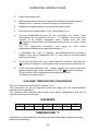
1
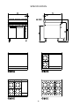
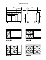
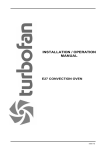
G50 / G50-8 GAS RANGE
MANUFACTURED BY
Moffat Limited
P O Box 10-001
Christchurch
New Zealand
Ph:
(03) 3891-007
Fax:
(03) 3891-276
WORLD-WIDE BRANCHES
UNITED KINGDOM
Blue Seal
Units 6-7, Mount Street Business Park
Mount Street, Nechells
Birmingham B7 5 QU
Ph:
(121) 327-5575
Fax:
(121) 327-9711
UNITED STATES
Moffat Inc
3765 Champion Blvd
Winston-Salem
North Carolina 27115
Ph:
(336) 661 0257
Fax:
(336) 661 9546
CANADA
Lessard Agencies Ltd
P O Box 97
Stn D Toronto
Ontario M6P3J5
Ph:
(416) 766-2764
Fax:
(416) 760-0394
NEW ZEALAND
Christchurch
Moffat Limited
P O Box 10-001
16 Osborne Street
Christchurch
Ph:
(03) 3891-007
Fax:
(03) 3891-276
Auckland
Moffat Limited
4 Waipuna Road
Mt Wellington
Auckland
Ph:
(09) 574-3150
Fax:
(09) 574-3159
AUSTRALIA
Victoria
Moffat Pty Limited
740 Springvale Road
Mulgrave, Melbourne
Victoria 3171
Ph:
(03) 9518-3888
Fax:
(03) 9518-3838
New South Wales
Moffat Pty Limited
8/142 James Ruse Drive, Rose Hill
P O Box 913, Smithfield
Sydney, N.S.W. 2142
Ph:
(02) 8833 4111
Fax:
(02) 8833 4133
Western Australia
Moffat Pty Limited
P O Box 689
Joondalup Business Centre
WA 6027
Ph:
(09) 305-8855
Fax:
(09) 308-8838
Queensland
Moffat Pty Limited
30 Prosperity Place
Geebung, Brisbane
Queensland 4034
Ph:
(07) 3215-9155
Fax
(07) 3215-9170
South Australia
Moffat Pty Limited
Unit 3/77 Prospect Road
Prospect, Adelaide
South Australia 5082
Ph:
(08) 8269-2633
Fax:
(08) 8269-2733
BLUE SEAL GAS RANGE
- G50 6 OPEN BURNER GAS RANGE
- G50-8 8 OPEN BURNER GAS RANGE
CONTENTS
PAGE
SPECIFICATION
1
INSTALLATION
6
OPERATING INSTRUCTIONS
9
CLEANING
11
MAINTENANCE
11
SERVICING INSTRUCTIONS
12
SPARE PARTS
17
Date Purchased .......................................................Serial No..................................................................
Dealer .......................................................................................................................................................
Service Agent............................................................................................................................................
F19455-13
SPECIFICATION
GENERAL
A heavy duty, general purpose gas range created for compact modular kitchens. It
has a high option hob/griddle arrangement.
The oven is provided with a piezo ignition lighted constant burning pilot, flame failure
device and temperature control thermostat.
The hob has Flame Failure Protection for each open burner.
MODEL NUMBERS OF RANGES INCLUDED IN THIS SPECIFICATION:
G50-D
G50-C
G50-B
G50-A
6 open burners plus oven
4 open burners plus 300mm griddle plus oven
2 open burners plus 600mm griddle plus oven
900mm griddle plus oven
G50-8D
G50-8C
G50-8B
G50-8A
8 open burners plus oven
6 open burners plus 300mm griddle plus oven
4 open burners plus 600mm griddle plus oven
2 open burners plus 900mm griddle plus oven
CATEGORY
Type:
Flue Type:A
I2H , I3P
HEAT INPUT (Based on GROSS Calorific Value)
Natural Gas (G20)
Propane Gas (G31)
Pressure
10 mbar
37 mbar
Open Burners
-Gas Rate
5.0 kW
0.48 m³/hr
5.0 kW
0.36 Kg/hr
Each 300 mm Griddle
-Gas Rate
5.5 kW
0.53 m³/hr
5.5 kW
0.40 Kg/hr
Oven
-Gas Rate
6.0 kW
0.57 m³/hr
5.5 kW
0.40 Kg/hr
Pilot
-Gas Rate
115 W
0.011 m³/hr
115 W
0.008 Kg/hr
-1-
SPECIFICATION
Model
Input
(G20)
G50-8D
G50-8C
G50-8B
G50-8A
46.0 kW
41.5 kW
37.0 kW
32.5 kW
G50D
G50C
G50B
G50A
36.0 kW
31.5 kW
27.0 kW
22.5 kW
Gas Rate
(G20)
Input
(G31)
Gas Rate
(G31)
4.41 m³/h
3.98 m³/h
3.55 m³/h
3.12 m³/h
45.5 kW
41.0 kW
36.5 kW
32.0 kW
3.25 kg/h
2.93 kg/h
2.60 kg/h
2.29 kg/h
3.45 m³/h
3.02 m³/h
2.59 m³/h
2.16 m³/h
35.5 kW
31.0 kW
26.5 kW
22.0 kW
2.54 kg/h
2.22 kg/h
1.89 kg/h
1.57 kg/h
GAS PRESSURE
Natural
(G20)
Propane (G31)
Supply Pressure
Burner Pressure
20 mbar (8.0” WG)
37 mbar (14.8: WG)
10 mbar (4.0" WG)
37 mbar ( 14.8" WG)
INJECTOR SIZES (mm)
Nat Gas (G20)
Prop Gas (G31)
Oven
2.80
1.50
Oven Pilot
0.32
0.23
Open Burners
1.90
1.10
Griddle Burners Griddle Pilot
2.10
0.32
1.20
0.20
OVERALL DIMENSIONS
Height to Hob
Height to Splashback
Width
Depth
G50
915mm
1065mm
900mm
812mm
G50-8
915 mm
1065 mm
1200 mm
812 mm
OVEN INTERNAL DIMENSIONS
Height
Width
Depth
G50
430mm
665mm
660mm
G50-8
430 mm
665 mm
660 mm
-2-
SPECIFICATION
WEIGHT (NETT)
Model G50D
Model G50-8D
220kg
295kg
GAS CONNECTION
Gas connection point 3/4" BSP male thread located 75mm from RH side,
55mm from rear and 610mm from floor.
-3-
SPECIFICATION
-4-
SPECIFICATION
-5-
INSTALLATION
It is important that this Range is installed correctly, and that the operation is correct
before handing over to the user.
THIS APPLIANCE MUST BE INSTALLED TO THE REQUIREMENTS OF THE
APPROVED LOCAL INSTALLATION CODE AND LOCAL AUTHORITY
REQUIREMENTS, COVERING GAS, FIRE AND HEALTH, AND IN ACCORDANCE
WITH THE NATIONAL INSTALLATION CODES:
THIS UNIT MUST BE INSTALLED BY A QUALIFIED INSTALLER.
- UNITED KINGDOM (GAS SAFETY/INSTALLATION & USE) REGULATIONS 1984
& 1990 AMENDMENT BS5440 PARTS 1 & 2 INSTALLATION FLUING &
VENTING
i)
DO NOT OBSTRUCT OR BLOCK THE APPLIANCES FLUE.
ii)
NEVER DIRECTLY CONNECT A VENTILATION SYSTEM TO THE APPLIANCE
FLUE OUTLET.
iii)
INSTALLATION MUST ALLOW FOR A SUFFICIENT FLOW OF FRESH AIR
FOR THE COMBUSTION AIR SUPPLY.
iv)
INSTALLATION MUST INCLUDE ADEQUATE VENTILATION MEANS, TO
PREVENT DANGEROUS BUILD UP OF COMBUSTION PRODUCTS.
A.
BEFORE ASSEMBLY AND CONNECTION
1.
Check the type of gas, the specified operating pressure and the oven's
hourly consumption. This information is clearly stated on the data plate
which is located next to oven control panel. (See Page 1).
2.
Check the gas supply and characteristics for the type of gas supply line
pressure and capacity.
3.
Installation must allow for a sufficient flow of fresh air for the combustion air
supply. Combustion air requirements:
G50
G50-8
Natural Gas (G20)
35m³/hr minimum
45m³/hr minimum
Propane Gas (G31)
33m³/hr minimum
42m³/hr minimum
4.
Components having adjustments protected (e.g. paint sealed) by
manufacturer are only allowed to be adjusted by an authorised service
agent. They are not to be adjusted by the installation person.
5.
The operating pressures for the respective gases are:
Propane Gas (G31)
Natural Gas (G20)
37 mbar (14.8" WG)
10 mbar (4.0" WG)
-6-
INSTALLATION
There are two pressure test points available for measurement of correct
appliance operating pressure. Either can be used and they are located;
i)
On the left hand end of the hob manifold, behind the hob control panel.
ii)
On the oven thermostatic gas control, behind the oven control panel.
Note that the two pressure test points are found on the oven
thermostatic gas control, of which the rear test point should be used in
this case.
One hob burner or griddle burner and the oven burner should be operating
at full rate when measuring the appliances operating pressure.
On PROPANE GAS the pressure is controlled by the supply pressure.
On NATURAL GAS the pressure is controlled by the appliances regulator,
which can be adjusted to obtain correct operating pressure.
B.
C.
6.
A regulator is supplied with appliances for use on NATURAL GAS. (These
should be fitted only by a Authorised person).
7.
After uncrating the range check all the dismantled parts (legs, etc.) and
"concealed" parts for transit damage. Report any damage to the carrier and
dealer as soon as possible.
ASSEMBLY
1.
Tilt the oven onto its LH side and fit both the front leg and rear roller in the
corresponding leg rings.
2.
Secure each one in place with the screw attached.
3.
Lift up the LH side of the oven, then fit and secure the front leg and rear
roller as described in (1) and (2).
4.
Check that all are in place and tightened firmly.
5.
Adjust the two front feet to make the oven steady and level.
GAS CONNECTION
1.
Gas supply connection is 3/4” BSP male. Refer to page 3 for connection
location details.
2.
The 3/4" gas regulator supplied only with ovens for use on NATURAL GAS
must be installed on the supply line for connection at the rear of the oven.
(See Page 3).
3.
Ovens for use on PROPANE do not have a regulator supplied, as the
pressure is controlled by a supply regulator at the PROPANE supply tank.
-7-
INSTALLATION
4.
It is important that adequately sized piping runs directly to the connection
joint on the oven, with as few tees and elbows as possible to give maximum
supply volume.
5.
An accessible shut-off valve must be fitted on the supply line before the
connection joint and pressure regulator.
6.
A suitable joining compound which resists the breakdown action of LPG
must be used on every gas line connection, unless compression fittings are
used.
7.
Check all connections for leakage. DO NOT USE A FLAME.
(NOTE: All connections to the gas supply must be by a Licensed Gas Fitter.)
D.
E.
LOCATION
1.
It is important to have a minimum of 25mm (1") of air space at the rear and
sides of the oven from combustibles surfaces.
2.
It is important to have a minimum of 1100 mm top clearance above the
cooking surface to a non-combustible ceiling or shelf and a minimum of
1500mm top clearance above the cooking surface to a combustible ceiling
of shelf.
COMMISSIONING
Before leaving the new installation, check Correct connections have been made,
and that the unit operates in accordance with the OPERATING INSTRUCTIONS
(Page 9).
NOTE: If for some reason it is not possible to get the appliance to function
correctly, then contact the supplier.
NOTE: Shut off the gas supply before any maintenance work is done on the
appliance. It is important to relight all pilot jets after changing gas
cylinders or reconnecting gas supply.
-8-
OPERATING INSTRUCTIONS
THIS APPLIANCE IS ONLY FOR PROFESSIONAL USE AND TO BE USED BY
QUALIFIED PEOPLE.
NOTE: Components having adjustments protected (e.g. paint sealed) by manufacturer
are only allowed to be adjusted by an authorised service agent. They are not to
be adjusted by the user.
If using aluminium foil in the base of the oven, ensure that it does not extend
past the oven base tray to ensure correct operation of the oven.
A.
B.
C.
HOB-OPEN TOP BURNERS
Flame Failure Protection is incorporated by way of a thermo-electric system for
each burner which will shut off the gas supply to that burner in the event that the
burner goes out, so that raw gas is not expelled.
1.
Select the burner, depress and turn the corresponding knob anti-clockwise
to position.
2.
With control knob depressed, light burner.
3.
Release knob after approximately 10-20 seconds after lighting burner.
4.
Burner should stay alight - if not, repeat Steps 2-3.
5.
The burner can now be operated. At this position it is FULL.
6.
To achieve simmer control, depress knob and rotate fully anti-clockwise. Or
operate between FULL and LOW positions.
7.
When main burner is not required, turn knob clockwise back to OFF
position.
GRIDDLES
1.
Depressed control knob and rotate anti-clockwise to PILOT
position.
2.
With the control knob depressed press Piezo button to ignite pilot burner.
Repeat until lit.
3.
Release knob approximately 10 seconds after lighting pilot.
4.
Pilot should now remain alight - if not, repeat Steps 2 to 4.
5.
Full flame can now be achieved by rotating control anti-clockwise to first
stop.
6.
Low flame can be achieved by depressing the control and rotating fully anticlockwise.
OVEN
1.
Open oven doors. Push in thermostat knob and rotate anti-clockwise to
PILOT position.
-9-
OPERATING INSTRUCTIONS
2.
Hold in thermostat knob.
3.
With the thermostat knob held in press Piezo button to ignite pilot burner.
Repeat until lit. View the lit burner through the inspection hole.
4.
Release knob approximately 10 seconds after lighting pilot.
5.
Pilot should now remain alight - if not, repeat Steps 2 to 4.
6.
The oven temperature can now be set by rotating the control knob
anticlockwise to any position from the 1 - 7 markings. The control knob
requires to be slightly depressed when starting from the pilot
position, however once out of the pilot position it can be freely turned
up or down.
See the
temperature conversion chart below for oven centre
temperatures obtained at the gas mark settings 1 - 7.
7.
If preheating the oven is required, set thermostat knob to position 4
(approx. oven centre temperature 200 °C) and allow 20 minutes before
cooking in the oven.
8.
To turn the oven off to pilot only, rotate the knob clockwise until the pilot
position is reached. In this position only the pilot burner will remain on.
9.
To turn the oven completely OFF, slightly depress the control knob from
the pilot position and rotate clockwise until OFF
position is reached.
The pilot burner will be shutdown and the gas valve closed.
To relight oven refer to step 1.
GAS MARK TEMPERATURE CONVERSIONS
The oven thermostat control knob is marked 1 to 7.
The thermostat can be set anywhere within this range and will thermostatically
maintain oven temperature.
The following chart indicates approximate oven centre temperatures that will be
maintained at the knob markings.
GAS MARK
1
100
2
130
3
160
4
190
5
225
6
260
7
290
TEMPERATURE °C
Temperatures required between the above should be obtained by setting the control
between the markings.
-10-
CLEANING & MAINTENANCE
CLEANING
THE GAS SUPPLY MUST BE OFF DURING CLEANING OR MAINTENANCE.
EXTERIOR
Clean with detergent. Baked on deposits or discolouration may require a good quality
stainless steel cleaner or stainless steel wool. Always apply cleaner when the range is
cool and rub in the direction of the "grain".
INTERIOR
Do not use wire brushes, steel wool or other abrasive materials. Clean the oven
regularly with a good quality domestic oven cleaner. Once a week, remove and clean
built up grease etc. from the oven racks and bottom spill over cover.
MAINTENANCE
To achieve the best results cleaning must be regular and thorough and all controls and
mechanical parts checked and adjusted periodically by a competent serviceman. If
any small faults occur, have them attended to promptly. Don't wait until they cause
complete breakdown. It is recommended that a service check is conducted every six
months.
-11-
SERVICING INSTRUCTIONS
NOTE:
Components having adjustments protected (e.g. paint sealed) by
manufacturer are only allowed to be adjusted by an authorised service
agent. They are not to be adjusted by an unauthorised service person.
OVEN
A.
BURNER AIR ADJUSTMENT
All gas adjustments should be done by a Qualified Person. The hob open top,
griddle and oven burners can all be adjusted to give the most efficient flame.
This is done by adjusting the aeration slides through which air is drawn in with the
injected gas.
The most efficient flame is clear blue/green in colour.
If the flame is yellow and wavey, then the burner needs adjusting.
B.
OVEN CONTROL
The thermostat valve used in this oven to control the oven burner and maintain
set temperature, also controls the oven pilot burner and flame failure protection.
The control has a combination modulating/snap action thermostat, allowing the
burner flame size to increase/decrease according to heat demand and to avoid
overshoot, and be shut off the burner when responding to rapid temperature
change requirements.
The thermostat is factory set and cannot be calibrated. However should the oven
temperature need checking, the following steps should be taken.
1.
Place an accurate thermometer or thermocouple in the centre of the oven.
2.
Ignite oven pilot as per operating instructions.
3.
Turn the thermostat knob to setting 4.
4.
Wait for the oven temperature to stabilise (approximately 20 minutes).
5.
Oven centre temperature should be 200 °C ± 10 °C.
Should a problem exist, the following checks should be made before assuming
the thermostatic control is faulty.
a.
b.
c.
d.
Check burner pressure.
Check MAXIMUM flow adjustment setting on control valve.
Check MINIMUM flow adjustment setting on control valve.
Pilot burner rate adjustment
Refer to page 13 for a, b, c & d procedures.
-12-
SERVICING INSTRUCTIONS
OVEN BURNER PRESSURE
To check oven burner pressure, fit a pressure gauge to the front pressure test
point on the oven thermostatic gas control located behind the oven control
panel.
The oven burner pressures should be measured with the oven burner operating:
a) At maximum flow setting (refer oven maximum flow setting).
b) At minimum flow setting (refer oven minimum flow setting).
To check correct appliance operating pressure and/or supply pressures refer to
installation section.
OVEN MAXIMUM FLOW SETTING
The maximum flow setting on the oven control is factory set on the oven control
is factory set and sealed.
It should not be necessary to adjust at any stage. However, if a control is being
replaced and correct operation is required to be verified, the following check
should be made;
With the pilot burner lit, the oven burner pressure should be as listed below
when measured with the burner operating at maximum rate.(Set control knob to
position 7).
NATURAL (G20) -8.7 mbar ± 1.0 (3.5” WG ±0.2”)
PROPANE (G31) -35 mbar ± 1.0 (14” WG ±0.4”)
The maximum flow rate adjuster screw is located on the underside of the control
and should always be two (2) turns out and sealed.
DO NOT unscrew more than two turns.
OVEN MINIMUM FLOW SETTING
The minimum flow setting is important to ensure good temperature control of the
oven.
The minimum flow setting on the oven control is factory set and sealed.
It should not be necessary to adjust at any stage. However, if a control is being
replaced and correct operation is required to be verified, the following check
should be made;
With the pilot burner lit set oven control knob to position 7.
Measure the oven burner pressure as described above, then turn the control
knob back until just before the thermostat control snap-action turns the burner
off. The burner should now be operating at the minimum flow rate. The burner
pressure at this rate should be as follows.
NATURAL (G20) -3.7 mbar ± 0.5 (1.5” WG ±0.2”)
PROPANE (G31) -7.5 mbar ± 1.0 (3.0” WG ±0.2”)
-13-
SERVICING INSTRUCTIONS
The minimum flow rate adjuster screw is located at the left hand bottom corner on
the front of the control. This screw should always be paint sealed.
PILOT FLAME SETTING
The pilot flame adjusting screw should always be fully open and is factory set and
sealed in this state.
Field adjustment should not be necessary unless replacing the control.
Correct setting is achieved by fully screwing in the adjustment screw, located at
the top right of the gas control front face, then unscrewing anticlockwise 3 full
turns.
Check the pilot flame operation and paint seal adjusting screw.
PIEZO IGNITION
To repair or replace, firstly check as described in "C" for Griddle, below.
C.
PILOT BURNERS AND PIEZO IGNITION FOR GRIDDLE AND
OVEN
PIEZO IGNITION
Should there be a fault with the piezo ignition system employed to ignite the
pilot burner, carry out the following:
1.
If spark is being generated but not sparking from ignition electrode to pilot
burner hood;
a.
b.
2.
Check H.T. lead and connections. Replace or repair.
Check ignition electrode is not cracked and is positively positioned.
Replace or repair.
If piezo igniter is faulty, remove from control panel and replace.
PILOT BURNER/THERMOCOUPLE
If pilot burner is not burning correctly check pilot orifice is not blocked and pilot is
clear. Clear and replace pilot orifice if necessary.
If pilot burner goes out check the following:
1.
Pilot burner is not blocked. Clean or replace pilot orifice.
2.
Thermocouple connection to gas control is firm. Tighten if necessary.
3.
Thermocouple is in working order. Should generate between 20-30mV.
Replace if faulty or suspect.
Electromagnet in rear of gas control is in good working order. Inspect and
replace if necessary.
4.
-14-
SERVICING INSTRUCTIONS
D.
GRIDDLE
MAIN BURNER
To replace unscrew 3/16" screw at rear of burner and remove. Refit new
burner.
GAS CONTROL - Servicing
To regrease gas control, remove control knobs and control panel. Remove 2
screws holding shaft plate to gas control body and remove control shaft and
plate. Note orientation of shaft for correct re-assembly.
Using needle nose pliers or similar, pull out gas control spool, again noting
orientation.
Using suitable compound rated for use with Natural and LP gases and high
temperature rating, re-grease spool.
Re-assemble by reversing procedure.
GAS CONTROL - Replacement
1.
Remove fat collection trays.
2.
Remove griddle plate.
3.
Remove knobs and control panel. Disconnect piezo H.T. lead from piezo
igniter.
4.
Remove securing nuts and washers from rear of each burner. Remove
burner(s).
5.
Unclip and remove front reflector plate from main griddle reflector panel.
6.
Slide reflector panel forward and lift away from rear.
7.
Undo pilot supply and disconnect pilot thermocouple from gas control.
8.
Using 19 mm spanner, undo compression nut securing gas control to
manifold assembly.
Re-assemble in reverse order and check for gas leaks with soapy water.
-15-
SERVICING INSTRUCTIONS
E.
OPEN BURNERS
GAS CONTROL - Servicing
To regrease gas control follow same procedure as in C for griddle gas
controls.
GAS CONTROL - Replacement
To replace gas control follow same procedure as in C for griddle gas
controls.
THERMOCOUPLE
Should the open burner not remain alight when the control knob is released after
ignition, it is likely that the thermo-electric flame failure system has a fault.
However, always remember to check burner operation and ignition procedures as
found in OPERATING SECTION are being correctly followed before servicing.
If a fault does exist, the following should be checked and rectified where
necessary.
1.
Inspect thermocouple for foreign build up on tip. This could be in the form of
carbon or food deposits.
Clean off any deposits taking care not to scratch off aluminium coating on
thermocouple tip.
2.
Remove enamelled pot-stand/trivet and check thermocouple
connection to gas control.
Connection nut should be hand tight, then a quarter turn with 10 mm
spanner.
3.
Check thermocouple tip is in the flame zone of the burner; ie when the
burner is lit, the flame should impinge on the top 5 mm of the thermocouple
tip.
The thermocouple should not touch the burner.
If the thermocouple is not correctly positioned, check the thermocouple
nut is secure in mounting bracket.
If the thermocouple is to low, loosen securing nut, push thermocouple
fully up into bush on mounting bracket and retighten securing nut.
4.
If 1-3 are correct, but burner will still not remain alight, disconnect
thermocouple and using a DC millivolts multimeter. Test thermocouple
for thermocouple for millivolts output with burner alight. Thermocouple
should produce 20-30 millivolts.
Replace thermocouple if faulty.
5.
If thermocouple produces the correct voltage, remove the aluminium
nut off the rear of the gas control and remove electro-magnet. Inspect
and test operation on thermocouple. Replace if necessary.
-16-
SPARE PARTS
RANGE G50, G50-8
Part No
HOB
Description
Open Burners
004573
004574
004618
037190
037110
019430
019428
019429
019371
Burner Front
Burner Rear
Burner Cap
Injector (NATURAL) Ø 1.90 mm
Injector (PROPANE) Ø 1.10 mm
Gas Control
Thermocouple - Front M9 x 320 mm UNIFIED
Thermocouple - Rear M9 x 850 mm UNIFIED
Pressure Test Point
Griddle
014105
034210
034130
017800
019215K
018692
018693
019428
016320
018095
016385
016386
016387
Burner
Injector (NATURAL) Ø 2.10mm
Injector (PROPANE) Ø 1.20mm
Gas Control
Pilot Burner
Pilot Orifice (PROPANE) Ø 0.20 mm
Pilot Orifice (NATURAL) Ø 0.32 mm
Thermocouple
Piezo Igniter
Piezo H.T Lead
Griddle 300mm
Griddle 600mm
Griddle 900mm
-17-
SPARE PARTS
RANGE G50, G50-8
Part No
Description
Oven
012248
018691K
020253
032280
032150
019217
018693
019406K
016320
018695
022407
022408
Oven Burner
Oven Pilot
Oven Thermocouple
Oven Burner Injector (NATURAL) Ø 2.80 mm
Oven Burner Injector (PROPANE) Ø 1.50 mm
Pilot Orifice (PROPANE) Ø 0.23 mm
Pilot Orifice (NATURAL) Ø 0.32 mm
Gas Control Thermostat Kit
Piezo Ignitor
Piezo H.T Lead
Low fire screw - (PROPANE) 0.95 mm
Low fire screw - (NATURAL) 1.5 mm
General
004125
016659
013634
004158
019435
019436
011853
004333
004334
013243
013244
011005
010254
018031
018081K
Pot Stand/Trivet
Pot Stand Spider
Hot Top (Cast Iron)
Hob Spillage Tray
Knob - Open Burner (FRONT & GRIDDLE)
Knob - Open Burner (REAR)
Regulator 3/4" - (Natural Gas only)
Door Inner Panel - Enamelled LH
Door Inner Panel - Enamelled RH
Door Outer Panel - RH
Door Outer Panel - LH
Ball Catch
Striker Plate
Handle Tube
Handle End Cap
-18-