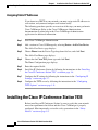
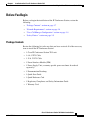
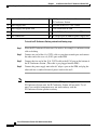
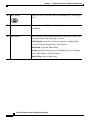
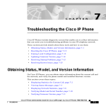
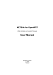
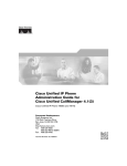
1
C H A P T E R
2
Installation of the Cisco IP Conference
Station 7935
For each IP Conference Station that you install in your network, you must first
make some critical decisions about how to configure the station in your
network.You can then safely install the IP Conference Station and verify its
operation.
Refer to the appropriate topics in this chapter to understand how to install and
configure the IP Conference Station.
•
Preparing to Install, page 2-1
•
Installing the Cisco IP Conference Station 7935, page 2-6
•
Introducing the Cisco IP Conference Station 7935, page 2-14
Preparing to Install
Before you begin installing the IP Conference Station, you must configure
Cisco CallManager for the conference stations and make decisions about how you
want the stations to be added to the Cisco CallManager database. Because
Cisco CallManager handles the call processing on the network, this is a critical
step. You can choose to have the stations auto-register themselves with the
database, or you can add the stations manually.
Cisco IP Conference Station 7935 Administration Guide
78-12727-03
2-1
Chapter 2
Installation of the Cisco IP Conference Station 7935
Preparing to Install
Setting the Default Device Load
To set the default device load for the IP Conference Station in
Cisco CallManager, perform these steps.
Step 1
Copy the IP Conference Station load to C:\Program Files\Cisco\TFTPPath on the
Cisco CallManager server.
Step 2
Start Cisco CallManager Administration.
Step 3
Choose System > Device Defaults.
Step 4
In the Device Defaults Configuration window, scroll down to the Cisco 7935
Device Type.
Step 5
Set the Load Information to the load in TFTPPath.
Step 6
Scroll back to the top of the page and click Update.
Adding a New Device
To add the IP Conference Station as a new device in Cisco CallManager, perform
these steps.
Step 1
Choose Device > Add a New Device.
The Add a New Device page displays.
Step 2
Choose Phone from the Device Type drop-down list box, and click Next.
The Add a New Phone page displays.
Step 3
Choose the the Cisco 7935 phone type and click Next. (Once you select a phone
type, you cannot modify it.)
The Phone Configuration page displays.
Step 4
Enter the required fields as described in the following table.
Cisco IP Conference Station 7935 Administration Guide
2-2
78-12727-03
Chapter 2
Installation of the Cisco IP Conference Station 7935
Preparing to Install
Field
Description
MAC Address
Enter the Media Access Control (MAC) address that
identifies Cisco IP Conference Station 7935. The value
must be 12 hexadecimal characters.
The MAC address is located on the bottom of the
IP Conference Station, or you may already have a list of
the MAC addresses of the IP Conference Stations you
are installing.
Device Pool
Choose the device pool to which you want this
IP Conference Station assigned. The device pool defines
sets of common characteristics for devices, such as
region, date/time group, Cisco CallManager group, and
calling search space for auto-registration.
The value you choose overrides the default value for this
type of device.
Phone Button
Template
Choose the appropriate phone button template. The
phone button template determines the configuration of
buttons on a phone and identifies which feature (line,
speed dial, and so on) is used for each button.
Step 5
At the top of the page, click Insert.
Step 6
Add a directory number to this IP Conference Station.
If you need instructions, refer to the “Directory Number Configuration Settings”
topic in the Cisco CallManager Administration online help.
Step 7
Reset the IP Conference Station to apply the new settings.
Using Auto-Registration
Use auto-registration to automatically add an IP Conference Station to the
network and automatically assign a directory number to it. During
auto-registration, the directory number assigned is the next one available in
sequential order within the device pool assigned to this conference station type in
Cisco CallManager.
Cisco IP Conference Station 7935 Administration Guide
78-12727-03
2-3
Chapter 2
Installation of the Cisco IP Conference Station 7935
Preparing to Install
If you enable auto-registration in Cisco CallManager, after you connect the
IP Conference Station to the network, the station begins the automatic startup
process to obtain a directory number.
You can also use auto-registration to quickly register all stations with the
Cisco CallManager database. You can then modify any settings, such as the
directory numbers, from Cisco CallManager.
The following procedure provides an overview of the steps you must perform in
Cisco CallManager. Refer to the Cisco CallManager Administration
documentation or online help in the Cisco CallManager Administration
application for additional information.
Step 1
Start Cisco CallManager Administration.
Step 2
Enable auto-registration in Cisco CallManager by selecting System >
Cisco CallManager.
Step 3
From the list of Cisco CallManagers, select the Cisco CallManager where you
want to check auto-registration.
Step 4
Verify that the “Auto-registration Disabled on this Cisco CallManager” setting is
not selected.
Step 5
Install the station by following the instructions in the “Installing the
Cisco IP Conference Station 7935” section on page 2-6.
Step 6
To modify settings, return to Cisco CallManager Adminisration and select Device
> Phone.
Enter search criteria for the new IP Conference Station and click Find. You
should see the MAC address for the new IP Conference Station.
Adding IP Conference Stations Manually
If you want to assign specific directory numbers to specific
IP Conference Stations without using auto-registration, you must manually add
each station to the Cisco CallManager database.
If you are not using Dynamic Host Configuration Protocol (DHCP) in your
network, you must also configure the IP settings and Trivial File Transfer Protocol
(TFTP) server locally on each station.
Cisco IP Conference Station 7935 Administration Guide
2-4
78-12727-03
Chapter 2
Installation of the Cisco IP Conference Station 7935
Preparing to Install
Alternatively, you might use DHCP, but want to manually set the TFTP server. In
this case, allow the station to start up, using DHCP, and then re-assign the TFTP
server.
Using DHCP
If you are using DHCP in your network, but you are not using auto-registration,
follow these steps to manually add the IP Conference Station to the
Cisco CallManager database.
The following procedure provides an overview of the steps you must perform in
Cisco CallManager. Refer to the Cisco CallManager Administration
documentation or online help in the Cisco CallManager Administration
application for additional information.
Step 1
Start Cisco CallManager Administration.
Step 2
Add an IP Conference Station to Cisco CallManager by selecting Device > Add
a New Device.
The Add a New Device page displays.
Step 3
Choose Phone from the Device Type drop-down list box, and click Next.
The Add a New Phone page displays.
Step 4
Choose the the Cisco 7935 phone type and click Next.
The Phone Configuration page displays.
Step 5
Enter the required fields.
Step 6
Install the station by following the instructions in the “Installing the
Cisco IP Conference Station 7935” section on page 2-6.
Cisco IP Conference Station 7935 Administration Guide
78-12727-03
2-5
Chapter 2
Installation of the Cisco IP Conference Station 7935
Installing the Cisco IP Conference Station 7935
Assigning Static IP Addresses
If you do not use DHCP in your network, you must assign static IP addresses to
each station, and you must configure each station locally.
The following procedure provides an overview of the steps you must perform in
Cisco CallManager. Refer to the Cisco CallManager Administration
documentation or online help in the Cisco CallManager Administration
application for additional information.
Step 1
Start Cisco CallManager Administration.
Step 2
Add a station to Cisco CallManager by selecting Device > Add a New Device.
The Add a New Device page displays.
Step 3
Choose Phone from the Device Type drop-down list box, and click Next.
The Add a New Phone page displays.
Step 4
Choose the the Cisco 7935 phone type and click Next.
The Phone Configuration page displays.
Step 5
Enter the required fields.
Step 6
Install the IP Conference Station by following the instructions in the “Installing
the Cisco IP Conference Station 7935” section on page 2-6.
Step 7
Configure the IP settings by following the instructions in the “Configuring IP
Settings” section on page 3-7.
Step 8
Configure the TFTP server by following the instructions in the “Configuring
TFTP Options” section on page 3-11.
Installing the Cisco IP Conference Station 7935
Before installing an IP Conference Station, be sure to verify that your network
meets the requirements that follow and that Cisco CallManager is properly
configured. Most importantly, review the safety precautions in the “Safety
Notices” section on page 2-9.
Cisco IP Conference Station 7935 Administration Guide
2-6
78-12727-03
Chapter 2
Installation of the Cisco IP Conference Station 7935
Installing the Cisco IP Conference Station 7935
Before You Begin
Before you begin the installation of the IP Conference Station, review the
following:
•
“Package Contents” section on page 2-7
•
“Network Requirements” section on page 2-8
•
“Cisco CallManager Configuration” section on page 2-8
•
“Safety Notices” section on page 2-9
Package Contents
Review the following list to be sure that you have received all of the necessary
iems to install the IP Conference Station.
•
1 Cisco IP Conference Station 7935 unit
•
1 6 ft. CAT 5 Cable
•
1 25 ft. CAT 5 Cable
•
1 Power Interface Module (PIM)
•
1 Power Supply Unit (a country-specific power cord must be ordered
separately)
•
1 Documentation Roadmap
•
1 Quick Start Guide
•
1 Quick Reference Card
•
1 Regulatory Compliance and Safety Information Guide
•
1 Warranty Card
Cisco IP Conference Station 7935 Administration Guide
78-12727-03
2-7
Chapter 2
Installation of the Cisco IP Conference Station 7935
Installing the Cisco IP Conference Station 7935
Network Requirements
For the IP Conference Station to successfully operate as an IP conference station
endpoint in your network, your network must meet the following requirements:
•
Working VoIP Network
– Voice over IP (VoIP) configured on your Cisco routers and gateways
– Cisco CallManager installed in your network and configured to handle
call processing
•
IP network that supports DHCP or manual assignment of IP address, gateway,
and subnet mask
•
TFTP Server
Cisco CallManager Configuration
The IP Conference Station requires Cisco CallManager to handle call processing.
Refer to the Cisco CallManager documentation or online help in the
Cisco CallManager Administration application to ensure that the
Cisco CallManager is properly set up to manage the IP Conference Station and to
properly route and process calls.
If you plan to use auto-registration, verify that it is enabled and properly
configured in Cisco CallManager before connecting any IP Conference Station to
the network. See the “Using Auto-Registration” section on page 2-3 for details.
Cisco IP Conference Station 7935 Administration Guide
2-8
78-12727-03
Chapter 2
Installation of the Cisco IP Conference Station 7935
Installing the Cisco IP Conference Station 7935
Safety Notices
These are the safety considerations for using the IP Conference Station. Read
these notices before you install or use the IP Conference Station. You can also
refer to the Regulatory Compliance and Safety Information for the Cisco IP
Conference Station 7935 for international agency compliance, safety, and
statutory information for the Cisco IP Conference Station 7935.
Warning
Read the installation instructions before you connect the system to its power
source.
Warning
Only trained and qualified personnel should be allowed to install, replace, or
service this equipment.
Warning
Ultimate disposal of this product should be handled according to all national
laws and regulations.
Warning
Do not work on the system or connect or disconnect cables during periods of
lightning activity.
Warning
To avoid electric shock, do not connect safety extra low voltage (SELV) circuits
to telephone network voltage (TNV) circuits. LAN ports contain SELV circuits,
and WAN ports contain TNV circuits. Some LAN and WAN ports both use RJ-45
connectors. Use caution when connecting cables.
Warning
This product relies on the building's installation for short-circuit (overcurrent)
protection. Ensure that a fuse or circuit breaker no larger than 120 VAC, 15 A U.S.
(240 VAC, 10 A international) is used on the phase conductors (all
current-carrying conductors).
Cisco IP Conference Station 7935 Administration Guide
78-12727-03
2-9
Chapter 2
Installation of the Cisco IP Conference Station 7935
Installing the Cisco IP Conference Station 7935
Warning
The device is designed to work with TN power systems.
Warning
The plug-socket combination must be accessible at all times because it serves
as the main disconnecting device.
Caution
The Cisco IP Conference Station 7935 is inoperable during a power outage if it is
not supported by a UPS (uninterruptible power supply) when using a local power
supply unit. This affects your ability to reach 911.
Caution
Using a cell phone or mobile phone in close proximity to an
IP Conference Station might cause interference.
Cisco IP Conference Station 7935 Administration Guide
2-10
78-12727-03
Chapter 2
Installation of the Cisco IP Conference Station 7935
Installing the Cisco IP Conference Station 7935
Installing and Connecting to the Network
You must connect the IP Conference Station to the network and to a power source
before using it. Refer to the following picture for graphical views of the
installation procedures.
Note
Daisy-chaining IP Conference Stations to other Cisco IP Phones is not supported
and will not work.\
4
Cisco IP Conference Station 7935 Administration Guide
78-12727-03
2-11
Chapter 2
Installation of the Cisco IP Conference Station 7935
Installing the Cisco IP Conference Station 7935
1
Power outlet in the wall
6
RJ-45 port on the bottom of the
IP Conference Station
2
Power supply unit
7
Free end of the 25 ft. CAT 5 cable
3
Power supply unit power cord
8
LAN connection on PIM
4
PIM
9
25 ft. CAT 5 cable connection on PIM
5
LAN connection
10 AC adapter port on PIM for power supply unit
To install an IP Conference Station, perform the following steps:
Step 1
Place the IP Conference Station on a flat surface, for example, a conference room
table or desktop.
Step 2
Connect one end of the 6 ft. CAT 5 cable to your data network port and connect
the other end to the network (LAN) port on the PIM.
Step 3
Connect the free end of the 25 ft. CAT 5 cable to the RJ-45 port on the bottom of
the IP Conference Station. (The cable is pre-plugged into the PIM.)
Step 4
Connect the power supply unit to the AC adapter port on the PIM, and plug the
other end into a standard electrical power outlet in the wall.
Note
If you do not correctly connect the cables, PIM, power supply, and the
IP Conference Station unit, the IP Conference Station will not work. Use of
non-Cisco certified components may not work and may void the
IP Conference Station product warranty.
Cisco IP Conference Station 7935 Administration Guide
2-12
78-12727-03
Chapter 2
Installation of the Cisco IP Conference Station 7935
Installing the Cisco IP Conference Station 7935
Verifying Startup Process
After the IP Conference Station has been connected to power for at least 15
seconds, it begins its startup process by cycling through these steps:
1.
The following messages appear in the LCD screen display as the
IP Conference Station starts up:
– Cisco Systems, Inc.
Polycom Technology
Copyright 2001
– Renewing/Obtaining IP Address
Loading Application
Configuring IP
Press Menu to Reconfigure
– Station IP (IP address)
Contacting (IP address)
– Opening: CM IP address
– Registering
Note
2.
The startup process may take several minutes, and some of these
messages may not appear due to the access speed of your network.
After the IP Conference Station has successfully registered with a
Cisco CallManager, the following information appears in the LCD screen
display:
– Date and Time
– IP Address
– Local number
– The message “Press the Phone Key to get a dial tone”
– Corp Dir and Ph Book softkeys
If the IP Conference Station successfully passes through these steps, it has started
properly.
Cisco IP Conference Station 7935 Administration Guide
78-12727-03
2-13
Chapter 2
Installation of the Cisco IP Conference Station 7935
Introducing the Cisco IP Conference Station 7935
Configuring Startup Network Settings
If you are not using DHCP in your network, you must configure the following
network settings on the IP Conference Station after installing the station on the
network:
•
IP address
•
IP subnet mask
•
Default gateway IP address
•
TFTP server IP address
Collect the necessary information and follow the procedures described in
Chapter 3, “Configuration of the Cisco IP Conference Station 7935”.
Introducing the Cisco IP Conference Station 7935
The IP Conference Station provides basic business audio conferencing features
and functions, such as Call Hold, Call Transfer, Call Release, Mute, and
Conference, over an IP network. It is designed to be used primarily on desktops
and in small- to medium-sized conference rooms to facilitate conference calling.
It replaces a traditional analog conferencing unit on an IP telephony network. The
IP Conference Station supports G.711 and G.729a audio compression.
The IP Conference Station is shown in the following picture.
Cisco IP Conference Station 7935 Administration Guide
2-14
78-12727-03
Chapter 2
Installation of the Cisco IP Conference Station 7935
Introducing the Cisco IP Conference Station 7935
Cisco IP Conference Station 7935 Administration Guide
78-12727-03
2-15
Chapter 2
Installation of the Cisco IP Conference Station 7935
Introducing the Cisco IP Conference Station 7935
1
LEDs
Provide call status indicators.
Call State Off: LEDs All off
Dial Tone On: LEDs All Green
Dialing: LEDs All Green
Connected: LEDs All Green
Mute: LEDs All Red and blinking
Hold: LEDs All Red and on
Incoming Call: LEDs All Green and blink with ring
Ringing: LEDs All Green and blink with ring
2
LCD screen
Provides a status indicator that reads “Press the Phone Key to get a
dial tone” when the IP Conference Station is online and fully
operational. In the main display, the LCD screen shows the date and
time, IP address, and local phone number assigned to the
IP Conference Station. Also displays the IP Conference Station
system status, including configuration and all administrative
settings.
3
Scroll buttons
Allow you to scroll through the menus or through an open list in the
LCD screen.
4
Select button
Selects a menu option or list item that is highlighted.
Cisco IP Conference Station 7935 Administration Guide
2-16
78-12727-03
Chapter 2
Installation of the Cisco IP Conference Station 7935
Introducing the Cisco IP Conference Station 7935
5
Softkeys
Answer: picks up the current call
Conf: adds a party to a conference call
Corp Dir: lets you search a corporate directory for a number to call
End Call: ends a call and returns to the resting display or to the
active call list
Hold: puts the active call on hold
GPickup: lets you pick up a call within your group or another group
Pickup: lets you pick up a call within your group
Ph Book: opens the Phone Book
New Call: lets you dial a new number
Resume: returns to the selected held call
Transfer: transfers the current call
6
Volume buttons
Increase or decrease the volume of the call, speaker, ringer, or dial
tone, depending on which sound is currently active.
7
Mute button
Turns call muting on or off.
8
Dialing pad
Allows you to dial phone numbers, add or edit Phone Book entries,
and enter other input depending on the menu selected.
9
Redial button
Automatically redials the last dialed number.
Cisco IP Conference Station 7935 Administration Guide
78-12727-03
2-17
Chapter 2
Installation of the Cisco IP Conference Station 7935
Introducing the Cisco IP Conference Station 7935
10 Phone button
Allows you to get a dial tone, answer an incoming call, and hang up
a call.
11 Exit button
Returns to the main LCD screen display from a menu, a list, or the
Phone Book.
12 Menu button
Opens and closes the main menu on the IP Conference Station. The
main menu includes the following selections:
Call Functions: opens the call function options, including Meet
Me, Park, Pick-up, Group Pick-up, and Transfer.
Phone Book: opens the Phone Book.
Settings: opens the Settings options, including Contrast, Language,
Ringer, Time Format, and Date Format.
Admin Setup: opens Admin Setup.
Cisco IP Conference Station 7935 Administration Guide
2-18
78-12727-03