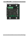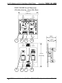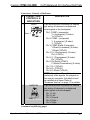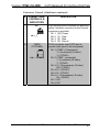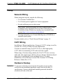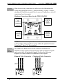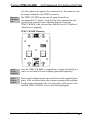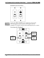
1
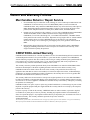
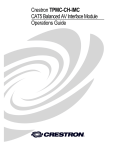
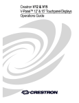
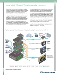
Crestron TPMC-CH-IMW
CAT5 Balanced AV Interface Wall Plate
Operations Guide
This document was prepared and written by the Technical Documentation department at:
Crestron Electronics, Inc.
15 Volvo Drive
Rockleigh, NJ 07647
1-888-CRESTRON
All brand names, product names and trademarks are the property of their respective owners.
©2006 Crestron Electronics, Inc.
Crestron TPMC-CH-IMW
CAT5 Balanced AV Interface Wall Plate
Contents
CAT5 Balanced AV Interface Wall Plate: TPMC-CH-IMW
1
Introduction......................................................................................1
Features & Functions.............................................................1
Specifications.........................................................................2
Physical Description ..............................................................4
Industry Compliance............................................................10
Setup...............................................................................................11
Network Wiring ...................................................................11
CAT5 Wiring .......................................................................11
Hardware Hookup................................................................11
Problem Solving.............................................................................15
Troubleshooting...................................................................15
Check Network Wiring........................................................15
Reference Documents..........................................................17
Further Inquiries ..................................................................17
Future Updates.....................................................................17
Return and Warranty Policies ........................................................18
Merchandise Returns / Repair Service ................................18
CRESTRON Limited Warranty ..........................................18
Operations Guide - DOC. 6448
Contents • i
Crestron TPMC-CH-IMW
CAT5 Balanced AV Interface Wall Plate
CAT5 Balanced AV Interface Wall
Plate: TPMC-CH-IMW
Introduction
Features & Functions
• CAT5 Balanced AV Interface Wall Plate for Isys® TPS and
TPMC-CH touchpanels*
• Mounts in a 2-gang electrical box
• Uses CresCAT™-D cable to carry Cresnet®, bidirectional
audio, and video signals up to 500 feet
• Carries 24 Volts DC power to touchpanels that require power
from the NET connector
• Supports composite, S-video, and component video
• Connects to conventional audio and coaxial video sources
*
The TPMC-CH-IMW is not compatible with QuickMedia™ touchpanels or
touchpanels with a 10-pin RJ-45 NET/VIDEO connector.
Operations Guide – DOC. 6448
CAT5 Balanced AV Interface Wall Plate: TPMC-CH-IMW • 1
CAT5 Balanced AV Interface Wall Plate
Crestron TPMC-CH-IMW
Specifications
Specifications for the TPMC-CH-IMW are listed in the following table.
TPMC-CH-IMW Specifications
SPECIFICATION
Front Panel
AUDIO
Output Impedance
Maximum Output Level
Input Impedance
VIDEO
Output Impedance
Rear Panel
VIDEO
Input Impedance
Input Level
Maximum DC Offset
AUDIO IN
Input Impedance
Maximum Input Level
AUDIO OUT
DETAILS
RJ-45 female, CAT5 balanced audio
input/output port
100 ohms balanced
2 VRMS
Infinite (unbuffered pass-thru to rear
AUDIO OUT port)
RJ-45 female, CAT5 balanced video
output port carries composite, S-video,
and component signals to touchpanel
100 ohms balanced
9-pin terminal block connector for
video input to touchpanel.
100 ohms balanced
(also accepts 75 ohm unbalanced)
1 Vp-p nominal, 1.5 Vp-p maximum
1.5 Volts
5-pin terminal block connector.
Balanced/unbalanced stereo line-level
input to touchpanel.
20k ohm balanced,
10k ohm unbalanced
4 VRMS balanced,
2 VRMS unbalanced
5-pin terminal block connector.
Balanced stereo line-level output from
touchpanel (unbuffered pass-thru from
front AUDIO port).
(continued on following page)
2 • CAT5 Balanced AV Interface Wall Plate: TPMC-CH-IMW
Operations Guide – DOC. 6448
Crestron TPMC-CH-IMW
CAT5 Balanced AV Interface Wall Plate
TPMC-CH-IMW Specifications (continued)
SPECIFICATION
Power Requirements
Cresnet Power Usage
Environmental
Temperature
Humidity
Enclosure
Dimensions
Height
Width
Depth
Weight
Operations Guide – DOC. 6448
DETAILS
2 Watts (0.08 Amps @ 24 Volts DC)
41° to 122°F (5° to 50°C)
10% to 90% RH (non-condensing)
2-gang mountable in a standard
electrical box (2.5 inch deep
minimum). Includes black metal front
panel Decora® inserts; requires
Decora faceplate (provided by others).
4.11 in (10.44 cm)
3.50 in (8.89 cm)
1.66 in (4.22 cm)
7.5 oz (0.21 kg)
CAT5 Balanced AV Interface Wall Plate: TPMC-CH-IMW • 3
CAT5 Balanced AV Interface Wall Plate
Crestron TPMC-CH-IMW
Physical Description
This section provides information on the connections and indicators
available on your TPMC-CH-IMW.
Physical View of the TPMC-CH-IMW, Front
4 • CAT5 Balanced AV Interface Wall Plate: TPMC-CH-IMW
Operations Guide – DOC. 6448
Crestron TPMC-CH-IMW
CAT5 Balanced AV Interface Wall Plate
Physical View of the TPMC-CH-IMW, Rear
Operations Guide – DOC. 6448
CAT5 Balanced AV Interface Wall Plate: TPMC-CH-IMW • 5
CAT5 Balanced AV Interface Wall Plate
Crestron TPMC-CH-IMW
TPMC-CH-IMW Overall Dimensions
(Clockwise from top – Front, Side, Rear)
3.50 in
(8.89 cm)
1
2
3
1.66 in
(4.22 cm)
1.49 in
(3.78 cm)
4
4.11 in
(10.44 cm)
5
6
7
8
6 • CAT5 Balanced AV Interface Wall Plate: TPMC-CH-IMW
Operations Guide – DOC. 6448
Crestron TPMC-CH-IMW
CAT5 Balanced AV Interface Wall Plate
Connectors, Controls, & Indicators
#
CONNECTORS,
CONTROLS, &
INDICATORS
DESCRIPTION
1
VIDEO
9-pin terminal block connector for twisted
pair wiring of balanced or unbalanced
video signals to the touchpanel.
Pin1: COMP+ (composite)
Y+ (Luminance) (S-video)
Y+ (Y/Pb/Pr)
Pin 2: COMP - (composite)
Y- (Luminance) (S-video)
Y- (Y/Pb/Pr)
Pin 3: COMP Shield (Composite)
Y Shield (Luminance) (S-video)
Y Shield (Y/Pb/Pr)
Pin 4: C+ (Chrominance) (S-video)
Pb+ (Y/Pb/Pr)
Pin 5: C- (Chrominance) (S-video)
Pb- (Y/Pb/Pr)
Pin 6: Pb Shield (Y/Pb/Pr)
C Shield (Chrominance) (S-video)
Pin 7: Pr+ (Y/Pb/Pr)
Pin 8: Pr- (Y/Pb/Pr)
Pin 9: Pr Shield (Y/Pb/Pr)
PIN 1
NOTE: Except for differential input
(balanced) video signals, the jumpers on
the nine-pin connector (included) should
be installed at all times. Refer to
“Hardware Hookup” on page 11 for details.
2
AUDIO IN
PIN 1
5-pin terminal block connector for twisted
pair wiring of balanced or unbalanced
audio signals to the touchpanel.
Pin 1: Left +
Pin 2: Left Pin 3: Ground
Pin 4: Right +
Pin 5: Right -
(continued on following page)
Operations Guide – DOC. 6448
CAT5 Balanced AV Interface Wall Plate: TPMC-CH-IMW • 7
CAT5 Balanced AV Interface Wall Plate
Crestron TPMC-CH-IMW
Connectors, Controls, & Indicators (continued)
#
CONNECTORS,
CONTROLS, &
INDICATORS
DESCRIPTION
3
NET
4-pin terminal block connector for data and
power. Interface connector for the Cresnet
connector is provided.
Pin 1: (24) Power
Pin 2: (Y) Data
Pin 3: (Z) Data
Pin 4: (G) Ground
5-pin terminal block connector for twisted
pair wiring of balanced or unbalanced
audio signals from the touchpanel.
Pin 1: Left +
Pin 2: Left Pin 3: Ground
Pin 4: Right +
Pin 5: Right Indicates 24 Volts DC power supplied from
Cresnet control network.
RJ-45 connector uses CAT5 wire to
provide audio input to the touchpanel and
microphone output from the touchpanel.
Pin 1: Mic Output Left (+)
Pin 2: Mic Output Left (-)
Pin 3: Mic Output Right (+)
Pin 4: Audio Input Left (+)
Pin 5: Audio Input Left (-)
Pin 6: Mic Output Right (-)
Pin 7: Audio Input Right (+)
Pin 8: Audio Input Right (-)
PIN 1
4
AUDIO OUT
PIN 1
5
PWR LED
6
AUDIO
PIN 1
(continued on following page)
8 • CAT5 Balanced AV Interface Wall Plate: TPMC-CH-IMW
Operations Guide – DOC. 6448
Crestron TPMC-CH-IMW
CAT5 Balanced AV Interface Wall Plate
Connectors, Controls, & Indicators (continued)
#
CONNECTORS,
CONTROLS, &
INDICATORS
DESCRIPTION
7
NET
4-pin terminal block connector for data and
power. Interface connector for the Cresnet
connector is provided.
Pin 1: (24) Power
Pin 2: (Y) Data
Pin 3: (Z) Data
Pin 4: (G) Ground
RJ-45 connector uses CAT5 wire to
provide video input to the touchpanel.
Pin 1: COMP + (Component)
Y+ (Luminance) (S-video)
Y+ (Y/Pb/Pr)
Pin 2: COMP - (composite)
Y- (Luminance) (S-video)
Y- (Y/Pb/Pr)
Pin 3: C+ (Chrominance) (S-video)
Pb+ (Y/Pb/Pr)
Pin 4: Pr+ (Y/Pb/Pr)
Pin 5: Pr- (Y/Pb/Pr)
Pin 6: C- (Chrominance) (S-video)
Pb- (Y/Pb/Pr)
Pin 7: N/C
Pin 8: N/C
PIN 1
8
VIDEO
(TO PANEL)
PIN 1
Operations Guide – DOC. 6448
CAT5 Balanced AV Interface Wall Plate: TPMC-CH-IMW • 9
CAT5 Balanced AV Interface Wall Plate
Crestron TPMC-CH-IMW
Industry Compliance
As of the date of manufacture, the TPMC-CH-IMW has been tested and
found to comply with specifications for CE marking and standards per
EMC and Radiocommunications Compliance Labelling.
NOTE: This device complies with part 15 of the FCC rules. Operation is
subject to the following two conditions: (1) this device may not cause
harmful interference, and (2) this device must accept any interference
received, including interference that may cause undesired operation.
This equipment has been tested and found to comply with the limits for a
Class B digital device, pursuant to part 15 of the FCC Rules. These limits
are designed to provide reasonable protection against harmful
interference in a residential installation. This equipment generates, uses
and can radiate radio frequency energy and, if not installed and used in
accordance with the instructions, may cause harmful interference to radio
communications. However, there is no guarantee that interference will
not occur in a particular installation. If this equipment does cause harmful
interference to radio or television reception, which can be determined by
turning the equipment off and on, the user is encouraged to try to correct
the interference by one or more of the following measures:
Reorient or relocate the receiving antenna.
Increase the separation between the equipment and receiver.
Connect the equipment into an outlet on a circuit different from that to
which the receiver is connected.
Consult the dealer or an experienced radio/TV technician for help.
10 • CAT5 Balanced AV Interface Wall Plate: TPMC-CH-IMW Operations Guide – DOC. 6448
Crestron TPMC-CH-IMW
CAT5 Balanced AV Interface Wall Plate
Setup
Network Wiring
When wiring the network, consider the following:
•
Use Crestron Certified Wire.
•
Use Crestron power supplies for Crestron equipment.
•
Provide sufficient power to the system.
CAUTION: Insufficient power can lead to unpredictable results
or damage to the equipment. Please use the Crestron Power
Calculator to help calculate how much power is needed for the
system (http://www.crestron.com/calculators).
•
For larger networks, use a Cresnet Hub/Repeater (CNXHUB) to
maintain signal quality.
For more details, refer to “Check Network Wiring” on page 15.
CAT5 Wiring
In addition to Ethernet applications, Category 5 (CAT5) wiring is used by
Crestron for a variety of audio and video applications.
Crestron recommends using CresCAT-D wire or other high-quality
CAT5 cable for transmitting CAT5 audio and video signals.
When using a Crestron wiring solution, the CresCAT-D wire can carry
audio and video signals up to 500 feet (observe distance limitations based
upon power consumption for the touchpanel in use). For more
information, refer to the latest version of the Crestron CAT5 Wiring
Reference Guide (Doc. 6137).
Hardware Hookup
Ventilation
To prevent overheating, do not operate this product in an area that
exceeds the environmental temperature range listed in the table of
specifications. Contact with thermal insulating materials should be
avoided on all sides of the unit.
Operations Guide – DOC. 6448 CAT5 Balanced AV Interface Wall Plate: TPMC-CH-IMW • 11
CAT5 Balanced AV Interface Wall Plate
Connect
the Device
Crestron TPMC-CH-IMW
Make the necessary connections as called out in the illustration that
follows this paragraph. Refer to “Network Wiring” on page 11 before
attaching the 4-position terminal block connector. Apply power after all
connections have been made.
Hardware Connections (Rear) for the TPMC-CH-IMW
VIDEO:
BALANCED
OR
UNBALANCED
YPbPr,
S-VIDEO, OR
COMPOSITE
SOURCES
CRESNET:
TO CONTROL
SYSTEM AND
OTHER
CRESNET
DEVICES
AUDIO IN:
LINE-LEVEL,
BALANCED &
UNBALANCED
AUDIO
SOURCES
AUDIO OUT:
PROVIDES
LINE-LEVEL
BALANCED
OUTPUT
NOTE: It is not necessary to make connections to a video source unless
a video window object resides on a page within the uploaded Crestron
VisionTools® Pro-e (VT Pro-e) project.
Connect
Video
Sources
The TPMC-CH-IMW allows for the connection of balanced or
unbalanced video signals using twisted pair cable for balanced signals
and coaxial cable for unbalanced signals. Refer to the following
diagrams to connect balanced or unbalanced video signals.
Balanced Video Connection
JUMPERS
REMOVED
Unbalanced Video Connection
JUMPERS
REMAIN IN
PLACE
12 • CAT5 Balanced AV Interface Wall Plate: TPMC-CH-IMW Operations Guide – DOC. 6448
Crestron TPMC-CH-IMW
CAT5 Balanced AV Interface Wall Plate
If a video signal is not going to be connected, leave the connector with
the jumpers attached to the VIDEO connector.
Mount in
Electrical
Box
The TPMC-CH-IMW mounts into a 2-gang electrical box
(recommended 2.5" depth). Verify that the unit is mounted into the
electrical box as shown in the following diagram. Secure the
TPMC-CH-IMW to the electrical box with the four #6-32 flat-head
slotted screws (supplied).
TPMC-CH-IMW Mounting
Install
Decora
Wallplate
Once the TPMC-CH-IMW is mounted into a 2-gang electrical box, it
can be covered with a Decora wallplate (purchased separately).
Install
Decora
Inserts
Remove the backing from the tape on the back of the supplied insert
plates. Affix each insert plate into its proper opening in the wallplate.
For the proper orientation of the two insert plates with respect to the
installed TPMC-CH-IMW, refer to the following diagram.
Operations Guide – DOC. 6448 CAT5 Balanced AV Interface Wall Plate: TPMC-CH-IMW • 13
CAT5 Balanced AV Interface Wall Plate
Crestron TPMC-CH-IMW
Orientation of the Insert Plates
Connect to Connect the TPMC-CH-IMW to the touchpanel as shown in the
the
following diagram using the triamese cable supplied with the
Touchpanel
touchpanel. The triamese cable has labels indicating the port to connect.
Connecting to the Touchpanel
NET:
CONNECT TO
NET PORT ON
TOUCHPANEL
AUDIO:
CONNECT TO
AUDIO PORT
ON
TOUCHPANEL
VIDEO:
CONNECT TO
VIDEO PORT
ON
TOUCHPANEL
14 • CAT5 Balanced AV Interface Wall Plate: TPMC-CH-IMW Operations Guide – DOC. 6448
Crestron TPMC-CH-IMW
CAT5 Balanced AV Interface Wall Plate
Problem Solving
Troubleshooting
The following table provides corrective action for possible trouble
situations. If further assistance is required, please contact a Crestron
customer service representative.
TPMC-CH-IMW Troubleshooting
TROUBLE
POSSIBLE
CAUSE(S)
CORRECTIVE ACTION
Touchpanel
does not
function.
Touchpanel is not
receiving power.
Touchpanel is not
communicating to the
network.
Improper video
connection.
Confirm that power is supplied
via the Cresnet connector.
Use Crestron Toolbox to poll
the network. Verify network
connection to the touchpanel.
Verify connections on the
touchpanel and
TPMC-CH-IMW.
Select the proper video input
configuration in the touchpanel
configuration SETUP MENU.
Video
window on
touchpanel
has no
display.
Incorrect video
format selection.
Incorrect VT Pro-e
project file loaded.
Make sure that video window
object resides in project, recompile, and reload.
Damaged connector
pins.
Inspect connector pins. If bent,
carefully re-straighten. If
broken, contact Crestron
customer service.
Check Network Wiring
Use the
Right Wire
In order to ensure optimum performance over the full range of your
installation topology, Crestron Certified Wire, and only Crestron
Certified Wire, may be used. Failure to do so may incur additional
charges if support is required to identify performance deficiencies as a
result of using improper wire.
Operations Guide – DOC. 6448 CAT5 Balanced AV Interface Wall Plate: TPMC-CH-IMW • 15
CAT5 Balanced AV Interface Wall Plate
Calculate
Power
Crestron TPMC-CH-IMW
CAUTION: Use only Crestron power supplies for Crestron equipment.
Failure to do so could cause equipment damage or void the Crestron
warranty.
CAUTION: Provide sufficient power to the system. Insufficient power
can lead to unpredictable results or damage to the equipment. Please use
the Crestron Power Calculator to help calculate how much power is
needed for the system (http://www.crestron.com/calculators).
When calculating the length of wire for a particular Cresnet run, the wire
gauge and the Cresnet power usage of each network unit to be connected
must be taken into consideration. Use Crestron Certified Wire only. If
Cresnet units are to be daisy-chained on the run, the Cresnet power usage
of each network unit to be daisy-chained must be added together to
determine the Cresnet power usage of the entire chain. If the unit is a
home-run from a Crestron system power supply network port, the
Cresnet power usage of that unit is the Cresnet power usage of the entire
run. The wire gauge and the Cresnet power usage of the run should be
used in the following equation to calculate the cable length value on the
equation’s left side.
Cable Length Equation
L<
40,000
RxP
Where: L = Length of run (or chain) in feet.
2
R = 6 Ohms (Crestron Certified Wire: 18 AWG (0.75 MM ))
P = Cresnet power usage of entire run (or chain).
Make sure the cable length value is less than the value calculated on the
right side of the equation. For example, a Cresnet run drawing 20 watts
should not have a length of run more than 333 feet.
NOTE: All Crestron certified Cresnet wiring must consist of two
twisted pairs. One twisted pair is the +24V conductor and the GND
conductor, and the other twisted pair is the Y conductor and the Z
conductor.
Strip and
Tin Wire
When daisy-chaining Cresnet units, strip the ends of the wires carefully
to avoid nicking the conductors. Twist together the ends of the wires that
share a pin on the network connector, and tin the twisted connection.
Apply solder only to the ends of the twisted wires. Avoid tinning too far
up the wires or the end becomes brittle. Insert the tinned connection into
the Cresnet connector and tighten the retaining screw. Repeat the
procedure for the other three conductors.
16 • CAT5 Balanced AV Interface Wall Plate: TPMC-CH-IMW Operations Guide – DOC. 6448
Crestron TPMC-CH-IMW
Add Hubs
CAT5 Balanced AV Interface Wall Plate
For larger networks (i.e., greater than 28 network devices), it may
become necessary to add a Cresnet Hub/Repeater (CNXHUB) to
maintain signal quality throughout the network. Also, for networks with
lengthy cable runs, it may be necessary to add a Hub/Repeater after only
20 devices.
Reference Documents
The latest version of all documents mentioned within the guide can be
obtained from the Crestron website (http://www.crestron.com/manuals).
This link will provide a list of product manuals arranged in alphabetical
order by model number.
List of Related Reference Documents
DOCUMENT TITLE
CAT5 Wiring Reference Guide
Further Inquiries
If you cannot locate specific information or have questions after
reviewing this guide, please take advantage of Crestron's award winning
customer service team by calling the Crestron corporate headquarters at
1-888-CRESTRON [1-888-273-7876]. For assistance in your local time
zone, refer to the Crestron website (http://www.crestron.com/) for a
listing of Crestron worldwide offices.
You can also log onto the online help section of the Crestron website to
ask questions about Crestron products. First-time users will need to
establish a user account to fully benefit from all available features.
Future Updates
As Crestron improves functions, adds new features, and extends the
capabilities of the TPMC-CH-IMW, additional information may be made
available as manual updates. These updates are solely electronic and
serve as intermediary supplements prior to the release of a complete
technical documentation revision.
Check the Crestron website periodically for manual update availability
and its relevance. Updates are identified as an “Addendum” in the
Download column.
Operations Guide – DOC. 6448 CAT5 Balanced AV Interface Wall Plate: TPMC-CH-IMW • 17
CAT5 Balanced AV Interface Wall Plate
Crestron TPMC-CH-IMW
Return and Warranty Policies
Merchandise Returns / Repair Service
1.
No merchandise may be returned for credit, exchange, or service without prior authorization from
CRESTRON. To obtain warranty service for CRESTRON products, contact an authorized
CRESTRON dealer. Only authorized CRESTRON dealers may contact the factory and request an
RMA (Return Merchandise Authorization) number. Enclose a note specifying the nature of the
problem, name and phone number of contact person, RMA number, and return address.
2.
Products may be returned for credit, exchange, or service with a CRESTRON Return Merchandise
Authorization (RMA) number. Authorized returns must be shipped freight prepaid to
CRESTRON, 6 Volvo Drive, Rockleigh, N.J., or its authorized subsidiaries, with RMA number
clearly marked on the outside of all cartons. Shipments arriving freight collect or without an RMA
number shall be subject to refusal. CRESTRON reserves the right in its sole and absolute
discretion to charge a 15% restocking fee, plus shipping costs, on any products returned with an
RMA.
3.
Return freight charges following repair of items under warranty shall be paid by CRESTRON,
shipping by standard ground carrier. In the event repairs are found to be non-warranty, return
freight costs shall be paid by the purchaser.
CRESTRON Limited Warranty
CRESTRON ELECTRONICS, Inc. warrants its products to be free from manufacturing defects in materials and
workmanship under normal use for a period of three (3) years from the date of purchase from CRESTRON,
with the following exceptions: disk drives and any other moving or rotating mechanical parts, pan/tilt heads and
power supplies are covered for a period of one (1) year; touchscreen display and overlay components are
covered for 90 days; batteries and incandescent lamps are not covered.
This warranty extends to products purchased directly from CRESTRON or an authorized CRESTRON dealer.
Purchasers should inquire of the dealer regarding the nature and extent of the dealer's warranty, if any.
CRESTRON shall not be liable to honor the terms of this warranty if the product has been used in any
application other than that for which it was intended, or if it has been subjected to misuse, accidental damage,
modification, or improper installation procedures. Furthermore, this warranty does not cover any product that
has had the serial number altered, defaced, or removed.
This warranty shall be the sole and exclusive remedy to the original purchaser. In no event shall CRESTRON
be liable for incidental or consequential damages of any kind (property or economic damages inclusive) arising
from the sale or use of this equipment. CRESTRON is not liable for any claim made by a third party or made by
the purchaser for a third party.
CRESTRON shall, at its option, repair or replace any product found defective, without charge for parts or labor.
Repaired or replaced equipment and parts supplied under this warranty shall be covered only by the unexpired
portion of the warranty.
Except as expressly set forth in this warranty, CRESTRON makes no other warranties, expressed or implied,
nor authorizes any other party to offer any warranty, including any implied warranties of merchantability or
fitness for a particular purpose. Any implied warranties that may be imposed by law are limited to the terms of
this limited warranty. This warranty statement supercedes all previous warranties.
Trademark Information
All brand names, product names, and trademarks are the sole property of their respective owners. Windows is a registered trademark of
Microsoft Corporation. Windows95/98/Me and WindowsNT/2000 are trademarks of Microsoft Corporation.
18 • CAT5 Balanced AV Interface Wall Plate: TPMC-CH-IMW Operations Guide – DOC. 6448
Crestron TPMC-CH-IMW
CAT5 Balanced AV Interface Wall Plate
.
This page intentionally left blank.
Operations Guide – DOC. 6448 CAT5 Balanced AV Interface Wall Plate: TPMC-CH-IMW • 19
Crestron Electronics, Inc.
15 Volvo Drive Rockleigh, NJ 07647
Tel: 888.CRESTRON
Fax: 201.767.7576
www.crestron.com
Operations Guide – DOC. 6448
(2014256)
03.06
Specifications subject to
change without notice.