1
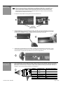
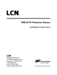
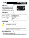
BODYGUARD III USER’S GUIDE PRESENCE SENSOR DESCRIPTION TECHNICAL SPECIFICATIONS The BEA Bodyguard III Presence Sensor (10BODYGUARDIII) is a self-monitored ready overhead-mounted diffused active infrared sensing device that provides detection for the triggering of automatic swing door safety functions. This sensor is designed for use with all of BEA’s LO-21 modules, as well as the Parallink and LO-Linx. When used with BEA’s lockout devices, the sensor is programmed to allow two different fields of detection - one for detection when the door is in the fully closed position and the other for detection when the door is fully open. While the door is in the fully open position, the Bodyguard extends its coverage back through the threshold area of the doorway, to provide coverage that will overlap with BEA’s motion sensors. As with all of BEA’s programmable sensing devices, full adjustability is achieved with the use of BEA’s hand-held remote control unit. This allows alteration of all of the available functions as well as for inquiry of existing settings. Should the need arise; the Bodyguard may also be tuned by means of two sensor-mounted buttons contained on the PC Board within the unit. With these two buttons, the Bodyguard’s field of detection can be altered without the use of the hand-held remote. If a complete door-mounted sensor (SuperScan) system is not used in addition to the Bodyguard, BEA, Inc. recommends the use of a lockout safety beam to allow safety signaling if the zone is entered during a door closing cycle. Installation Height - Variable Mounting Angles Bodyguard only Bodyguard with Bodymount Power Supply Frequency Output 9’-0” max. (recommended 6’-6” to 8’-0”) +5°, +10° (factory default setting: +5°) 0°, +5°, +10° 12 to 24 V AC / DC +/- 10% 50-60 Hz Max. Voltage at contacts: 60V DC / 125V AC Max. Current at contacts: 1 A Max. switching power: 30 W (DC), 60 VA (AC) 0.5 to 9 seconds -22°F to +140°F Immune to electrical and radio frequency interference 4’- six conductor cable 1lb. 11 oz. (765g) 11.8”L (305 mm.) x 1.9”H (51 mm.) x 1.9”W (46 mm.) Aluminum & ABS plastic Black anodized aluminum Relay Hold Time Operating Temperature Immunity Cable Weight Dimensions Material Housing Color COMPONENT ID Left Lens Red LED Right Lens Left End Cap Right End Cap Center Eye Shield 4’ Cable INSTALLATION TIPS 75.5134.10 EN 20110519 The sensor must be firmly fastened to prevent vibration. The sensor must not have any unwanted objects likely to move or vibrate in its path. The sensor should be mounted flush with bottom of door header. Page 1 of 13 SAFETY PRECAUTIONS • • • • • MECHANICAL INSTALLATION PREPARATION Shut off all power going to the header before attempting any wiring procedures. Maintain a clean & safe environment when working in public areas. Constantly be aware of pedestrian traffic around the door area. Always stop pedestrian traffic through the doorway when performing testing that may result in unexpected reactions by the door. Always check placement of all wiring and components before powering up to insure that moving door parts will not catch any wires and cause damage to equipment. To prepare the Bodyguard for mounting to the header, perform the following: a) Remove both end caps from the Bodyguard (Picture 1). Each is attached by one Phillips head screw. 1 2 b) Remove both lenses from Bodyguard by simply sliding them out at each end (Picture 2). c) Remove the center eye shield (Picture 3) (take care not to damage the light tube on the inner side of the shield). Simply pull out from the top end and rotate out as shown below. 3 d) MECHANICAL INSTALLATION – PLACEMENT OF THE SENSOR 4 Slide the PCB out of the extrusion and set it aside (Picture 4). Remember these guidelines when installing a Bodyguard: The Bodyguard should be mounted at a height range of 6’ 6” to 8’. Maximum mounting height is 9’. The Bodyguard should be mounted above the door on the swing side. The Bodyguard shall be mounted flush with the bottom of the automatic door header. This is absolutely necessary to allow the detection pattern to reach back through the threshold area when the bodyguard is in the open door position. For SINGLE DOOR APPLICATIONS, the Bodyguard should be mounted at the center of the door opening. However, if this is not possible, the unit may be installed off-center. In such cases, pattern location will have to be altered for proper placement of the field of detection. Try to avoid mounting locations that may pose potential problems such as directly over a door arm. For DOUBLE-EGRESS APPLICATIONS, one Bodyguard should be mounted over each swing-path. There should be at least 40” of separation between the 2 Bodyguards when measured between the centerline of each sensor. If the Bodyguard sensor is the only sensor being used for safety at the swing side of the door, to be in compliance with ANSI 156.10, a lockout safety beam or door mounted safety side Superscan(s) is needed in addition to the Bodyguard sensor. Wall Switch 20” min CAUTION: FOR ALL APPLICATIONS, REFER TO THE PATTERN CHARTS FOR WIDTH AND DEPTH IN THE APPLICABLE SECTION OF THIS GUIDE. PATTERNS SHALL BE ADJUSTED TO ACHIEVE MAXIMUM DETECTION ZONES, AND SHALL BE IN COMPLIANCE WITH ALL APPLICABLE SAFETY STANDARDS (I.E. ANSI A156.10). 75.5134.10 EN 20110519 20” min Bodyguard Bodyguard Wall Switch Page 2 of 13 MECHANICAL INSTALLATION NOTE: BEA, Inc. recommends the use of a BodyMount for most Bodyguard applications. The BodyMount is a 3” standoff that allows the Bodyguard to be slightly distanced from the face of the closed door. This helps to prevent ghosting caused by slight door movement while closed, and also prevents ghosting when SuperScan sensors are used (as the SuperScan extrusions at the top of the door are extremely close to the sensor while the door is closed). 1. The extrusion has pre-drilled mounting holes at each end (Pictures 5 & 6). 5 6 Pre Drilled Mounting Holes Approx. 9 ¾” Apart 2. Hold the Bodyguard up to the pre-determined location, and attach using the 2 self-drilling screws that are included with the package (Picture 7). It may be necessary to pre-drill a pilot hole (Picture 8) in the header for ease of screw installation. Ensure that Bodyguard is mounted securely at each end. 7 3. 8 If Bodyguard is mounted directly to door header, and cabling is to pass directly into header, drill a ¼” hole next to the Bodyguard’s left side end cap to allow wire passage into header (Picture 9). The wire passage hole should be in a location that aligns with the cut out in the end cap (Picture 9). 9 ELECTRICAL INSTALLATION AND CABLING 1. Once the Bodyguard is securely attached to header, cabling & wiring may be completed. Wire the 7-pin terminal block OR use the cable that is provided for use with the 10-pin connector (Picture 10). If wiring the Bodyguard to a BEA module, such as an LO-21 or an MC15. Refer to the schematic for the respective module. For ease of installation, wire the terminal before attaching it to the Bodyguard. 10 RED BLACK WHITE GREEN BROWN BLUE 1 PWR 2 PWR 3 COM 4 NO 5 NC 6 IN 7 IN + Position 1 2 10 PIN 10 PIN 75.5134.10 EN 20110519 3 4 5 6 7 Connection 7-Pin 12 to 24 V AC / DC +/- 10% 24 to 24 V AC / DC +/- 10% Common Normally Open Normally Closed Data Data + Wire Color (10-pin cable) Red Black White Green Brown Blue Page 3 of 13 ELECTRICAL INSTALLATION AND CABLING (Continued) 2. Attach the terminal block to the Bodyguard (Picture 11). 11 MECHANICAL ADJUSTMENTS 3. With the terminal block attached to the Bodyguard, feed the opposite end of the cable through the previously drilled wire passage hole, and on into the header. Pull the cable all the way through and route it to the location of the automatic door control. Refer to the respective User’s Guide for the BEA product you are interfacing with. Ensure a dedicated power source of 12 or 24 V AC / DC +/- 10% (BEA PN: 1024VAC may be used for powering this product). 1. Once all installation, wiring and cabling procedures have been completed, mechanical adjustments can be made. Please note that further adjustments may be required after powering and walk testing the detection field. 2. Aside from placement on the header, the only mechanical adjustment that may be made to the sensor is the angle adjustment. The Bodyguard is factory pre-set to the +5º position, but may be reduced to a 0º position or increased to a 10º position. The greater the angle, the farther from the door the pattern will be. The 0º angle should only be used when the Bodyguard is mounted to a BodyMount block or to a soffett above the door that extends out from the face of the safety side of the door – in this case, the 0º setting would improve the location of the detection field across the threshold area of the doorway. It is recommended that for most applications, the unit be powered and walk tested at the pre-set 5º angle. After walk testing, if the detection field needs to be changed, then proceed with changes to the angle setting as shown below. 3. To change the angle setting the end caps, lenses, and center eye shield must be removed (as shown on page 2). The terminal block must also be removed if it has been wired. Once removed release the white clips, as shown below, and rotate outward to remove the PCB (Pictures 12 & 13). 12 4. 13 Once the PCB is completely removed from the housing, the angle position may be changed. There are two clips per Bodyguard and the angle must match for each clip on the same PCB. The positions are shown below. 5° 0° 10° Factory Default 5. Slide the left and right lens back into place (Picture 14) and proceed with power-up procedures. Leave the end caps off until all final adjustments have been made. 14 75.5134.10 EN 20110519 Page 4 of 13 POWER-UP PROCEDURES 1. Upon completion of mechanical and electrical installation, apply 12 to 24 V AC / DC +/- 10% to the Bodyguard, with the door in the closed position. The Bodyguard will flash a green LED at a rate of 2 Hz, then it will expire upon a successful set-up in the door-closed position. NOTE: If applying the Bodyguard to a door control that requires a learn cycle upon powering, it is recommended to allow the doors to complete a learn cycle before applying power to the Bodyguard. 2. Activate the door to the full open position. When used with BEA’s lockout relay, the Bodyguard will once again flash the green LED and will execute a door-open set-up. Upon completion of the set-up for the door-open position, the doors will begin closing. Normal operation should resume thereafter. Proceed with fine-tuning to insure compliance with all applicable safety standards (i.e. ANSI A156.10). If set-up is unsuccessful, refer to the Troubleshooting Guide at the end of this Users Guide, and also to the guide located at the end of the respective lockout User’s Guide. HELPFUL HINT: #1: Once the sensor is powered up, and completes a setup for the closed door position, activate the door to the open position as indicated above. During this first open cycle, if the sensor does not begin to flash green once the door is full open, a data problem is highly likely. If the door went open and the sensor just stayed red, in detection, it probably did not get the correct data signal from the respective lockout module. As a preliminary check to the troubleshooting, be sure to check the following: a) The white wire from the lockout needs to go to terminal 6 at the Bodyguard, AND the red/white striped wire needs to go terminal 7 at the Bodyguard. If these two wires are swapped, the Bodyguard will NOT work correctly. b) Check to ensure that the voltage from the motor (at the red and black wire of the lockout) has at least 10 volts DC. A voltage that is too low may not be recognized by the lockout. #2: If the door goes to the open position and a setup is completed successfully, but then the door begins to close and immediately recycles open, it is possible that the Bodyguard’s detection of the closing door is causing a recycle. Be sure to check dipswitch 6, if using an LO21B, U, or P: dipswitch #6 on these modules is typically ON for applications where the red and the black wire are connected to a motor. In these applications the lockout expects to see a voltage on these wires when the door is in the OPEN position. Only specific applications, such as a Besam Swingmaster MP (with CUP control) may require the switch to be in the OFF position. Additionally, always make sure that the red wire from the lockout goes to the positive leg of the motor (or switch) and the black wire goes to the negative leg. If these wires are backwards, the system will NOT work correctly. NOTE: Always be sure to refer to the applicable lockout User’s Guide for more detailed information. DUEL EGREES: REDUCING CROSS TALK Perform the following set up using BEA’s remote control to reduce cross talk between duel egress applications. Refer to the figure on page 2 to ensure the two Bodyguards are installed with at least 40” of separation when measured between the centerline of each sensor. 1. Place doors in the hold open position. Unlock sensor and set open door Pattern Depth to 5 (Medium Pattern). This sequence will turn off threshold IR while door is in open position. This function should be changed on both sensors: + 2. then + The infrared frequency function may need to be changed. Change frequency on one of the sensors: + 3. + + then + Change to a different mode in applications where high gloss floors or multiple doors are installed in vestibules. Change sensor one to: + + then + then + Change sensor two to: + 75.5134.10 EN 20110519 + Page 5 of 13 BEA’S UNIVERSAL REMOTE CONTROL The Bodyguard is fully compatible with BEA’s Remote Control as shown below. Use of the remote control should be conducted within 10’ – 15’ of the sensor, and the remote should be pointed directly at the sensor when used. Refer to the ‘Programming Guide’ in the following section for each parameter and its values. Additional program notes: 1. The Bodyguard is capable to have two patterns (door closed and door open) that are independently adjustable. Thus, when programming, it is necessary to adjust the pattern for door closed, and then to adjust the pattern again when the door is open. The following functions may be independently adjusted for each door position: 2. The following functions apply to both door closed and door open positions: 75.5134.10 EN 20110519 Sensitivity Pattern Width Pattern Depth Automatic Learn Time Immunity Frequency Output Configuration Door Control Mode Hold Time Interface Type 3. The immunity modes include Medium (Rain) and High (Snow). During these modes, learn time of the sensor will not be affected. These modes affect the interpretation of the objects in the field of detection relative to the background. 4. MP mode set by the remote control, allows for a Besam MP Control specific setting. This setting is set to a default of ‘0’ which allows Bodyguard to operate normally with any control, and when set to a Besam specific setting of ‘1’ when used with a Besam MP control. Page 6 of 13 PROGRAMMING GUIDE – GENERAL FUNCTIONS Number Keys Number keys (0 through 9) are used for assigning a value for a given function Infrared Frequency 1 2 3 4 Interface 1: New Style 2: LO21 - Old Style (LO21, B, K, P, S, U, LO-LINX, MC15, DP-HUB) Mode Normal Normal Quiet Quiet Frequency Low High Low High See QUIET MODE Door Control Unlock 1: Normal (LED in normal mode) 2: Door permanently open (Red LED ON) 3: Door permanently closed (Red LED OFF) Inquire Lock To UNLOCK the sensor: Press the UNLOCK key once. Red LED flashes slowly. If flashing fast, see Note below. Output Configuration To LOCK the sensor: Press the LOCK key twice, OR press once then followed by a 4digit lock code. If less than 4 digits, press lock again after the last digit. LED goes out when complete. 1 – Normally Open Relay 2 – Normally Closed Relay Setup To INQUIRE the sensor: Unlock the sensor, press the desired function key, followed by the INQUIRY key – the number of green flashes corresponds to the value. Note: If sensor is locked, but code is unknown, power the sensor off and then back on. Press the UNLOCK key within 60 seconds. Re-lock with 0000. This is the default code. Sensor will unlock with one press of the unlock key, when set to 0000. launch a quick setup restore factory defaults Hold Tme 0 (0.5s) → 9 (9s) launch a closed door setup launch an open door setup See AUTOMATIC SETUP AUTOMATIC SETUP: When performing an automatic setup (setup key pressed twice in a row), the sensor will begin to flash green during the door closed position, and will continue to do so until the door is activated to the open position. The LED will then go out and the door will close. The LED will flash green again at the closed position until a setup is complete. Upon the next activation, the sensor will launch another setup for the open door position, and will begin normal operation thereafter. QUIET MODE: The QUIET mode uses a different pulsing pattern to avoid interference with other infrared systems. The NORMAL mode transmits more energy and detects slightly in a more crisp fashion. The NORMAL mode is recommended for installations with only one door. 75.5134.10 EN 20110519 Page 7 of 13 PROGRAMMING GUIDE – PATTERN ADJUSTMENTS Modes of Operation 0: Normal 1 : MP mode 2 : Record mode Sensitivity Door Open-Closed 0 (min) → 9 (max) (default 7 for door open, default 6 for door closed) Pattern Width Door Open or Closed 1: Wide (closed door) 2 : Middle (open door) 3 : Asymmetric Left Narrow 4 : Asymmetric Right Narrow 5 : Narrow Left 6 : Narrow Right 7 : Asymmetric Left Wide 8 : Asymmetric Right Wide 9 : Center Narrow See PATTERN WIDTH or DEPTH Automatic Learn Time 0: 30 seconds 1: 1 minute 2: 2 minutes 3: 3 minutes 4: 5 minutes 5: 7 minutes 6: 10 minutes 7: 15 minutes 8: 10 seconds 9: Infinity – no learn Immunity 1: Low (Normal) 2 : Medium - Rain (Disregards more floor disturbances) 3 : High - Snow (Disregards greatest floor disturbances) Pattern Depth 1: Deep – Threshold ON 2 : Medium – Threshold ON (open) 3 : Limited – Threshold ON 4 : Deep – Threshold OFF 5 : Medium – Threshold OFF (closed) 6 : Limited – Threshold OFF See THRESHOLD See PATTERN WIDTH or DEPTH THRESHOLD: The Threshold is always OFF when the door is closed. PATTERN WIDTH OR DEPTH: When pattern width or depth is changed, a setup of the new pattern size will automatically be triggered once a value key has been pressed. 75.5134.10 EN 20110519 Page 8 of 13 MANUAL (NON-REMOTE) SET-UP Without the BEA Remote Control, the Bodyguard may be set up using the manual push buttons (see diagram below) located under the right end cap. ONLY THE SENSITIVITY, RELAY MODE, AUTO-LEARN TIME, PATTERN WIDTH, AND PATTERN DEPTH MAY BE ADJUSTED WITH THE MANUAL PUSH BUTTONS. To adjust the Bodyguard, complete the following: PB1 PB2 1. To start the set-up process, press PB1 (for less than 2 seconds) The set-up function will be launched according to the current door position. The green LED will flash at 2+/- Hz for 10 seconds. This LED will stop flashing once a successful set-up is achieved. If there is an interruption to the field of detection during this procedure, the green LED will flash at a slower rate. Press PB1 to re-launch the set-up. 2. To change the detector’s parameters, press PB1 (for more than 2 seconds), then release. 3. Press either PB1 or PB2. The LED will immediately flash red, followed by a sequence of green flashes. 4. The red flashes indicate the parameter and the green flashes indicate the setting of the particular parameter. NOTE: Pressing PB1 will toggle between the parameters and pressing PB2 will toggle between the range of adjustments for that particular setting. Once you achieve the highest adjustment, the value will roll over to the lowest setting, upon the next press of PB2. A zero value will result in no flash of the LED. To exit manual set-up, simply wait 20 seconds or press PB1 for more than 2 seconds. Replace the right end cap back on the Bodyguard. Use the chart below as a reference for the manual set-up process. RED LED STATUS 75.5134.10 EN 20110519 PARAMETER DESCRIPTION GREEN LED STATUS 1 Red Flash 1 Sensitivity (Door open) 0 – 9 Green Flashes (default = 7) 2 Red Flashes 2 Sensitivity (Door closed) 0 – 9 Green Flashes (default = 6) 3 Red Flashes 3 Output Configuration 1 – 2 Green Flashes (default = 1) 4 Red Flashes 4 Auto Learn Time 0 – 9 Green Flashes (default = 0) 5 Red Flashes 5 Pattern Width (Door Open) 0 – 9 Green Flashes (default = 2) 6 Red Flashes 6 Pattern Width (Door Closed) 0 – 9 Green Flashes (default = 1) 7 Red Flashes 7 Pattern Depth (Door Open) 1 – 6 Green Flashes (default = 1) 8 Red Flashes 8 Pattern Depth (Door Closed) 1 – 6 Green Flashes (default = 1) Page 9 of 13 BODYGUARD WIDTH PATTERNS st 1 2 3 4 5 1 Row of Infrared 6 Threshold 7 8 9 10 11 12 2 Row of Infrared 13 14 15 16 17 18 3 Row of Infrared 19 20 21 22 23 24 4 Row of Infrared (1) Wide Pattern (2) Middle Pattern rd th (3) Asymmetric Left Narrow 1 2 3 4 5 6 1 2 3 4 5 6 1 2 3 4 5 6 7 8 9 10 11 12 7 8 9 10 11 12 7 8 9 10 11 12 13 14 15 16 17 18 13 14 15 16 17 18 13 14 15 16 17 18 19 20 21 22 23 24 19 20 21 22 23 24 19 20 21 22 23 24 (4) Asymmetric Right Narrow (5) Left Narrow (6) Right Narrow 1 2 3 4 5 6 1 2 3 4 5 6 1 2 3 4 5 6 7 8 9 10 11 12 7 8 9 10 11 12 7 8 9 10 11 12 13 14 15 16 17 18 13 14 15 16 17 18 13 14 15 16 17 18 19 20 21 22 23 24 19 20 21 22 23 24 19 20 21 22 23 24 (7) Asymmetric Left Wide BODYGUARD DEPTH PATTERNS nd (8) Asymmetric Right Wide (9) Center Narrow 1 2 3 4 5 6 1 2 3 4 5 6 1 2 3 4 5 6 7 8 9 10 11 12 7 8 9 10 11 12 7 8 9 10 11 12 13 14 15 16 17 18 13 14 15 16 17 18 13 14 15 16 17 18 19 20 21 22 23 24 19 20 21 22 23 24 19 20 21 22 23 24 Row 1 (spots 1 through 6), remain on, even during the closed door position (1) Deep (2) Middle (3) Limited 1 2 3 4 5 6 1 2 3 4 5 6 1 2 3 4 5 6 7 8 9 10 11 12 7 8 9 10 11 12 7 8 9 10 11 12 13 14 15 16 17 18 13 14 15 16 17 18 13 14 15 16 17 18 19 20 21 22 23 24 19 20 21 22 23 24 19 20 21 22 23 24 NOTE: When the Bodyguard is mounted at 7’, each block on the pattern charts shown above equates to a size of approximately 14” x 14”. Pattern sizes shown are only as an approximation. Always walk-test the pattern once complete, to insure compliance with all applicable safety and performance standards. 75.5134.10 EN 20110519 Page 10 of 13 BODYGUARD DEPTH PATTERNS Cont. Row 1 (spots 1 through 6), are on during open door position and off during closed door position. (4) Deep Without Row 1 TROUBLESHOOTING (5) Middle Without Row 1 (6) Limited Without Row 1 1 2 3 4 5 6 1 2 3 4 5 6 1 2 3 4 5 6 7 8 9 10 11 12 7 8 9 10 11 12 7 8 9 10 11 12 13 14 15 16 17 18 13 14 15 16 17 18 13 14 15 16 17 18 19 20 21 22 23 24 19 20 21 22 23 24 19 20 21 22 23 24 PROBLEM PROBABLE CAUSE CORRECTIVE ACTION Bodyguard will not set-up upon initial powering 1. Improper input voltage 2. Bodyguard is in detection 3. Potential interferences from high intensity lighting 1. Check terminals 1 & 2 for proper voltage 12 to 24 V AC/DC + 10%. 2. Make certain that the field of detection is all clear during the set-up and that all lenses are installed on the Bodyguard. If detection is encountered upon initial set-up, the Bodyguard will continuously flash Green at + 2 Hz. The Bodyguard will also not set-up if permanent stationary objects are extremely close to the sensor. Ensure that, not only is the detection field all clear, but that the sensor is mounted properly (using the Bodyguard mounting block if NECESSARY). 3. Ensure that no high intensity lighting is in the immediate area of the sensor. Door will not open once setup has been completed. 1. Bodyguard is in detection. 2. Improper wiring 3. Lockout safety beams are in detection 4. Improper relay output configuration 1. Ensure that there is no detection occurring at the Bodyguard. If the Red LED is on steady, there is detection. Make sure there have been no changes in the field of detection since set-up. If permanent changes have occurred, launch a new setup and re-test door. CAUTION: THERE POSSIBLY MAY BE NO SAFETY ON THE DOOR WHEN THIS TEST IS PERFORMED. 2. Remove the output wires (common, normally open, normally closed) from the Bodyguard. Activate the door control, if the door opens, the fault exists with Bodyguard or related wiring. If door does not open, the faults may exist with the door control or it’s related wiring. 3. Disconnect the green & blue wires from the LO-21 to the door control safety and common terminals. If door opens when triggered, fault lies within the lockout safety beam set, or possibly with the LO-21. Refer to the LO-21 troubleshooting procedures in the respective manual. 4. Ensure proper relay output setting. Refer to page 6. Typically, relay setting should be ‘Normally Open’. This means the relay would close upon detection. 75.5134.10 EN 20110519 Page 11 of 13 TROUBLESHOOTING – Cont. PROBLEM Bodyguard repeatedly relearns the environment with each door position. Bodyguard not reacting to the remote control PROBABLE CAUSE CORRECTIVE ACTION 1. Improper data from the lockout device 2. Data polarity at the Bodyguard is incorrect 1. Allow the door to open in the automatic mode. Unlock the Bodyguard and launch a setup by pressing the Setup key, followed by the number 2. If the sensor does not begin flashing green, and instead goes back to a red indication, improper data exists. Refer to respective lockout User’s Guide for troubleshooting. 2. Check for proper polarity at terminal 6 and 7. The negative wire from the lockout (white) should be connected to terminal 6, and the red/white striped wire from the lockout should connect at terminal 7. HELPFUL HINT: If faulty data is suspected, simply power the door to the open position (by activation OR with the use of a hold open switch). While the door is open, unlock the Bodyguard, and press the setup key, followed by the number 2. If the sensor goes back to a red LED (as opposed to flashing the green LED to indicate a setup), there is a strong probability that the data is incorrect. Refer then to the respective lockout User’s Guide for troubleshooting help. 1. Batteries in the remote control are dead. 2. Distance between sensor and remote is too far. 1. Replace batteries in the remote control 2. Move in closer to the sensor when programming. 3. If remote control fails, manual programming procedures may have to be used (See Pg. 8). HELPFUL HINT: Use BEA’s Spotfinder to test the output of the remote control. Simply point the remote at the IR Spot on the Spotfinder, press the Unlock key on the remote, and red LED should illuminate. ACCESSORIES BODYMOUNT LOCKOUT SAFETY BEAM / SBK-30 DP-HUB (edps) SPOTFINDER BODYGUARD QUICK DISCONNECT HARNESS (20.5128) BR3 INTERFACE MODULE 75.5134.10 EN 20110519 Page 12 of 13 ANSI / AAADM Compliance ANSI / AAADM COMPLIANCE STATEMENT AAADM American Association of Automatic Door Manufactures Upon finishing the installation and/or service work perform at a minimum a daily safety check in accordance with the minimum inspection guidelines provided by AAADM. Provide each owner with an owner’s manual that includes a daily safety checklist and contains at a minimum the information recommended by AAADM. Offer a familiarization session with the owner explaining how to do daily inspections and calling out location of cutoff switches to put equipment out of service if a deficiency is noted. The equipment should be inspected in accordance with the minimum inspection guidelines annually. A safety check that includes at a minimum the items listed on the safety information label must be performed during each service call. If you are not an AAADM certified inspector BEA strongly recommends to have an AAADM certified inspector perform an AAADM inspection and placing a valid inspection sticker below the safety information label prior to placing the equipment into operation. COMPANY CONTACT 75.5134.10 EN 20110519 Page 13 of 13