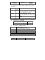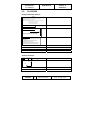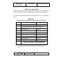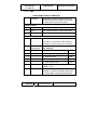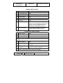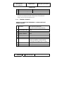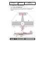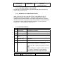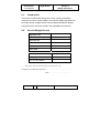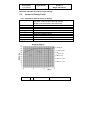
1
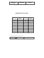
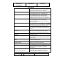
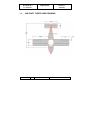
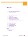
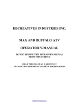
PIONEER 200 Aircraft
FLIGHT MANUAL
__________________________________________
Document N° F2-1.0/R80/F/EU Dated 20-04-2002
Cover page
MANUFACTURER : ALPI AVIATION S.r.l.
Address :
City :
Country :
Via dei Templari, 24
33080 San Quirino (PN)
Italy
Web Site : www.alpiaviation.com
Telephone:
E - mail :
+39 0434 37 04 96
[email protected]
AIRCRAFT TYPE & MODEL
Type :
Pioneer
Model : 200
Aircraft Mark :
Aircraft S/N :
By : www.aeroprogetti.net
Pioneer 200
Flight Manual
Document N° :
Section: 0
F2-1.0/R80/F/EU
TABLE OF CONTENTS
SECTION
General
1
Limitations
2
Emergency Procedures
3
Normal Procedures
4
Performance
5
Weight and Balance Statement
6
This page will change with all revision issues
REVISION :
By :www.aeroprogetti.net
0
Dated: 20-04-2002
Sect : 0 -Page: 1 of 8
Document N° :
Pioneer 200
Flight Manual
Section: 0
F2-1.0/R80/F/EU
AMENDMENT RECORD SHEET
Revision No.
Page(s)
affected
0
All pages
Signature.
Date of
Incorporation
20-03-02
This page will change with all revision issues
REVISION :
By :www.aeroprogetti.net
0
Dated: 20-04-2002
Sect : 0 -Page: 2 of 8
Document N° :
Pioneer 200
Flight Manual
Section: 0
F2-1.0/R80/F/EU
INTRODUCTION
This Flight Manual applies only to the particular aircraft identified by the registration
marking and serial number on the Cover Page and contains the airworthiness
limitations and essential operating data for this aircraft.
The Flight Manual shall be carried in the aircraft on all flights.
Special operations requiring additional limitations and instructions are listed in the
"Supplements Section" and this section shall be consulted before undertaking any
such operations. For operating information not included in this manual, reference
should be made to the appropriate operations or manufacturer's manuals.
The pilot in command the aircraft shall comply with all requirements, procedures
and limitations with respect to the operation of the aircraft set out in the Flight
Manual for the aircraft.
Amendments shall be issued by Alpi Aviation as necessary and will take the form of
replacement pages, with the changes to the text indicated by a vertical line in the
margin together with the amendment date at the bottom of the page.
Interim/Temporary amendments may be issued in the same manner and are to be
inserted as directed. These amendments will be issued on coloured pages and will
take precedence over the stated affected page. It is the owner's responsibility to
incorporate in this manual all such amendments, and to enter the date of
incorporation and his signature on the appropriate Amendment Record Sheet.
No entries or endorsements may be made to this Flight Manual except in the
manner and by persons authorised for the purpose.
REVISION :
By :www.aeroprogetti.net
0
Dated: 20-04-2002
Sect : 0 -Page: 3 of 8
Document N° :
Pioneer 200
Flight Manual
Section: 0
F2-1.0/R80/F/EU
REVISIONS
It is the responsibility of the owner to maintain this Manual in a current status when
it is being used for operational purposes.
Owners should contact Alpi Aviation S.r.l. whenever the revision status of their
Manual is in question.
A revision bar will extend the full length of new or revised text and/or illustrations
added on new or presently existing pages. This bar will be located adjacent to the
applicable revised area on the outer margin of the page.
All revised pages will carry the revision number and the date on the applicable
page.
The following List of Effective Pages provides the dates of issue for original and
revised pages, and a listing of all pages in the Manual. Pages affected by the
current revision are indicated by an asterisk (*) preceding the pages listed.
REVISION :
By :www.aeroprogetti.net
0
Dated: 20-04-2002
Sect : 0 -Page: 4 of 8
Pioneer 200
Flight Manual
Document N° :
Section: 0
F2-1.0/R80/F/EU
LIST OF EFFECTIVE PAGES
Page
0-1
0-2
0-3
0-4
0-5
0-6
0-7
0-8
1-1
1-2
1-3
1-4
1-5
1-6
The dates of issue for original & revised pages are:
Rev.
Date
Page
Rev.
Date
Page
Section 0
Section 3
0
20-04-02
3-1
0
20-04-02
5-1
0
20-04-02
3-2
0
20-04-02
5-2
0
20-04-02
3-3
0
20-04-02
0
20-04-02
3-4
0
20-04-02
0
20-04-02
3-5
0
20-04-02
0
20-04-02
3-6
0
20-04-02
0
20-04-02
3-7
0
20-04-02
0
20-04-02
3-8
0
20-04-02
3-9
0
20-04-02
6-1
3-10
0
20-04-02
6-2
3-11
0
20-04-02
6-3
3-12
0
20-04-02
6-4
3-13
0
20-04-02
3-14
Section 1
0
20-04-02
0
20-04-02
0
20-04-02
0
20-04-02
0
20-04-02
0
20-04-02
4-1
4-2
4-3
4-4
4-5
4-6
4-7
4-8
4-9
Section 2
2-1
0
20-04-02
4-10
2-2
0
20-04-02
4-11
2-3
0
20-04-02
4-12
2-4
0
20-04-02
4-13
2-5
0
20-04-02
4-14
2-6
0
20-04-02
4-15
2-7
0
20-04-02
4-16
2-8
0
20-04-02
4-17
4-18
This page will change with all revision issues
REVISION :
By :www.aeroprogetti.net
0
Rev.
Date
Section 5
0
20-04-02
0
20-04-02
Section 6
0
20-04-02
0
20-04-02
0
20-04-02
0
20-04-02
Section 4
0
20-04-02
0
20-04-02
0
20-04-02
0
20-04-02
0
20-04-02
0
20-04-02
0
20-04-02
0
20-04-02
0
20-04-02
0
20-04-02
0
20-04-02
0
20-04-02
0
20-04-02
0
20-04-02
0
20-04-02
0
20-04-02
0
20-04-02
0
20-04-02
Dated: 20-04-2002
Sect : 0 -Page: 5 of 8
Pioneer 200
Flight Manual
Document N° :
Section: 0
F2-1.0/R80/F/EU
DEFINITIONS
AIRFIELD PRESSURE ALTITUDE
The Airfield Pressure Altitude is that altitude registered
at the surface of the aerodrome by an altimeter with
the pressure subscale set to 1013 millibars
INDICATED AIRSPEED (I.A.S.)
Indicated airspeed, which is the reading obtained from
an airspeed indicator having no calibration error.
TAKEOFF SAFETY SPEED
The Takeoff Safety Speed is a speed chosen to
ensure that adequate control will exist under all
conditions, including turbulence and sudden and
complete engine failure, during the climb after takeoff.
LANDING SAFETY SPEED
The Landing Safety Speed is the speed chosen to
ensure that adequate control will exist under all
conditions, including turbulence, to carry out normal
flare and touchdown.
NORMAL OPERATING SPEED
This speed shall not normally be exceeded.
Operations above the Normal Operating Speed shall
be conducted with caution and only in smooth air.
Va
Maximum for manoeuvres involving an approach to
stall conditions or full application of the primary flight
controls.
MANOEUVRING SPEED
KCAS KNOTS CALIBRATED
AIRSPEED
Indicated airspeed corrected for position and
instrument error and expressed in knots. KCAS is
equal to KTAS in standard atmosphere at sea level
KIAS KNOTS INDICATED
AIRSPEED
The speed shown on the airspeed indicator and
expressed in knots.
KTAS
The airspeed expressed in knots relative to
undisturbed air which is KCAS corrected for altitude
and temperature.
KNOTS TRUE AIRSPEED
V fe MAXIMUM FLAP EXTENDED
SPEED
The highest speed permissible with wing flaps in the
prescribed extended position.
V no MAXIMUM STRUCTURAL
CRUISING SPEED
The speed that should not be exceeded except in
smooth air, and then only with caution.
V ne NEVER EXCEED SPEED
The speed limit that may not be exceeded at any time.
V s0
STALLING SPEED
The stall speed or minimum steady flight speed at
which the airplane is controllable in a specified
configuration.
V so
STALLING SPEED
The stall speed or minimum steady flight speed at
which the airplane is controllable in the landing
configuration at the most forward centre of gravity.
LANDING CONFIGURATION
REVISION :
By :www.aeroprogetti.net
0
Dated: 20-04-2002
Sect : 0 -Page: 6 of 8
Pioneer 200
Flight Manual
Document N° :
Section: 0
F2-1.0/R80/F/EU
V x BEST ANGLE-OF-CLIMB
SPEED
The speed which results in the greatest gain of altitude
in a given horizontal distance.
Vy
The speed which results in the greatest gain in altitude
in a given time.
BEST RATE-OF-CLIMB SPEED
METEOROLOGICAL TERMINOLOGY
OAT OUTSIDE AIR
TEMPERATURE
The free static air temperature. It is expressed in either
degrees Celsius or degrees Fahrenheit.
STANDARD TEMPERATURE
Standard Temperature is 15 degrees C at sea level
pressure altitude.
PRESSURE ALTITUDE
The altitude read from the an altimeter when the
altimeter's barometric scale has been set to 1013 mb
(29.92 inches of mercury).
ENGINE POWER TERMINOLOGY
BHP
BRAKE HORSEPOWER
The power developed by the engine.
RPM REVOLUTIONS PER MINUTE
Engine speed.
STATIC RPM
The engine speed attained during a full-throttle engine
runup when the airplane is on the ground and
stationary.
AIRPLANE PERFORMANCE AND FLIGHT PLANNING TERMINOLOGY
MAXIMUM CROSSWIND VELOCITY
The velocity of the crosswind component for which
adequate control of the airplane during takeoff and
landing was actually demonstrated during the
certification tests. The value shown is limiting.
USEABLE FUEL
The fuel available for flight planning
UNUSABLE FUEL
The quantity of fuel that cannot be safely used in flight
LPH
LITRES PER HOUR
NMPL
LITRE
The amount of fuel ( in litres ) consumed per hour
NAUTICAL MILES PER
g
The distance ( in nautical miles ) which can be
expected per litre of fuel consumed at a specific
engine power setting and/or flight configuration.
The acceleration due to gravity.
REVISION :
By :www.aeroprogetti.net
0
Dated: 20-04-2002
Sect : 0 -Page: 7 of 8
Pioneer 200
Flight Manual
Document N° :
Section: 0
F2-1.0/R80/F/EU
WEIGHT AND BALANCE TERMINOLOGY
STATION
Only two load stations are specified: ie Seat Station
which is the centre of the fixed seats and Fuel Station
which is the centre of the fixed fuel tank.
C.G.
The point at which an airplane, or equipment, would
balance if suspended.
CENTRE OF GRAVITY
C.G. LIMITS
The extreme centre of gravity locations within which
the airplane must be operated at a given weight.
STANDARD EMPTY WEIGHT
The weight of a standard airplane, including unusable
fuel, full operating fluids and full engine oil.
BASIC EMPTY WEIGHT
The standard empty weight plus the weight of optional
equipment.
USEFUL LOAD -
The difference between ramp weight and the basic
empty weight.
MTOW MAXIMUM TAKEOFF
WEIGHT
The maximum weight approved for the start of the
takeoff run.
REVISION :
By :www.aeroprogetti.net
0
Dated: 20-04-2002
Sect : 0 -Page: 8 of 8
Pioneer 200
Flight Manual
Document N° :
Section: 1
General
F2-1.0/R80/F/EU
Section1 - General
Table of Contents
1.1.
AIRCRAFT THREE VIEW DRAWING
2
1.2.
TECHNICAL DATA
4
1.2.1. ENGINE
4
1.2.2. PROPELLER
4
1.2.3. APPROVED FUEL TYPES AND GRADES
4
1.2.4. FUEL CAPACITY
4
1.2.5. APPROVED OIL GRADES
5
1.2.6. COOLANT
5
1.2.7. OIL CAPACITY
5
1.2.8. TYRE INFLATION PRESSURES
5
REVISION :
0
Dated: 20-04-2002
Sect : 1 -Page: 1 of 6
Document N° :
Pioneer 200
Flight Manual
Section: 1
General
F2-1.0/R80/F/EU
1.1.
AIRCRAFT THREE VIEW DRAWING
REVISION :
0
Dated: 20-04-2002
Sect : 1 -Page: 2 of 6
Document N° :
Pioneer 200
Flight Manual
Section: 1
General
F2-1.0/R80/F/EU
Ground Turning Radius = 6 metres.
REVISION :
0
Dated: 20-04-2002
Sect : 1 -Page: 3 of 6
Pioneer 200
Flight Manual
Document N° :
Section: 1
General
F2-1.0/R80/F/EU
1.2.
TECHNICAL DATA
1.2.1.
ENGINE
Manufacturer:
ROTAX GmbH
Aircraft Engine
Type:
1.2.2.
912 UL Series liquid cooled
PROPELLER
Manufacturer:
TONINI
Type:
Fixed Pitch Wooden
GT 166X142
Diameter:
166 cm
Pitch:
142 cm
1.2.3.
APPROVED FUEL TYPES AND GRADES
-UNLEADED MOGAS (98 Octane or greater - 90 RON or greater)
-100 LL or 100/130 grade aviation gasoline
(only for short utilization time, with carbon level inspection)
1.2.4.
FUEL CAPACITY
Total:
54 Litres
Useable
50 Litres
REVISION :
0
Dated: 20-04-2002
Sect : 1 -Page: 4 of 6
Pioneer 200
Flight Manual
Document N° :
Section: 1
General
F2-1.0/R80/F/EU
1.2.5.
APPROVED OIL GRADES
Motorcycle oil of a registered brand with gear additive
Specification
Exemples :
API classification "SJ" or "SG"
Shell - Advance VSX 4 (SAE 20W-40)
Castrol - Syntetic Blend (SAE 5W-50)
Shell - Synthetic Blend (SAE 10W-30)
For temp. Above and belove stated check Rotax engine manuals
For AVGAS use chech Rotax engine manuals
1.2.6. COOLANT
Antifreeze concentrate with additives against corrosion should be used with 50%
water in normal condition, and down 20% water in cold environment.
Capacity
Overflow or filler tank
1.2.7.
Max 2,3 litres
Max 0,2 lt
Min 2,2 litres
Min 0,1 lt
OIL CAPACITY
Sump capacity is : 3 Litres
1.2.8.
REVISION :
TYRE INFLATION PRESSURES
Standard Mains:
bar = 2.2 (psi = 32.3)
Nose:
bar = 2.2 (psi = 32.3)
0
Dated: 20-04-2002
Sect : 1 -Page: 5 of 6
Document N° :
Pioneer 200
Flight Manual
Section: 1
General
F2-1.0/R80/F/EU
INTENTIONALLY LEFT BLANK
REVISION :
0
Dated: 20-04-2002
Sect : 1 -Page: 6 of 6
Pioneer 200
Flight Manual
Document N° :
Section: 2
Limitations
F2-1.0/R80/F/EU
Section 2 - Limitations
Table of Contents
Table of contents
1
2.1. Introduction
2
2.2. Type of operation
2
2.3. Airspeed limitations
2
2.4. Weights and loading
3
2.5. Centre of gravity limits
3
2.6. Powerplant limitations
4
2.7. Other limitations
4
2.7.1. Authorised manoeuvres and limitations
4
2.7.2. Smoking
4
2.7.3. Max. air temperature for operations
5
2.7.4. Flights with doors removed
5
2.7.5. Maximum number of occupants
5
2.7.6. Maximum crosswind velocity
5
2.8. Placards
REVISION :
0
6
Dated: 20-04-2002
Sect : 2 -Page: 1 of 8
Pioneer 200
Flight Manual
Document N° :
Section: 2
Limitations
F2-1.0/R80/F/EU
2.1.
INTRODUCTI0N
Section 2 includes operating limitations, instrument markings and basic
placards necessary for the safe operation of the airplane, its engine,
standard systems and standard equipment. Observance of these
operating limitations is required.
The aeroplane shall be operated so that the limitations and instructions
included in this section are observed.
2.2.
TYPE OF OPERATION
VFR by Day
see also para 2.7.1. Authorised mamoeuvres and limitations.
2.3.
AIRSPEED LIMITATIONS
Airspeed limitations and their operational significance are shown below.
SPEED
Km/h
REMARKS
V ne Never exceed speed
240
Do not exceed this speed in any
operation.
V no Maximum structural
cruising speed
215
Do not exceed this speed except in
smooth air, and then only with caution.
Va
180
Do not make full or abrupt control
movements above this speed.
100
Do not exceed this speed with flaps
down.
Manoeuvring speed
V fe Maximum flap extended
speed
Vso
Stall speed
REVISION :
63
0
Whit extended flaps
Dated: 20-04-2002
Sect : 2 -Page: 2 of 8
Pioneer 200
Flight Manual
Document N° :
Section: 2
Limitations
F2-1.0/R80/F/EU
Airspeed Indicator Markings and their operational significance are
shown below.
MARKING
Km/h
SIGNIFICANCE
Range
White Arc
65 - 100
Full-flap operating range. Lower limit is max. weight
Vso in landing configuration. Upper limit is max.
speed permissible with flaps extended.
Green Arc
100 - 180
Normal operating range. Lower limit is Take-off
Safety speed. Upper limit is max. structural cruising
speed.
Yellow Arc
180 - 215
Operations must be conducted with caution and only
in still air.
Red Line
240
2.4.
2.5.
Vne
WEIGHTS and LOADING
Maximum takeoff weight
450 Kg
Maximum landing weight
450 Kg
CENTRE OF GRAVITY LIMITS
Forward :
Aft :
600 mm aft of datum up to & including 350 Kg
685 mm aft of datum @ 450 Kg.
Variation is linear between 350 & 450 kg.
768 mm aft of datum at all weights
Fire-guard bulcked
Leveling Means:
Spirit Level placed lateral canopy strut
Longitudinal
Spirit Level crossing canopy
Lateral
Datum :
REVISION :
0
Dated: 20-04-2002
Sect : 2 -Page: 3 of 8
Pioneer 200
Flight Manual
Document N° :
Section: 2
Limitations
F2-1.0/R80/F/EU
2.6.
POWERPLANT LIMITATIONS
Instrument
Yellow Arc
Green Arc
Red Radial
Line/Arc
Tachometer
1000 - 1400RPM
1400 - 5500 RPM
5800 RPM
Oil Temp.
50° - 90° C
90o - 110oC
(190° - 230° F)
140° C
(120° - 190° F)
Oil Pressure
(285° F)
0,8 - 2,0 bar
2,0 - 5,0 bar
7 bar
(12 - 29 psi)
(29 - 73 psi)
(102 psi)
90° - 150° C
150° C
(190° - 300° F)
(300° F)
Cylinder Head
Temperature
Minimum Oil
Temperature for Takeoff
Needle must be seen to move off the stop
before Takeoff
Minimum Oil Pressure
in Level Flight or climb
2 bar (29 psi)
In Descent
0,8 bar (12 psi)
Maximum Cylinder Head Temperature
150° C (300° F)
Maximum RPM for all operations
5800
Full Throttle Static RPM
Not Above
5500
Not Under
5300
2.7.
OTHER LIMITATIONS
2.7.1. AUTHORISED MANOEUVRES AND ASSOCIATED
LIMITATIONS
Acrobatic maneuver, including spins, are not permitted.
2.7.2.
SMOKING
REVISION :
0
Dated: 20-04-2002
Sect : 2 -Page: 4 of 8
Document N° :
Pioneer 200
Flight Manual
Section: 2
Limitations
F2-1.0/R80/F/EU
Prohibited.
2.7.3.
MAXIMUM AIR TEMPERATURE FOR OPERATIONS
40o C for takeoff at gross weight.
2.7.4.
MAXIMUM PERMISSIBLE NUMBER OF OCCUPANTS
Two (including Pilot).
2.8
MAXIMUM CROSSWIND VELOCITY
25 Km/h
REVISION :
0
Dated: 20-04-2002
Sect : 2 -Page: 5 of 8
Pioneer 200
Flight Manual
Document N° :
Limitations
F2-1.0/R80/F/EU
2.9.
Section: 2
PLACARDS
Cockpit Placards General
WARNING
• Users of this aircraft do so at their own risk
• This aircraft must be flown in acc ordance with the Owners Manual
• Aerobatics Including spins are PROHIBITED
• Noise Level at Full Power exceeds 90 dB
(A Ear Protection Should be worn
AIRCRAFT TYPE : PIONEER 200
Designed and Manufactured in Italy by
ALPI AVIATION Srl Pordenone
FLIGHT MANUAL
BAGGAGEMAX WEIGHT 10 Kg
DO NOT LOAD AFT OF THIS POINT
LOADING LIMITATIONS
1. The maximum gross weight of the aircraft is not to
exceed 450 kg).
2. All baggage must be stowed either on the
passenger seat, or on rear seats
3. Pilots must use the Load and Balance given in
Section 6 of the Owner’s Manual to check the trim.
Cockpit Controls
NOSE DOWN
NEUTRAL TRIM
FUEL
NOSE UP
OFF
ON
REVISION :
0
Dated: 20-04-2002
Sect : 2 -Page: 6 of 8
Document N° :
Pioneer 200
Flight Manual
Section: 2
Limitations
F2-1.0/R80/F/EU
External Fuselage
STATIC VENT KEEP CLEAR
EARTH ON
No step
Tyre pressure
32.3 Psi (2.2 Bar)
FUEL
AVGAS 100LL (See Sect 1)
or
UNLEADED MOGAS
98 Octane or Higher
54 Lt capacity
Earth on Post
REVISION :
0
Dated: 20-04-2002
Sect : 2 -Page: 7 of 8
Document N° :
Pioneer 200
Flight Manual
Section: 2
Limitations
F2-1.0/R80/F/EU
INTENTIONALLY LEFT BLANK
REVISION :
0
Dated: 20-04-2002
Sect : 2 -Page: 8 of 8
Pioneer 200
Flight Manual
Document N° :
Section: 3
Emergency Procedures
F2-1.0/R80/F/EU
Section 3 - Emergency Procedures
Table of Contents
3.1.
INTRODUCTION
2
3.2.
AIRSPEEDS FOR EMERGENCY OPERATION
2
3.3.
OPERATIONAL CHECKLISTS
3
3.3.1.
.
.
.
.
ENGINE FAILURES
ENGINE FAILURE DURING TAKEOFF RUN
3
ENGINE FAILURE IMMEDIATELY AFTER TAKEOFF 3
ENGINE FAILURE DURING FLIGHT
AIRSTART & LIMITATIONS
3
3
4
3.3.2.
.
.
.
.
FIRES
FIRE DURING START ON GROUND
ENGINE FIRE IN FLIGHT
ELECTRICAL FIRE IN FLIGHT
CABIN FIRE
5
5
6
6
7
3.3.3.
.
.
.
.
FORCED LANDING
EMERGENCY LANDING WITHOUT ENGINE POWER
PRECAUTIONARY LANDING WITH ENGINE POWER
DITCHING
LANDING WITH A FLAT MAIN TYRE
7
7
8
8
10
3.3.4.
ELECTRICAL POWER SUPPLY SYSTEM MALFUNCTIONS 10
3.3.5.
MAXIMUM GLIDE
11
3.3.6.
RECOVERY FROM AN INADVERTENT SPIN
11
OTHER PROCEDURES
11
3.4.1.
CARBURETTOR HEAT
12
3.4.2.
12
IGNITION MALFUNCTION
3.4.3.
LOW OIL PRESSURE
3.4.
REVISION :
0
Dated: 20-04-2002
13
Sect : 3 -Page: 1 of 14
Pioneer 200
Flight Manual
Document N° :
Section: 3
Emergency Procedures
F2-1.0/R80/F/EU
3.1.
INTRODUCTION
Section 3 provides checklist and other procedures for coping with
emergencies that may occur. Emergencies caused by aeroplane
malfunctions are rare if proper preflight inspections and maintenance are
practiced. En route weather emergencies can be minimized or eliminated
by careful flight planning and good judgement when unexpected weather is
encountered. However, should an emergency arise, the basic guidelines
outlined in this section should be considered and applied as necessary to
correct the problem.
3.2.
AIRSPEEDS FOR EMERGENCY OPERATION
Engine Failure After Takeoff
90-100 Km/h
Manoeuvring Speed ( at all weights)
180 Km/h
Maximum Glide Distance, Still Air
110 Km/h 1
Precautionary Landing Approach with Engine
Power
100 Km/h
Landing Approach Without Engine Power:
landing Flaps Up
150 Km/h
landing Flaps Down
90 Km/h
Note1 : A slightly higher speed may give better distance over the ground if
gliding into wind; a slightly lower speed if gliding downwind.
REVISION :
0
Dated: 20-04-2002
Sect : 3 -Page: 2 of 24
Pioneer 200
Flight Manual
Document N° :
Section: 3
Emergency Procedures
F2-1.0/R80/F/EU
3.3.
OPERATIONAL CHECKLISTS
3.3.1.
ENGINE FAILURES
ENGINE FAILURE DURING TAKEOFF RUN
1
Throttle
Idle
2
Brakes
Apply
3
Ignition Switches
OFF
4
Master Switch
OFF
ENGINE FAILURE IMMEDIATELY AFTER TAKEOFF
1
Move the control stick FORWARD
to mantain Airspeed :
90-100 Km/h
2
Fuel Shutoff Valve
OFF
3
Ignition Switches
OFF
4
Wing Flaps
as required
5
Master Switch
OFF
ENGINE FAILURE DURING FLIGHT
1
Airspeed
Best Glide Angle 110 Km/h (1)
2
If it is Carburetor Heat
ON
3
Fuel Shutoff Valve
ON
4
Fuel Pump
ON
Ignition Switches
ON
5
1
Note : A slightly higher speed may give better distance over the ground if gliding
into wind; a slightly lower speed if gliding downwind
REVISION :
0
Dated: 20-04-2002
Sect : 3 -Page: 3 of 34
Pioneer 200
Flight Manual
Document N° :
Section: 3
Emergency Procedures
F2-1.0/R80/F/EU
AIRSTART & LIMITATIONS
In the event that the engine is stopped during flight, it may be restarted by
application of fuel & ignition, provided that the propeller is still windmilling.
The following procedure addresses only airstarts by use of the Starter
Motor.
IMPORTANT
DO NOT depress starter button while propeller is rotating.
1
Ignition Switches
OFF
2
Cabin
Clear
3
Increase angle of attack & reduce speed (up to &
including a stall) until propeller stops rotation
4
Establish Glide
110 Km/h
5
Fuel
ON
6
Fuel Pump
ON
7
Master
ON
8
Ignition Switches
ON
9
Starter Button
Depress
10
Throttle
Open
11
Repeat as necessary: Ensuring propeller has
stopped rotation before each restart attempt.
Note : The engine cools quickly with the propeller stopped. Choke may need to be
used to start if time between restart is longer. After restart not RPM max
power.
REVISION :
0
Dated: 20-04-2002
Sect : 3 -Page: 4 of 44
Pioneer 200
Flight Manual
Document N° :
Section: 3
Emergency Procedures
F2-1.0/R80/F/EU
3.3.2.
FIRE
FIRE DURING START ON GROUND
1
Cranking
CONTINUE to get a start that would suck
the flames and accumulated fuel through
the carburettor and into the engine.
If engine starts,
2
Power
2500 RPM
3
Fuel
OFF & allow engine to empty carburettor
4
Engine
Inspect for damage
If engine fails to start,
5
Cranking
CONTINUE in an effort to obtain a start.
If no start in 15 seconds : Shut off fuel &
continue to crank for another 15 seconds.
6
Fire
Extinguisher
Obtain (have ground attendant sobtain if
not installed).
7
Engine
SECURE.
A Master Switch
OFF
B Ignition Switch
OFF
C Fuel Pump Switch
OFF
D Fuel Shutoff Valve
OFF
8
Fire
Extinguish using fire extinguisher, wool
blanket, or dirt.
9
Fire Damage
Have authorised people inspect, repair
damage or replace damaged components
or wiring before conducting another flight.
REVISION :
0
Dated: 20-04-2002
Sect : 3 -Page: 5 of 54
Pioneer 200
Flight Manual
Document N° :
Section: 3
Emergency Procedures
F2-1.0/R80/F/EU
ENGINE FIRE IN FLIGHT
1
Throttle
CLOSED
2
Fuel Shutoff Valve
OFF
3
Mag Switches
OFF
4
Master Switch
OFF
5
Fuel Pump Switch
OFF
6
Cabin Air
OFF
7
Airspeed
110 Km/h
(if fire is not extinguished, increase glide
speed to find an airspeed which will
provide an incombustible mixture).
8
Forced Landing
Execute (as described in Emergency
Landing Without Engine Power).
ELECTRICAL FIRE IN FLIGHT
1
Master Switch
OFF
2
All Other Switches
OFF
3
Vents/cabin air (*)
OPEN
If fire appears out and electrical power is necessary for continuance
of flight:
4
Master Switch
ON
5
Fuses
CHECK for faulty circuit, DO NOT reset
or replace.
6
Radio/Electrical
Switches
ON one at a time, with delay after each
until short circuit is localised.
7
Land as soon as possible to inspect for damage
REVISION :
0
Dated: 20-04-2002
Sect : 3 -Page: 6 of 64
Pioneer 200
Flight Manual
Document N° :
Section: 3
Emergency Procedures
F2-1.0/R80/F/EU
CABIN FIRE
1
Master Switch
OFF
2
Vents/Cabin Air (*)
OPEN
3
Land as soon as possible to inspect for damage.
(*) Have been demonstrated possibility to open canopy in flight up to
100 mm slot, manually blocked in this position. If released, the
canopy will close by aerodynamic force.
3.3.3.
FORCED LANDINGS
AIRFIELD OR AIRSTRIP EMERGENCY LANDING WITHOUT
ENGINE POWER
1
Airspeed
100-105 Km/h (flaps UP)
Approach 90 Km/h (flaps DOWN)
2
Fuel Shutoff Valve
OFF
3
Fuel Pump
OFF
4
Ignition Switches
OFF
5
Wing Flaps
as required
6
Master Switch
OFF
Note : IF FIRE
Release canopy and seat belts just
before touchdown. Cushion face at
touchdown with folded coat or cushion
7
Touchdown
Slightly Tail Low
8
Brakes
as required
REVISION :
0
Dated: 20-04-2002
Sect : 3 -Page: 7 of 74
Pioneer 200
Flight Manual
Document N° :
Section: 3
Emergency Procedures
F2-1.0/R80/F/EU
AIRFIELD OR AIRSTRIP PRECAUTIONARY LANDING WITH
ENGINE POWER
1
Airspeed
100-105 Km/h
2
Wing Flaps
1st Stage
3
Fuel Pump
ON
4
Selected Field
FLY OVER
Note terrain and obstructions
5
Radio and Electrical
Switches
ON
6
Wing Flaps
FULL ( on final approach )
7
Airspeed
90 Km/h
Note : IF FIRE
Release canopy and seat belts just
before touchdown. Cushion face at
touchdown with folded coat or cushion
8
Touchdown
Slightly Tail Low
9
Ignition Switch
OFF
10
Brakes
as required
OPEN FIELD FORCED LANDING WITHOUT ENGINE POWER
1
Airspeed
105-110 Km/h
2
Flap and gears
UP
3
Fuel Shutoff Valve
OFF
4
Fuel Pump
OFF
5
Ignition Switches
OFF
6
Master Switch
OFF
REVISION :
0
Dated: 20-04-2002
Sect : 3 -Page: 8 of 84
Pioneer 200
Flight Manual
Document N° :
Section: 3
Emergency Procedures
F2-1.0/R80/F/EU
7
Note : IF FIRE
Release canopy and seat belts
just before touchdown. Cushion
face at touchdown with folded
coat or cushion
Touchdown
level attitude
OPEN FIELD FORCED LANDING WITH ENGINE POWER
1
Airspeed
100-110 Km/h
2
Wing Flaps
1st Stage
3
Fuel Pump
ON
4
Selected Field
FLY OVER
Note terrain and
obstructions
5
Radio and Electrical
Switches
ON
6
Flaps
UP ( on final approach )
7
Airspeed
110 Km/h
8
If time allows put propeller in
orizontal position with Ignition
Switch
Note : IF FIRE
9
OFF
Release canopy and seat belts just
before touchdown. Cushion face at
touchdown with folded coat or
cushion
Touchdown
level attitude
DITCHING (FORCED WATER LANDING)
1
Radio
REVISION :
Transmit MAYDAY on area frequency,
giving location and intentions.
0
Dated: 20-04-2002
Sect : 3 -Page: 9 of 94
Pioneer 200
Flight Manual
Document N° :
Section: 3
Emergency Procedures
F2-1.0/R80/F/EU
2
Heavy Objects
SECURE
3
Approach
High winds, heavy seas INTO wind.
Light winds, heavy swells Parallel to
Swells
4
Wing Flaps
UP
5
Power
establish 15 m/min (50ft/min)
descent at 90 Km/h
6
Canopy
Just before splashdown open canopy
7
Touchdown
level attitude
8
Face
Cushion at touchdown with folded coat
or cushion
9
Aeroplane
Release seat belts. Evacuate through
canopy.
10
Lifevests
Inflate
3.3.4.
LANDING WITH A FLAT MAIN TYRE
1
Wing Flaps
FULL
2
Approach
Normal
3
Touchdown
GOOD TYRE FIRST
hold aeroplane off flat tyre as long as
possible with aileron control.
3.3.5.
ELECTRICAL POWER SUPPLY SYSTEM MALFUNCTIONS
REVISION :
0
Dated: 20-04-2002
Sect : 3 -Page: 10 of 104
Pioneer 200
Flight Manual
Document N° :
Section: 3
Emergency Procedures
F2-1.0/R80/F/EU
Refit magneto-thermal fuse, if again fails continue to next airport and
inspect or replace. Run, after, the engine; if the fuse again fails rectify
before continuing flight.
3.3.6.
MAXIMUM GLIDE
- For Minimum Rate of Sink:
110 KM/H
- For Maximum Distance in Still Air: 110 Km/h
- To maximize distance achieved into wind, increase glide speed by
approximately 1/3 of wind velocity.
- Glide performance will be improved (if time permits) by stopping propeller
windmilling
3.3.7. RECOVERY FROM AN INADVERTENT SPIN
While inadvertent spins are unlikely, should this occur, proceed as follows:
1
Throttle
IDLE
2
Ailerons
NEUTRALISE
3
Rudder
Opposite direction of spin and
HOLD ON
4
Just AFTER rudder reaches the stop, move the control stick
FORWARD far enough to break the stall.
Full down elevator may be required at aft centre of gravity
loadings to assure optimum recoveries.
5
HOLD these control inputs until rotation stops.
Premature relaxation of control inputs may extend the
recovery.
6
3.4.
As rotation stops, neutralise rudder and make a smooth
recovery from the resulting dive
OTHER PROCEDURES
REVISION :
0
Dated: 20-04-2002
Sect : 3 -Page: 11 of 114
Pioneer 200
Flight Manual
Document N° :
Section: 3
Emergency Procedures
F2-1.0/R80/F/EU
3.4.1.
CARBURETTOR HEAT (IF APPLICABLE)
This system serves to prevent the formation of ice within the carburettor,
where it primarily forms on the throttle plates in such a manner as to
obstruct the airflow, with resultant eventual engine stoppage. Vaporisation
of the fuel & expansion of air through the carburettor cause a cooling of the
mixture, which can be as much as 15 degrees C below the temperature of
the ambient air. This permits moisture in the air to condense and form ice.
The first indications of icing are an RPM drop or a drop in manifold
pressure. Progressive icing will cause obstruction of the carburettor, which
manifests itself in the form of a rough running engine. During this time the
smaller volume of air aspirated has richened the mixture. Ice can form
more rapidly with partial throttle, due to the lower pressure in the
carburettor. At full throttle, the danger is lessened somewhat. Therefore,
carburettor heat is not to be used during takeoff or climb, also because it
creates a small power loss.
IMPORTANT
During descent & approach, the carburettor heat should be used because
low power settings create low pressures in the induction manifold. In case
of a go-around, turn the carburettor heat OFF. Prolonged use of carburettor
heat with more than 80% power applied could provoke detonation.
When using Carburettor Heat, pull knob to FULL ON.
DO NOT use partial Carburettor Heat.
Carburetor icing can occur when on the ground, particularly when the
aircraft and engine have become damp overnight. Check carburetor heat
during power check as normal, prior to lining up on runway close the
throttle completely, if a low tick over or engine stoppage occurs ice is
present so burn it off with twenty seconds of heat and then test again prior
to take off.
3.4.2. IGNITION MALFUNCTION
A sudden engine roughness or misfiring is usually evidence of ignition
problems. Switching from both ON to alternately switching each system
OFF will identify which system is malfunctioning. Switch to the good
system and proceed to the nearest airport for repairs.
REVISION :
0
Dated: 20-04-2002
Sect : 3 -Page: 12 of 124
Pioneer 200
Flight Manual
Document N° :
Section: 3
Emergency Procedures
F2-1.0/R80/F/EU
3.4.3.
LOW OIL PRESSURE
1 A rapid drop from normal indicated pressure to indication "0”
Action
Observe for smell of oil
Open cabin air vents
Observe for signs of spilt oil on cowls, windscreen, wing
surface.
If strong smell of oil and oil appearing on airframe, reduce
power to minimum to sustain level flight and proceed to
nearest landing area.
Be prepared to make an emergency landing enroute, should
the engine fail.
2 Gradual reduction in oil pressure below observed normal position:
Action:
Observe oil temperature indications
If oil temperature is higher than normal indications and all other
engine functions are normal, proceed to the nearest landing
area, land and check oil levels and external oil system for
leaks
If oil level is low, top-up to full mark on dipstick
Allow engine to cool, start engine, run to full power and
recheck oil pressure
If oil pressure readings are normal, proceed with flight,
observing both oil pressure and temperature readings.
If, after the run-up check, the oil pressure remains low, have
the engine checked by an authorised person.
REVISION :
0
Dated: 20-04-2002
Sect : 3 -Page: 13 of 134
Pioneer 200
Flight Manual
Document N° :
Section: 3
Emergency Procedures
F2-1.0/R80/F/EU
Intentionally left blank
REVISION :
0
Dated: 20-04-2002
Sect : 3 -Page: 14 of 144
Pioneer 200
Flight Manual
Document N° :
Section: 4
Normal Operations
F2-1.0/R80/F/EU
Section 4 - Normal Operations
Table of Contents
4.1. INTRODUCTION
2
4.2. SPEEDS FOR NORMAL OPERATION
2
4.3. CHECKLIST & PROCEDURES
3
4.3.1. PREFLIGHT INSPECTION
3
4.3.2. BEFORE STARTING ENGINE
7
4.3.3. STARTING ENGINE - COLD ENGINE.
8
4.3.4. STARTING ENGINE - HOT ENGINE.
9
4.3.5. WARM-UP and FUNCTIONAL CHECK
9
4.3.6. BEFORE TAKEOFF
9
4.3.7. TAKEOFF
11
4.3.8. ENROUTE CLIMB
12
4.3.9. CRUISE
12
4.3.10. BEFORE LANDING
12
4.3.11. LANDING
12
4.3.12. AFTER LANDING
13
4.3.13. SECURING AIRPLANE
14
4.4. OTHER PROCEDURES
14
4.4.1. FUELING
14
4.4.2. TAXIING
15
4.4.3. PROPELLOR CARE
17
4.4.4. CROSSWIND TAKEOFF
17
4.4.5. CRUISE
17
4.4.6. CROSSWIND LANDING
17
4.4.7. BAULKED LANDING
18
4.4.8. NOISE ABATEMENT
18
4.4.9. VISIBLE MOISTURE
18
4.4.10. STOPPING THE ENGINE
18
4.4.11. STARTING THE ENGINE FROM EXTERNAL POWER SOURCE
19
REVISION :
0
Dated: 20-04-2002
Sect : 4 -Page: 1 of 18
Pioneer 200
Flight Manual
Document N° :
Section: 4
Normal Operations
F2-1.0/R80/F/EU
4.1. INTRODUCTION
Section 4 provides checklist and other procedures for the conduct of
normal operations.
4.2. SPEEDS FOR NORMAL OPERATION
The following speeds are based on a maximum weight of 450 Kg and
may be used for any lesser weight.
Takeoff:
Km/h
st
Initial Climb Out, 1 Stage Flap
100
st
Short Field Takeoff, 1 Stage Flap Speed at 15 meters..
90
When Clear obstacles retract flaps and climb at
110
Climb, Flaps Up:
Km/h
Normal
110
Best Rate of Climb, at low altitude
110
Note: Best Obstacle clearance gradient is with 1st Stage
Flaps at 110 Km/h; but do not maintain this condition for
longer than necessary as this may cause excessive
engine temperatures
Landing Approach:
Km/h
Normal Approach, Flaps Full
100
Short Field Approach, Flaps Full.
90
Baulked Landing:
Km/h
Apply full power; allow speed to increase to
100
st
Retract Flap to 1 Stage until clear of obstacles
Then retract flap fully and continue to climb at or above
110
Maximum Recommended Turbulent Air Penetration
Speed
180
Maximum Demonstrated Crosswind Velocity
25
REVISION :
0
Dated: 20-04-2002
Sect : 4 -Page: 2 of 28
Document N° :
Pioneer 200
Flight Manual
Section: 4
Normal Operations
F2-1.0/R80/F/EU
4.3. CHECKLIST & PROCEDURES
4.3.1. PREFLIGHT INSPECTION
Prior to flight, the aircraft should be inspected in accordance with the
following checklists and in the sequence shown in the following
diagram:
REVISION :
0
Dated: 20-04-2002
Sect : 4 -Page: 3 of 38
Document N° :
Pioneer 200
Flight Manual
Section: 4
Normal Operations
F2-1.0/R80/F/EU
NOTE
Visually check airplane for general condition during walk-around inspection. In cold weather,
remove even small accumulations of frost, ice or snow from wing, tail and control surfaces.
Also, make sure that control rods and cables are free of ice and move freely.
REVISION :
0
Dated: 20-04-2002
Sect : 4 -Page: 4 of 48
Pioneer 200
Flight Manual
Document N° :
Section: 4
Normal Operations
F2-1.0/R80/F/EU
PREFLIGHT INSPECTION CHECKLISTS
1 - FUEL
1
Fuel Quantity
CHECK level in tank through visual or
little rod. Chech instrument for security
2
Water Check
Before first flight of the day & after each
refueling, use sampler cup & drain small
quantity of fuel from fuel tank sump quickdrain valve & check for water & sediment.
3
Fuel Filler Cap
CHECK secure
2 - EMPENNAGE
1
Tail Tie-down
DISCONNECT
2
Control Surfaces
CHECK freedom of movement & security
3
Rudder, Elevator &
Trim
CHECK freedom of movement & security
3 - RIGHT WING - TRAILING EDGE
1
Aileron
CHECK freedom of movement & security.
2
Flap
CHECK security
3
Control Rods & Cables
CHECK aileron & flap control bolts & nuts
& flap control rod for security. CHECK
rod ends for freedom of rotation &
excessive movement
4 - PITOT TUBES
1
Static & Dynamic Source
REVISION :
0
Remove cup, CHECK for blockage.
Dated: 20-04-2002
Sect : 4 -Page: 5 of 58
Pioneer 200
Flight Manual
Document N° :
Section: 4
Normal Operations
F2-1.0/R80/F/EU
5 - RIGHT WING
1
Wing Tie-down
DISCONNECT.
2
Main Wheel & Tyre
CHECK for security. Proper tyre inflation
& wear or damage.
3
Wing Root Mount Bolts
CHECK for security.
6 - NOSE
1
Propeller & Spinner
CHECK for nicks & security
2
Cowling
REMOVE & CHECK security of engine
components & systems, particularly
mounts, spark plugs, wiring,fuel lines,
baffles CHECK for oil leaks
3
Engine Oil & Cooling
liquid Level
CHECK & top up if necessary. Clean up
any spilt oil.
4
Cowling
REPLACE & CHECK clips fastened &
secure
5
Front Wheel
CHECK for proper inflation or damage.
7 - LEFT WING
1
Main Wheel & Tyre
CHECK for security. Proper tyre inflation
or damage.
2
Wing Root Mount Bolts
CHECK for security
3
Wing Tie-down
DISCONNECT
8 - LEFT WING - TRAILING EDGE
1
Aileron
REVISION :
CHECK freedom of movement & security
0
Dated: 20-04-2002
Sect : 4 -Page: 6 of 68
Pioneer 200
Flight Manual
Document N° :
Section: 4
Normal Operations
F2-1.0/R80/F/EU
2
Flap
CHECK security.
3
Control Rods
& Cables
CHECK aileron & flap control bolts & nuts & flap
control rod for security. CHECK rod ends for
freedom of rotation & excessive movement
9 - CABIN
1
Flight manual
AVAILABLE IN THE AIRCRAFT.
2
Control lock.
REMOVE Seatbelt Fastening
3
Ignition Switches
OFF
4
Master Switch
OFF
5
Fuel Shutoff Valve
ON
6
Seatbelts and Shoulder
Harnesses
CHECK condition and security
7
Aileron Cable Mountings
& Rod Ends
CHECK for free rotation & excessive
movement, bolts secure & anchors.
8
Elevator Cable Mounting
& Rod End
CHECK for free rotation & excessive
movement, bolt secure & anchor on
Main Beam secure.
9
Rudder & Nose Wheel
Steering Push Rods &
Rod Ends
CHECK for security & free movement
10
Flap Control
CHECK free movement & bolts
secure.
11
Throttle & Carburettor
Heat Controls
CHECK for full & free travel.
12
Brake Lever
CHECK for free travel & pressure.
REVISION :
0
Dated: 20-04-2002
Sect : 4 -Page: 7 of 78
Pioneer 200
Flight Manual
Document N° :
Section: 4
Normal Operations
F2-1.0/R80/F/EU
4.3.2. BEFORE STARTING ENGINE
1
Preflight Inspection
COMPLETE
2
Seatbelts & Harness
ADJUST & LOCK
3
Fuel Shutoff Valve
ON
4
Radio/Intercom
OFF
5
Brakes
TEST & SET
4.3.3. STARTING ENGINE - COLD ENGINE.
1
Carburettor Heat
COLD
2
Choke
ON
3
Throttle
CLOSED
4
Fuel Boost Pump
ON
5
Propeller Area
CLEAR
6
Master Switch
ON
7
Ignition Switches
ON
8
Start Button
PRESS
9
Note: If the engine is cranking below 600 RPM, it will not start
As soon as engine is running, throttle back to an idle speed of
1000 - 1400 RPM
10
Check all engine instruments for function
11
Choke
CLOSED
IMPORTANT.Check the engine oil pressure.
If you do not see oil pressure within 10 seconds, shut down the engine
immediately and determine the cause.
REVISION :
0
Dated: 20-04-2002
Sect : 4 -Page: 8 of 88
Pioneer 200
Flight Manual
Document N° :
Section: 4
Normal Operations
F2-1.0/R80/F/EU
4.3.4. STARTING ENGINE - HOT ENGINE.
Proceed as for cold engine above, but eliminate the priming operation 3.
Instead, open throttle to 1/4.
4.3.5. WARM-UP and FUNCTIONAL CHECK
Warm-up the engine with a fast idle of 1500 - 2500 RPM until the oil
temperature reaches 50 degrees C. During this phase, the cooling is
insufficient due to reduced airflow. It is therefore advisable not to shorten
the warm-up time by running the engine at higher RPM. The aircraft should
be pointed into wind to allow additional cooling air. As soon as the oil
reaches 50° C, it is possible to do the run-up.
4.3.6. BEFORE TAKEOFF
1
Brakes
CHECK
2
Cabin Doors
CLOSED & LATCHED
3
Flight Controls
FREE & CORRECT
4
Flight Instruments
SET
5
Fuel Shutoff
Valve
ON
6
Elevator Trim
NEUTRAL
7
Flaps
SET FOR TAKEOFF
8
Ignition Check
Throttle to 4000 RPM
Hold this engine speed for 10 seconds.
Switch OFF No. 1 Ignition and watch for RPM
drop.
Switch ON the No. 1 Ignition & switch OFF the
No. 2 Ignition watching for the RPM drop.
RPM drop should not exceed 200 RPM on
REVISION :
0
Dated: 20-04-2002
Sect : 4 -Page: 9 of 98
Pioneer 200
Flight Manual
Document N° :
Section: 4
Normal Operations
F2-1.0/R80/F/EU
either system.
If drop is excessive, shut down & determine
the reason.
Switch No. 2 Ignition ON.
NOTE
During the check with one system only, the inactive sparkplugs may
tend to load up slightly. To clean plugs, run the engine with both
ignitions for a few seconds, then recheck the second system.
9
Power Check
Throttle to 550 RPM
Open the throttle fully & slowly to check the
maximum RPM being produced.
Wind conditions may effect, but as an average
5500 RPM should be seen.
NOTE
If the RPM is found to be more than 300 RPM lower than normal,
the engine should be examined to determine the reason.
10
Idle Check
Throttle to idle position & check that the engine
runs smoothly.
With too low an idle speed, or rough running,
the cause must be located & corrected to avoid
the potential for an in-flight stoppage
11
Carburettor Heat
Check
(if applicable)
Throttle up to 4000 RPM
Pull out the Carburettor Heat Control & look for
an RPM drop.
Return the Carburettor Heat Control to the Full
IN or cold position.
REVISION :
0
Dated: 20-04-2002
Sect : 4 -Page: 10 of 108
Pioneer 200
Flight Manual
Document N° :
Section: 4
Normal Operations
F2-1.0/R80/F/EU
4.3.7. TAKEOFF
Normal Takeoff
1
Wing Flaps
1st Stage
2
Carburettor Heat
COLD
3
Throttle
FULL.....OPEN
4
Elevator Control
LIFT NOSE WHEEL AT 45-55 Km/h and
wait for aircraft to fly itself off (at around
75 Km/h)
5
Climb Speed
100 Km/h until Flaps retracted, then 110
Km/h.
6
At top of Climb,
OFF
Fuel Boost Pump
Short Field Takeoff
1
Wing Flaps
1st Stage
2
Carburettor Heat
COLD
3
Brakes
APPLY
4
Throttle
FULL OPEN
5
Brakes
RELEASE
6
Elevator Control
SLIGHTLY TAIL LOW
7
Climb Speed
100 Km/h (until all obstacles are cleared).
8
Wing Flaps
RETRACT slowly increasing speed to
110 Km/h
REVISION :
0
Dated: 20-04-2002
Sect : 4 -Page: 11 of 118
Pioneer 200
Flight Manual
Document N° :
Section: 4
Normal Operations
F2-1.0/R80/F/EU
4.3.8. ENROUTE CLIMB
1
Airspeed
100 Km/h
2
Throttle
FULL OPEN
NOTE : During climb, monitor the water & oil temperatures to
avoid exceeding their limits. The aircraft has been tested to
ensure adequate cooling in climb, therefore any excessive
readings may indicate a malfunction. Should this occur,
decrease the rate of climb in order to increase the airspeed for
improved cooling.
4.3.9. CRUISE
1
Power
Not above maximum continuous power of
5500 RPM. 5000-5400 Normal.
2
Elevator Trim
ADJUST.
4.3.10. BEFORE LANDING
1
Seatbelts & Harnesses
ADJUST & LOCK
2
Carburettor Heat
as required
3
Fuel Boost Pump
ON
4.3.11. LANDING
Normal Landing
1
Airspeed
100 Km/h
2
Wing Flaps
FULL DOWN ( below 100 Km/h)
3
Touchdown
MAIN WHEELS FIRST
4
Landing Roll
LOWER NOSE WHEEL GENTLY
5
Braking
MINIMUM REQUIRED
REVISION :
0
Dated: 20-04-2002
Sect : 4 -Page: 12 of 128
Document N° :
Pioneer 200
Flight Manual
Section: 4
Normal Operations
F2-1.0/R80/F/EU
Short Field Landing
1
Airspeed
90 Km/h
2
Wing Flaps
FULL DOWN ( below 100 Km/h)
3
Power
REDUCE to idle as obstacle is cleared
4
Touchdown
MAIN WHEELS FIRST
5
Brakes
APPLY AS REQUIRED
6
Wing Flaps
RETRACT when convenient for better
braking
Baulked Landing
1
Throttle
FULL OPEN
2
Carburettor Heat
COLD
3
Wing Flaps
RETRACT to 1-2 DOWN
4
Airspeed
90 Km/h until clear of obstacles
5
Wing Flaps
RETRACT TO 1st STAGE until clear of
obstacles then retract fully and continue
to climb at or above 110 Km/h
4.3.12. AFTER LANDING
1
Wing Flaps
UP
2
Fuel Boost Pump
OFF
3
Carburettor Heat
Full IN or Cold
REVISION :
0
Dated: 20-04-2002
Sect : 4 -Page: 13 of 138
Pioneer 200
Flight Manual
Document N° :
Section: 4
Normal Operations
F2-1.0/R80/F/EU
4.3.13. SECURING AIRPLANE
1
Radio/Intercom
OFF
2
Ignition Switches
OFF
3
Master Switch
OFF
4
Controls
LOCK with seatbelt
5
Fuel
OFF
4.4. OTHER PROCEDURES
4.4.1. FUELING
SAFETY WARNINGS
> Never prepare fuel in an area that is enclosed or where fumes could
reach ignition point. DO NOT SMOKE or allow open flames or sparks in
the vicinity. Never add fuel while the engine is running.
> Never refuel an aircraft if fuel could be spilled on hot engine
components.
> Use only approved fuel containers and never transport fuel in an unsafe
manner.
> Always check for fuel contamination. Contamination is a major cause of
engine failure. The best place to avoid contamination is at the source.
Once your fuel is in the container a very hazardous potential exists. Use
a clean safety approved storage container. Do not overfill the container allow for expansion.
> The engine is designed for use with unleaded MOGAS, which has an
Octane Rating of 90 RON of higher. Use aviation gasoline only for short
period time and with carbon level inspection. Be sure to use products of
at least the standard shown in Section 1.
> Always earth the aircraft through the Earthing Point provided at the fuel
filler before removing the fuel cap.
REVISION :
0
Dated: 20-04-2002
Sect : 4 -Page: 14 of 148
Document N° :
Pioneer 200
Flight Manual
Section: 4
Normal Operations
F2-1.0/R80/F/EU
> Before first flight of the day, and after each refueling, use a sampler cup
and drain a small quantity of fuel from the fuel tank sump quick drain
valve -check for water, sediment and contamination.
FUEL SYSTEM WATER DRAINAGE
Where there is a suspicion that water may be present in the fuel tank, the
following procedure is to be followed.
> Lower the empennage of the aircraft to near the ground and rock the
aircraft up and down and side to side at the same time. Repeat up to
10(ten) times.
> Check fuel tank sump by sampling fuel.
> If water is present, repeat the entire procedure until you are certain that
no water remains in the tank or fuel system.
• Where doubt still exists the aircraft fuel system should be examined by
a qualified person and fully stripped and drained before flight.
FILLING THE TANK
When fueling from a pump to a full tank condition lift the nozzle out slightly
for the last four liters and slow the speed down as you can create a siphon
motion that will dump the last four liters out until the vent is above the fuel
level. If this happens quickly replace the fuel cap to break the siphon.
4.4.2. TAXIING
When taxiing, it is important that speed and use of brakes be kept to a
minimum and that all controls be utilized to maintain directional control and
balance.
The carburetor heat control knob should be pushed full IN (that is, NOT
selected) during all ground operations unless heat is absolutely necessary.
Taxiing over loose gravel or cinders should be done at low engine speed to
avoid abrasion and stone damage to the propeller.
DO NOT accelerate over loose gravel or cinders or propeller damage will
result.
REVISION :
0
Dated: 20-04-2002
Sect : 4 -Page: 15 of 158
Document N° :
Pioneer 200
Flight Manual
Section: 4
Normal Operations
F2-1.0/R80/F/EU
4.4.3. PROPELLER CARE
Full throttle run up over loose gravel is especially harmful to propeller tips.
When takeoffs must be made over a gravel surface, it is very important that
the throttle is advanced slowly. This allows the airplane to start rolling
before high RPM is developed, and the gravel will be blown behind the
propeller rather than pulled into it. When unavoidable small nicks appear in
the propeller, they should be immediately corrected.
4.4.4. CROSSWIND TAKEOFF
Take off into strong crosswinds are normally performed with the minimum
flap setting necessary for the field length, to minimize the drift angle
immediately after takeoff. With the ailerons partially deflected into the wind,
the airplane is accelerated to a speed slightly higher than normal, and then
pulled off positively and smoothly to prevent possible settling back to the
runway while drifting. When clear of the ground, make a coordinated turn
into the wind to correct for drift.
4.4.5. CRUISE
Normal cruising is performed between 75 % and 90 % power. Continuous
cruise should not be above 27500 RPM.
Flights should be planned at 20 liters per hour with 45 minutes reserve,
with appropriate allowances for wind conditions which will assist in
determining the most favourable altitude and power setting for a given trip.
4.4.6. CROSSWIND LANDING
The limiting crosswind velocity of 25 Km/h has been demonstrated at FULL
Flap. However, in strong crosswind conditions use the minimum flap
consistent with the strip length available.
Use the Wing Low technique right through to touchdown and land on Mains
first.
REVISION :
0
Dated: 20-04-2002
Sect : 4 -Page: 16 of 168
Document N° :
Pioneer 200
Flight Manual
Section: 4
Normal Operations
F2-1.0/R80/F/EU
4.4.7. BAULKED LANDING
In a baulked landing (go-around) climb, the wing flap setting should be
reduced to the First Stage and landing gears retracted, immediately after
full power is applied and the aircraft has accelerated to a safe climb speed.
Upon reaching a safe airspeed, the flaps should be slowly retracted to the
full up position, whilst allowing the aircraft to accelerate to the best climb
speed.
4.4.8. NOISE ABATEMENT
Increased emphasis on improving the quality of our environment requires
renewed effort on the part of all pilots to minimize the effect of airplane
noise on the public.
As pilots, we can demonstrate our concern for environmental improvement
by application of the following procedures:
1
At altitudes under 600 meters, avoid flying in close proximity to
houses or over parks and recreational areas
2
During approach to or departure from an airport, climb after
takeoff and descent for landing should be made so as to avoid
prolonged flight at low altitude near noise sensitive areas.
4.4.9. VISIBLE MOISTURE
Where flights are likely to include operations in visible moisture or rain, the
use of window treatment is recommended.
REVISION :
0
Dated: 20-04-2002
Sect : 4 -Page: 17 of 178
Pioneer 200
Flight Manual
Document N° :
Section: 4
Normal Operations
F2-1.0/R80/F/EU
4.4.10. STOPPING THE ENGINE
To stop the engine, turn OFF the ignition switches and turn OFF the Master
Switch. Carburettor Heat should be returned to the Full IN or cold position.
4.4.11. STARTING THE ENGINE FROM EXTERNAL POWER SOURCE
Where it is necessary to start the engine from an external power source:
Remove Top cowl
Place jumper leads directly on battery terminals,
ensuring positive to positive and negative to negative
Start as for normal operation
Stop engine, remove jumper leads,refit cowl
WARNING
Wheels must be chocked.
Ensure propeller is clear.
Ensure qualified person is in the operator seat.
Do not attempt to refit cowl with propeller running.
REVISION :
0
Dated: 20-04-2002
Sect : 4 -Page: 18 of 188
Document N° :
Pioneer 200
Flight Manual
Section: 4
Normal Operations
F2-1.0/R80/F/EU
INTENTIONALLY LEFT BLANK
REVISION :
0
Dated: 20-04-2002
Sect : 4 -Page: 19 of 198
Pioneer 200
Flight Manual
Document N°
Section: 5
Performance
F2-1.0/R80/F/EU
Section 5 - Performance
Table of Contents
Table of Contents
1
5.1. STALLING
2
5.1.1. STALL SPEEDS
2
5.1.2. NATURE OF STALL WARNING
2
5.2. TAKEOFF & LANDING DISTANCES
2
5.3. MAXIMUM CROSSWIND FOR TAKEOFF & LANDING
2
REVISION :
0
Dated: 20-04-2002
Sect : 5 -Page: 1 of 2
Document N°
Pioneer 200
Flight Manual
Section: 5
Performance
F2-1.0/R80/F/EU
5.1.
STALLING
5.1.1. STALL SPEEDS
(In Km/h and power off condition - Maximum Takeoff & Landing Weight)
Flap Setting
Vs
5.1.2.
Zero
80
Stage 1
Takeoff
70
Stage 2
Landing
60
NATURE OF STALL
Aircraft buffeting announce the stall.
5.2.
TAKEOFF & LANDING DISTANCES
Takeoff safety speed is 1.3 Vsi
95 Km/h
Landing Approach speed ( Full Flap )
100 Km/h
The sea-level takeoff distance to 15 m at 0 wind or slope, on a short dry
grass surface, is 250 meters. The sea-level take-off strip length exceeds
the landing strip length.
Takeoff and Landing Distance is therefore 250 meters
times 1.4 = 350 meters.
This distance is established using the normal technique described in
paragraph 4.3.7.
This distance must be increased by a distance increment of 110 metres for
each one thousand feet (305 meters) of pressure altitude.
5.3.
MAXIMUM CROSSWIND FOR TAKEOFF & LANDING
25 Km/h
REVISION :
0
Dated: 20-04-2002
Sect : 5 -Page: 2 of 2
Pioneer 200
Flight Manual
Document N°
Section: 6
Weight and Balance
F2-1.0/R80/F/EU
Section 6 - Weight and Balance
Table of Contents
6.1. Introduction
2
6.2. Aircraft Weight Record
2
6.3. Center of Gravity Limits
3
6.3.1. Operational Aircraft Center of Gravity
6.4. Aircraft Equipment List
REVISION :
0
Dated: 20-04-2002
3
4
Sect : 6 -Page: 1 of 4
Pioneer 200
Flight Manual
Document N°
Section: 6
Weight and Balance
F2-1.0/R80/F/EU
6.1.
Introduction
This section contains basic weight and center of gravity information
necessary to ensure correct loading. It records the weight and balance of
the empty aircraft, together with the Aircraft Weight & Balance diagram.
These documents are to be carried in the Flight Manual at all times.
6.2.
Aircraft Weight Record
Registration No.
Aircraft Model
Pioneer 200
Serial Number
Issue
Date
Expiry Date
Aircraft
Empty
Weight kg
Arm mm aft of datum
Note: Empty aircraft includes Full Engine oil, unusable fuel 0.5 kg
Weight Control Manager Signature :...........................................................
Date.....................................................
REVISION :
0
Dated: 20-04-2002
Sect : 6 -Page: 2 of 4
Pioneer 200
Flight Manual
Document N°
Section: 6
Weight and Balance
F2-1.0/R80/F/EU
Maximum takeoff and landing weight 450 Kg)
6.3.
Center of Gravity Limits
6.3.1. Operational Aircraft Center of Gravity
20% MAC = 670 mm aft of datum up to & including 350 kg
Forward Limit:
26% MAC = 685 mm aft of datum @ 450 Kg.
Variation is linear between 350 and 450 Kg
32% MAC = 768 mm aft of datum at all weights
Aft Limit
Fire-guard bulked.
Datum
MAC L.E. station 320 mm aft of datum (M.A.C. = 1400 mm)
Leveling Means :
Longitudinal Spirit Level placed lateral canopy strut
Lateral Spirit Level crossing canopy
1000 mm aft of datum
Crew Station
200 mm aft of datum
Fuel Station
Baggage Station 1200 mm aft of datum
E= Empty W
N= Neutral Point
1=WmaxTO single
2=Wnofuel single
3=WmaxTO (MTOW)
4=Wnofuel two pilots
REVISION :
0
Dated: 20-04-2002
Sect : 6 -Page: 3 of 4
Pioneer 200
Flight Manual
Document N°
Section: 6
Weight and Balance
F2-1.0/R80/F/EU
6.4.
Aircraft Equipment List
Items listed in the following table were fitted to the standard aircraft at
manufacture and were included in the aircraft basic weight.
Generic Item
Engine
Propeller
Specific Item
Rotax 912 UL
Tonini wooden fix
Flight Instruments
Airspeed Indicator
Altimeter
Slip/Skid
Compass
Vertical Speed Indicator
X
X
X
X
X
Engine Instruments
Tachometer
Oil Pressure Gauge
Oil Temperature Gauge
Cylinder Head Temperature Gauge
Hour-meter
X
X
X
X
X
Communications Equipment
VHF Transceiver
Headsets x 2
Intercom
Headphones
Miscellaneous Equipment
Seat Cushions
Door Map Pockets
Sound Curtain
Seat Belts
Electrical Storage Battery
REVISION :
0
Dated: 20-04-2002
X
X
X
X
X
X
X
X
Sect : 6 -Page: 4 of 4