1
Cisco Cable Wideband Solution
Design and Implementation Guide,
Release 1.0
August, 2007
Cisco IOS Releases 12.3(21)BC and 12.3(21a)BC3
Americas Headquarters
Cisco Systems, Inc.
170 West Tasman Drive
San Jose, CA 95134-1706
USA
http://www.cisco.com
Tel: 408 526-4000
800 553-NETS (6387)
Fax: 408 527-0883
Text Part Number: OL-10705-02
THE SPECIFICATIONS AND INFORMATION REGARDING THE PRODUCTS IN THIS MANUAL ARE SUBJECT TO CHANGE WITHOUT NOTICE. ALL
STATEMENTS, INFORMATION, AND RECOMMENDATIONS IN THIS MANUAL ARE BELIEVED TO BE ACCURATE BUT ARE PRESENTED WITHOUT
WARRANTY OF ANY KIND, EXPRESS OR IMPLIED. USERS MUST TAKE FULL RESPONSIBILITY FOR THEIR APPLICATION OF ANY PRODUCTS.
THE SOFTWARE LICENSE AND LIMITED WARRANTY FOR THE ACCOMPANYING PRODUCT ARE SET FORTH IN THE INFORMATION PACKET THAT
SHIPPED WITH THE PRODUCT AND ARE INCORPORATED HEREIN BY THIS REFERENCE. IF YOU ARE UNABLE TO LOCATE THE SOFTWARE LICENSE
OR LIMITED WARRANTY, CONTACT YOUR CISCO REPRESENTATIVE FOR A COPY.
The Cisco implementation of TCP header compression is an adaptation of a program developed by the University of California, Berkeley (UCB) as part of UCB’s public
domain version of the UNIX operating system. All rights reserved. Copyright © 1981, Regents of the University of California.
NOTWITHSTANDING ANY OTHER WARRANTY HEREIN, ALL DOCUMENT FILES AND SOFTWARE OF THESE SUPPLIERS ARE PROVIDED “AS IS” WITH
ALL FAULTS. CISCO AND THE ABOVE-NAMED SUPPLIERS DISCLAIM ALL WARRANTIES, EXPRESSED OR IMPLIED, INCLUDING, WITHOUT
LIMITATION, THOSE OF MERCHANTABILITY, FITNESS FOR A PARTICULAR PURPOSE AND NONINFRINGEMENT OR ARISING FROM A COURSE OF
DEALING, USAGE, OR TRADE PRACTICE.
IN NO EVENT SHALL CISCO OR ITS SUPPLIERS BE LIABLE FOR ANY INDIRECT, SPECIAL, CONSEQUENTIAL, OR INCIDENTAL DAMAGES, INCLUDING,
WITHOUT LIMITATION, LOST PROFITS OR LOSS OR DAMAGE TO DATA ARISING OUT OF THE USE OR INABILITY TO USE THIS MANUAL, EVEN IF CISCO
OR ITS SUPPLIERS HAVE BEEN ADVISED OF THE POSSIBILITY OF SUCH DAMAGES.
CCVP, the Cisco logo, and the Cisco Square Bridge logo are trademarks of Cisco Systems, Inc.; Changing the Way We Work, Live, Play, and Learn is a service mark of Cisco Systems,
Inc.; and Access Registrar, Aironet, BPX, Catalyst, CCDA, CCDP, CCIE, CCIP, CCNA, CCNP, CCSP, Cisco, the Cisco Certified Internetwork Expert logo, Cisco IOS, Cisco Press,
Cisco Systems, Cisco Systems Capital, the Cisco Systems logo, Cisco Unity, Enterprise/Solver, EtherChannel, EtherFast, EtherSwitch, Fast Step, Follow Me Browsing,
FormShare, GigaDrive, HomeLink, Internet Quotient, IOS, iPhone, IP/TV, iQ Expertise, the iQ logo, iQ Net Readiness Scorecard, iQuick Study, LightStream, Linksys,
MeetingPlace, MGX, Networking Academy, Network Registrar, Packet, PIX, ProConnect, ScriptShare, SMARTnet, StackWise, The Fastest Way to Increase Your Internet
Quotient, and TransPath are registered trademarks of Cisco Systems, Inc. and/or its affiliates in the United States and certain other countries.
All other trademarks mentioned in this document or Website are the property of their respective owners. The use of the word partner does not imply a partnership relationship
between Cisco and any other company. (0705R)
Cisco Cable Wideband Solution Design and Implementation Guide, Release 1.0
©2007 Cisco Systems, Inc. All rights reserved.
CONTENTS
Preface
vii
Objectives
vii
Document Revision History
Document Organization
viii
Related Documentation
viii
Conventions
vii
x
Obtaining Documentation, Obtaining Support, and Cisco Security Guidelines
CHAPTER
1
Solution Overview
xi
1-1
Solution Description and Scope 1-1
Architecture and Scope 1-2
In Scope 1-2
Out of Scope 1-3
Solution Key Features
1-3
Solution Components 1-3
Cisco, Linksys, and Scientific Atlanta Equipment
Third-Party Equipment 1-4
CHAPTER
2
Cisco Cable Wideband Components
1-4
2-1
Base CMTS Components 2-1
Base CMTS Component Requirements 2-4
Cable Interface Line Cards and Network Uplink Line Cards
Wideband CMTS Components 2-8
Wideband SIP and Wideband SPA 2-8
Cisco Wideband SIP 2-9
Cisco Wideband SPA 2-9
External Edge QAM Device 2-11
Scientific Atlanta Continuum DVP XDQA24
Harmonic NSG 9116 2-12
Harmonic NSG 9000 2-12
Vecima Networks VistaLynx VL1000 2-13
Gigabit Ethernet Switch (Optional) 2-13
Wideband Cable Modems 2-14
Linksys WCM300 Wideband Cable Modem
2-5
2-12
2-14
Cisco Cable Wideband Solution Design and Implementation Guide, Release 1.0
OL-10705-02
iii
Contents
Scientific Atlanta DPC2505 and EPC2505 Wideband Cable Modems
Wideband CMTS Redundancy and Resiliency 2-18
PRE2 Redundancy and Resiliency 2-19
Route Processor Redundancy Plus 2-19
DOCSIS Stateful Switchover 2-19
uBR10-MC5X20 Line Card Redundancy 2-19
Wideband SPA Redundancy and Resiliency 2-20
Wideband SPA Redundant Gigabit Ethernet Ports
Wideband Channel Resiliency 2-21
Edge QAM Redundancy 2-21
2-20
Where to Find Information on Solution Hardware Components
CHAPTER
3
Cisco Cable Wideband Architecture
2-16
2-21
3-1
Wideband Channel Bonding 3-1
Software Configuration for Fiber Nodes 3-3
Virtual Interface Bundling for Primary Downstream Channels and Wideband Channels
Modular CMTS 3-4
Benefits of M-CMTS Architecture 3-5
Cost Effective Architecture 3-5
Multiservice Architecture 3-6
M-CMTS Interactions with Wideband Cable Modems
MAC Domains 3-6
Addressing 3-7
Security 3-7
Quality of Service 3-8
Gigabit Ethernet Switch Functionality
Edge QAM Device Functionality
4
3-6
3-8
3-8
Wideband Cable Modem Functionality 3-9
Wideband Cable Modem Design and Operation
CHAPTER
3-3
Implementing and Configuring the Solution
3-9
4-1
Wideband CMTS Configuration 4-1
Configuring Base CMTS Components 4-1
Configuring Wideband CMTS Components 4-2
Configuring the Wideband SIP and Wideband SPA 4-3
Configuring the Edge QAM Device Configuration 4-3
Configuring the Gigabit Ethernet Switch 4-5
Wideband Cable Modem Behavior
4-6
Cisco Cable Wideband Solution Design and Implementation Guide, Release 1.0
iv
OL-10705-02
Contents
Linksys WCM300-NA, WCM300-EURO, and WCM300-JP Modems 4-6
DOCSIS Configuration File for Wideband on Linksys WCM300 Modems 4-7
Scientific Atlanta DPC2505 and EPC2505 Modems 4-8
Automatic Adjustments During Scientific Atlanta DPC2505 and EPC 2505 Registration
CMTS Interactions with Wideband Cable Modems 4-9
Registration for Wideband Cable Modems 4-9
Load Balancing for Wideband Cable Modems 4-10
Supported MIBs
4-10
Known Restrictions
CHAPTER
5
4-9
4-10
Monitoring and Troubleshooting Wideband Components
5-1
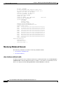
Monitoring Wideband Components 5-1
Monitoring Wideband SIPs 5-2
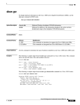
show diag 5-2
Monitoring Wideband SPAs 5-3
show hw-module bay oir 5-3
show diag 5-3
show controllers modular-cable 5-4
Monitoring Wideband Channels 5-6
show interface wideband-cable 5-6
show hw-module bay 5-7
Monitoring RF Channels 5-10
show hw-module bay 5-10
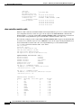
Monitoring Wideband Cable Modems 5-10
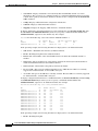
show cable modem wideband 5-11
show cable modem summary 5-11
Troubleshooting Wideband Components 5-13
Troubleshooting Wideband SIPs and Wideband SPAs 5-13
Performing Basic Troubleshooting on a Wideband SIP and Wideband SPA
5-13
Verifying That a Wideband SPA’s Active Gigabit Ethernet Port Is Up 5-14
Verifying That a Wideband SPA Is Correctly Configured for SPA-to-EQAM
Communications 5-16
Verifying That a Wideband SPA Is Able to Communicate with the Edge QAM Device 5-16
Troubleshooting Wideband Channels 5-17
Verifying That a Wideband Channel is Up and Is Transmitting Packets 5-17
Verifying That a Wideband Channel is Configured Correctly 5-18
Troubleshooting Wideband Cable Modems 5-19
Pinging a Wideband Cable Modem 5-19
Verifying That a Wideband-Capable Cable Modem is Registered as a Wideband Modem 5-20
Cisco Cable Wideband Solution Design and Implementation Guide, Release 1.0
OL-10705-02
v
Contents
Verifying Other Information for Wideband Cable Modems
5-21
INDEX
Cisco Cable Wideband Solution Design and Implementation Guide, Release 1.0
vi
OL-10705-02
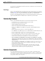
Preface
This preface describes the objectives and organization of this document and explains how to find
additional information on related products and services. This preface contains the following sections:
•
Objectives, page vii
•
Document Revision History, page vii
•
Document Organization, page viii
•
Related Documentation, page viii
•
Conventions, page x
•
Obtaining Documentation, Obtaining Support, and Cisco Security Guidelines, page xi
Objectives
This document describes the Cisco Cable Wideband Solution, Release 1.0. It explains how to design and
implement a cable network with that uses the DOCSIS 3.0 Downstream Channel Bonding feature.
Note
This document describes release-specific functionality for Cisco IOS Releases 12.3(21)BC and
12.3(21a)BC3.
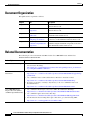
Document Revision History
Table 1 records technical changes to this document. The table shows Cisco IOS software release number
and document revision number for the change, the date of the change, and a brief summary of the change.
Table 1
Document Revision History
Release No.
Revision
Date
Change Summary
12.3(21)BC
OL-10705-01
February 2007
First release
12.3(21a)BC3
OL-10705-02
July 2007
Added information on the Linksys
WCM300-NA, WCM300-EURO,
and WCM300-J modems.
Cisco Cable Wideband Solution Design and Implementation Guide, Release 1.0
OL-10705-02
vii
Preface
Document Organization
Document Organization
This publication is organized as follows:
Chapter
Title
Description
Chapter 1
Solution Overview
Provides an overview of the Cisco Cable Wideband
Solution, Release 1.0.
Chapter 2
Cisco Cable Wideband
Components
Describes the components of the Cisco Cable Wideband
Solution, Release 1.0.
Chapter 3
Cisco Cable Wideband
Architecture
Explains the architecture used for the Cisco Cable
Wideband Solution, Release 1.0.
Chapter 4
Implementing and
Configuring the Solution
Provides implementation and configuration information
for the Cisco Cable Wideband Solution, Release 1.0.
Chapter 5
Monitoring and
Troubleshooting Wideband
Components
Provides an introduction to monitoring and
troubleshooting the wideband components of the Cisco
Cable Wideband Solution, Release 1.0.
Related Documentation
The following is a list of documents and URLs for the Cisco uBR10012 router and the Cisco
Wideband SIP and Wideband SPA:
Related Topic
Document Title
Documentation Roadmap
•
Cisco uBR7200 Series Routers and Cisco uBR10012 Universal Broadband Router
Documentation Roadmap
http://www.cisco.com/en/US/partner/products/hw/cable/ps2209/products_documentatio
n_roadmap09186a0080733a04.html
Cisco uBR10012 Hardware
Installation
•
Cisco uBR10012 Universal Broadband Router SIP and SPA Hardware Installation Guide
http://www.cisco.com/univercd/cc/td/doc/product/cable/ubr10k/ubr10012/sipspa/hwsips
pa/index.htm
Cisco uBR10012 Universal Broadband Router Hardware Installation Guide
http://www.cisco.com/univercd/cc/td/doc/product/cable/ubr10k/ubr10012/hig/
• Regulatory Compliance and Safety Information for the Cisco uBR10012 Universal
Broadband Router
•
http://www.cisco.com/univercd/cc/td/doc/product/cable/ubr10k/ub10rcsi.htm
Cisco uBR10012 Field
Replaceable Units (FRUs)
and Fiber-Optic Maintenance
Cisco uBR10012 Field Replaceable Units (FRUs) Documentation Web Page
http://www.cisco.com/univercd/cc/td/doc/product/cable/ubr10k/ubr10012/frus/index.htm
• Cisco uBR10012 Quick Start Guides Web Page
http://www.cisco.com/univercd/cc/td/doc/product/cable/ubr10k/ubr10012/qsg/index.htm
• For information about cleaning fiber-optic connections, go to the following URL:
•
http://www.cisco.com/warp/public/127/cleanfiber2.html
Cisco Cable Wideband Solution Design and Implementation Guide, Release 1.0
viii
OL-10705-02
Preface
Related Documentation
Related Topic
Cisco uBR10012 Software,
Configuration, and Features
Document Title
•
Cisco uBR10012 Universal Broadband Router SIP and SPA Software Configuration
Guide
http://www.cisco.com/univercd/cc/td/doc/product/cable/ubr10k/ubr10012/sipspa/swsips
pa/index.htm
•
Cisco Cable Wideband Solution Design and Implementation Guide, Release 1.0 (this
document)
http://www.cisco.com/univercd/cc/td/doc/product/cable/ubr10k/ubr10012/wbsolu/index.
htm
Release Notes for Cisco uBR10012 Universal Broadband Router for Cisco IOS Release
12.3 BC
http://www.cisco.com/univercd/cc/td/doc/product/cable/ubr10k/ub10krns/123bcu10.htm
• Cisco uBR10012 Universal Broadband Router Software Configuration Guide
http://www.cisco.com/univercd/cc/td/doc/product/cable/ubr10k/ubr10012/scg/index.htm
• Cisco uBR10012 Router Software Features
http://www.cisco.com/univercd/cc/td/doc/product/cable/ubr10k/ubr10012/ub10ksw/index.htm
• Cisco Cable Modem Termination System Feature Guide
http://www.cisco.com/univercd/cc/td/doc/product/cable/cab_rout/cmtsfg/index.htm
•
Cisco IOS Command
Reference and Related
Information
•
•
•
•
•
For Cisco Wideband SIP and SPA commands, see Chapter 11, “SIP and SPA Commands”
in the Cisco uBR10012 Universal Broadband Router SIP and SPA Software Configuration
Guide.
Cisco Broadband Cable Command Reference Guide
http://www.cisco.com/univercd/cc/td/doc/product/cable/bbccmref/index.htm
Cisco IOS Release 12.3 Web Page
http://www.cisco.com/univercd/cc/td/doc/product/software/ios123/index.htm
Cisco CMTS Error Messages
http://www.cisco.com/univercd/cc/td/doc/product/cable/cab_rout/ubrerrs.htm
Cisco CMTS Universal Broadband Router MIB Specifications Guide
http://www.cisco.com/univercd/cc/td/doc/product/cable/ubr10k/ubr10012/ubrmib5/inde
x.htm
Additional Cable/Broadband
Information Resources
•
Cisco uBR10012 troubleshooting and alerts
http://www.cisco.com/en/US/products/hw/cable/ps2209/tsd_products_support_troublesh
oot_and_alerts.html
Cisco Cable/Broadband Software Center Web page
http://www.cisco.com/public/sw-center/sw-cable.shtml
• Cisco Cable/Broadband Technical Support Web page
http://www.cisco.com/en/US/tech/tk86/tsd_technology_support_category_home.html
• Cisco Multiservice Broadband Cable Guide
http://www.cisco.com/application/pdf/en/us/guest/netsol/ns289/c643/ccmigration_0918
6a008014eeb0.pdf
•
Cisco Cable Wideband Solution Design and Implementation Guide, Release 1.0
OL-10705-02
ix
Preface
Conventions
Conventions
This guide uses the following conventions for command syntax descriptions and textual emphasis:
Table 2
Command Syntax and Emphasis Conventions
Convention
Description
boldface font
Commands and keywords are in boldface.
italic font
Arguments for which you supply values are in italics.
[ ]
Elements in square brackets are optional.
{x | y | z}
Alternative, mutually exclusive, keywords are grouped in braces and
separated by vertical bars.
[x | y | z]
Optional alternative keywords are grouped in brackets and separated by
vertical bars.
string
A nonquoted set of characters. Do not use quotation marks around the string
or the string will include the quotation marks.
screen
font
Terminal sessions and information the system displays are in screen font.
boldface screen
italic screen
font
font
Information you must enter is in boldface screen font.
Arguments for which you supply values are in italic screen font.
^
The symbol ^ represents the key labeled Control—for example, the key
combination ^D in a screen display means hold down the Control key while
you press the D key.
< >
Nonprinting characters, such as passwords, are in angle brackets in contexts
where italics are not available.
[ ]
Default responses to system prompts are in square brackets.
!, #
An exclamation point ( ! ) or a pound sign ( # ) at the beginning of a line of
code indicates a comment line.
Note
This symbol means reader take note. Notes contain helpful suggestions or references to material not
covered in the publication.
Tip
This symbol means the following are useful tips.
Timesaver
Caution
This symbol means the described action saves time. You can save time by performing the action
described in the paragraph.
This symbol means reader be careful. In this situation, you might do something that could result in
equipment damage or loss of data.
Cisco Cable Wideband Solution Design and Implementation Guide, Release 1.0
x
OL-10705-02
Preface
Obtaining Documentation, Obtaining Support, and Cisco Security Guidelines
Obtaining Documentation, Obtaining Support, and Cisco
Security Guidelines
For information on obtaining documentation, providing documentation feedback, obtaining technical
assistance, and Cisco product security guidelines, see the monthly What's New in Cisco Product
Documentation at:
http://www.cisco.com/en/US/docs/general/whatsnew/whatsnew.html
What's New in Cisco Product Documentation also lists all new and revised Cisco technical
documentation.
Cisco Cable Wideband Solution Design and Implementation Guide, Release 1.0
OL-10705-02
xi
Preface
Obtaining Documentation, Obtaining Support, and Cisco Security Guidelines
Cisco Cable Wideband Solution Design and Implementation Guide, Release 1.0
xii
OL-10705-02
C H A P T E R
1
Solution Overview
This chapter provides an overview of the Cisco Cable Wideband Solution, Release 1.0, and contains the
following major topics:
•
Solution Description and Scope, page 1-1
•
Solution Key Features, page 1-3
•
Solution Components, page 1-3
In this document, the terms wideband channel, bonded channel, and bonding group have the same
meaning: a logical grouping of one or more physical radio frequency (RF) channels over which
MPEG-TS packets are carried.
Solution Description and Scope
Cisco IOS Release 12.3(21)BC and 12.3(21a)BC3 support the DOCSIS 3.0 Downstream Channel
Bonding feature, which is the key feature of the Cisco Cable Wideband Solution, Release 1.0.
In the Cisco Cable Wideband Solution, Release 1.0, the DOCSIS 3.0 Downstream Channel Bonding
feature supports downstream wideband channels consisting of multiple bonded RF channels. The
solution provides wideband data services over existing hybrid fiber coax (HFC) networks. With
wideband data services, multiple RF channels are aggregated into a single logical wideband
channel (bonding group) that delivers higher bandwidth to the wideband cable modem than was
previously possible with DOCSIS 2.0 technology. This aggregation of RF channels is referred to as
“channel bonding.”
The maximum bandwidth supported depends on the number of RF channels that can be aggregated into
a wideband channel. For example:
•
The Linksys WCM300-NA wideband cable modem supports downstream throughput of up to
approximately 292 Mbps (with a wideband channel consisting of eight RF channels at 6 MHz and
256 QAM).
•
The Scientific Atlanta DPC2505 wideband cable modem supports downstream throughput of up to
approximately 74 Mbps (with a wideband channel consisting two RF channels at 6 MHz and
256 QAM).
The Cisco Cable Wideband Solution, Release 1.0, can be deployed in parallel with DOCSIS 1.X/2.0
technology. The CMTS supports DOCSIS 1.X/ 2.0 modems on non-wideband ports while wideband
cable modems deliver higher-speed throughput on the wideband ports.
Cisco Cable Wideband Solution Design and Implementation Guide, Release 1.0
OL-10705-02
1-1
Chapter 1
Solution Overview
Solution Description and Scope
Architecture and Scope
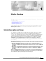
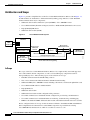
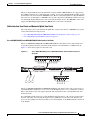
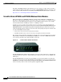
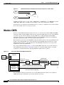
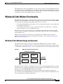
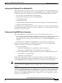
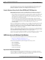
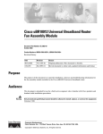
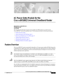
Figure 1-1 presents a simplified view of the Cisco Cable Wideband Solution, Release 1.0. In Figure 1-1,
two RF channels are bonded into a wideband channel (bonding group). The Cisco Cable Wideband
Solution includes these major components:
•
Wideband cable modem termination system (WCMTS)—Cisco uBR10012 router
•
Cisco Wideband SPA (Shared Port Adapter) and Cisco Wideband SIP (SPA Interface Processor)
•
Edge QAM (EQAM) device
•
Wideband cable modem (WCM)
Figure 1-1
Cisco Wideband Cable System
uBR10012
WCMTS
WAN
WAN
Wideband SIP
Wideband SPA GE
Downstream
wideband
channel
MC5X20
cable interface
line card
Downstream
wideband channel
GE
switch
Edge QAM
device
RF
Wideband
cable modem
Downstream RF channel for MAC management
and signaling messages
191347
Regional
cable
headend
Traditional DOCSIS upstream channel for
return data traffic and signaling
In Scope
The scope of the Cisco Cable Wideband Solution, Release 1.0, comprises fully tested and supported
Cisco and Scientific Atlanta components, as well as selected third-party components tested for
interoperability by Cisco. The following aspects of the solution are in scope:
•
DOCSIS 3.0 Downstream Channel Bonding software
•
One or more downstream wideband channels with RF channel bonding
•
Wideband CMTS (Cisco uBR10012 router) including cable interface and network uplink line cards
•
Cisco Wideband SIP and Cisco Wideband SPA
•
Edge QAM device
•
Wideband cable modem
•
Wideband-related cable modem configuration file parameters
•
Cisco IOS command set for wideband-channel configuration, provisioning, and maintenance
•
Cisco IOS command set for wideband hardware monitoring, troubleshooting, and debugging
•
MIBs for the wideband CMTS, wideband cable modem, and wideband channel and service statistics
Device configuration that is in scope for this document is limited to the Wideband SIP and Wideband
SPA. Comprehensive documentation for other CMTS components is provided in the existing
Cisco uBR10012 documentation set, which is accessible at www.cisco.com.
Cisco Cable Wideband Solution Design and Implementation Guide, Release 1.0
1-2
OL-10705-02
Chapter 1
Solution Overview
Solution Key Features
For information on edge QAM device installation and software configuration, refer to the vendor’s edge
QAM device documentation.
Out of Scope
The Cisco Cable Wideband Solution-related information in this document pertains to the components
listed in “In Scope” section above. Not included in the scope of the Cisco Cable Wideband Solution are
the hardware and software components that make up the remainder of the cable data network.
For the Cisco Cable Wideband Solution, Release 1.0, cable network management tools and operations
support system (OSS) facilities for wideband cable are outside the scope of the solution.
Solution Key Features
The Cisco Cable Wideband Solution, Release 1.0, provides the following key features:
•
Pre-DOCSIS 3.0 version of wideband cable that uses packet bonding
•
Channel-bonded wideband downstream channels
•
Traditional DOCSIS 2.0 upstream channels
•
Solution can be deployed in parallel with DOCSIS 1.X/2.0 technology.
•
Existing Cisco uBR10012 router (CMTS) can be upgraded to wideband CMTS with add-on
components.
•
Modular CMTS architecture makes use of external edge QAM devices.
•
Cisco uBR10012 router (CMTS) supports up to two Wideband SPAs in a Wideband SIP jacket card.
•
Each Cisco Wideband SPA can support up to 24 downstream RF channels.
•
Each Cisco Wideband SPA can support up 12 logical wideband channels (bonding groups).
•
Cisco Wideband CMTS and line cards have built-in redundancy and resiliency features.
•
Scientific Atlanta and third-party edge QAM devices are tested for interoperability.
•
Linksys WCM300-NA, WCM300-EURO (for EuroDOCSIS), and WCM300-JP (for J-DOCSIS)
wideband cable modems support the receiving of up to eight RF channels, which can be bonded into
wideband channels. One traditional DOCSIS downstream channel is used for MAC management and
signalling messages.
•
Linksys WCM300-NA, WCM300-EURO, and WCM300-JP wideband cable modems support one
primary bonded (wideband) channel for unicast and multicast traffic and up to two secondary
bonded channels for multicast traffic.
•
Scientific Atlanta DPC2505 and EPC2505 wideband cable modems support one bonded
downstream channel consisting of two RF channels, and support one traditional DOCSIS
downstream channel for MAC management and signalling messages.
Solution Components
Cisco Cable Wideband Solution, Release 1.0, consists of Cisco, Linksys, and Scientific Atlanta
components that are tested, documented, and fully supported by Cisco, Linksys, or Scientific Atlanta.
Also, third-party equipment, although not fully supported by Cisco, has been selected and tested for
interoperability with the solution components.
Cisco Cable Wideband Solution Design and Implementation Guide, Release 1.0
OL-10705-02
1-3
Chapter 1
Solution Overview
Solution Components
Cisco, Linksys, and Scientific Atlanta Equipment
For the Cisco Cable Wideband Solution, Release 1.0, the following Cisco, Linksys, and Scientific
Atlanta equipment have been tested in the context of the solution.
•
Cisco uBR10012 universal broadband router with PRE2 processor modules and these components:
– Cisco SPA Interface Processor (SIP) for the 1-Gbps Wideband SPA—referred to in this
document as the Cisco Wideband SIP or Wideband SIP
– Cisco 1-Gbps Wideband Shared Port Adapter (SPA)—referred to in this document as the Cisco
Wideband SPA or Wideband SPA
– Cisco uBR10-MC5X20S/U/H and uBR10-MC5X20U-D cable interface line cards
•
Edge QAM device
– Scientific Atlanta Continuum DVP XDQA24 EQAM device
•
Wideband cable modem
– Linksys WCM300-NA, WCM300-EURO, and WCM300-JP wideband cable modems
– Scientific Atlanta DPC2505 and EPC2505 wideband cable modems
Third-Party Equipment
For the Cisco Cable Wideband Solution, Release 1.0, Table 1-1 lists the third-party component, vendor,
and the basic functionality each component provides.
Table 1-1
Component Partners and Basic Functionality
Component and Vendor
Basic Functionality
Harmonic NSG 9116
Edge QAM device
www.harmonicinc.com
Harmonic NSG 9000
Edge QAM device
www.harmonicinc.com
Vecima Networks VistaLynx VL1000
Edge QAM device
www.vecimanetworks.com
Cisco Cable Wideband Solution Design and Implementation Guide, Release 1.0
1-4
OL-10705-02
C H A P T E R
2
Cisco Cable Wideband Components
This chapter describes the components of the Cisco Cable Wideband Solution, Release 1.0, and contains
the following topics:
•
Base CMTS Components, page 2-1
•
Wideband CMTS Components, page 2-8
•
Wideband Cable Modems, page 2-14
•
Wideband CMTS Redundancy and Resiliency, page 2-18
•
Where to Find Information on Solution Hardware Components, page 2-21
Cisco Cable Wideband Add-on Components
The Cisco uBR10012 router can be used as a DOCSIS 1.x/2.0 CMTS and, in this mode, does not need
any wideband components. Wideband cable components can be added to the Cisco uBR10012 base
system so that it can be used as a wideband CMTS. As demand for wideband cable grows, this ability to
increase capacity by adding wideband components to an existing uBR10012 base system is less
expensive than adding additional chassis. This Cisco Cable Wideband Solution add-on strategy reduces
both capital expenditure and operational expenses.
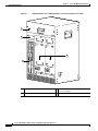
Base CMTS Components
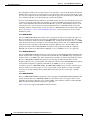
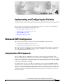
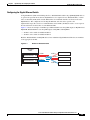
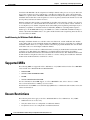
For the Cisco Cable Wideband Solution, Release 1.0, the Cisco uBR10012 router (Figure 2-1 and
Figure 2-2) is the wideband cable modem termination system (WCMTS). The CMTS may be located at
the cable headend or at a distribution hub. The Cisco Cable Wideband Solution uses the modular
CMTS (M-CMTS) architecture with one or more external edge QAM (EQAM) devices.
Cisco Cable Wideband Solution Design and Implementation Guide, Release 1.0
OL-10705-02
2-1
Chapter 2
Cisco Cable Wideband Components
Base CMTS Components
Figure 2-1
Wideband CMTS: Cisco uBR10012 Router—Front View without Front Cover
1
2
CISCO
10000
POWER
MISWIR
E
FAULT
CISCO
10000
C
O
N
S
O
LE
C
O
N
S
O
LE
AU
X
POWER
MISWIR
E
FAULT
AU
X
1
OT
0
OT
A
C
TIV
IT
Y
E
TH
E
LIN RN
K ET
SL
SL
1
OT
0
OT
SL
SL
A
C
TIV
IT
E
TH Y
E
LIN RN
E
T
K
4
3
ALARMS
ALARMS
A
C
O
A
C
O
C
R
IT
IC
C
A
M
R
L
A
IT
IC
JO
R
IN
O
R
TA
TU
S
FA
IL
L
A
JO
R
M
IN
O
R
S
TA
TU
S
FA
88670
IL
PERFORMANCE ROUTING ENGINE
S
A
M
PERFORMANCE ROUTING ENGINE
M
1
Fan assembly module
3
Two Performance Routing Engine 2 (PRE2)
processor modules
2
LCD module
4
Two DC Power Entry Modules (DC PEMs)
Cisco Cable Wideband Solution Design and Implementation Guide, Release 1.0
2-2
OL-10705-02
Chapter 2
Cisco Cable Wideband Components
Base CMTS Components
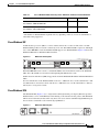
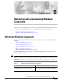
Figure 2-2
PO
W
ER
ST
AT
US
PO
W
ER
ST
AT
US
PO
W
ER
ST
AT
US
M
AI
NT
PO
W
ER
ST
AT
US
M
AI
NT
PO
W
ER
ST
AT
US
M
AI
NT
uBR10-MC5x20S-D
M
AI
NT
uBR10-MC5x20S-D
M
AI
NT
uBR10-MC5x20S-D
M
AI
NT
uBR10-MC5x20S-D
PO
W
ER
ST
AT
US
uBR10-MC5x20S-D
M
AI
NT
uBR10-MC5x20S-D
PO
W
ER
ST
AT
US
uBR10-MC5x20S-D
M
AI
NT
uBR10-MC5x20S-D
PO
W
ER
ST
AT
US
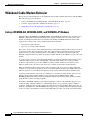
Wideband CMTS: Cisco uBR10012 Router —Rear View
1
US0
US1
US0
US1
US0
US3
US2
US1
US0
US3
US2
US1
US0
US4
US3
US2
US1
US0
US4
US3
US2
US4
US5
US6
US4
US5
US7
US6
US5
US8
US7
US6
US1
US2
US3
US4
US0
US1
US2
US1
US3
US2
US4
US3
US6
US5
US8
US7
US6
US5
US9
US8
US7
US6
US5
US9
US8
US9
US4
US9
US6
US7
US8
CISCO
10000
CISCO
uBR1000
0
0
US7
US8
US9
CISCO
10000
IL
FA
US7
NK
LI
US6
US8
NK
LI
US7
US9
IL
FA
US8
US5
IL
FA
US9
US2
US3
US4
US5
US9
L
A/
1
US10
US10
US12
US11
US10
US13
US12
US11
US10
US13
US12
US11
US10
US14
US13
US12
US11
US10
US14
US14
US13
US12
US11
US14
US13
US12
US14
US13
L
US15
0
US15
US16
A/
US11
US10
US11
US10
US12
US11
US13
US12
US14
US13
US17
US16
US15
US18
US17
US16
US15
US18
US17
US16
US15
US19
US18
US17
US16
US15
US19
US18
US17
US16
US18
US17
US16
US15
US19
US18
US17
US16
US19
US18
US17
US19
US18
US19
US14
SPA-24XDS-SFP
US19
US14
US15
US
AT
ST
US19
CISCO
10000
RF
DS2
DS1
DS0
DS3
DS2
DS1
DS0
DS3
DS2
DS1
DS4
DS3
DS2
DS4
DS3
RF
DS4
RF
RF
RF
RF
RF
RF
RF
RF
RF
RF
DS1
DS0
DS2
DS1
DS0
DS3
DS2
DS1
DS0
DS4
DS3
DS2
DS1
DS4
DS3
DS2
DS4
DS3
RF
RF
RF
RF
DS4
CISCO
10000
DS0
RF
RF
RF
RF
RF
RF
RF
RF
RF
RF
RF
RF
RF
1
RF
L
RF
RF
A/
RF
RF
NK
LI
RF
NK
LI
RF
0
DS1
DS0
IL
FA
IL
FA
DS0
RF
RF
RF
A/
L
DS4
RF
1
SPA-24XDS-SFP
US
AT
ST
153650
OT
SL ID
SPA INTERFACE PROCESSOR CARD
P/N UBR10-2XDS-SIP
4
3
2
1
Two Timing, Communication, and Control
Plus (TCC+) cards
3
2
One Wideband SIP with two Wideband SPAs 4
Four Half-Height Gigabit Ethernet line cards
Eight uBR10-MC5X20S/U/H or
uBR10-MC5X20U-D cable interface line
cards
Figure 2-2 shows a fully loaded uBR10012 chassis. The minimum number of components needed for
base CMTS or wideband CMTS operation is less than shown in Figure 2-2. For information on minimum
and recommended hardware requirements, see the “Base CMTS Component Requirements” section on
page 2-4 and the “Wideband CMTS Components” section on page 2-8.
Cisco Cable Wideband Solution Design and Implementation Guide, Release 1.0
OL-10705-02
2-3
Chapter 2
Cisco Cable Wideband Components
Base CMTS Components
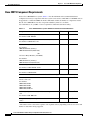
Base CMTS Component Requirements
For the Cisco uBR10012 base system, Table 2-1 lists the minimum and recommended hardware
configurations for major components. The base system can be used as a DOCSIS 1.x/2.0 CMTS and can
be upgraded to a wideband CMTS. In the Recommended column, the number of components ensures
that the Cisco uBR10012 router has component redundancy where it is available.
Cisco IOS Release 12.3(21)BC or later is required for wideband cable functionality.
Table 2-1
Cisco uBR10012 Base System: Minimum and Recommended Hardware
Component
Minimum
Recommended
Performance Routing Engine 2 (PRE2)
1
2
1
2
1
2
1
1
1
1
Part number: ESR-PRE2/R
Timing, Communication, and Control Plus card (TCC+)
Part number: UBR10-TCC+-T1
DC Power Entry Modules (DC PEMs)
Part number:
UBR10-PWR-DC (Primary)
UBR10-PWR-DC\R (Redundant)
OR
AC Power Entry Modules (AC PEMs)
Part number:
UBR10-PWR-AC (Primary)
UBR10-PWR-AC\R (Redundant)
Fan assembly module
Part number: UBR-10-FAN-ASSY
LCD module
Part number: UBR10-DSPL
Cable Interface Line Cards and Network Uplink Line Cards
uBR10-MC5X20S/U/H or uBR10-MC5X20U-D cable
interface line card
1
At least 2*
1
At least 2*
1
Varies*
Part number:
uBR10-MC5X20S
uBR10-MC5X20U
uBR10-MC5X20H
uBR10-MC5X20U-D
Half-Height Gigabit Ethernet (HHGE) network uplink line
card
Part number: ESR-HH-1GE
Slot splitter card (One is required for each two HHGE line
cards.)
* The number of line cards and slot splitter cards required will vary depending on the set of services and
number of subscribers being supported.
Cisco Cable Wideband Solution Design and Implementation Guide, Release 1.0
2-4
OL-10705-02
Chapter 2
Cisco Cable Wideband Components
Base CMTS Components
The Cisco Gigabit Ethernet network uplink line card (part number UBR10-1GE) is also supported as a
base CMTS component. It is a full-height line card that, for use with a Wideband SIP and SPA, should
be installed in slot 3/0 or 4/0 of the uBR10012 router. However, the (full-height) Cisco Gigabit Ethernet
line card is not recommended as a uBR10012 base system component for Wideband Cable because only
two full-height Gigabit Ethernet line cards can be installed in the chassis. The uBR10012 chassis will
support four Half-Height Gigabit Ethernet (HHGE) line cards in slots 3/0 and 4/0.
Cable Interface Line Cards and Network Uplink Line Cards
The cable interface line cards and network uplink line cards used on the Cisco uBR10012 base system
are described in the following sections:
•
Cisco uBR-MC5X20S/U/H and uBR10-MC5X20U-D Cable Interface Line Cards, page 2-5
•
Cisco Half-Height Gigabit Ethernet Line Card, page 2-7
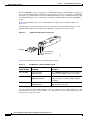
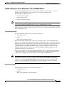
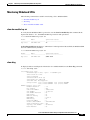
Cisco uBR-MC5X20S/U/H and uBR10-MC5X20U-D Cable Interface Line Cards
The Cisco uBR10-MC5X20S/U/H and uBR10-MC5X20U-D cable interface line cards transmit and
receive RF signals between the subscriber and the headend over hybrid fiber/coax (HFC) network.
Figure 2-3 shows the faceplate for these line cards.
US9
US8
US7
US6
US5
US4
US3
US1
US2
US0
US5
Cisco uBR10-MC5X20S/U/H or uBR10-MC5X20U-D Cable Interface Line Card
Faceplate
US4
Figure 2-3
72321
DS4RF
DS3RF
DS2RF
DS1RF
DS0RF
US19
US18
US17
US16
US15
US14
US13
US12
US11
US10
US9
US8
US7
US6
US3
US2
US1
DS4RF
DS3RF
DS2RF
DS1RF
DS0RF
PO
W
ER
ST
AT
US
MA
IN
T
US0
MA
IN
T
PO
WE
R
STA
TU
S
uBR10-MC5x20S-D
The Cisco uBR-MC5X20S/U/H and uBR10-MC5X20U-D cable interface line cards can be used for a
standard DOCSIS 1.X/2.0 service or for a Cisco Cable Wideband service or for a combination of the two.
These cable interface line cards support upstream and downstream traffic over DOCSIS-based cable
modem networks.
For a DOCSIS 1.X/2.0 and for Cisco Cable Wideband Solution, Release 1.0, operation, upstream data
from the subscriber comes through the upstream ports (US0-US19) on the line cards. The line card
processes and configures the data and sends it across the backplane to the WAN/backhaul card and out
to the Internet.
Cisco Cable Wideband Solution Design and Implementation Guide, Release 1.0
OL-10705-02
2-5
Chapter 2
Cisco Cable Wideband Components
Base CMTS Components
For a DOCSIS 1.X/2.0 system, downstream data to the subscriber, comes from the Internet through the
WAN/backhaul card, and across the backplane to the cable interface line card. The cable interface card
processes and configures the data and sends it out through the appropriate downstream port (DS0 - DS4)
to be combined with the rest of the downstream signals in the headend.
For Cisco Cable Wideband Solution, Release 1.0 bonded channel operation, the cable interface line cards
are used for upstream return traffic and signalling, for downstream MAC management and signaling
traffic, and for DOCSIS 3.0 Downstream Channel Bonding operations. With wideband, the use of the
cable interface line card’s downstream channel is different than for a DOCSIS 1.X/2.0 system. The
wideband channel’s downstream data traffic uses the Cisco Wideband SPA and an external edge QAM
device. See Chapter 3, “Cisco Cable Wideband Architecture” for more information on Cisco Cable
Wideband systems.
Cisco uBR10-MC5X20S
The Cisco uBR10-MC5X20S cable interface line card supports downstream and upstream traffic over
Data-over-Cable Service Interface Specification (DOCSIS)-based cable modem networks. The card
supports downstream channels in the 70 to 860 MHz range, and upstream channels in the 5 to 42 MHz
range. Each downstream port includes an onboard integrated upconverter. The Cisco uBR10-MC5X20S
cable interface line card supports Annex B radio frequency (RF) data rates, channel widths, and
modulation schemes and has DOCSIS MAC management and spectrum management capabilities.
DOCSIS 2.0, Asynchronous Time Division Multiple Access (A-TDMA) rates are also supported.
Cisco uBR10-MC5X20U and H
The Cisco uBR10-MC5X20U/H cable interface line card supports both DOCSIS and EuroDOCSIS cable
modem networks. The card supports downstream channels in the 70 to 860 MHz range, and upstream
channels in the 5 to 65 MHz range. Each downstream port includes an onboard integrated upconverter.
The Cisco uBR10-MC5X20U/H cable interface line card supports Annex B and Annex A radio
frequency (RF) data rates, channel widths, and modulation schemes and has DOCSIS MAC management
and spectrum management capabilities. DOCSIS 2.0, A-TDMA rates are also supported.
Compared to the Cisco uBR10-MC5X20U, the uBR10-MC5X20H increases the line card CPU speed,
memory, and flash, allowing support of Voice over IP (VoIP) at much higher call loads and a higher
percentage of modems running advanced DOCSIS features that typically consume line card CPU
resources.
Cisco uBR10-MC5X20U-D
The Cisco uBR10-MC5X20U-D cable interface line card supports both DOCSIS and EuroDOCSIS cable
modem networks. The Cisco uBR10-MC5X20U-D cable interface line card supports Annex A and
Annex B radio frequency (RF) data rates, channel widths, and modulation schemes and has DOCSIS
MAC management and spectrum management capabilities.
Table 2-2 shows the supported DOCSIS modulation schemes.
Cisco Cable Wideband Solution Design and Implementation Guide, Release 1.0
2-6
OL-10705-02
Chapter 2
Cisco Cable Wideband Components
Base CMTS Components
Table 2-2
Supported DOCSIS and EuroDOCSIS Modulation Schemes
Cable Interface Line Card
Downstream Modulation
Upstream Modulation
1
Cisco uBR10-MC5X20S
64-QAM , 256-QAM
QPSK2, 8-, 16-, 32-, 64-QAM
Cisco uBR10-MC5X20U
64-QAM, 256-QAM
QPSK, 8-, 16-, 32-, 64-QAM
Cisco uBR10-MC5X20H
64-QAM, 256-QAM
QPSK, 8-, 16-, 32-, 64-QAM
Cisco uBR10-MC5X20U-D
64-QAM, 256-QAM
QPSK, 8-, 16-, 32-, 64-QAM
1. QAM = Quadrature Amplitude Modulation
2. QPSK = Quadrature Phase Shift Keying
The Cisco uBR-MC5X20S/U/H and uBR10-MC5X20U-D line cards use space-saving dense connectors.
Each line card supports online insertion and removal (OIR) and can be added or removed without
powering off the chassis. For more information on these cable interface line cards, refer to the document
Cisco uBR10-MC5X20S/U/H Cable Interface Line Card (hardware installation).
Cisco Half-Height Gigabit Ethernet Line Card
The Cisco half-height Gigabit Ethernet (HHGE) line card is a single-port Gigabit Ethernet (GE) line card
that provides a trunk uplink to devices such as backbone routers, as well as connections to content
servers and IP telephony gateways. The GE line card provides the Cisco uBR10012 router with an IEEE
802.3z compliant Ethernet interface that can run up to 1 Gbps in full duplex mode. Figure 2-4 shows the
faceplate for the HHGE line card.
Figure 2-4
Half-Height Gigabit Ethernet Line Card Faceplate
3
L
K
I
FA
LIN
5
4
RX
TX
0
TX
RX
GIGABIT ETHERNET
135335
CISCO
10000
2
6
1
1
1
Ejector Levers
4
SFP Gigabit Ethernet Interface Converter
2
FAIL LED (yellow)
5
Link Status (green)
3
Receive Packet (green)
6
Transmit Packet (green)
The Cisco uBR10012 router supports up to four HHGE line cards to allow connectivity to multiple
destinations, and to provide network layer redundancy. The HHGE line card requires a slot splitter card
that should be installed in either slot 4/0 or slot 3/0 on the uBR10012 router. Each slot splitter can hold
two HHGE line cards. Therefore, the uBR10012 base system with two slot splitters supports up to four
HHGE lines cards.
The HHGE line card uses a small form-factor pluggable (SFP) gigabit interface converter (GBIC)
module that supports a variety of Gigabit Ethernet interface types (SX LX/LH, and ZX), which you can
change or upgrade at any time.
Cisco Cable Wideband Solution Design and Implementation Guide, Release 1.0
OL-10705-02
2-7
Chapter 2
Cisco Cable Wideband Components
Wideband CMTS Components
SFP Module for HHGE Line Cards
Mylar tab
Bale clasp
76415
Figure 2-5
The following SFP modules are supported by the HHGE line card:
•
1000BASE-SX SFP—The SFP-GE-S, 1000BASE-SX SFP operates on ordinary multimode fiber
optic link spans of up to 550 meters in length.
•
1000BASE-LX/LH SFP—The SFP-GE-L, 1000BASE-LX/LH SFP operates on ordinary
single-mode fiber optic link spans of up to 10,000 meters in length.
•
1000BASE-ZX SFP—The GLC-ZX-SM, 1000BASE-ZX SFP operates on ordinary single-mode
fiber optic link spans of up to 70 kilometers (km) in length. Link spans of up to 100 km are possible
using premium single-mode fiber or dispersion-shifted single-mode fiber. The precise link span
length depends on multiple factors such as fiber quality, number of splices, and connectors.
The HHGE line card supports online insertion and removal (OIR) and can be added or removed without
powering off the chassis. For more information on the HHGE line card, refer to the Cisco uBR10012
Universal Broadband Router Hardware Installation Guide.
Wideband CMTS Components
A Cisco uBR10012 base system can be upgraded to a wideband CMTS by adding these components:
•
Wideband SIP and Wideband SPA, page 2-8
•
External Edge QAM Device, page 2-11
For information on the wideband CMTS functionality, see the “Modular CMTS” section on page 3-4.
Wideband SIP and Wideband SPA
The Wideband SIP and Wideband SPA needed for wideband cable can be added to the base Cisco
uBR10012 system when they are required. For the Wideband SIP and Wideband SPA, Table 2-3 lists the
minimum and recommended hardware configurations.
Cisco Cable Wideband Solution Design and Implementation Guide, Release 1.0
2-8
OL-10705-02
Chapter 2
Cisco Cable Wideband Components
Wideband CMTS Components
Table 2-3
Cisco uBR10012 Wideband Components: Minimum and Recommended Hardware
Component
Minimum
Recommended
Wideband SIP (SPA Interface Processor)
1
1
1
Varies*
Part Number: UBR10-2XDS-SIP
Wideband SPA (Shared Port Adapter)
Part Number: SPA-24XDS-SFP
* The number of Wideband SPAs required will vary depending on the set of services and number of
subscribers being supported.
Cisco Wideband SIP
A SPA interface processor (SIP) is a carrier card that inserts into a router slot like a line card. The
Wideband SIP provides no network connectivity on its own. The Wideband SIP occupies two full height
slots on the uBR10012 router. Each Wideband SIP supports two Wideband SPAs. Figure 2-6 shows the
Wideband SIP with two Wideband SPAs installed.
Figure 2-6
Wideband SIP Faceplate
0
IL
FA
1
SPA INTERFACE PROCESSOR CARD
P/N UBR10-2XDS-SIP
S
S
U
AT
ST
U
AT
ST
A/L
A/L
1
SPA-24XDS-SFP
0
A/L
1
A/L
OT
SL ID
SPA-24XDS-SFP
153649
CISCO
uBR10000
0
When the uBR1012 router is used as a wideband CMTS, slots 1/0 and 2/0 are used for the Wideband
SIPs. Slots 3/0 and 4/0 are reserved for half-height Gigabit Ethernet line cards.
Online insertion and removal (OIR) is supported for both the Wideband SIP and the individual Wideband
SPAs.
For more information on the Wideband SIP, see the Cisco uBR10012 Universal Broadband Router SIP
and SPA Hardware Installation Guide and the Cisco uBR10012 Universal Broadband Router SIP and
SPA Software Configuration Guide.
Cisco Wideband SPA
The Wideband SPA (Figure 2-7) is a single-wide, half-height shared port adapter (SPA) that provides
Wideband Protocol for a DOCSIS Network formatting to the downstream data packets. The Wideband
SPA is used for downstream data traffic only. It has one active and one redundant Gigabit Ethernet port
that are used to send traffic to the external edge QAM device.
Figure 2-7
Wideband SPA Faceplate
0
A/L
1
A/L
SPA-24XDS-SFP
153648
S
U
AT
ST
Cisco Cable Wideband Solution Design and Implementation Guide, Release 1.0
OL-10705-02
2-9
Chapter 2
Cisco Cable Wideband Components
Wideband CMTS Components
The Cisco uBR10012 router can support up to two Wideband SPAs. Each Wideband SPA can support up
to 12 logical wideband channels (bonding groups). Depending on how it is configured, each Wideband
SPA allows up to 24 RF channels. Each logical wideband channel consists of multiple RF channels. The
Cisco IOS CLI includes a set of commands to configure the Wideband SPA on the Cisco uBR10012
router.
The two Gigabit Ethernet ports on the Wideband SPA use small form-factor (SFP) modules (see
Figure 2-8).
An SFP module is an input/output (I/O) device that plugs into the Gigabit Ethernet SFP ports on the
Wideband SPA, linking the port with an edge QAM device through a fiber-optic network.
SFP Module (Fiber-Optic LC Connector)
G
1 L
C
L 21 -S
N
S # CF X
/N 50 R -M
: 7 10 M
O / 4 C
H 01 0 la
1 .1 s
2
3 0 s
3
4
5
6 0
3
-1
3
Figure 2-8
Receive optical bore
Transmit optical bore
Bail clasp
130927
Dust plug
Table 2-4 lists the SFP modules that the Wideband SPA supports.
Table 2-4
SFP Modules for the Cisco Wideband SPA
SFP Module
Product Number
SFP Module
Description
GLC-SX-MM
Short wavelength
(1000BASE-SX)
Cisco 1000BASE-SX SFP transceiver module for
multimode fiber (MMF), 850-nm wavelength
GLC-LH-SM
Long wavelength/long haul
(1000BASE-LX/LH)
Cisco 1000BASE-LX/LH SFP transceiver
module for single-mode fiber (SMF), 1300-nm
wavelength
GLC-ZX-SM
Extended distance
(1000BASE-ZX)
Cisco 1000BASE-ZX SFP transceiver module for
SMF, 1550-nm wavelength
For more information on the Wideband SPA, see the Cisco uBR10012 Universal Broadband Router SIP
and SPA Hardware Installation Guide and the Cisco uBR10012 Universal Broadband Router SIP and
SPA Software Configuration Guide.
Cisco Cable Wideband Solution Design and Implementation Guide, Release 1.0
2-10
OL-10705-02
Chapter 2
Cisco Cable Wideband Components
Wideband CMTS Components
External Edge QAM Device
The Cisco wideband CMTS uses one or more external edge QAM (EQAM) devices. The EQAM device
is a network element in a separate chassis from the CMTS. The EQAM device has two or more Gigabit
Ethernet input interfaces that connect to a Wideband SPA. For output, the EQAM device has multiple
QAM modulators and RF upconverters that connect to a hybrid fiber coaxial (HFC) network. The edge
QAM device accepts MPEG over IP on its Gigabit Ethernet interfaces and routes the services to its QAM
RF outputs.
The following edge QAM devices have been tested for interoperability with other Cisco Cable Wideband
Solution, Release 1.0, components:
•
Scientific Atlanta Continuum DVP XDQA24, page 2-12
•
Harmonic NSG 9116, page 2-12
•
Harmonic NSG 9000, page 2-12
•
Vecima Networks VistaLynx VL1000, page 2-13
Table 2-5 lists the number of output QAM channels supported by each edge QAM device.
Table 2-5
EQAM Devices: Number of Output QAM Channels Supported
EQAM Device
Number of Output QAM Channels Supported
Scientific Atlanta Continuum DVP XDQA24
scalable up to 24 QAM channels
Harmonic NSG 9116
16 QAM channels
Harmonic NSG 9000
scalable up to 72 QAM channels
Vecima Networks VistaLynx VL1000
scalable up to 24 QAM channels
Number of EQAM Devices Required
Each logical RF channel defined on the Wideband SPA must have one corresponding output QAM
channel on an EQAM device. The number of EQAM devices required is determined by two factors:
•
The number of logical RF channels in use on the Wideband SPAs in the CMTS. Each Wideband SPA
supports up to 24 logical RF channels depending on how it is configured.
– For annex A and 256 QAM, each Wideband SPA supports 18 RF channels.
– For all other cases, each Wideband SPA supports 24 RF channels.
•
The number of output QAM channels on the EQAM device. See Table 2-5.
As an example, if a Cisco uBR10012 router (CMTS) contains two Wideband SPAs and each Wideband
SPA is configured for 18 RF channels, the total number of RF channels that are in use is 36. Therefore,
36 output QAM channels are required on the EQAM devices. This requirement for output QAM channels
could be met by deploying, for example, two DVP XDQA24 EQAMs (with 48 total QAMs) or three NSG
9116 EQAMs (with 48 total QAMs).
If more than two EQAM devices are required for two Wideband SPAs, a Gigabit Ethernet switch is
needed to connect the SPAs to the EQAM devices.
Cisco Cable Wideband Solution Design and Implementation Guide, Release 1.0
OL-10705-02
2-11
Chapter 2
Cisco Cable Wideband Components
Wideband CMTS Components
Scientific Atlanta Continuum DVP XDQA24
The Scientific Atlanta Continuum DVP eXtra Dense QAM Array 24 (XDQA24) is one of the edge QAM
devices that has been tested for interoperability with other solution components. The Continuum DVP
XDQA24 has two redundant Gigabit Ethernet input interfaces that use small form-factor
pluggable (SFP) modules for fiber-optic and copper links. It has 24 output QAM channels (12 outputs,
each with two adjacent QAM channels). The Continuum DVP XDQA24 software is customized to
accommodate the requirements of the Cisco Cable Wideband Solution.
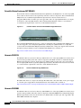
Figure 2-9
Scientific Atlanta Continuum DVP XDQA24 Edge QAM Device
The Continuum DVP XDQA24 chassis is a single rack unit high. The Continuum DVP XDQA24 uses
uses hot-swappable, auto-configurable QAM cards containing two QAM channels on a single RF
converter. The Continuum DVP XDQA24 has fully redundant AC or DC power supplies. More detailed
information and part numbers for the Continuum DVP XDQA24 are available at:
http://www.scientificatlanta.com/customers/source/7005301.pdf
Harmonic NSG 9116
The Harmonic Narrowcast Services Gateway (NSG) 9116 is one of the edge QAM devices that has been
tested for interoperability with other solution components. The NSG 9116 has two redundant Gigabit
Ethernet input interfaces that use small form factor (SFP) modules for fiber-optic and copper links. It
has 16 output QAM channels (eight dual QAM output channels). The NSG 9116 software is customized
to accommodate the requirements of the Cisco Cable Wideband Solution.
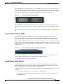
Figure 2-10
Harmonic NSG 9116 Edge QAM Device
The NSG 9116 chassis is a single rack unit high. The NSG 9116 comes with either an AC power supply
or –48 VDC power supply. More detailed information on the NSG 9116 is available at:
http://www.harmonicinc.com/stageone/files/harmonic/collateral/NSG%5Fv03%2D09%5FRS%2Epdf
Harmonic NSG 9000
The Harmonic Narrowcast Services Gateway (NSG) 9000 is one of the edge QAM devices that has been
tested for interoperability with other solution components. The NSG 9000 has three independent Gigabit
Ethernet input interfaces that use small form factor (SFP) modules for fiber-optic and copper links. The
NSG 9000 is DOCSIS 3.0-compliant.
Cisco Cable Wideband Solution Design and Implementation Guide, Release 1.0
2-12
OL-10705-02
Chapter 2
Cisco Cable Wideband Components
Wideband CMTS Components
The NSG 9000 provides scalable support up to 72 QAM RF outputs. The chassis is fitted with a passive
backplane, while all the processing and modulation functions are performed on retrievable modules. The
chassis has nine QAM RF module slots. Each hot-swappable QAM module has two RF ports, and each
port is capable of supporting up to 4 adjacent QAM channels (3 channels in Annex A).
Figure 2-11
Harmonic NSG 9000 Edge QAM Device
The NSG 9000 is housed in a 2-RU chassis. The system can host two load-sharing AC or DC power
supplies, which can be redundant to each other. More detailed information on the NSG 9000 is available
at:
http://www.harmonicinc.com/stageone/files/harmonic/collateral/NSG9000%5Fv07%2D02%5FRS%2E
pdf
Vecima Networks VistaLynx VL1000
Vecima Networks VistaLynx VL1000 is one of the edge QAM devices that has been tested for
interoperability with other solution components. The VistaLynx VL1000 has two redundant Gigabit
Ethernet input interfaces that use small form factor (SFP) modules for fiber-optic and copper links.
The VistaLynx VL1000 QAM channels can be increased in increments of four to a maximum of 24 QAM
channels. The chassis accepts a minimum of two QAM cards and a maximum of six, for a total of 24
QAM channels. Each hot-swappable QAM card contains two RF ports capable of generating two QAM
channels per port.
Figure 2-12
Vecima Networks VistaLynx VL1000 Edge QAM Device
The VistaLynx VL1000 chassis is a single rack unit high. The system has two redundant AC power
supplies. More detailed information on the VistaLynx VL1000 is available at:
http://www.vecimanetworks.com/vistalynx.html
Gigabit Ethernet Switch (Optional)
A Gigabit Ethernet (GE) switch can optionally be used to link the Wideband SPAs to edge QAM devices.
The Gigabit Ethernet switch concentrates traffic from multiple GE links from the SPAs to a smaller
number of GE links prior to fiber transport to the edge QAM devices.
A Gigabit Ethernet switch is required to connect Wideband SPAs to the EQAM devices in the following
situations:
•
If more than two EQAM devices are required for two Wideband SPAs
•
If video-on-demand (VOD) traffic and the RF channels for wideband channels are mixed on the
same EQAM device
Cisco Cable Wideband Solution Design and Implementation Guide, Release 1.0
OL-10705-02
2-13
Chapter 2
Cisco Cable Wideband Components
Wideband Cable Modems
Wideband Cable Modems
The Cisco Cable Wideband Solution, Release 1.0, supports the following wideband cable modem:
•
Linksys WCM300 Wideband Cable Modem, page 2-14
•
Scientific Atlanta DPC2505 and EPC2505 Wideband Cable Modems, page 2-16
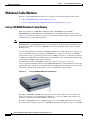
Linksys WCM300 Wideband Cable Modem
When used with the Cisco uBR10012 CMTS, the Linksys WCM300-NA (for DOCSIS),
WCM300-EURO (for EuroDOCSIS), and WCM300-JP (for J-DOCSIS) wideband cable modems
(Figure 2-13) support the acquisition of up to three wideband (bonded) channels: one primary bonded
channel and two secondary bonded channels.
Note
Cisco IOS 12.3(21a)BC3 or a later 12.3BC3 release is required for support of the Linksys WCM300-NA,
WCM300-EURO, and WCM300-JP modems in wideband mode. In wideband mode, the MAC state of
the modem is w-online, and the Cisco uBR10012 uses the Cisco DOCSIS 3.0 Downstream Channel
Bonding feature.
For each wideband channel, the Linksys WCM300 wideband cable modem supports the reception of one
or more bonded RF channels. The Linksys WCM300 software supports the receiving of a 50 MHz
capture window of up to eight downstream channels at 6 MHz per channel or six downstream channels
at 8 MHz per channel. The total of the RF channels in the primary and secondary bonded channels must
comply with the 50 MHz capture-window limitation.
For wideband, the Linksys WCM300 also supports reception of one primary downstream
channel (traditional DOCSIS channel from the uBR10-MC5X20 line card) for MAC management and
signaling messages, and uses the associated traditional DOCSIS upstream channel for return data traffic
and signaling. The upstream channel works as it does in DOCSIS 2.0 cable modems.
Figure 2-13
Linksys WCM300 Wideband Cable Modem
The Linksys WCM300 is DOCSIS 2.0 compatible and can be used in this mode (for example, if the
modem is connected to a non-wideband Cisco CMTS or to a non-Cisco CMTS). The modem is also
backward compatible with existing DOCSIS 1.X networks.
The Linksys WCM300-JP supports J-DOCSIS channel operation: 6 MHz Annex B extension support
with a downstream frequency range of 88 to 860 MHz and an upstream frequency range of 5 to 65 MHz.
Cisco Cable Wideband Solution Design and Implementation Guide, Release 1.0
2-14
OL-10705-02
Chapter 2
Cisco Cable Wideband Components
Wideband Cable Modems
Separate Linksys WCM300 software images are used for DOCSIS and EuroDOCSIS channel widths.
Downstreams in the wideband channel and associated traditional DOCSIS downstreams support
64-QAM and 256-QAM modulation.
Cisco Cable Wideband Solution Design and Implementation Guide, Release 1.0
OL-10705-02
2-15
Chapter 2
Cisco Cable Wideband Components
Wideband Cable Modems
The Linksys WCM300 wideband cable modem has two ports: an F-type 75 ohm connector provides a
cable network attachment, and an RJ-45 port provides a 10/100/1000 Mbps Ethernet connection to the
home or business. More information on the Linksys WCM300 wideband cable modem is available at:
http://www.cisco.com/en/US/products/hw/cable/index.html
Scientific Atlanta DPC2505 and EPC2505 Wideband Cable Modems
When used with the Cisco uBR10012 CMTS, the Scientific Atlanta DPC2505 (for DOCSIS) and
EPC2505 (for EuroDOCSIS) wideband cable modems support the receiving of one wideband channel.
For the Cisco Cable Wideband Solution, Release 1.0, the wideband channel consists of two bonded
downstream RF channels at 6 MHz per channel or at 8 MHz per channel.
In addition to the two bonded downstream RF channels, the Scientific Atlanta DPC2505/EPC2505
modem supports reception of one primary downstream channel (traditional DOCSIS channel from the
uBR10-MC5X20 line card) for MAC management and signaling messages, and uses the associated
traditional DOCSIS upstream channel for return data traffic and signaling. The upstream channel works
as it does in DOCSIS 2.0 cable modems.
•
Unicast data can be received on any downstream channel.
•
DOCSIS 2.0 multicast data can be received only on the primary downstream channel.
The Scientific Atlanta DPC2505 is DOCSIS 2.0 compatible and can be used in this mode (for example,
if the modem is connected to a non-wideband Cisco CMTS or to a non-Cisco CMTS). The modem is
also backward compatible with existing DOCSIS 1.X networks.
Figure 2-14
Scientific Atlanta DPC2505 Cable Modem
The DPC2505/EPC2505 wideband cable modem has an F-type 75 ohm connector for a cable network
attachment and has two data ports: a Gigabit Ethernet port with Auto negotiate and Auto-MDIX, and a
USB 2.0 port.
The DPC2505/EPC2505 also features front-panel LEDs to provide visual feedback of real-time data
transmission and operational status. The DPC2505 features WebWizard, a browser-based user interface.
WebWizard is a powerful tool that facilitates installation and troubleshooting. WebWizard eliminates the
need to load set-up software on the customer premises equipment (CPE).
Cisco Cable Wideband Solution Design and Implementation Guide, Release 1.0
2-16
OL-10705-02
Chapter 2
Cisco Cable Wideband Components
Wideband Cable Modems
The Scientific Atlanta DPC2505 is DOCSIS 2.0 certified, and the EPC2505 is Euro-DOCSIS 2.0
certified. More detailed information and part numbers for the DPC2505 and EPC2505 wideband cable
modems are available at:
http://www.scientificatlanta.com/customers/source/7008362.pdf
Cisco Cable Wideband Solution Design and Implementation Guide, Release 1.0
OL-10705-02
2-17
Chapter 2
Cisco Cable Wideband Components
Wideband CMTS Redundancy and Resiliency
Wideband CMTS Redundancy and Resiliency
The uBR10012 wideband CMTS and related hardware and software provide redundancy and resiliency
to the Cisco Cable Wideband Solution. Reliable, fault-tolerant components and resilient network
technologies automatically identify and overcome failures. The following sections describe the
wideband CMTS redundancy and resiliency features:
•
PRE2 Redundancy and Resiliency, page 2-19
•
uBR10-MC5X20 Line Card Redundancy, page 2-19
•
Wideband SPA Redundancy and Resiliency, page 2-20
•
Edge QAM Redundancy, page 2-21
Table 2-6 summarizes redundancy and resiliency support for the Cisco uBR10012 base system’s
recommended hardware configuration (see Table 2-1). If component failure occurs, the components
listed in Table 2-6 can be replaced without interrupting system operations when redundant components
are correctly installed and configured.
Table 2-6
Cisco uBR 10012 Base System Redundancy and Resiliency
Modular CMTS Component
Redundancy and Resiliency Summary
PRE2 route processors
Two PRE2 modules. The Route Processor
Redundancy Plus feature and DOCSIS Stateful
Switchover provide the PRE2 modules with fast
route processor failover without DOCSIS line
card reboot.
Redundant power supplies
Two DC or AC power entry modules (PEMs). If
one PEM fails, the other PEM immediately begins
providing the required power to the system.
Redundant Timing, Communication, and Control The two TCC+ cards monitor each other's priority
Plus (TCC+) cards
information so that if the active card fails, the
active card role is transferred to the redundant
backup card without loss of data.
Fan assembly module
The fan assembly has four internal fans. If a single
fan fails and the fan assembly is still able to cool
the chassis, the router will continue to function
until the fan assembly module can be replaced.
Redundant Half-Height Gigabit Ethernet (HHGE) Multiple HHGE line cards to support connectivity
line cards
to multiple destinations and to provide network
layer redundancy.
uBR10-MC5X20S/U/H and
uBR10-MC5X20U-D cable interface line cards
N+1 Redundancy provides automatic switchover
and recovery for cable modems connected as
DOCSIS 1.X/2.0 modems in the event that there is
a cable interface line card failure.
Refer to the Cisco uBR10012 Universal Broadband Router Hardware Installation Guide for complete
information on the uBR10012 router’s hardware redundancy.
Cisco Cable Wideband Solution Design and Implementation Guide, Release 1.0
2-18
OL-10705-02
Chapter 2
Cisco Cable Wideband Components
Wideband CMTS Redundancy and Resiliency
PRE2 Redundancy and Resiliency
The Route Processor Redundancy Plus (RPR+) feature and DOCSIS Stateful Switchover (DSSO) in the
Cisco IOS software provide the Cisco uBR10012 router’s PRE2 route processors with fast route
processor failover without DOCSIS line card reboot.
Route Processor Redundancy Plus
The RPR+ feature enables the Cisco uBR10012 router to use two PRE2 route processors in a redundant
configuration: an active and standby PRE2 module. If the active PRE2 module fails, or is removed from
the system, the standby PRE2 detects the failure and initiates a switchover. During a switchover, the
standby PRE2 assumes control of the router, connects with the network interfaces, and activates the local
network management interface and system console.
Using the RPR+ feature, the standby PRE2 module is fully initialized and configured. This allows RPR+
to dramatically shorten the switchover time if the active PRE2 fails, or if a manual switchover is
performed. Because both the startup configuration and running configuration are continually
synchronized from the active to the standby PRE2 route processor, line cards are not reset during a
switchover. The interfaces remain up during this transfer, so neighboring routers do not detect a link flap
(that is, the link does not go down and back up).
The RPR+ feature does not require a full reboot of the system to perform a failover. When the system is
originally initialized, the secondary PRE2 module performs an abbreviated initialization routine—the
module performs all self-checks and loads the Cisco IOS software, but instead of performing normal
systems operations it begins monitoring the primary PRE2 module. If the secondary PRE2 module
detects a failure in the primary module, it can quickly assume the primary responsibility for systems
operations.
During RPR+ switchover, wideband cable modems on the CMTS will stay online. The MAC state for
the wideband cable modem will remain online for a modem registered as a DOCSIS 2.0 modem, or
w-online for a modem registered as a wideband cable modem.
DOCSIS Stateful Switchover
DOCSIS Stateful Switchover increases service uptime by instantaneously switching over between dual
route processors should one processor fail. Switchover takes place without resetting or reloading line
cards or affecting related subsystems or processes. The advantage of DOCSIS Stateful Switchover (with
RPR+) is that a switchover between the primary and standby RP will not require the cable interfaces to
be reset, nor do the modems reregister or go offline. Furthermore, the cable modems retain their
service IDs (SIDs) through the switchover.
For more information on PRE2 and RPR+ and DOCSIS Stateful Switchover, see the document Route
Processor Redundancy Plus on the Cisco uBR10012 Universal Broadband Router.
uBR10-MC5X20 Line Card Redundancy
The Cisco uBR10012 router supports N+1 Redundancy on the cable interface line cards including the
uBR10-MC5X20S/U/H and uBR10-MC5X20U-D line cards, which are used in the Cisco Cable
Wideband Solution.
Cisco Cable Wideband Solution Design and Implementation Guide, Release 1.0
OL-10705-02
2-19
Chapter 2
Cisco Cable Wideband Components
Wideband CMTS Redundancy and Resiliency
N+1 Redundancy can help limit Customer Premises Equipment (CPE) downtime by enabling robust
automatic switchover and recovery in the event that there is a localized system failure. N+1 Redundancy
adds synchronization between Hot Standby Connection-to-Connection Protocol (HCCP) Working
interface configurations and those inherited upon switchover to HCCP Protect interfaces. This makes the
configuration of both easier and switchover times faster.
A single Cisco uBR10012 CMTS can support up to eight uBR10-MC5X20S/U/H and
uBR10-MC5X20U-D cable interface line cards, each featuring five downstream and 20 upstream cable
interfaces for a total of up to 40 downstream and 160 upstream interfaces in the chassis. The eight-card
7+1 Redundancy scheme for the Cisco uBR10012 router supports redundancy for the cable interface line
cards installed in a fully populated Cisco uBR10012 chassis. Other redundancy schemes are designed to
support partial cable interface line card populations in a Cisco uBR10012 chassis.
N+1 Redundancy is made possible with the addition of a Cisco RF Switch to your cable headend
network. A single Cisco RF Switch can be connected to the Cisco uBR10012 CMTS, allowing
deployment of an N+1 Redundancy scheme where one protecting cable interface line card supports from
one to seven Working cable interface line cards in the same chassis.
Note
Both 7+1 and N+1 Redundancy switchover are supported only for cable modems connected as
DOCSIS 1.X/2.0 modems. During 7+1 and N+1 Redundancy switchover, cable modems that are
connected in wideband mode using the failed cable interface line card will lose connectivity. Manual
intervention (for example, use of the clear cable modem wideband reset command) may be required
to bring wideband cable modems w-online again.
For more information on N+1 redundancy for uBR1012 line cards, see the Cisco Cable Modem
Termination System Feature Guide.
Wideband SPA Redundancy and Resiliency
The Wideband SPA provides redundancy and resiliency through a number of mechanisms. The
Wideband SIP and Wideband SPAs support online insertion and removal (OIR) and are hot swappable.
Wideband SPA Redundant Gigabit Ethernet Ports
The Wideband SPA has one active and one redundant Gigabit Ethernet port that is used to send traffic to
the external edge QAM device. If the link state of both Gigabit Ethernet ports (port 0 and 1) is up, the
port that is discovered first as up becomes the active port (forwarding traffic). The other port, when its
link state changes to up, becomes the redundant port. The Port Status LEDs for port 0 and 1 on the
Wideband SPA will be green.
Each Gigabit Ethernet port can discover a link failure between itself and the device to which it is directly
connected. If both Gigabit Ethernet links from the Wideband SPA to the edge QAM device are up,
automatic failover to a redundant link behaves as follows:
•
If both Gigabit Ethernet ports are directly connected to edge QAM device, automatic failover to the
redundant link occurs.
•
If both Gigabit Ethernet ports are connected to, for example, a switch between the Wideband SPA
and the edge QAM device, automatic failover to the redundant link to the switch occurs.
•
In the case where there is a switch between the Wideband SPA and the edge QAM device, the SPA
cannot detect a link failure between the switch and the edge QAM device. No automatic failover to
a redundant Gigabit Ethernet port and link occurs.
Cisco Cable Wideband Solution Design and Implementation Guide, Release 1.0
2-20
OL-10705-02
Chapter 2
Cisco Cable Wideband Components
Where to Find Information on Solution Hardware Components
The show controllers modular-cable command shows the current state of the Wideband SPA’s Gigabit
Ethernet ports. With the Cisco IOS CLI, the Wideband SPA’s Gigabit Ethernet ports are not specified on
the command line as individual Gigabit Ethernet interfaces because the ports work in tandem as a
redundant pair.
Wideband Channel Resiliency
If a wideband channel fails, the wideband cable modem goes offline and re-registers:
•
If another wideband channel is available for the service, the wideband cable modem tries that
channel and comes online.
•
If no other wideband channel is available, the wideband cable modem comes online in
traditional DOCSIS 2.0 mode.
Edge QAM Redundancy
Depending on the edge QAM device that is used, the edge QAM device can have varying degrees of
redundancy. For information on a specific edge QAM device, see the vendor’s documentation for that
device.
Where to Find Information on Solution Hardware Components
Table 2-7 provides a list of the hardware installation documents that are most relevant to the Cisco Cable
Wideband Solution’s components. The complete list of uBR10012 hardware installation and upgrade
guides are available at:
http://www.cisco.com/en/US/products/hw/cable/ps2209/prod_installation_guides_list.html
The Release Notes for Cisco uBR10012 Universal Broadband Router for Cisco IOS Release 12.3(21) BC
are available at:
http://www.cisco.com/univercd/cc/td/doc/product/cable/ubr10k/ub10krns/index.htm
Cisco Cable Wideband Solution Design and Implementation Guide, Release 1.0
OL-10705-02
2-21
Chapter 2
Cisco Cable Wideband Components
Where to Find Information on Solution Hardware Components
Table 2-7
Cisco Hardware Components: Where to Find More Information
Solution Component
Where to Find More Information
uBR10012 chassis
Regulatory Compliance and Safety Information for the Cisco
uBR10012 Universal Broadband Router
Performance Routing Engine 2 (PRE2)
Timing, Communication, and Control Plus card (TCC+)
DC Power Entry Modules (DC PEMs)
AC Power Entry Modules (AC PEMs)
Cisco uBR10012 Universal Broadband Router Hardware
Installation Guide (full installation guide)
Cisco uBR10012 Universal Broadband Router Hardware
Installation Guide (quick start guide)
Fan assembly module
LCD module
uBR10-MC5X20S/U/H and uBR10-MC5X20U-D
cable interface line cards
Cisco uBR10012 Universal Broadband Router Hardware
Installation Guide (full installation guide)
Cisco uBR10-MC5X20S/U/H Cable Interface Line Cards Hardware Installation Guide
Cabling the Cisco uBR10-MC5X20S/U/H Cable Interface Line Card
with Universal Cable Holder—UCH1
Cabling the Cisco uBR10-MC5X20S/U/H Cable Interface Line Card
with Universal Cable Holder—UCH2
Half-Height Gigabit Ethernet (HHGE) network uplink
line card
Cisco uBR10012 Universal Broadband Router Hardware
Installation Guide (full installation guide)
Cisco uBR10012 Universal Broadband Router Gigabit Ethernet
Half-Height Line Card Installation
Wideband SPA Interface Processor (SIP)
Wideband Shared Port Adapter (SPA)
Cisco uBR10012 Universal Broadband Router SIP and SPA
Hardware Installation Guide
Cisco uBR10012 Universal Broadband Router SIP and SPA
Software Configuration Guide
Harmonic NSG 9116 and NSG 9000 edge QAM devices Refer to the vendor documentation.
Scientific Atlanta Continuum DVP XDQA24 edge
QAM device
Refer to the vendor documentation.
Vecima Networks VistaLynx VL1000 edge QAM
device
Refer to the vendor documentation.
Linksys WCM300-NA, WCM300-EURO, and
WCM300-JP wideband cable modems
Release Notes for Linksys WCM300 Cable Modem Software
Cisco Cable Wideband Solution Design and Implementation Guide,
Release 1.0 (this document)
Cisco uBR10012 Universal Broadband Router SIP and SPA
Software Configuration Guide
Scientific Atlanta DPC2505 and EPC2505 wideband
cable modems
Refer to the vendor documentation.
Cisco Cable Wideband Solution Design and Implementation Guide, Release 1.0
2-22
OL-10705-02
C H A P T E R
3
Cisco Cable Wideband Architecture
This chapter explains the architecture used for the Cisco Cable Wideband Solution, Release 1.0. It
explains the following topics:
•
Wideband Channel Bonding, page 3-1
•
Modular CMTS, page 3-4
•
Gigabit Ethernet Switch Functionality, page 3-8
•
Edge QAM Device Functionality, page 3-8
•
Wideband Cable Modem Functionality, page 3-9
The DOCSIS 3.0 Downstream Channel Bonding feature is backward compatible with DOCSIS 1.X/2.0
services and networks.
Wideband Channel Bonding
The DOCSIS 3.0 Downstream Channel Bonding feature uses a selected subset of the DOCSIS 3.0
downstream channel bonding protocol.
With channel bonding, bandwidth is increased by combining or bonding multiple RF channels to create
a wideband channel. The DOCSIS 3.0 Downstream Channel Bonding feature affects the CMTS and the
cable modem as well as the provisioning and network management systems.
The core of the DOCSIS 3.0 Downstream Channel Bonding feature is the sending of DOCSIS packets
for a given service flow across multiple RF channels. The transmit framer in the Cisco Wideband SPA
“stripes” the DOCSIS packets for a given flow and transmits them across the multiple RF channels of
the wideband channel. When the packets are received at the wideband cable modem, the modem’s
receiver framer uses a sequence number embedded in each DOCSIS packet to reassemble the packets
into the original flow.
A wideband channel is a unique combination of downstream RF channels. The wideband CMTS
manages up to 24 wideband channels (12 wideband channels per Wideband SPA). A wideband cable
modem joins a wideband channel. Many wideband cable modems can share the same wideband channel.
In this document, the terms wideband channel, bonded channel, bonding group have the same meaning:
a logical grouping of one or more physical radio frequency (RF) channels over which MPEG-TS packets
are carried.
Cisco Cable Wideband Solution Design and Implementation Guide, Release 1.0
OL-10705-02
3-1
Chapter 3
Cisco Cable Wideband Architecture
Wideband Channel Bonding
The DOCSIS 3.0 Downstream Channel Bonding feature is overlaid on top of and is transparent to a
DOCSIS 2.0 system. In the Cisco Cable Wideband Solution, Release 1.0, these channels are used for
wideband operations:
•
For the wideband downstream channel, the Wideband SPA uses its Gigabit Ethernet port to send data
traffic to the EQAM device. This EQAM device uses one or more QAM output channels, depending
on how the wideband channel is configured, to send striped packets to the wideband cable modem.
In Release 1.0, channel bonding is used for downstream wideband channels only.
– With the Linksys WCM300-NA modem, a downstream wideband channel can combine up to
eight RF channels for a total bandwidth of up to approximately 292 Mbps (at 6 MHz and 256
QAM).
– With the Scientific Atlanta DPC2505 modem, a downstream wideband channel can combine up
to two RF channels for a total bandwidth of up to approximately 74 Mbps (at 6 MHz and 256
QAM).
•
A traditional DOCSIS 2.0 downstream channel is associated with the wideband channel and carries
MAC management and signaling messages. The traditional DOCSIS 2.0 downstream channel does
not carry any bonded traffic. The traditional DOCSIS downstream channel used in this way is called
the primary downstream channel.
•
A traditional DOCSIS 2.0 upstream channel associated with the primary downstream channel
carries return traffic and signaling.
The wideband channel, a primary downstream channel, and an associated upstream channel are
configured for each fiber node that provides the wideband channel.
Figure 3-1 shows a wideband channel consisting of four bonded RF channels on the EQAM device.
These RF channels are asynchronous and carry only bonded traffic. As shown in Figure 3-1, a traditional
DOCSIS 2.0 downstream channel associated with the wideband channel carries MAC layer signaling for
the wideband channel. The upstream channel associated with the wideband channel is a traditional
DOCSIS 2.0 upstream.
Figure 3-1
Channel Bonding to Create a Wideband Channel
Cisco Cable Wideband Solution Design and Implementation Guide, Release 1.0
3-2
OL-10705-02
Chapter 3
Cisco Cable Wideband Architecture
Wideband Channel Bonding
The Cisco Wideband SPA on the uBR10012 router provides the logical RF channels for the DOCSIS 3.0
Downstream Channel Bonding feature. The service provider uses a customized set of Cisco IOS
commands to configure the Wideband SPA for each wideband channel and its associated DOCSIS 2.0
downstream and upstream channels.
Software Configuration for Fiber Nodes
In a cable network, a fiber node is a point of interface between a fiber trunk and the coaxial distribution.
A cable modem is physically connected to only one fiber node. Fiber node software configuration
mirrors the physical topology of the cable network. When configuring fiber nodes with Cisco IOS CLI
commands, a fiber node is a software mechanism to define the following:
•
The set of downstream RF channels that will flow into the fiber node
•
At least one primary downstream channel (traditional DOCSIS downstream channel) for the fiber
node
•
The set of upstream channel ports on the cable interface line card that are connected to the fiber node
and available as upstream channels
The DOCSIS 3.0 Downstream Channel Bonding feature requires that a fiber node be associated with at
least one primary downstream channel (traditional DOCSIS downstream channel). A fiber node can be
associated with more than one primary downstream channel though only one primary downstream
channel is used at any given point in time. On the uBR10-MC5X20 cable interface card, each primary
downstream channel has an upstream port that is statically associated with the downstream port.
For information on configuring fiber nodes, see the Cisco uBR10012 Universal Broadband Router SIP
and SPA Software Configuration Guide.
Virtual Interface Bundling for Primary Downstream Channels and Wideband Channels
The Cisco IOS virtual interface bundling feature is used for the wideband channel and the primary
downstream channels. Both the wideband channel and primary downstream channel must be members
of the same virtual bundle. Virtual interface bundling prevents loss of connectivity on physical interfaces
should there be a failure or problematic insertion and removal (OIR) of one line card in the bundle.
The DOCSIS 3.0 Downstream Channel Bonding feature allows the following scenarios for wideband
channel to primary downstream channel association on a fiber node:
1.
WCMs on one wideband channel use the same primary downstream channel.
2.
WCMs on one wideband channel use different primary downstream channels.
3.
WCMs on different wideband channels use the same primary downstream channel.
4.
Combinations of scenarios 2 and 3.
Figure 3-2 provides an example of wideband channel to primary downstream channel association on a
fiber node.
•
Wideband channel WB1 is associated with primary downstream channels PDC1 and PDC2.
•
Wideband channel WB2 is associated with only primary downstream channel PDC1.
Cisco Cable Wideband Solution Design and Implementation Guide, Release 1.0
OL-10705-02
3-3
Chapter 3
Cisco Cable Wideband Architecture
Modular CMTS
Figure 3-2
Wideband Channels and Primary Downstream Channels on a Fiber Node
WB1
PDC2
NB2
190002
PDC1
NB1
WB2
A WCM on the fiber node can come online on WB1/PDC1, on WB1/PDC2, or on WB2/PDC1. On the
CMTS, WB1, WB2, PDC1, and PDC2 all are members of the same virtual interface bundle.
For information on configuring virtual bundle interfaces, see the Cisco uBR10012 Universal Broadband
Router SIP and SPA Software Configuration Guide.
Modular CMTS
The Cisco Cable Wideband Solution, Release 1.0, uses of a variant of the modular CMTS (M-CMTS)
architecture. With a modular CMTS architecture, the downstream PHY (physical layer) of the CMTS is
located in a separate network element: the edge QAM device. CableLabs defines the M-CMTS
architecture, which is one of the DOCSIS specifications. The M-CMTS architecture and wideband
(DOCSIS 3.0) channel bonding are closely related technology pieces.
The CableLabs specification for the M-CMTS architecture defines changes to the edge QAM device that
require it to be both DOCSIS-aware and synchronized to the DOCSIS subsystem. The Cisco Cable
Wideband Solution, Release 1.0, implementation of the M-CMTS architecture does not place these
requirements on the edge QAM device.
For a single wideband channel, Figure 3-3 shows the M-CMTS architecture as it is used in the Cisco
Cable Wideband Solution, Release 1.0. In this example, two downstream RF channels are bonded
together into one wideband channel. The Gigabit Ethernet (GE) switch is optional.
Figure 3-3
Cisco Cable Wideband M-CMTS Architecture
uBR10012
WCMTS
WAN
WAN
Wideband SIP
Wideband SPA GE
MC5X20
cable interface
line card
Downstream
wideband Optional
channel
GE
switch
Downstream
wideband channel
Edge QAM
device
RF
Wideband
cable modem
Traditional DOCSIS downstream channel
for MAC management and signaling messages
191347
Regional
cable
headend
Traditional DOCSIS upstream channel for
return data traffic and signaling
In the M-CMTS architecture used for the Cisco Cable Wideband Solution, Release 1.0, traditional
CMTS functionality is divided into two network elements as follows:
Cisco Cable Wideband Solution Design and Implementation Guide, Release 1.0
3-4
OL-10705-02
Chapter 3
Cisco Cable Wideband Architecture
Modular CMTS
•
M-CMTS Core—Contains the traditional functionality of a CMTS except for the downstream PHY.
The M-CMTS Core provides CMTS functionality, such as DOCSIS MAC (media access control)
and upstream QPSK and QAM demodulation. DOCSIS MAC includes upstream and downstream
packet transmission services and MAC management message exchanges with cable modems. In the
Cisco Cable Wideband Solution, the Cisco uBR10012 router is the M-CMTS Core device.
•
Edge QAM (EQAM) Device—Connects to the M-CMTS Core and contains PHY-related hardware,
such as QAM modulators. For input, the EQAM device communicates with the M-CMTS through
redundant Gigabit Ethernet interfaces. For output, the EQAM device has multiple QAM modulators
and RF upconverters that connect to a hybrid fiber coaxial (HFC) network. In the Cisco Cable
Wideband Solution, four EQAM devices are tested for interoperability with solution components:
– Scientific Atlanta Continuum DVP eXtra Dense QAM Array 24 (XDQA24)
– Harmonic Narrowcast Services Gateway (NSG) 9116
– Harmonic Narrowcast Services Gateway (NSG) 9000
– Vecima Networks VistaLynx VL1000
Benefits of M-CMTS Architecture
Some of the benefits of a modular CMTS architecture are described in these sections:
•
Cost Effective Architecture, page 3-5
•
Multiservice Architecture, page 3-6
Cost Effective Architecture
The Cisco Cable Wideband Solution, Release 1.0, can use the MSO’s existing network. Deployed
uBR10012 routers that are used as a DOCSIS 1.x/2.0 CMTS’s can be upgraded to a modular CMTS’s
that support wideband cable by adding on hardware (the Cisco Wideband SIP and SPA) and upgrading
software. Some existing external QAM array devices used for video on demand (VOD), with a software
upgrade, may be able to be employed as the edge QAM device. For edge QAM devices that have been
tested for interoperability, see the “External Edge QAM Device” section on page 2-11.
MSOs can repurpose their existing network infrastructure, including existing fiber nodes, for wideband
cable. The benefits of the M-CMTS architecture include:
•
Takes advantage of the lower cost, lower power requirements, and higher density of edge QAM
devices.
•
Uses less-expensive external QAM arrays for downstream wideband channels. This is more cost
effective than locating the downstream QAMs in the CMTS chassis.
•
Saves operating costs by avoiding rewiring and moving customers to new systems.
With traditional CMTS architecture, adding downstream RF channels for a wideband channel would
mean also adding multiple upstreams. With the M-CMTS architecture, multiple downstream
RF channels can be aggregated into a wideband channel without adding any additional upstreams. This
independent scaling of downstream channels makes wideband channels economically feasible.
Cisco Cable Wideband Solution Design and Implementation Guide, Release 1.0
OL-10705-02
3-5
Chapter 3
Cisco Cable Wideband Architecture
Modular CMTS
Multiservice Architecture
With M-CMTS architecture, the use of external edge QAM devices allows MSOs to use the same
network resources for a video on demand (VOD) network and a Cisco wideband cable network. With
updated firmware, some edge QAM devices can be used for VOD and for wideband channels though
individual output QAM channels in the device cannot be shared.
The wideband channel uses the edge QAM device for downstream data traffic, and uses the M-CMTS’s
uBR10-MC5X20 cable interface line card for upstream traffic and for downstream MAC management
and signaling messages.
In the Cisco Cable Wideband Solution, Release 1.0, traditional DOCSIS 1.X/2.0 services are supported
by the CMTS; uBR10-MC5X20 cable interface line cards (not edge QAM devices) are used for these
services.
A multiservice architecture (see Figure 3-4) with converged IP triple play (voice, data, and video
services) on wideband channels is the ultimate goal for DOCSIS 3.0 services.
Figure 3-4
M-CMTS Multiservice Architecture
Video over MPEG-TS
Data over IP
Voice over IP
uBR10012
M-CMTS
Core
DOCSIS 3.0 Downstream
Channel Bonding
Edge QAM
device
Traditional DOCSIS 1.X/2.0 channels
Note
190005
Video over IP
In the Cisco Cable Wideband Solution, Release 1.0, the uBR1012 router currently supports a data-only
service on wideband channels. A Cisco Cable Wideband Solution, Release 1.0, system does not
currently support video or voice on wideband channels.
M-CMTS Interactions with Wideband Cable Modems
The following sections provide information on interactions between the M-CMTS and wideband cable
modems:
•
MAC Domains, page 3-6
•
Addressing, page 3-7
•
Security, page 3-7
•
Quality of Service, page 3-8
MAC Domains
A DOCSIS MAC Domain is a logical subcomponent of a CMTS and is responsible for implementing all
DOCSIS functions on a set of downstream channels and upstream channels. All MAC Domain
operations are performed by the Core CMTS’s uBR10-MC5X20 cable interface line cards. A CMTS
MAC Domain contains at least one downstream channel and at least one upstream channel. Each
downstream channel or upstream channel is contained by a single MAC Domain.
Cisco Cable Wideband Solution Design and Implementation Guide, Release 1.0
3-6
OL-10705-02
Chapter 3
Cisco Cable Wideband Architecture
Modular CMTS
A MAC domain is responsible for all MAC Management Messages to the set of cable modems that are
registered on that MAC Domain. A cable modem is registered to only a single MAC Domain.
A MAC Domain provides Layer 2 data forwarding services between the CMTS and the set of cable
modems registered to that MAC Domain.
In the downstream direction, the MAC Domain classifies downstream packets into downstream service
flows based on Layer 2, 3, and 4 information in the packets. The MAC Domain then schedules the
packets from each downstream service flow onto the set of downstream channels of the MAC domain.
The CMTS assigns a downstream service flow to either a single downstream RF channel or to a
Downstream Bonding Group for a wideband channel. A downstream sequence of bonded packets is
identified at the CMTS and wideband cable modem by a Bonding Group ID (BG ID). Packets destined
to different wideband cable modems can share the same Bonding Group ID. The CMTS assigns a
downstream service flow to either a single downstream RF channel or to a downstream Bonding Group
for a wideband channel.
For the Scientific Atlanta DPC2505 or EPC2505 wideband cable modem, each of the modem's unicast
service flows is sent as a bonded group and is tied to the modem's bonded downstream channel. A
downstream sequence of unicast bonded packets is identified at the CMTS and the cable modem by a
unique Downstream Service Identifier (DSID). Multicast traffic on bonded downstream channels is not
supported. Multicast service flows that the modem sees on the bonded downstream channel are
discarded.
In the upstream direction, the behavior and handling of traffic by the CMTS is identical to the
DOCSIS 2.0 behavior and handling.
Addressing
All addressing is done with Ethernet and IP addresses. The wideband cable modem uses the same IP
address space as a standard cable modem so it is able to use the same DHCP procedure to procure an IP
address.
The DOCSIS 3.0 Downstream Channel Bonding feature does not limit the number of wideband cable
modems that can exist on a downstream channel. The limit is set either by the availability of bandwidth,
or by the 8175 service identifiers (SIDs) limit in DOCSIS 2.0.
Because wideband channels and a traditional DOCSIS channel can be within the same subnet, a
wideband cable modem can be moved between services without the need to change the IP address space
of the home network.
Since the IP address space is homogeneous, it is not necessary to have a NAT function in the wideband
cable modem. The rules for distribution of IP address for a home network with a wideband cable modem
are the same as for a DOCSIS 2.0 cable modem.
Security
A wideband channel uses Baseline Privacy Plus (BPI+) for its link level encryption. As with
DOCSIS 2.0, BPI+ provides cable modem users with data privacy across the cable network by
encrypting traffic flows between the wideband cable modem and the wideband CMTS. BPI+ also
provides MSOs with protection against theft of service.
The wideband cable modem uses the same BPI+ keys on its wideband channels as it does on its
traditional DOCSIS channel. The wideband cable modem uses the BPI+ keys negotiated on the primary
service flow of the traditional DOCSIS downstream channel for the service flows on the wideband
channel.
Cisco Cable Wideband Solution Design and Implementation Guide, Release 1.0
OL-10705-02
3-7
Chapter 3
Cisco Cable Wideband Architecture
Gigabit Ethernet Switch Functionality
Quality of Service
For quality of service (QoS) on a wideband downstream channel, a wideband cable modem can be
assigned multiple service flows. Only Best Effort (BE) service flows are currently supported. The CMTS
sends data traffic on a non-guaranteed best-effort basis.
For the traditional DOCSIS upstream channel associated with a wideband channel, QoS capabilities
supported are identical to those in DOCSIS 2.0.
Gigabit Ethernet Switch Functionality
The Gigabit Ethernet (GE) switch is an optional device that receives downstream packets from the Cisco
Wideband SPA and passes the packets to the edge QAM device. The Gigabit Ethernet switch is used for
these purposes:
•
To concentrate traffic from multiple Gigabit Ethernet links to a smaller number of Gigabit Ethernet
links prior to fiber transport to the edge QAM devices
•
To provide 1+1 or N+1 redundancy for downstream Gigabit Ethernet links
•
To multiplex wideband DOCSIS traffic and video traffic onto the same edge QAM devices
If more than two EQAM devices are required for two Wideband SPAs, a Gigabit Ethernet switch is
needed to connect the SPAs to the EQAM devices.
If video-on-demand (VOD) traffic and the RF channels for wideband channels are mixed on the same
EQAM device, a Gigabit Ethernet switch is required.
When an RF channel for a wideband channel is configured using Cisco IOS commands on the uBR10012
router, the rf-channel command’s mac-address argument specifies the MAC address for the next-hop
interface on the switch if it is a Layer-2 GE switch. The rf-channel command’s ip-address argument
specifies the IP address of the Gigabit Ethernet interface on the edge QAM device. The MAC address on
the switch and the IP address on the EQAM device are used to route downstream traffic for the RF
channel to the correct destinations.
Edge QAM Device Functionality
The edge QAM (EQAM) device receives wideband as MPEG-TS over IP on its Gigabit Ethernet
interfaces. The edge QAM device extracts the MPEG-TS packets from the MPEG-TS over IP stream and
routes them to the proper QAM RF outputs to the HFC plant for transmission to the wideband cable
modem.
The edge QAM devices are not involved in the active management of bandwidth or QOS for wideband
channels. The edge QAM devices are not aware of the IP addressing used by the wideband cable
modems.
A single QAM’s total bandwidth can be divided up and statically allocated to more than one wideband
channel. When a wideband channel is configured on the CMTS, the wideband channel uses multiple
specified logical RF channels on the Wideband SPA. Each RF channel is associated with a QAM output
on the edge QAM device.The bandwidth of an RF channel can be divided between one or more wideband
channels as long as the total allocated bandwidth for an RF channel (and QAM) does not exceed 100
percent. For more information on configuring RF channels, see the Cisco uBR10012 Universal
Broadband Router SIP and SPA Software Configuration Guide.
Cisco Cable Wideband Solution Design and Implementation Guide, Release 1.0
3-8
OL-10705-02
Chapter 3
Cisco Cable Wideband Architecture
Wideband Cable Modem Functionality
The QAM channels on the edge QAM device do not need to be adjacent. If certain QAM channels have
already been assigned to non-DOCSIS uses, the DOCSIS 3.0 Downstream Channel Bonding feature uses
the channels that are available. The system does impose certain constraints. For example, if the QAMs
are frequency stacked, certain QAMs will have to be adjacent.
Wideband Cable Modem Functionality
The wideband cable modem is a standalone device capable of interoperation with an industry standard
DOCSIS 2.0 compatible CMTS, but it supports wideband operation when used with a wideband CMTS.
At any one time, the wideband cable modem operates in one of two ways:
•
As a traditional DOCSIS 2.0 cable modem, it receives all downstream traffic as non-bonded traffic
on its traditional downstream.
•
As a wideband cable modem, it receives all downstream traffic as bonded traffic—a wideband
channel consisting of one or more RF downstreams.
This discussion focuses on the modem’s role as a wideband cable modem. The explanations in this
section are generic and apply to all wideband cable modems supported by the Cisco Cable Wideband
Solution, Release 1.0.
Wideband cable modem functionality may vary depending on the wideband cable modem. For
implementation information on specific wideband cable modems, see the “Wideband Cable Modem
Behavior” section on page 4-6.
Wideband Cable Modem Design and Operation
The wideband cable modem is backward compatible with DOCSIS 2.0 and contains a complete
DOCSIS 2.0 core. If a wideband channel is not available, the wideband cable modem can operate strictly
as a DOCSIS 2.0 cable modem. Figure 3-5 shows a simplified block view of the wideband cable modem.
Figure 3-5
Wideband Cable Modem Block View
Wideband cable modem
Wideband
Receiver
Wideband
Framer
10/100/1000
Ethernet
HFC
CPU
190006
DOCSIS
2.0
The wideband cable modem has a wideband receiver that receives the multiple RF channels of a bonded
channel. It also has a wideband framer that decodes the signal from the wideband receiver and extracts
the packets for the 10/100/1000 Mbps Ethernet home network.
The wideband cable modem identifies itself as being wideband-capable during the configuration
process. This allows the DOCSIS TFTP provisioning server to enable or disable wideband mode, and to
choose the appropriate configuration parameters.
Cisco Cable Wideband Solution Design and Implementation Guide, Release 1.0
OL-10705-02
3-9
Chapter 3
Cisco Cable Wideband Architecture
Wideband Cable Modem Functionality
A wideband channel uses the same DOCSIS frame format as a traditional DOCSIS channel uses. The
channel just has more bandwidth. A new extended header for wideband has been added to the DOCSIS
protocol. The extended header defines the logical wideband channel and a sequence number that the
wideband cable modem uses for re-sequencing the wideband packets.
The CISCO-CABLE-WIDEBAND-MODEM-MIB for the wideband cable modem is supported and is an
extension to the existing cable modem MIB.
Cisco Cable Wideband Solution Design and Implementation Guide, Release 1.0
3-10
OL-10705-02
C H A P T E R
4
Implementing and Configuring the Solution
This chapter provides implementation and configuration information for the Cisco Cable Wideband
Solution, Release 1.0, and contains the following topics:
•
Wideband CMTS Configuration, page 4-1
•
Wideband Cable Modem Behavior, page 4-6
•
Supported MIBs, page 4-10
•
Known Restrictions, page 4-10
Wideband CMTS Configuration
This section provides overview information on the wideband CMTS configuration tasks:
•
Configuring Base CMTS Components, page 4-1
•
Configuring Wideband CMTS Components, page 4-2
This section also lists documents where you can find the detailed information needed to configure the
Cisco IOS software for the uBR10012 router components, including the components needed for the
Cisco Cable Wideband Solution, Release 1.0.
Configuring Base CMTS Components
The base CMTS is the Cisco uBR10012 router with the components needed for DOCSIS 1.x/2.0
operation. Wideband cable components can be added to the Cisco uBR10012 base system so that it can
be used as a wideband CMTS. For wideband cable operation, the configuration tasks for the base CMTS
components are similar to the configuration tasks used for DOCSIS 1.x/2.0 operation. The base CMTS
can be used as a DOCSIS 1.x/2.0 CMTS.
For wideband cable operation, one additional configuration task is required on the uBR10-MC5X20
cable interface line cards that will be used for primary downstream channels on fiber nodes. For each
fiber node, a traditional DOCSIS downstream channel is used to carry MAC management and signaling
messages, and the associated traditional DOCSIS upstream channel is used for return data traffic and
signaling. The traditional DOCSIS downstream channel used in this way is referred to as the primary
downstream channel.
Cisco Cable Wideband Solution Design and Implementation Guide, Release 1.0
OL-10705-02
4-1
Chapter 4
Implementing and Configuring the Solution
Wideband CMTS Configuration
All wideband channels used on a fiber node and all associated primary downstream channels on Cisco
uBR10-MC5X20 cable interface line cards must be configured to belong to the same virtual bundle
interface. For detailed information on this configuration task, see the “Configuring Wideband Channels
and Primary Downstream Channels as Virtual Bundle Members” section in the Cisco uBR10012
Universal Broadband Router SIP and SPA Software Configuration Guide.
Table 4-1 provides a list of the software configuration documents that are likely to be useful for
configuring the Cisco Cable Wideband Solution, Release 1.0, base CMTS components.
Table 4-1
Base CMTS Components Configuration: Where to Find Information
Solution Component
Where to Find Information
Cisco uBR10012 router
(general and feature-specific
configuration)
Release Notes for Cisco uBR10012 Universal Broadband Router for Cisco IOS
Release 12.3 BC (which includes information on Cisco IOS Release 12.3(21)BC)
Cisco uBR10012 Universal Broadband Router Software Configuration Guide
Cisco Cable Modem Termination System Feature Guide
Performance Routing Engine 2 (PRE2)
Route Processor Redundancy Plus for the Cisco uBR10012 Universal
Broadband Router
Cisco uBR-MC5X20 line cards
Chapter 3, “Configuring Cable Interface Features for the Cisco uBR10012
Router,” in the Cisco uBR10012 Universal Broadband Router Software
Configuration Guide
“Cable Interface Bundling and Virtual Interface Bundling for the Cisco CMTS”
in the Cisco Cable Modem Termination System Feature Guide
“N+1 Redundancy for the Cisco Cable Modem Termination System” in the
Cisco Cable Modem Termination System Feature Guide
Half-Height Gigabit Ethernet (HHGE)
network uplink line cards
Configuring the Half-Height Gigabit Ethernet Line Card for the Cisco
uBR10012 Universal Broadband Router
The technical documentation set for the Cisco uBR10012 router includes many documents not shown in
Table 4-1 that are useful for configuring this CMTS. The Cisco uBR10012 documentation set can be
accessed from this web site area:
http://www.cisco.com/en/US/products/hw/cable/ps2209/tsd_products_support_series_home.html
Configuring Wideband CMTS Components
The wideband CMTS components are added to the base CMTS components to make the CMTS
wideband capable. This section provides overview information on configuring the wideband CMTS
components:
•
Configuring the Wideband SIP and Wideband SPA, page 4-3
•
Configuring the Edge QAM Device Configuration, page 4-3
•
Configuring the Gigabit Ethernet Switch, page 4-5
Cisco Cable Wideband Solution Design and Implementation Guide, Release 1.0
4-2
OL-10705-02
Chapter 4
Implementing and Configuring the Solution
Wideband CMTS Configuration
Configuring the Wideband SIP and Wideband SPA
The wideband CMTS components that require configuration include the Cisco Wideband SIP and Cisco
Wideband SPA. Cisco IOS commands are issued on the uBR10012 router to configure the Wideband SIP
and SPA. An outline of the configuration tasks needed for the Wideband SIP and SPA is as follows:
•
Preprovisioning of the Wideband SIP and Wideband SPA
•
Setting General Configuration Values for the Wideband SPA
•
Configuring RF Channels
•
Configuring Fiber Nodes
•
Configuring Wideband Channels and Primary Downstream Channels as Virtual Bundle Members
•
Setting Optional Configuration Values
For information on the preceding tasks and for reference information on the Cisco IOS commands used
for Wideband SIP and SPA configuration, see the Cisco uBR10012 Universal Broadband Router SIP and
SPA Software Configuration Guide.
Configuring the Edge QAM Device Configuration
Edge QAM (EQAM) device configuration is device-specific and implementation-specific.
•
For the Scientific Atlanta Continuum DVP XDQA24 device, the Continuum DVP eXtra Dense QAM
Array 24 Configuration Guide contains configuration information. See the appendix “Cisco
Wideband Applications” in that document for information on configuring this EQAM device for
wideband.
•
For information on configuring other EQAM devices, refer to the device’s documentation.
Regardless of the edge QAM device or implementation, these items are used for Wideband SPA
configuration and must be configured on each EQAM device:
•
For the edge QAM device:
– IP address of the EQAM device’s Gigabit Ethernet interface (input port)
– MAC address of the EQAM device’s Gigabit Ethernet interface (input port)
•
For each of the EQAM device’s QAM outputs that will be used for a Wideband SPA RF channel:
– Center frequency of the QAM output
– UDP number of the QAM output
The IP address, MAC address, frequency, and UDP port configured on the edge QAM device are
specified when configuring RF channels on the CMTS. Be certain to verify that the RF-channel values
set with rf-channel (issued on the CMTS) match the values configured on the edge QAM device.
Note
If a Layer-2 Gigabit Ethernet switch is used to connect the Wideband SPA to the EQAM device, the MAC
address specified in the rf-channel command is the MAC address of the switch’s Gigabit Ethernet
interface.
An RF channel and EQAM configuration worksheet such as the one shown in Table 4-2 may be useful
for coordinating Wideband SPA RF channel and EQAM device configuration. A Wideband SPA supports
either 18 or 24 RF channels depending on how the SPA is configured. For more information, see the
description of the rf-channel command in the Cisco uBR10012 Universal Broadband Router SIP and
SPA Software Configuration Guide.
Cisco Cable Wideband Solution Design and Implementation Guide, Release 1.0
OL-10705-02
4-3
Chapter 4
Implementing and Configuring the Solution
Wideband CMTS Configuration
Table 4-2
RF Channel and EQAM Configuration Worksheet
EQAM Device
Wideband SPA
RF Channel
GE Input
IP Address
GE Input
MAC Address
QAM Output
QAM Output
Frequency
UDP
Port Number
0
1
2
3
4
5
6
7
8
9
10
11
12
13
14
15
16
17
18
19
20
21
22
23
Cisco Cable Wideband Solution Design and Implementation Guide, Release 1.0
4-4
OL-10705-02
Chapter 4
Implementing and Configuring the Solution
Wideband CMTS Configuration
Configuring the Gigabit Ethernet Switch
A Gigabit Ethernet (GE) switch linking the Cisco Wideband SPAs and the edge QAM (EQAM) devices
is optional except when more than two EQAM devices are required for two Wideband SPAs, or when
video-on-demand (VOD) traffic and the RF channels for wideband channels are mixed on the same
EQAM device. The configuration of the Gigabit Ethernet switch is device-specific and
implementation-specific, but it is recommended that virtual LANs (VLANs) be used to create separate
broadcast domains for the traffic of each Wideband SPA.
Figure 4-1 shows an example of VLAN usage. Wideband SPA 1 uses the QAM outputs on EQAM A and
EQAM B. Wideband SPA 2 uses the QAM outputs on EQAM C and EQAM D.
•
VLAN 1 carries traffic for Wideband SPA 1.
•
VLAN 2 carries traffic for Wideband SPA 2.
Both the Wideband SPAs and EQAM devices have redundant Gigabit Ethernet links that are members
of the appropriate VLANs.
Figure 4-1
VLANs for Wideband Traffic
uBR10012
CMTS
VLAN 1
VLAN 1
Wideband SPA 2 GE
GE
EQAM A
GE
EQAM B
GE
EQAM C
VLAN 2
VLAN 2
191359
Wideband SPA 1 GE
VLAN 1
Cisco Cable Wideband Solution Design and Implementation Guide, Release 1.0
OL-10705-02
4-5
Chapter 4
Implementing and Configuring the Solution
Wideband Cable Modem Behavior
Wideband Cable Modem Behavior
This section provides information on the wideband cable modems and their interactions with the CMTS.
The following topics are discussed:
•
Linksys WCM300-NA, WCM300-EURO, and WCM300-JP Modems, page 4-6
•
Scientific Atlanta DPC2505 and EPC2505 Modems, page 4-8
•
CMTS Interactions with Wideband Cable Modems, page 4-9
Linksys WCM300-NA, WCM300-EURO, and WCM300-JP Modems
With the Linksys WCM300-NA, WCM300-EURO, and WCM300-JP wideband cable modems, Cisco’s
DOCSIS 3.0 Downstream Channel Bonding feature supports downstream data service to the cable
modem on multiple bonded downstream channels. The Linksys WCM300 wideband cable modem
supports the receiving of up to three wideband downstream channels:
•
One primary bonded channel
•
Up to two secondary bonded channels
The primary bonded channel is the wideband channel on which the wideband cable modem receives all
of its unicast traffic and some multicast traffic. The cable modem may identify the primary bonded
channel and any secondary bonded channels to the CMTS at cable modem registration time. The
DOCSIS configuration file may define the primary bonded channel for the CMTS to assign to the cable
modem.
Secondary bonded channels are the wideband channels on which the wideband cable modem receives
additional multicast data streams. The DOCSIS configuration file defines the secondary bonded
channels for the modem to pass to the CMTS. Secondary bonded channels are intended to receive
multicast traffic such as broadcast video that is not available on the primary bonded channel.
When the wideband cable modem registers with one primary and one or more secondary wideband
channels, it accepts multicast packets from all associated wideband channels. The CMTS ensures that a
multicast packet is not forwarded on the primary and secondary wideband channels simultaneously.
A primary bonded channel cannot also be configured as a secondary bonded channel, and vice-versa.
Primary and secondary bonded channels can be configured on the CMTS with the cable
bonding-group-id command and with the DOCSIS configuration file using TLVs (primary bonding
group ID and secondary bonding group ID).
The Linksys WCM300 wideband cable modem implements a subset of the DOCSIS 3.0 protocol for
channel bonding. Channel bonding is accomplished by the use of a per-packet sequence number to
enable the wideband cable modem to deliver, in order, the packets from multiple RF channels that are
destined to the CPE device. The WCM300 modem supports up to 16 independent resequencing engines
for the receiving of bonded unicast traffic and bonded multicast traffic over its three bonded channels.
Cisco Cable Wideband Solution Design and Implementation Guide, Release 1.0
4-6
OL-10705-02
Chapter 4
Implementing and Configuring the Solution
Wideband Cable Modem Behavior
DOCSIS Configuration File for Wideband on Linksys WCM300 Modems
The Linksys WCM300 wideband cable modem obtains a DOCSIS configuration file as it does in
DOCSIS 2.0. For wideband operation, the file may contain three wideband-related
Type/Length/Value (TLV) encodings.
Note
•
Primary bonding group ID
•
Bonded channel enable
•
Secondary bonding group ID
The preceding TLVs can optionally be specified in the DOCSIS configuration file. These TLVs are not
required for the Linksys WCM300 modem to operate in wideband mode (w-online).
All three TLVs are encoded as vendor-specific options (type 43) to facilitate interoperability and reduce
future compatibility issues.
Primary Bonding Group ID
The primary bonding group ID option is encoded as subtype 14:
•
Type.Subtype: 43.14
•
Length: 2
•
Value: primary bonding group ID
The primary bonding group ID option allows the provisioning system to force the wideband cable
modem to use a particular primary bonded downstream channel. The modem can use a single primary
bonded channel for unicast and multicast traffic. When the primary bonding group ID value is present,
the CMTS assigns the wideband cable modem to the wideband-channel interface identified by the
configured bonding group ID. If the CMTS is unable to assign the wideband cable modem to the
wideband-channel interface specified by the configured bonding group ID, the CMTS causes the
wideband cable modem to fail registration.
Only a single occurrence of the primary bonding channel ID option may be specified in the DOCSIS
configuration file. The total of the RF channels in the primary and secondary bonded channels must
comply with the 50 MHz capture-window limitation of the Linksys WCM300 modem.
Note
If a wideband channel is specified as a primary bonded channel in the DOCSIS configuration file, the
channel must be identically specified as a primary bonded channel in the CMTS active, running
configuration file. The cable bonding-group-id command specifies whether a bonding group is a
primary or secondary bonding group. For information on this command, see the Cisco uBR10012
Universal Broadband Router SIP and SPA Software Configuration Guide.
Bonded Channel Enable
The bonded channel enable option is encoded as subtype 15:
•
Type.Subtype: 43.15
•
Length: 1
•
Value: 0 equals Disable, and 1 equals Enable
Cisco Cable Wideband Solution Design and Implementation Guide, Release 1.0
OL-10705-02
4-7
Chapter 4
Implementing and Configuring the Solution
Wideband Cable Modem Behavior
The bonded channel enable option allows the provisioning system to require that a wideband cable
modem operate in traditional DOCSIS 2.0 mode. When the bonded channel enable option has a value of
0 (disable), the CMTS ensures that a wideband-channel interface is not assigned to the wideband cable
modem at registration time.
Only a single occurrence of the bonded channel enable option may be specified in the DOCSIS
configuration file.
Secondary Bonding Group ID
The secondary bonding group ID option is encoded as sub-type 16.
•
Type.Subtype: 43.16
•
Length: 2
•
Value: secondary bonding group ID
The secondary bonding group ID option allows the provisioning system to specify secondary bonded
downstream channels for the wideband cable modem to use. The modem can use one or two secondary
bonded channels for multicast traffic. If the configured secondary bonding group ID is not valid, the
CMTS causes the wideband cable modem to fail registration
Up to two secondary bonding group IDs can be specified in the DOCSIS configuration file. The total of
the RF channels in the primary and secondary bonded channels must comply with the 50 MHz
capture-window limitation of the Linksys WCM300 modem.
Note
If a wideband channel is specified as a secondary bonded channel in the DOCSIS configuration file, the
channel must be identically specified as a secondary bonded channel in the CMTS active, running
configuration file. The cable bonding-group-id command specifies whether a bonding group is a
primary or secondary bonding group. For information on this command, see the Cisco uBR10012
Universal Broadband Router SIP and SPA Software Configuration Guide.
Scientific Atlanta DPC2505 and EPC2505 Modems
The Scientific Atlanta DPC2505 and EPC2505 wideband cable modem makes use of Broadcom
Corporation’s BCM93381 cable modem chip. The BCM93381 chip provides three tuners, allowing the
three downstream receivers to be independently tuned to any frequency. The M-CMTS and the DPC2505
wideband cable modem use these three channels as follows:
•
It uses one of these downstream RF channels as its primary downstream channel for MAC
management and signalling messages.
•
It uses the other two downstream RF channels as non-primary downstream channels. These two RF
channels can be bonded together to form one wideband channel.
The DPC2505/EPC2505 wideband cable modem uses a selected subset of the DOCSIS 3.0 protocol for
channel bonding. Channel bonding is the transmission of a stream of packets across multiple RF
channels with the use of sequence numbers to ensure the modem receiver delivers packets in the proper
order to the CPE. The DPC2505/EPC2505 wideband cable modem filters packets on a Destination
Address and Security Association Identifier (SAID). The DPC2505/EPC2505 modem supports up to 16
independent re-sequencing contexts.
The DPC2505/EPC2505 wideband cable modem does not support multicast traffic on the wideband
channel. Multicast service flows that the modem sees on the bonded downstream channel are discarded.
Cisco Cable Wideband Solution Design and Implementation Guide, Release 1.0
4-8
OL-10705-02
Chapter 4
Implementing and Configuring the Solution
Wideband Cable Modem Behavior
The configuration file used for the Scientific Atlanta DPC2505/EPC2505 wideband cable modem is
identical to a DOCSIS 2.0 configuration file. DOCSIS 2.0 configuration file tools like the Cisco
Broadband Configurator can be used to create configuration files for this modem.
Automatic Adjustments During Scientific Atlanta DPC2505 and EPC 2505 Registration
During modem registration, upon reception of the REG-RSP from the CMTS, the Scientific Atlanta
DPC2505/EPC2505 modem first checks for presence and correctness of the various encodings.
•
If any encodings are incorrectly formatted or exceed the modem's capabilities, the wideband cable
modem may detect this and immediately send a REG-ACK message with a confirmation code
indicating failure. The confirmation code will be reject-bad-rcc(208) if the RCC encoding is bad, or
reject-other(1) if some other problem is found.
•
If encodings appear to be valid, the wideband cable modem attempts to tune its non-primary
receivers to the non-primary downstream channels specified in the RCC. The RCC may specify zero,
one, or two non-primary downstream channels. If the cable modem fails to tune to the designated
non-primary downstream channels, it will send a REG-ACK with confirmation code
reject-bad-rcc(208).
In the case of wideband channels overlapping on some sets of QAMs, if the DPC2505 modem rejects the
registration with confirmation code of reject-bad-rcc(208), something is wrong— either an incorrect
plant topology configuration or a bad tuner in the cable modem. The CMTS records this occurrence.
When the same cable modem tries to register again, the CMTS chooses different wideband channels
preferably residing on a different sets of QAMs.
The process continues until the wideband cable modem successfully registers on a wideband channel or
all choices of wideband channels are exhausted. If all choices are exhausted, the CMTS put the Scientific
Atlanta DPC2505 modem in DOCSIS 2.0 mode on its next attempt to register.
A timeout value of 24 hours is defined for the CMTS to clear the bad QAM status recorded for each CM.
Therefore, the wideband cable modem is allowed to retry the bad set of QAMs in the future.
CMTS Interactions with Wideband Cable Modems
This section provides information CMTS interactions with wideband cable modems:
•
Registration for Wideband Cable Modems, page 4-9
•
Load Balancing for Wideband Cable Modems, page 4-10
In these sections, all statements are generic and apply to the following modems:
•
Linksys WCM300-NA
•
Linksys WCM300-EURO
•
Linksys WCM300-JP
•
Scientific Atlanta DPC2505
•
Scientific Atlanta EPC2505
Registration for Wideband Cable Modems
After the wideband cable modem completes the initialization process on the primary downstream
channel, the CMTS uses the REG-RSP message to enable multiple downstream RF channel operation
(wideband channel operation) and to assign channels to the cable modem.
Cisco Cable Wideband Solution Design and Implementation Guide, Release 1.0
OL-10705-02
4-9
Chapter 4
Implementing and Configuring the Solution
Supported MIBs
Consistent with DOCSIS 3.0, the assignment of multiple channels takes place at two layers. The lower
layer is that of physical receiver configuration, or the Receive Channel Set, of the cable modem. The
CMTS uses a specific subset of DOCSIS 3.0 Receive Channel Configuration (RCC) encodings to tell the
wideband cable modem what center frequencies to use for its primary downstream channel receiver and
its non-primary downstream channel receivers.
With the wideband cable modem as per DOCSIS 3.0, bonding and sequencing of traffic can take place
across all channels of a cable modem's Receive Channel Set, or across any subset of these channels. A
second, higher layer of channel assignment deals with bonding and resequencing. This higher layer is
handled by assignment of a Downstream Service Identifier (DSID) for each independent sequence
number space. In the REG-RSP message, the CMTS uses a subset of DOCSIS 3.0 DSID encodings to
tell the cable modem the DSID values to recognize and the channels and resequencing timeouts that are
associated with each DSID.
Load Balancing for Wideband Cable Modems
If multiple wideband channels are available on the same fiber node, and the wideband cable modem
comes online with one of the wideband channels, the CMTS has the choice of assigning it to a different
wideband channel. In this case, a simple random load balancing algorithm distributes the cable modems
on the fiber node across the multiple wideband channels.
If the CMTS has a choice between a wideband channel consisting of one RF channel and another channel
consisting of two RF channels, the CMTS uses a weighted random load-balancing algorithm to
determine the wideband channel that the wideband cable modem will use. The wideband channel with
two RF channels is weighted so that it has two-thirds of a chance of being chosen while the wideband
channel with one RF channel has one-third of a chance.
Supported MIBs
The following MIBs are supported in Cisco IOS Release 12.3(21)BC and later for the Cisco uBR10012
router and the Cisco Wideband SIP and Wideband SPA:
•
ENTITY-MIB
•
CISCO-CABLE-WIDEBAND-MIB
•
IF-MIB
•
CISCO-VENDORTYPE-OID-MIB
For more information about MIB support on a Cisco uBR10012 router, refer to the Cisco CMTS
Universal Broadband Router MIB Specifications Guide.
For information about MIBs associated with edge QAM devices or wideband cable modems, refer to the
vendor documentation.
Known Restrictions
The following restrictions apply to the Cisco Wideband SPA for Cisco IOS Release 12.3(21)BC:
•
Wideband services are data-only.
•
Only best effort flows are configurable on wideband channels.
•
No dynamic services are configurable on wideband channels.
Cisco Cable Wideband Solution Design and Implementation Guide, Release 1.0
4-10
OL-10705-02
Chapter 4
Implementing and Configuring the Solution
Known Restrictions
•
Traffic from different Wideband SPAs cannot be mixed on the same QAM port.
•
Scientific Atlanta DPC2505 and EPC2505 wideband cable modems support multicast traffic on the
primary downstream channel only. These modems do not support multicast traffic on wideband
downstream channels.
Cisco Cable Wideband Solution Design and Implementation Guide, Release 1.0
OL-10705-02
4-11
Chapter 4
Implementing and Configuring the Solution
Known Restrictions
Cisco Cable Wideband Solution Design and Implementation Guide, Release 1.0
4-12
OL-10705-02
C H A P T E R
5
Monitoring and Troubleshooting Wideband
Components
This chapter provides an introduction to monitoring and troubleshooting the wideband components of
the Cisco Cable Wideband Solution, Release 1.0. The chapter includes the following topics:
•
Monitoring Wideband Components, page 5-1
•
Troubleshooting Wideband Components, page 5-13
Monitoring Wideband Components
The Cisco IOS command-line interface includes commands that can be issued on the CMTS for the
following:
•
Monitoring Wideband SIPs, page 5-2
•
Monitoring Wideband SPAs, page 5-3
•
Monitoring Wideband Channels, page 5-6
•
Monitoring RF Channels, page 5-10
•
Monitoring Wideband Cable Modems, page 5-10
For detailed information on the syntax, usage, and additional examples for each command, see the
documents shown in Table 5-1.
Note
Many of the commands used to configure the Cisco uBR10012 router and the Cisco Wideband SIP and
SPA are not currently part of the command set that can be searched with the Cisco Command Lookup
Tool (available on Cisco.com). Use the documents listed in Table 5-1 to find information on these
commands.
Table 5-1
Wideband Command Reference Documentation
Document
Command Described
Cisco uBR10012 Universal Broadband Router
SIP and SPA Software Configuration Guide
Commands for the Wideband SIP and Wideband
SPA, including commands for RF and wideband
channels
Cisco Cable Wideband Solution Design and Implementation Guide, Release 1.0
OL-10705-02
5-1
Chapter 5
Monitoring and Troubleshooting Wideband Components
Monitoring Wideband Components
Table 5-1
Wideband Command Reference Documentation
Document
Command Described
Cisco Broadband Cable Command Reference
Guide
Commands for cable modems and wideband-cable
interfaces (wideband channels)
Cisco IOS Release 12.3 Commands Master
Commands List
Commands for IOS Release 12.3 that are not
cable-specific
Monitoring Wideband SIPs
The following command is useful for monitoring a Cisco Wideband SIP: show diag.
In addition, the show controllers jacket command displays Wideband SIP register values. The show
controllers jacket is intended for use by Cisco Systems technical support personnel.
show diag
To verify that the Wideband SIP is powered on, use the show diag command. If show diag displays any
output, the Wideband SIP is powered on. The show diag command provides a variety of information on
the Wideband SIP. For example, the hardware type of the Wideband SIP is 2jacket-1 card.
Router# show diag 1/0
Slot/Subslot 1/0:
2jacket-1 card, 0 ports
Card is full slot size
Card is analyzed
Card detected 16:46:44 ago
Card uptime 0 days, 16 hours, 46 minutes, 36 seconds
Card idle time 0 days, 14 hours, 22 minutes, 34 seconds
Voltage status: 3.3V Nominal 2.5V Nominal 1.5V Nominal 12V Nominal
EEPROM contents, slot 1/0:
Hardware Revision
: 1.0
Top Assy. Part Number
: 800-22843-04
Board Revision
: 01
Deviation Number
: 0-0
Fab Version
: 04
PCB Serial Number
: CSJ09030613
RMA Test History
: 00
RMA Number
: 0-0-0-0
RMA History
: 00
CLEI Code
:
...
If show diag displays no output, the Wideband SIP is not powered on.
Router# show diag 1/0
Router#
// Displays no output
Cisco Cable Wideband Solution Design and Implementation Guide, Release 1.0
5-2
OL-10705-02
Chapter 5
Monitoring and Troubleshooting Wideband Components
Monitoring Wideband Components
Monitoring Wideband SPAs
The following commands are useful for monitoring a Cisco Wideband SPA:
•
show hw-module bay oir
•
show diag
•
show controllers modular-cable
show hw-module bay oir
To verify that the Wideband SPA is powered on, use the show hw-module bay oir command. If the
Operational Status is “ok”, the Wideband SPA is powered on and operational.
Router#show hw-module bay 1/0/0 oir
Module
Model
Operational Status
------------- -------------------- -----------------------bay 1/0/0
SPA-24XDS-SFP
ok
If show hw-module bay oir displays “admin down” in the Operational Status field, the Wideband SPA
has been administratively disabled.
Router#show hw-module bay 1/0/0 oir
Module
Model
Operational Status
------------- -------------------- -----------------------bay 1/0/0
SPA-24XDS-SFP
admin down
show diag
To display hardware and diagnostic information for a Wideband SPA, use the show diag command.
Router# show diag 1/0/0
Slot/Subslot/Port 1/0/0:
24rfchannel-spa-1 card, 1 port + 1 redundant port
Card is half slot size
Card is analyzed
Card detected 16:47:55 ago
Card uptime: Not Supported
Card idle time: Not Supported
Voltage status: 3.3V (+3.291) NOMINAL 2.5V (+2.495) NOMINAL
1.2V (+1.201) NOMINAL 1.8V (+1.811) FIXED
EEPROM contents, slot 1/0/0:
Hardware Revision
: 1.0
Boot Timeout
: 500
PCB Serial Number
: CSJ09379726
Part Number
: 73-9597-03
Part Number Revision
: 05
Fab Version
: 03
RMA Test History
: 00
RMA Number
: 0-0-0-0
RMA History
: 00
Deviation Number
: 0
Product (FRU) Number
: SPA-24XDS-SFP
Version Identifier (VID) : V01
Top Assy. Part Number
: 68-2562-03
Board Revision
: 05
Cisco Cable Wideband Solution Design and Implementation Guide, Release 1.0
OL-10705-02
5-3
Chapter 5
Monitoring and Troubleshooting Wideband Components
Monitoring Wideband Components
CLEI Code
MAC Address
MAC Address block size
Manufacturing Test Data
Field Diagnostics Data
Calibration Data
Calibration values
Platform features
:
:
:
:
:
:
:
:
0019.06a5.d9b2
1
00 00 00 00 00 00 00 00
00 00 00 00 00 00 00 00
Minimum: 0 dBmV, Maximum: 0 dBmV
00
00
00
00
00
00
00
00
00
00
00
00
00
00
00
00
00
00
00
00
00
00
00
00
00 00
00 00
00 00
00
show controllers modular-cable
With Cisco IOS commands, the Wideband SPA and its Gigabit Ethernet ports are not considered standard
user-configurable interfaces and do not appear in the output of the show interfaces command. The
Wideband SPA is a controller and the show controller modular-cable command displays information
about the SPA, its Gigabit Ethernet ports, installed SFPs, wideband channels, and so on.
The following example provides sample show controller modular-cable output for the Wideband SPA
located in slot 1, subslot 0, bay 0 of a Cisco uBR10012 router. In the output, the Gigabit Ethernet Port
Selected field indicates that Port 0 is the active Gigabit Ethernet port on the Wideband SPA.
Router# show controller modular-cable 1/0/0 brief
SPA 0 is present
status LED: [green]
Host 12V is enabled and is okay.
Power has been enabled to the SPA.
SPA reports power enabled and okay.
SPA reports it is okay and is NOT held in reset.
Gigabit Ethernet Port Selected : Port 1
Receive Interface
: In Reset
Receive Interface
: Disabled
Transmit Interface
: Out of Reset
Transmit Interface
: Enabled
Primary Receive Clock
: Disabled
Backup Receive Clock
: Disabled
SFP [Port 0] : 1000BASE-SX Present
Tx Enabled , LOS Detected , TxFault Not Detected
Link Status [Port 0] : DOWN
SFP [Port 1] : 1000BASE-T Present
Tx Enabled , LOS Not Detected , TxFault Not Detected
Link Status [Port 1] : UP
Wideband Channel information
Channel
RF bitmap
Police Info: Bytes
0
0x3
0
1
0xC
0
2
0x30
0
3
0xC0
0
4
0x300
0
5
0xC00
0
6
0x3000
0
7
0xC000
0
8
0x30000
0
9
0x0
0
10
0x0
0
11
0x0
0
Interval
0 ms
0 ms
0 ms
0 ms
0 ms
0 ms
0 ms
0 ms
0 ms
0 ms
0 ms
0 ms
Cisco Cable Wideband Solution Design and Implementation Guide, Release 1.0
5-4
OL-10705-02
Chapter 5
Monitoring and Troubleshooting Wideband Components
Monitoring Wideband Components
RF Channel information
Modulation corresponds to : QAM 256
Annex corresponds to : Annex B
Modulation Data :GE Interframe Gap = 12 , MPEG-TS Frames per pkt = 4
SPA IP address = 0.0.0.0
SPA MAC Addr = 0012.001A.888B
QAM
Channel Rate
Rate adjust
State
0
0
1
Enabled
1
0
1
Enabled
2
0
1
Enabled
3
0
1
Enabled
4
0
1
Enabled
5
0
1
Enabled
6
0
1
Enabled
7
0
1
Enabled
8
0
1
Enabled
9
0
1
Enabled
10
0
1
Enabled
11
0
1
Enabled
12
0
1
Enabled
13
0
1
Enabled
14
0
1
Enabled
15
0
1
Enabled
16
0
1
Enabled
17
0
1
Enabled
18
0
1
Enabled
19
0
1
Enabled
20
0
1
Enabled
21
0
1
Enabled
22
0
1
Enabled
23
0
1
Enabled
Interrupt Counts
Idx Interrupt Register
69
blz_sp_int_stat_reg_0
84
spa_brd_int_stat_reg
85
spa_brd_int_stat_reg
86
spa_brd_int_stat_reg
87
spa_brd_int_stat_reg
92
spa_brd_int_stat_reg
93
spa_brd_int_stat_reg
97
bm_int_stat_reg
Interrupt Bit
spi_train_vld
sp_int_0
scc_int
phy1_int
phy0_int
temp1_int
temp0_int
bm_spa_brd
Total Count
24
24
2
1
1
2
2
26
Masked:
YES
NO
NO
NO
NO
NO
NO
NO
To display information about the SFP module in a Wideband SPA port, use the show controllers
modular-cable with the sfp keyword. In the following example, the information is for the SFP module
in port 1.
show controllers modular-cable 1/0/0 sfp port 1
SFP
SFP
SFP
SFP
SFP
in port 1
is present
LOS is not detected
TX FAULT is not detected
TX is enabled
ID: SFP
Extended ID: 4
Connector: LC
SONET compliance: not specified
Gigabit Ethernet compliance: 1000BASE-SX
Fibre Channel link length: not specified
Fibre Channel transmitter technology: not specified
Fibre Channel transmission media: not specified
Fibre Channel speed: not specified
Encoding: 8B10B
Cisco Cable Wideband Solution Design and Implementation Guide, Release 1.0
OL-10705-02
5-5
Chapter 5
Monitoring and Troubleshooting Wideband Components
Monitoring Wideband Components
Bit Rate: 1300 Mbps
50 micron-multimode fiber supported length: 550 m
62.5 micron-multimode fiber supported length: 270 m
Upper bit rate limit: not specified
Lower bit rate limit: not specified
Date code (yy/mm/dd): 05/02/23
Vendor name: CISCO-AGILENT
Vendor OUI: 12499
Vendor Part Number (PN): QFBR-5766LP
Vendor Rev:
Vendor SN (SN): AGS090855CE
Options implemented:
LOS Signal
TX Fault Signal
TX Disable Signal
Enhanced options implemented: none
Diagnostic monitoring implemented: none
Idprom contents (hex):
0x00:
03 04 07 00 00 00 01 00 00 00 00 01 0D 00 00 00
0x10:
37 1B 00 00 43 49 53 43 4F 2D 41 47 49 4C 45 4E
0x20:
54 20 20 20 00 00 30 D3 51 46 42 52 2D 35 37 36
0x30:
36 4C 50 20 20 20 20 20 20 20 20 20 03 52 00 B5
0x40:
00 1A 00 00 41 47 53 30 39 30 38 35 35 43 45 20
0x50:
20 20 20 20 30 35 30 32 32 33 20 20 00 00 00 C4
0x60:
00 00 06 C9 F0 FA 7C 01 B3 C8 41 6B 39 04 FC 85
0x70:
BB 20 9E 00 00 00 00 00 00 00 00 00 B4 94 52 CC
0x80:
FF FF FF FF FF FF FF FF FF FF FF FF FF FF FF FF
0x90:
FF FF FF FF FF FF FF FF FF FF FF FF FF FF FF FF
State: Initalized
Phased Initialization
Phase Reached: 4
Phase Exit Code: 0
Phase Read Offset: 0
...
Monitoring Wideband Channels
The following commands are useful for monitoring wideband channels:
•
show interface wideband-cable
•
show hw-module bay
show interface wideband-cable
To display information about a wideband-cable interface (wideband channel), use the show interface
wideband-cable command. Wideband channels are similar to cable interfaces and information about
them is also displayed with the show ip interfaces and show interfaces commands.
Cisco Cable Wideband Solution Design and Implementation Guide, Release 1.0
5-6
OL-10705-02
Chapter 5
Monitoring and Troubleshooting Wideband Components
Monitoring Wideband Components
The following example displays show interface wideband-cable command output for wideband
channel 0 on the Wideband SPA in slot/subslot/bay 1/0/0.
Router# show interface wideband-cable 1/0/0:0
Wideband-Cable1/0/0:0 is up, line protocol is up
Hardware is Wideband CMTS Cable interface, address is 0012.001a.8896 (bia
0012.001a.8896)
MTU 1500 bytes, BW 74730 Kbit, def 74730 Kbit DLY 1000 usec,
reliability 255/255, txload 1/255, rxload 1/255
Encapsulation MCNS, loopback not set
Keepalive set (10 sec)
ARP type: ARPA, ARP Timeout 04:00:00
Last input never, output 00:00:16, output hang never
Last clearing of "show interface" counters never
Input queue: 0/75/0/0 (size/max/drops/flushes); Total output drops: 0
Queueing strategy: fifo
Output queue: 0/40 (size/max)
30 second input rate 0 bits/sec, 0 packets/sec
30 second output rate 0 bits/sec, 0 packets/sec
0 packets input, 0 bytes, 0 no buffer
Received 0 broadcasts, 0 runts, 0 giants, 0 throttles
0 input errors, 0 CRC, 0 frame, 0 overrun, 0 ignored, 0 abort
17470 packets output, 1810488 bytes, 0 underruns
0 output errors, 0 collisions, 0 interface resets
0 output buffer failures, 0 output buffers swapped out
Hardware Status and Line Protocol Status for a Wideband-Channel Cable Interface
When a wideband-channel cable interface is specified in show interface wideband-cable or another
Cisco IOS command that displays hardware status and line protocol status for a cable interface, the
following applies:
•
The hardware status for a wideband-channel cable interface will be up if the Wideband SPA is
installed in the Wideband SIP and both are powered on.
•
The line protocol for a wideband-channel cable interface will be up if the wideband channel is
associated with at least one RF channel and the following parameters have been set for the RF
channel:
– RF channel frequency
– MAC address of the edge QAM device or next-hop router
– IP address of the edge QAM device
– UDP port number for the QAM that is used for the RF channel
If the line protocol for a wideband-channel cable interface is up, all wideband-channel configuration
information needed to successfully send data is present. However, additional configuration information
may be needed to complete the Wideband SPA configuration process. For information on Wideband SPA
configuration procedures, see the Cisco uBR10012 Universal Broadband Router SIP and SPA Software
Configuration Guide.
show hw-module bay
To display additional information about a wideband channel, use the show hw-module bay command
with the wideband-channel keyword. You also have to specify one of the following keywords indicating
the particular type of information you want to show:
Cisco Cable Wideband Solution Design and Implementation Guide, Release 1.0
OL-10705-02
5-7
Chapter 5
Monitoring and Troubleshooting Wideband Components
Monitoring Wideband Components
•
association—Displays wideband-to-narrowband (traditional DOCSIS) channel association
information. The association of a wideband channel to a traditional DOCSIS downstream channel
is made when a primary downstream channel for the fiber node is configured with the downstream
cable command.
•
config—Displays wideband channel configuration information.
•
counters—Displays wideband channel statistics.
•
mapping—Displays the mapping of RF channels to wideband channels.
To display wideband-to-narrowband channel association information, use show hw-module bay with
the association and wideband-channel keywords. If you specify a wideband channel number after
wideband-channel, output is for that channel only. For example:
Router# show hw-module bay 1/0/0 association wideband-channel 0
WB
channel
Wideband-Cable1/0/0:0
BG
ID
24
Bundle
num
123
NB
channel
Cable5/0/1
NB chan
ID
120
Reserved
CIR
0
Avail
CIR
0
In the preceding example, the following information is displayed for each wideband channel:
•
WB channel—Wideband-cable interface (wideband channel).
•
BG ID—Bonding Group ID for the wideband channel.
•
Bundle num—The number of the virtual bundle interface in which the wideband channel is a
member.
•
NB channel—The slot/subslot/port of the primary downstream channel (narrowband channel or
traditional DOCSIS channel) for the wideband channel.
•
NB channel ID—Channel ID for the primary downstream channel.
•
Reserved CIR—The reserved committed information rate (CIR). Because CIR is not currently
supported for wideband traffic, reserved CIR is always 0.
•
Avail CIR—The part of the CIR that is currently available. Because CIR is not currently supported
for wideband traffic, available CIR is always 0.
To display configuration information for a wideband channel, use show hw-module bay with the config
and wideband-channel keywords. If you do not specify a wideband channel number after
wideband-channel, output is for all wideband channels. For example:
Router# show hw-module bay 1/0/0 config wideband-channel
WB
channel
Wideband-Cable1/0/0:0
Wideband-Cable1/0/0:1
Wideband-Cable1/0/0:2
Wideband-Cable1/0/0:3
Wideband-Cable1/0/0:4
Wideband-Cable1/0/0:5
Wideband-Cable1/0/0:6
Wideband-Cable1/0/0:7
Wideband-Cable1/0/0:8
Wideband-Cable1/0/0:9
Wideband-Cable1/0/0:10
Wideband-Cable1/0/0:11
BG
ID
24
25
26
27
28
29
30
31
32
33
34
35
Bundle
num
123
123
123
123
123
123
123
123
123
123
123
123
WB Host
Slot/Subslot
5/0
5/0
5/0
5/0
5/0
5/0
5/0
5/0
5/0
5/0
5/0
5/0
Primary
BG
Yes
Yes
Yes
Yes
Yes
Yes
Yes
Yes
Yes
Yes
Yes
Yes
In the preceding example, the following information is displayed for each wideband channel.
•
BG ID—Bonding Group ID.
Cisco Cable Wideband Solution Design and Implementation Guide, Release 1.0
5-8
OL-10705-02
Chapter 5
Monitoring and Troubleshooting Wideband Components
Monitoring Wideband Components
•
Bundle num—The number of the virtual bundle interface in which the wideband channel is a
member.
•
WB Host Slot/Subslot—The cable interface line card that has been configured for Wideband
protocol operations. For information, see the modular-host subslot command in the Cisco
uBR10012 Universal Broadband Router SIP and SPA Software Confirguration Guide.
•
Primary BG—Yes indicates that the wideband channel is a primary bonding group (primary
wideband channel).
To display wideband-channel statistics, use show hw-module bay with the counters and
wideband-channel keywords.
Router#show hw-module bay 1/0/0 counters wideband-channel 0
SPA
1/0/0
WB channel
0
Tx packets
29069
Tx octets
4032392
To display RF-channels that have been configured for a wideband channel, use show hw-module bay
with the mapping and wideband-channel keywords. The BW % column is the percent of the RF
channel’s bandwidth that is assigned to the wideband channel with the cable rf-channel command.
Router# show hw-module bay 1/0/0 mapping wideband-channel
SPA
1/0/0
WB
channel
0
1/0/0
1
1/0/0
2
1/0/0
3
1/0/0
4
1/0/0
5
1/0/0
6
1/0/0
7
1/0/0
8
1/0/0
9
1/0/0
10
1/0/0
11
RF
channel
0
1
2
3
4
5
6
7
8
9
10
11
12
13
14
15
16
17
18
19
20
21
22
23
BW %
100
100
100
100
100
100
100
100
100
100
100
100
100
100
100
100
100
100
100
100
100
100
100
100
Cisco Cable Wideband Solution Design and Implementation Guide, Release 1.0
OL-10705-02
5-9
Chapter 5
Monitoring and Troubleshooting Wideband Components
Monitoring Wideband Components
Monitoring RF Channels
The following command is useful for monitoring RF channels on a Wideband SPA: show hw-module
bay.
show hw-module bay
To display information about RF channels on a Wideband SPA, use the show hw-module bay command
with the rf-channel keyword. You also have to specify one of the following keywords indicating the
particular type of information you want to show:
•
config—Displays RF channel configuration information.
•
counters—Displays RF channel statistics.
•
mapping—Displays the mapping of RF channels to wideband channels.
To display configuration information for an RF channel, use show hw-module bay with the config and
rf-channel keywords. If you specify an RF channel number after rf-channel, output is for that channel
only. For example, the following output is for RF channel 0 on the Wideband SPA located in
slot/subslot/bay 1/0/0.
Router# show hw-module bay 1/0/0 config rf-channel 0
SPA
1/0/0
RF
channel
0
Freq
Mod
Annex
IP Address
MAC Address
699000000
64qam
B
192.168.200.30
0011.920e.a9ff
UDP
port
49152
In the preceding output, these fields provide information on the edge QAM device that is associated with
the RF channel:
•
IP Address—The IP address of the edge QAM device.
•
MAC address—The MAC address of the next-hop or edge QAM device.
•
UDP port—The UDP port number for the edge QAM that will be used for this RF channel.
To display MPEG packets transmitted for an RF channel, use show hw-module bay with the counters
and rf-channel keywords.
Router#show hw-module bay 1/0/0 counters rf-channel 0
SPA
1/0/0
RF channel
0
MPEG packets tx
334815
Monitoring Wideband Cable Modems
The following commands are useful for monitoring wideband cable modem:
•
show cable modem wideband
•
show cable modem summary
Many other show cable commands display information on wideband cable modems if a wideband cable
modem or a cable interface used for a wideband cable modem is specified in the command’s arguments.
Some examples of these commands are:
•
show cable modem vendor
•
show cable modem cnr
Cisco Cable Wideband Solution Design and Implementation Guide, Release 1.0
5-10
OL-10705-02
Chapter 5
Monitoring and Troubleshooting Wideband Components
Monitoring Wideband Components
•
show cable modem errors
•
show cable modulation profile
•
show interface cable privacy
show cable modem wideband
To display information for registered and unregistered wideband cable modems, use the show cable
modem wideband command. For example:
Router# show cable modem wideband
MAC Address
IP Address
I/F
0014.bfbe.3cc0
0016.92f0.90d6
0014.bfbe.3cb8
0016.92f0.90d8
1.11.0.1
1.11.0.4
1.11.0.2
1.11.0.3
C5/0/1/U0
C5/0/1/U0
C6/0/1/U0
C6/0/1/U0
MAC
Prim
State
Sid
w-online(pt) 3
w-online(pt) 5
w-online(pt) 3
w-online(pt) 5
WB
Ch ID
24
24
36
36
DSID MD-DS-SG
24
272
36
274
N/A
1
N/A
1
With the show cable modem wideband command, you can specify a particular wideband cable
modem by IP address or MAC address. You can also specify a set of wideband cable modems that are
on a particular cable interface.
Table 5-2 describes the fields that are shown in the show cable modem wideband display.
Table 5-2
Descriptions for the show cable modem wideband Fields
Field
Description
MAC Address
The MAC address for the CM.
IP Address
The IP address that the DHCP server has assigned to the CM.
I/F
The cable interface providing the upstream for this CM.
MAC State
The current state of the MAC layer. For information on MAC states, see the
show cable modem wideband command in the Cisco Broadband Cable
Command Reference Guide.
Prim SID
The primary SID assigned to this CM.
WB Ch ID
The identifier of the primary wideband channel.
DSID
The Downstream Service Identifier.
MD-DS-SG
The MAC Domain Downstream Service Group, the downstream channels of
a single MAC domain that reach the cable modem.
If you specify show cable modem wideband registered-traditional-docsis, the command displays
wideband-capable modems that are registered as DOCSIS 1.X or DOCSIS 2.0 modems.
show cable modem summary
To display summary information for cable modems including modems registered as wideband cable
modems, use the show cable modem summary command.
Router# show cable modem summary
Interface
Cable Modem
Total
Reg
Unreg
Offline
Wideband
C5/0/1/U0
2
2
0
0
2
C6/0/1/U0
2
2
0
0
2
initRC
0
0
Description
initD
initIO
0
0
0
0
initO
0
0
Cisco Cable Wideband Solution Design and Implementation Guide, Release 1.0
OL-10705-02
5-11
Chapter 5
Monitoring and Troubleshooting Wideband Components
Monitoring Wideband Components
Router#
The following example displays summary information and totals for the set of modems on a range of
cable interfaces (in this example, cable 5/1/1 to cable 5/1/2).
Router# show cable modem summary c5/1/1 c5/1/2 total
Interface
C5/1/1/U0
C5/1/1/U1
C5/1/1/U2
C5/1/1/U3
C5/1/2/U0
C5/1/2/U1
C5/1/2/U2
C5/1/2/U3
Total
84
84
83
83
84
84
83
83
Reg
84
84
83
83
84
84
83
83
Unreg
0
0
0
0
0
0
0
0
Cable
Offline
0
0
0
0
0
0
0
0
Modem
Wideband
84
83
83
83
84
84
83
83
initRC
0
0
0
0
0
0
0
0
initD
0
0
0
0
0
0
0
0
Description
initIO initO
0
0
0
0
0
0
0
0
0
0
0
0
0
0
0
0
Total:
668
668
0
0
667
0
0
0
0
Router#
Cisco Cable Wideband Solution Design and Implementation Guide, Release 1.0
5-12
OL-10705-02
Chapter 5
Monitoring and Troubleshooting Wideband Components
Troubleshooting Wideband Components
Troubleshooting Wideband Components
This section provides an introduction to troubleshooting the wideband components of the Cisco Cable
Wideband Solution:
•
Troubleshooting Wideband SIPs and Wideband SPAs, page 5-13
•
Troubleshooting Wideband Channels, page 5-17
•
Troubleshooting Wideband Cable Modems, page 5-19
The following Cisco cable documents provide useful information on troubleshooting the non-wideband
components of the uBR10012 router:
•
Cisco uBR10012 Universal Broadband Router Troubleshooting Guide
•
“Troubleshooting the System” chapter in the Cisco uBR10012 Universal Broadband Router
Software Configuration Guide
•
Online Offline Diagnostics—Field Diagnostics on Cisco uBR10012 Router User’s Guide
For information on troubleshooting non-Cisco components (such as edge QAM devices) used in the
Cisco Cable Wideband Solution, see the vendor documentation for the device.
Troubleshooting Wideband SIPs and Wideband SPAs
This section describes troubleshooting techniques for a Wideband SIP or Wideband SPA. It includes the
following sections:
•
Performing Basic Troubleshooting on a Wideband SIP and Wideband SPA, page 5-13
•
Verifying That a Wideband SPA’s Active Gigabit Ethernet Port Is Up, page 5-14
•
Verifying That a Wideband SPA Is Correctly Configured for SPA-to-EQAM Communications, page
5-16
•
Verifying That a Wideband SPA Is Able to Communicate with the Edge QAM Device, page 5-16
Performing Basic Troubleshooting on a Wideband SIP and Wideband SPA
To perform basic troubleshooting on a Wideband SIP and Wideband SPA, complete the following steps:
Cisco Cable Wideband Solution Design and Implementation Guide, Release 1.0
OL-10705-02
5-13
Chapter 5
Monitoring and Troubleshooting Wideband Components
Troubleshooting Wideband Components
Action
Step 1
More Information or Example
Use the show diag command to check that a Router# show diag 1/0
Wideband SIP is powered on.
Slot/Subslot 1/0:
2jacket-1 card, 0 ports
Card is full slot size
Card is analyzed
Card detected 0:3:16 ago
Card uptime 0 days, 0 hours, 3 minutes, 17 seconds
...
If show diag displays output, the Wideband SIP is powered on. If
show diag displays no output, the Wideband SIP is not powered on.
Step 2
Check that the Wideband SIP’s FAIL LED is The FAIL LED is turned on by default and turned off by software
after basic board functionality has been verified. If the SIP’s FAIL
not on.
LED remains on, the SIP has failed to initialize or has encountered
an error.
Step 3
Use the show hw-module bay oir command Router# show hw-module bay 1/0/0 oir
to check that a Wideband SPA is powered on.
Module
Model
Operational Status
------------- -------------------- -----------------------bay 1/0/0
SPA-24XDS-SFP
ok
Step 4
Step 5
Check that the Wideband SPA’s STATUS
LED is lighted green.
If cables are connected to one or both of the
SPA’s Gigabit Ethernet port SFPs and the
links for these should be up, check that the
Wideband SPA’s two A/L (Active Loopback)
LEDs are lighted green.
•
If the Operational Status is “ok”, the Wideband SPA is powered
on and operational.
•
If the Operational Status is “admin down”, the Wideband SPA is
not powered on.
•
If the STATUS LED is green, the SPA is ready and operational.
•
If the STATUS LED is amber, SPA power is on and good, and the
SPA is being configured.
•
If the STATUS LED is off, SPA power is off.
•
If the A/L LED is green, the port is enabled and the link is up.
•
If the A/L LED is amber, the port is enabled and the link is down.
•
If the A/L LED is off, the port is not enabled.
Verifying That a Wideband SPA’s Active Gigabit Ethernet Port Is Up
The Gigabit Ethernet ports on a Wideband SPA are not considered standard user-configurable interfaces
and do not appear in the output of the show interfaces command. The Wideband SPA is a controller with
one active and one redundant Gigabit Ethernet port. The show controller modular-cable command
displays information about the SPA, its Gigabit Ethernet active port, installed Small Form-Factor
Pluggable (SFP) modules, and so on.
The following example provides sample show controller modular-cable output for the Wideband SPA
located in slot 1, subslot 0, bay 0 of a Cisco uBR10012 router.
Cisco Cable Wideband Solution Design and Implementation Guide, Release 1.0
5-14
OL-10705-02
Chapter 5
Monitoring and Troubleshooting Wideband Components
Troubleshooting Wideband Components
Router# show controller modular-cable 1/0/0 brief
SPA 0 is present
status LED: [green]
Host 12V is enabled and is okay.
Power has been enabled to the SPA.
SPA reports power enabled and okay.
SPA reports it is okay and is NOT held in reset.
Gigabit Ethernet Port Selected : Port 1
Receive Interface
: In Reset
Receive Interface
: Disabled
Transmit Interface
: Out of Reset
Transmit Interface
: Enabled
Primary Receive Clock
: Disabled
Backup Receive Clock
: Disabled
SFP [Port 0] : 1000BASE-SX Present
Tx Enabled , LOS Detected , TxFault Not Detected
Link Status [Port 0] : DOWN
SFP [Port 1] : 1000BASE-T Present
Tx Enabled , LOS Not Detected , TxFault Not Detected
Link Status [Port 1] : UP
...
In the preceding output, notice the following:
•
The Gigabit Ethernet Port Selected field indicates the active Gigabit Ethernet port.
•
For the active Gigabit Ethernet port, the SFP [Port 1] field indicates the type of SFP that is present.
•
For the active Gigabit Ethernet port, the Link Status [Port 1] field indicates whether the link is up.
The Cisco Wideband SPA transmits data in a unidirectional manner only and does not receive data from
devices connected to its active Gigabit Ethernet port.
If the link for the active Gigabit Ethernet port is not up, check the following:
•
Check that the SFP module is correctly installed and matches the SFP module in the connected
device.
•
Check that the cables to the Wideband SPA ports are correctly connected to a powered-on device.
•
Check that the cables to the Wideband SPA ports are not bent or damaged.
•
Check that a hardware failure has not occurred. For information, see the “Performing Basic
Troubleshooting on a Wideband SIP and Wideband SPA” section on page 5-13.
Use the show controller modular-cable command with the sfp keyword to get more detailed
information on the SFP modules installed in a Wideband SPA’s Gigabit Ethernet ports.
Cisco Cable Wideband Solution Design and Implementation Guide, Release 1.0
OL-10705-02
5-15
Chapter 5
Monitoring and Troubleshooting Wideband Components
Troubleshooting Wideband Components
Verifying That a Wideband SPA Is Correctly Configured for SPA-to-EQAM Communications
If a Wideband SPA is unable to communicate with an edge QAM device, check that the RF channels
configured with the rf-channel command match the values required by the edge QAM device. You can
use the show hw-module bay command to see the values that have been configured for an RF channel.
For example:
Router# show hw-module bay 1/0/0 config rf-channel 0 verbose
SPA
RF channel number
Frequency
Modulation
Annex
IP address of next hop
MAC address of EQAM
UDP port number
EQAM headroom
:
:
:
:
:
:
:
:
:
Wideband-Cable 1/0/0
0
699000000 Hz
64qam
B
192.168.200.30
000c.3033.2cbf
49152
0
Check that the following values are correct and match what is configured on the edge QAM device:
•
Frequency—The center frequency used for this RF channel.
•
IP address of next hop—The IP address of the edge QAM device for this RF channel.
•
MAC address—The MAC address of the next-hop or edge QAM device for this RF channel.
•
UDP port—The UDP port number for the QAM output port for this RF channel.
If any of the above values do not match what is present on the edge QAM device, the Wideband SPA will
not be able to successfully communicate with that device.
On the uBR10012 router, RF channels are configured with the rf-channel command. The values on the
edge QAM are device-specific and are typically configured when setting up the edge QAM device.
Verifying That a Wideband SPA Is Able to Communicate with the Edge QAM Device
To verify that a Wideband SPA that has been correctly configured for wideband operations is
communicating with the edge QAM device, use the show hw-module bay command with the counters
and rf-channel keywords. In the following example, only RF channels 0 to 3 on the Wideband SPA are
transmitting MPEG packets.
Router# show hw-module bay 1/0/0 counters rf-channel
SPA
1/0/0
1/0/0
1/0/0
1/0/0
1/0/0
1/0/0
1/0/0
1/0/0
1/0/0
1/0/0
1/0/0
1/0/0
1/0/0
1/0/0
1/0/0
1/0/0
1/0/0
1/0/0
RF channel
0
1
2
3
4
5
6
7
8
9
10
11
12
13
14
15
16
17
MPEG packets tx
3703146
3636531
3589760
3549859
0
0
0
0
0
0
0
0
0
0
0
0
0
0
Cisco Cable Wideband Solution Design and Implementation Guide, Release 1.0
5-16
OL-10705-02
Chapter 5
Monitoring and Troubleshooting Wideband Components
Troubleshooting Wideband Components
1/0/0
1/0/0
1/0/0
1/0/0
1/0/0
1/0/0
18
19
20
21
22
23
0
0
0
0
0
0
Troubleshooting Wideband Channels
This section describes troubleshooting techniques for wideband channels. It includes the following
sections:
•
Verifying That a Wideband Channel is Up and Is Transmitting Packets
•
Verifying That a Wideband Channel is Configured Correctly
For information on configuring wideband channels, see the Cisco uBR10012 Universal Broadband
Router SIP and SPA Software Configuration Guide.
Verifying That a Wideband Channel is Up and Is Transmitting Packets
To verify that a wideband channel is up and transmitting packets, use the show interface
wideband-cable command and examine the first line of output and the packets output field:
Router# show interface wideband-cable 1/0/0:1
Wideband-Cable1/0/0:1 is up, line protocol is up
Hardware is Wideband CMTS Cable interface, address is 0012.001a.8897 (bia
0012.001a.8897)
MTU 1500 bytes, BW 74730 Kbit, DLY 1000 usec,
reliability 255/255, txload 1/255, rxload 1/255
Encapsulation MCNS, loopback not set
Keepalive set (10 sec)
ARP type: ARPA, ARP Timeout 04:00:00
Last input never, output 00:00:09, output hang never
Last clearing of "show interface" counters never
Input queue: 0/75/0/0 (size/max/drops/flushes); Total output drops: 0
Queueing strategy: fifo
Output queue: 0/40 (size/max)
30 second input rate 0 bits/sec, 0 packets/sec
30 second output rate 0 bits/sec, 0 packets/sec
0 packets input, 0 bytes, 0 no buffer
Received 0 broadcasts, 0 runts, 0 giants, 0 throttles
0 input errors, 0 CRC, 0 frame, 0 overrun, 0 ignored, 0 abort
24224 packets output, 1222002 bytes, 0 underruns
0 output errors, 0 collisions, 0 interface resets
0 output buffer failures, 0 output buffers swapped out
For information on what criteria are used to determine whether a wideband channel and its associated
line protocol are up, see the “show interface wideband-cable” section on page 5-6.
Cisco Cable Wideband Solution Design and Implementation Guide, Release 1.0
OL-10705-02
5-17
Chapter 5
Monitoring and Troubleshooting Wideband Components
Troubleshooting Wideband Components
Verifying That a Wideband Channel is Configured Correctly
To verify whether a wideband channel is configured correctly, use the show hw-module bay command
with the wideband-channel keyword and the association, config, or mapping keywords. The following
examples show the output for association keyword:
Router# show hw-module bay 1/0/0 association wideband-channel 0
WB
channel
Wideband-Cable1/0/0:0
BG
ID
24
Bundle
num
123
NB
channel
Cable5/0/1
NB chan
ID
120
Reserved
CIR
0
Avail
CIR
0
In the preceding output, the Bundle num field indicates the virtual bundle interface to which the
wideband channel belongs. For a description of each field in the preceding output, see the “show
hw-module bay” section on page 5-7.
The wideband channel and the primary downstream channel (NB channel) must be members of the same
virtual bundle interface. The CMTS running configuration file shows the virtual bundle (cable bundle)
for the primary downstream channel (Cable5/0/1):
interface Cable5/0/1
no ip address
load-interval 30
no cable packet-cache
cable bundle 123
cable downstream channel-id 120
...
The downstream modular-cable rf-channel command specifies the RF channels that are available for
wideband channels on a fiber node. If a wideband channel attempts to use an RF channel that has not
been made available for use on the fiber node, a misconfiguration error occurs. In this case, the show
hw-module bay command displays the following error message:
Router# show hw-module bay 1/0/0 association wideband-channel
WB
channel
Wideband-Cable1/0/0:0
BG
Bundle NB
NB chan Reserved
ID
num
channel
ID
CIR
RF channel mismatch with Fiber Node 1
Avail
CIR
The following example shows the show hw-module bay output for the config keyword:
Router# show
hw-module bay 1/0/0 config wideband-channel
WB
channel
Wideband-Cable1/0/0:0
Wideband-Cable1/0/0:1
Wideband-Cable1/0/0:2
Wideband-Cable1/0/0:3
Wideband-Cable1/0/0:4
Wideband-Cable1/0/0:5
Wideband-Cable1/0/0:6
Wideband-Cable1/0/0:7
Wideband-Cable1/0/0:8
Wideband-Cable1/0/0:9
Wideband-Cable1/0/0:10
Wideband-Cable1/0/0:11
BG
ID
24
25
26
27
28
29
30
31
32
33
34
35
Bundle
num
123
123
123
123
123
123
123
123
0
0
0
0
WB Host
Slot/Subslot
5/0
5/0
5/0
5/0
5/0
5/0
5/0
5/0
5/0
5/0
5/0
5/0
Primary
BG
Yes
Yes
Yes
Yes
Yes
Yes
Yes
Yes
Yes
Yes
Yes
Yes
In the preceding output, each wideband channel that will be used should be configured as a member of
a virtual bundle interface. Channels 8 through 11 are not members of a virtual bundle interface.
The following example shows the show hw-module bay output for the mapping keyword:
Cisco Cable Wideband Solution Design and Implementation Guide, Release 1.0
5-18
OL-10705-02
Chapter 5
Monitoring and Troubleshooting Wideband Components
Troubleshooting Wideband Components
Router# show hw-module bay 1/0/0 mapping wideband-channel
SPA
1/0/0
WB
channel
0
1/0/0
1
1/0/0
2
1/0/0
3
1/0/0
4
1/0/0
5
1/0/0
6
1/0/0
7
1/0/0
8
1/0/0
9
1/0/0
10
1/0/0
11
RF
channel
0
1
2
3
4
5
6
7
8
9
10
11
12
13
14
15
16
17
18
19
20
21
22
23
BW %
100
100
100
100
100
100
100
100
100
100
100
100
100
100
100
100
100
100
100
100
100
100
100
100
A channel-bonded wideband channel is associated with at least two RF channels depending on the
wideband channel’s configuration. The cable rf-channel command associates an RF channel with a
wideband channel. The bandwidth percent (BW %) of each RF channel used for the wideband channel
is 100 percent by default but is configurable with the cable rf-channel command.
Troubleshooting Wideband Cable Modems
This section describes troubleshooting techniques for wideband cable modems. It includes the following
sections:
•
Pinging a Wideband Cable Modem, page 5-19
•
Verifying That a Wideband-Capable Cable Modem is Registered as a Wideband Modem, page 5-20
•
Verifying Other Information for Wideband Cable Modems, page 5-21
Pinging a Wideband Cable Modem
To determine whether a wideband cable modem or any DOCSIS cable CPE device is reachable from the
CMTS at the DOCSIS MAC layer, use the ping docsis command with either a MAC address or IP
address. For example:
Router# ping docsis 1.11.0.5
Queueing 5 MAC-layer station maintenance intervals, timeout is 25 msec:
!!!!!
Success rate is 100 percent (5/5)
Cisco Cable Wideband Solution Design and Implementation Guide, Release 1.0
OL-10705-02
5-19
Chapter 5
Monitoring and Troubleshooting Wideband Components
Troubleshooting Wideband Components
The ping docsis command uses 1/64—the bandwidth of IP ping—and works with cable modems that
have not yet acquired an IP address. This allows cable operators to ping cable modems that are unable
to complete registration, that have internal bugs, or that are unresponsive due to a crash.
The ping docsis command with the verbose keyword includes a real-time view and plot of requested
power adjustments, frequency, timing offset adjustments, and a measure of optimal headend reception
power.
Router# ping docsis 1.11.0.5 verbose
Queueing 5
Reply from
Reply from
Reply from
Reply from
Reply from
MAC-layer station maintenance intervals, timeout is 25 msec:
0014.bfbe.3e3c: 46 ms, tadj=1, padj=0, fadj=34
0014.bfbe.3e3c: 46 ms, tadj=0, padj=0, fadj=26
0014.bfbe.3e3c: 50 ms, tadj=0, padj=0, fadj=29
0014.bfbe.3e3c: 50 ms, tadj=1, padj=0, fadj=29
0014.bfbe.3e3c: 50 ms, tadj=-1, padj=0, fadj=39
Success rate is 100 percent (5/5)
For more information on the ping docsis command, see the Cisco Broadband Cable Command Reference
Guide.
Verifying That a Wideband-Capable Cable Modem is Registered as a Wideband Modem
To verify that a wideband-capable cable modem is registered as a wideband modem, use the show cable
modem command. In the following example, the MAC address of the wideband cable modem is
specified.
Router# show cable modem 0014.bfbe.3e70
MAC Address
IP Address
0014.bfbe.3e70 1.11.0.3
I/F
MAC
Prim RxPwr Timing Num BPI
State
Sid (dBmv) Offset CPE Enb
C5/0/1/U0 w-online(pt) 1
0.00 1231
0
Y
If a wideband-capable cable modem is registered as a wideband modem, the MAC State field will have
one of the w-online values (wideband-online), such as w-online(pt) in the preceding example. For
descriptions of the complete set of MAC state values, see the show cable modem command in the Cisco
Broadband Cable Command Reference Guide.
A wideband-capable modem may also register as a DOCSIS 2.0 modem (for example, if a wideband
channel is not available). In this case, the MAC State field displayed by show cable modem will not
have one of the w-online values.
To determine the set of wideband-capable cable modems that have registered as wideband modems on
the CMTS, use the show cable modem wideband command.
Router# show cable modem wideband
MAC Address
IP Address
I/F
0014.bfbe.3e70
0014.bfbe.3e3c
0016.92fb.5742
0016.92fb.580e
0014.bfbe.3eaa
0016.92fb.57f8
0016.92fb.57f4
1.11.0.3
1.11.0.4
1.11.0.6
1.11.0.7
1.11.0.2
1.11.0.5
1.11.0.8
C5/0/1/U0
C5/0/1/U0
C5/0/1/U0
C5/0/1/U0
C6/0/1/U0
C6/0/1/U0
C6/0/1/U0
MAC
State
w-online(pt)
w-online(pt)
w-online(pt)
w-online(pt)
w-online(pt)
w-online(pt)
w-online(pt)
Prim
Sid
1
2
3
4
7
8
9
BG
ID
24
24
24
24
36
36
36
DSID
MD-DS-SG
24
24
256
264
36
298
306
N/A
N/A
1
1
N/A
1
1
To determine the set of wideband-capable cable modems that have registered as DOCSIS 2.0 modems
on the CMTS, use the show cable modem wideband command with the registered-traditional-docsis
keyword.
Cisco Cable Wideband Solution Design and Implementation Guide, Release 1.0
5-20
OL-10705-02
Chapter 5
Monitoring and Troubleshooting Wideband Components
Troubleshooting Wideband Components
Verifying Other Information for Wideband Cable Modems
To verify other information related to wideband cable modems, use the show commands that display
information relevant to all cable modems:
•
show cable modem access-group—Displays information about the access group for each CM.
•
show cable modem classifiers—Displays information about the classifiers being used for each CM.
•
show cable modem cnr—Displays carrier-to-noise ratio (CNR) information for CMs that are using
cable interface line cards with hardware spectrum-management capabilities.
•
show cable modem connectivity—Displays connectivity information for each CM.
•
show cable modem counters—Displays traffic counters for each CM.
•
show cable modem cpe—Displays information about the CPE devices using each CM.show cable
modem errors—Displays packet error information for each CM.
•
show cable modem flap—Displays flap-list information for each CM.
•
show cable modem mac—Displays MAC-layer information for each CM.
•
show cable modem offline—Lists the offline CMs.
•
show cable modem maintenance—Displays information about the Station Maintenance errors for
each CM.
•
show cable modem offline—Lists the offline CMs.
•
show cable modem phy—Displays the PHY layer information for each CM.
•
show cable modem qos—Displays the quality of service (QoS) information for each CM.
•
show cable modem registered—Lists the registered CMs.
•
show cable modem remote-query—Displays information collected by the remote-query feature.
•
show cable modem rogue—Displays a list of cable modems that have been marked, locked, or
rejected because they failed the dynamic shared-secret authentication checks.
•
show cable modem summary—Displays summary information about the CMs on each cable
interface.
•
show cable modem unregistered—Lists the unregistered CMs.
•
show cable modem vendor—Displays vendor names and identifies for each CM.
For information on the preceding commands, see the Cisco Broadband Cable Command Reference
Guide.
Cisco Cable Wideband Solution Design and Implementation Guide, Release 1.0
OL-10705-02
5-21
Chapter 5
Monitoring and Troubleshooting Wideband Components
Troubleshooting Wideband Components
Cisco Cable Wideband Solution Design and Implementation Guide, Release 1.0
5-22
OL-10705-02
FINAL DRAFT - CISCO CONFIDENTIAL
INDEX
documentation for components
A
edge QAM devices
AC Power Entry Modules (AC PEMs)
2-4
addressing for wideband cable modems
2-11
in-scope components
3-7
MIBs
1-2
4-10
out-of-scope components
overview
B
base system (CMTS)
2-18
resiliency
3-7
2-18
restrictions
2-4
4-10
Best Effort (BE) service flows
3-8
system diagram
bonded channel enable option
4-7
wideband cable modems
bonded channels
examples
description
part number
5-8
bonding groups
2-3
2-4
Cisco IOS
4-6, 4-7
command-reference documentation
1-1, 2-10, 3-1
command set
5-1
1-2
DOCSIS 3.0 Downstream Channel Bonding feature
C
Release 12.3(21)BC
cable bonding-group-id command
cable interface line cards
CableLabs
2-8
2-7
location in chassis
5-8
bonding group IDs
2-14
Cisco half-height Gigabit Ethernet (HHGE) line cards
3-7
displaying
1-2
wideband CMTS components
1-1, 3-1
Bonding Group IDs
description
1-3
viii, 1-1
redundancy
Baseline Privacy Plus (BPI+)
2-21
location in chassis
cable modems
Seewideband cable modems
base CMTS components
DOCSIS 1.X/2.0
DOCSIS 3.0
1-1
1-1
2-1
2-4
redundancy
2-19
1-3
base CMTS
4-10
CISCO-CABLE-WIDEBAND-MODEM-MIB
Cisco Cable Wideband Solution
part number
2-2
Cisco uBR10012 router
1-1, 3-1, 3-2
CISCO-CABLE-WIDEBAND-MIB
xi
Cisco uBR10012 Performance Routing Engine 2 (PRE2)
2-5, 2-19
3-4
channel bonding
1-1
Cisco product security guidelines
4-6, 4-7, 4-8
1-1
3-10
1-2
2-1
component part numbers
front view
rear view
2-4
2-2
2-3
related documentation
solution component
viii
1-4
Cisco Cable Wideband Solution Design and Implementation Guide, Release 1.0
OL-10705-02
IN-1
Index
FINAL DRAFT - CISCO CONFIDENTIAL
command syntax conventions
Cisco uBR10-MC5X20 line cards
description
configuring
2-5
failure and switchover
location in chassis
modulation rates
part numbers
base CMTS components
2-20
Cisco Wideband SIP
2-3
EQAM devices
2-4
4-3
wideband channels
uBR10-MC5X20S
2-6
D
2-4, 2-6
CISCO-VENDORTYPE-OID-MIB
Cisco Wideband SIP
4-10
1-2, 2-8
DC Power Entry Modules (DC PEMs)
dense connectors
2-7
configuring
4-3
DOCSIS 1.X/ 2.0
1-1
description
2-9
DOCSIS 2.0
location in chassis
2-3
downstream channels
5-2
DOCSIS 3.0
solution component
1-4
3-9
3-1, 3-4
DOCSIS 3.0 Downstream Channel Bonding feature
5-13
Cisco Wideband SPA
2-4
3-2
wideband cable modem operation
2-9
troubleshooting
4-2
2-6
uBR10-MC5X20U-D
part number
4-5
5-18
wideband CMTS components
1-4
uBR10-MC5X20U and H
monitoring
4-3
Gigabit Ethernet (GE) switches
3-3
2-19
solution component
4-1, 4-2
4-3
Cisco Wideband SPA
2-7
primary downstream channels
redundancy
x
description
1-2, 2-8
1-1, 3-1
DOCSIS 1.X/2.0 compatibility
3-1
configuring
4-3
operations on cable interface line cards
description
2-9
primary downstream channels
location in chassis
monitoring
2-3
DOCSIS configuration files
5-3
part number
role in channel bonding
solution component
2-20
3-1
role in wideband data service
3-3
1-4
obtaining
2-1
2-4
wideband system
2-21
xi
Downstream Bonding Groups
downstream channels
add-on wideband components
3-9
xi
providing feedback
5-13
2-19
documentation
for solution components
CMTS
channel bonding
4-7
DOCSIS TFTP provisioning server
redundant Gigabit Ethernet ports
base system
3-3
DOCSIS Stateful Switchover (DSSO) feature
2-9
troubleshooting
2-6
downstream data traffic
3-7
3-2
2-6, 2-9, 3-6
Downstream Service Identifier (DSID)
3-7, 4-10
3-1
2-8
See also wideband cable modem termination system
(WCMTS)
Cisco Cable Wideband Solution Design and Implementation Guide, Release 1.0
IN-2
OL-10705-02
Index
FINAL DRAFT - CISCO CONFIDENTIAL
Cisco Wideband SPA
E
troubleshooting
2-20, 3-2
5-14
edge QAM (EQAM) devices
configuration mismatch
5-16
configuration worksheet
4-3
description
2-11, 3-5
documentation
hardware configurations
1-3
functionality
for base CMTS
3-8
2-12
Harmonic NSG 9116
2-12
M-CMTS Core
part numbers
3-5
more than two
2-13, 3-8
number required
2-8
2-4
Harmonic NSG 9000 EQAM device
1-4, 2-12, 2-13, 3-5
Harmonic NSG 9116 EQAM device
1-4, 2-12, 3-5
hybrid fiber coax (HFC) networks
1-1
2-11
2-21
role in sending data traffic
solution component
I
3-2
Scientific-Atlanta XDQA24
third-party
2-4
for wideband CMTS
Harmonic NSG 9000
redundancy
H
2-12
IF-MIB
1-2
4-10
IP addresses
1-3
wideband cable modems
troubleshooting
3-7
5-16
Vecima Networks VistaLynx VL1000
video traffic
2-13
ENTITY-MIB
4-10
2-13
J
J-DOCSIS and Linksys WCM300-JP modem
EuroDOCSIS cable modems
2-14
2-14, 2-16
L
F
LCD module
features of solution
1-3
LEDs for troubleshooting
fiber nodes
configuring
2-4
5-14
line cards
3-3
wideband channels on
3-2
See Cisco uBR10-MC5X20 line cards and Cisco
half-height Gigabit Ethernet line cards
Linksys WCM300-NA, WCM300-EURO, and
WCM300-JP modems
G
behavior
Gigabit Ethernet (GE) switches
configuring
4-5
functionality
when required
Gigabit Ethernet ports
1-3
CMTS interactions
4-9
2-14
DOCSIS 2.0 mode
2-13
Gigabit Ethernet line cards
channels supported
description
3-8
4-6
2-4, 2-5
4-8
DOCSIS configuration file
TLVs
4-7
4-7
Cisco Cable Wideband Solution Design and Implementation Guide, Release 1.0
OL-10705-02
IN-3
Index
FINAL DRAFT - CISCO CONFIDENTIAL
Linksys WCM300-NA modems
throughput
P
1-1
part numbers for components
ping docsis command
M
M-CMTS core
Linksys WCM300 modems
3-5
on a fiber node
2-14
3-3, 4-1
Scientific Atlanta DPC2505 and EPC2505
modems 2-16, 4-8
modems
See wideband cable modems
virtual bundle interfaces
modular CMTS (M-CMTS)
benefits
4-7
primary downstream channels
2-6, 3-2, 3-7
1-2, 4-10
architecture
4-6, 4-7
primary bonding group ID option
3-6
MAC management
MIBs
5-19
primary bonded channels
MAC Domains
2-4, 2-9
wideband channels
3-4, 3-6
3-3
3-2
3-5
description
Q
3-4
edge QAM (EQAM) device
3-5
QAM output channels
See also CMTS
modulation rates
3-8
quality of service (QoS)
2-7
3-8
monitoring wideband components
Cisco Wideband SIP
5-2
Cisco Wideband SPA
RF channels
R
5-3
Receive Channel Configuration (RCC) encodings
5-10
wideband cable modems
wideband channels
MPEG-TS packets
Receive Channel Set
5-10
multicast traffic on Linksys WCM300 modems
4-6, 4-8
network layer
2-7
of components
3-6
REG-RSP message
2-4
4-10
reject-bad-rcc(208) code
N
restrictions
non-primary downstream channels
4-9
4-10
RF channels
4-8
adding with M-CMTS architecture
bonding
O
monitoring
2-9
1-3
4-3
5-10
number per Wideband SPA
2-20
operations support system (OSS) facilities
3-8
matching EQAM device parameters
online insertion and removal (OIR)
Cisco Wideband SPA
3-5
3-1
for wideband channels
Cisco Wideband SIP
2-4
redundancy
3-8
multiservice architecture
4-10
recommended hardware configurations
5-6
4-10
wideband cable modem
1-3, 2-10
3-9
Route Processor Redundancy Plus (RPR+) feature
2-19
Cisco Cable Wideband Solution Design and Implementation Guide, Release 1.0
IN-4
OL-10705-02
Index
FINAL DRAFT - CISCO CONFIDENTIAL
Cisco Wideband SPA
S
edge QAM devices
Scientific Atlanta Continuum DVP XDQA24 EQAM
device 1-4, 2-12, 3-5, 4-3
Scientific Atlanta DPC2505 and EPC2505 modems
behavior
4-8
5-16
wideband cable modems
wideband channels
trunk uplinks
5-19
5-17
2-7
Type/Length/Value (TLV) encodings
channels supported
1-3
CMTS interactions
4-9
description
2-16
registration
4-9
restrictions
4-11
unicast traffic on Linksys WCM300 modems
upstream channels
3-7
secondary bonded channels
upstream traffic
security guidelines
3-2, 3-3
3-7
4-8
V
xi
3-7
service identifiers (SIDs)
Vecima Networks VistaLynx VL1000 EQAM device
3-7
for HHGE line card
video on demand (VOD)
2-7, 2-8
GE switches
SFP (small form-factor pluggable) modules
for Cisco Wideband SPA
3-8
virtual bundle interfaces
5-20
configuring
show cable modem summary command
5-11
show cable modem wideband command
5-11
show controller modular-cable command
4-2
virtual LANs (VLANs)
4-5
5-4, 5-14
W
5-2, 5-3
show hw-module bay command
2-13
on EQAM devices
2-10
show cable modem command
5-7, 5-10, 5-16
show hw-module bay oir command
wideband cable modems
5-3
show interface wideband-cable command
addressing
5-6, 5-17
2-4, 2-7
behavior
1-2, 2-14, 3-1
3-7
4-6
block view
3-9
cable interface line cards
CMTS interactions
T
description
technical assistance
xi
design
Timing, Communication, and Control Plus card
(TCC+) 2-4
traditional DOCSIS 2.0 channels
3-2
troubleshooting wideband components
Cisco Wideband SIP
5-13
1-4,
2-13, 3-5
SFP (small form-factor pluggable) GBIC modules
show diag command
4-6
4-6
secondary bonding group ID option
slot splitter cards
4-7
U
unicast service flows
service flows
5-13
2-20
4-9
3-9
3-9
displaying information
functionality
5-21
3-9
limit per downstream channel
3-7
Linksys WCM300-NA, WCM300-EURO, and
WCM300-JP 2-14
Cisco Cable Wideband Solution Design and Implementation Guide, Release 1.0
OL-10705-02
IN-5
Index
FINAL DRAFT - CISCO CONFIDENTIAL
load balancing
monitoring
4-10
5-10
quality of service (QoS)
registered as w-online
registration
3-8
5-20
4-9
Scientific Atlanta DPC2505 and EPC2505
security
2-16
3-7
troubleshooting
5-19
wideband cable modem termination system (WCMTS)
add-on components
base components
configuration
2-8
2-1
4-1
configuring wideband CMTS components
solution component
4-2
1-2
See also CMTS
wideband channels
1-1, 3-1
channel bonding
3-1, 3-2
description
3-1
monitoring
5-6
number per SPA
1-3
number supported
on a fiber node
overview
2-10
3-3
1-1
registration
resiliency
4-9
2-21
troubleshooting
5-17, 5-18
virtual bundle interfaces
w-online state
3-3
5-20
Cisco Cable Wideband Solution Design and Implementation Guide, Release 1.0
IN-6
OL-10705-02