1
USERS MANUAL
NX-2415
DOT MATRIX PRINTER
XBL
80825600
MULTI-FONT
NX-2415II
MULTI-FONT
USERS MANUAL
NOT INTENDED FOR SALE
I
Federal CommunicationsCommission
Radio FrequencyInterferenceStatement
This equipmen[ htis kcn tes[ed and found to wrmpl} with the limits to!-a Class B digital de~ice. prrrsuanl
to Part 15 of FCC’ Rules. These limits art designed to prok ide reasomihle pmtec(iun against harmful
interference in a residenti:il installirtiun This equipment generates. usesand can radiate radio frequency
energy.:md. it’ nu[ installed and used in accordance wilh [he inmwctions. may’causeharmt’ul in[ert’erence
to radiu cummunic~tions. Howc\er, there is m) guarantee thfit in[erfererrce will not occur in a paflicrrl~ir
install ~tion, It’[his equipment does causeharmtul inlert’erence to mciiu or television reception, which can
be deterrnineci by turning the equipment off and un, the user is encouraged to try to correct the irmrference
b> une or more nf the fulluwing measures:
. Rculiem or relocate the receiving antenna.
. Increase the separation between the equipment :ind receiver.
. Cunnect [he equipment intu an nuclei nn a circuit different Imm tho[ to which the recciier is
connected.
. (’unsult the dealer or ~inexperienced radiWTV technician for help.
Unarrthorized rnodilica[iuns of this product b> the user will w)id his arnhoritj
unles expresslj ~ppm~ed b) [he party responsible for cmnpliunce.
to upmrtc the equipment
Fur compliance with the Federal Noise Interference Stirndirt-d,[his equipmem requiws a shielded cable.
T’hcc)h(:)c >t(ilcr))ct!r(Ipplic} (JIII) I(Jp)iflrc).i
t)ld)kctcd
if] //1<, [! S..4.
Statementof
The CanadianDepartmentof Communications
RadioInterferenceRegulations
This digital zipparatrrsdoes not exceed the Class B limits t’or radiu rrnisc cmissium from digital appar’ams
set out in the Radic Inkrferencc ReSrrlations of the Canadian Department of Cotnll?Llnic~tiorls.”
Le present ~ppweil numdrique r]’hen pasde bruits radiuilectriques Wpassdnl Ies Iimites applicahles acrx
appareils nrrmdriques de la classe B prcscrites dam le R?glement sur Ie bmcrilktge radioglecrrique &iict@
par Ie minis$re des C()!llrllutlic:iti()ns du Can~da.
1’heUIXJIC.>furetlrclrr
U171111C$(1111) I(I pfitIrc.s
r71dILcrcd
itl (’df!udd.
Trademark Acknowledgements
NX-2415 II, NX-2415, NB24-15, IS-8XL, SE’-15DJ,PT-15XJ: Star Micronics Co., Ltd.
IBM-PC, PS/2, PC-AT, Proprinter XL241?/XL24, PC-DOS: lntern~timutl Business Machines Corp.
MS-DOS,NlicrusoftBASIC: Micrnsott Curporatior
LQ-106O, LQ-1050: Seiko Epson Corp.
A’OT’ICL’
●
●
●
●
All rights reser~ed. Rcpmdrrct ion nt’ any part of this manutil in any form whatsoever withorr(
STAR’S express pennissinn is furbidden.
The comems uf this manual are sub,jcct to change w ithmrt nutice.
All efforts have been made tu ensure the accurac> uf’the contents ofthis manual at the time ofpress.
However. shuuld an>,errors be detected. STAR w(mld yeatlj iipprecitite king inf’umml ui’them
The above r)c)t~$ithst:illditlg, STAR can assume no responsibility for an) errors in this manual.
O Copyright 1993 Star Micronics Co.. Ltd.
HOW TO USE THIS MANUAL
This manual is organized into eleven chapters. To learn how to make the best
use of your printer you are urged to read through chapters 1 through 6.
Chapters 7 through 11maybe treated as a reference guide forprogrammin,g
operations. etc. It assumes a degree of knowledge of the operation of
computer-i.The chapters are as follows:
Chapter 1— Introduction
This chapter indicates the primary features of your printer, the names and
functions of the printer components, and an actual example of the many font
styles that your printer can produce.
Chapter 2 — Setting Up the Printer
This chapter explains how to get the printer unpacked and set up. Read this
chapter before you do anything else.
Chapter 3 — Paper Installation and Use
This chapter describes the instructions for printing such as selecting paper
types, adjusting the printing gap, and installing paper.
Chapter 4 — Control Panel Operations
There are a number of controls on the front panel which perform various
functions related to paper handling, print modes and font selection.
After performing the setup of the printer, read this chapter and try out the
procedures to find out how the printer works.
Chapter 5 — Default Settings – EDS mode
This chapter explains how to set the Electronic DIP Switch (EDS) mode to
make your printer match your system and software needs.
Chapter 6 — Troubleshooting
This section shows a list of check points to follow if your printer is not
working properly. It also includes details of some routine maintenance
operations you can perform yourself. It is not, however, a complete service
manual. Call your authorized service center if you are unsure of your ability
to carry out any maintenance or servicing operations on the printer.
Chapter 7 — Optional Accessories
This chapter explains the optional accessories that are available for your
printer, and how to install and use them.
Chapter 8 — Printer Control Commands
This chapter explains the software commands that are used to drive your
printer. This section is of use if you are writing or modifying programs to take
advantage of the printer’s features.
Chapter 9 — Download Characters
This chapter explains the procedures to create your own characters,
Chapter 10 — MS-DOS and Your’Printer
Since the PS/2 or PC-AT family of computers running under MS-DOS is
currently the mostpopularconfigurationof microcomputer, we have included
a few hints and tips to help you use your printer with such systems.
Since virtually all PCs are sold with a Microsoft BASIC interpreter, we have
also includedsomehints,and a sampleprogramin thislanguageto demonstrate
the capabilities of the printer.
Chapter 11 — Reference
This section provides references for your printer, such as specifications, the
pinout of interface connector, and the character tables.
The character table charts give the different character sets available.
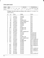
TABLE OF CONTENTS
Chapter 1 INTRODUCTION
Printer components
Summary of printer features
Font style example
Chapter 2 SETTING UP THE PRINTER
Printer placement
Unpacking and inspection
Setting up
Installing the platen knob
Installing the ribbon cartridge
Installing the paper guide
Connecting the interface cable
Configuring your software for the printer
Chapter 3 PAPER INSTALLATION AND USE
Selection of paper
Adjusting the printing gap
Loading single sheets
Loading and parking fanfold forms
Loading the paper
Paper parking
Paper unparking ‘“
Chapter 4 CONTROL PANEL OPERATIONS
Button and indicator functions
ON LINE
PAPER FEED
SET/EJECT
PITCH
FONT
Switchcombination functions
Form feed
Top of form
Forward micro-feed
Reverse micro-feed
I
2
4
6
7
7
8
9
9
10
13
13
15
17
17
18
19
22
23
25
26
27
27
28
29
29
30
30
31
31
32
32
32
Changing the auto loading position
Clearing the buffer/All reset
Save macro definition
Power-up functions
Short test mode
Long test mode
Print area test mode
Pitch lock mode
Font lock mode
Font and Pitch lock mode
Dot adjustment mode
Hexadecimal dump
Conditions indicated by beep tones
Chapter 5 DEFAULT SETTINGS - EDS MODE
How to set the EDS mode
Functions of the EDS settings
Chapter 6 TROUBLESHOOTING
Maintenance
Chapter 7 OPTIONAL ACCESSORIES
Automatic Sheet Feeder
Setting up
Loading paper
Pull Tractor Unit
Setting up
Loading paper
Serial Interface Cartridge
DIP switch functions on the serial interface cartridge
Chapter 8 PRINTER CONTROL COMMANDS
Font control commands
Character set commands
Character size and pitch commands
32
33
34
35
35
36
37
37
37
37
38
39
40
41
41
42
47
52
53
53
54
57
59
60
61
63
64
65
66
71
74
Vertical position commands
Horizontal position commands
Graphics commands
Download character commwlds
Other printer ct)mnmnds
Chapter 9 DOWNLOAD CHARACTERS
Det’iningyour own characters with stand~tr~imode
Assigning the character’data
Assigning it v:due of character space
S~tmpleprogram
Definin: ~our own chmacters with IBM mode
Assigning the downlo:td character set
Assigning the uhar:wtcr dot pattern
Assigning the Index Table data
sample
pr”ogl”m
Chapter 10 MS-DOS AND YOUR PRINrl’ER
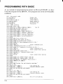
Programming the printer with DOS commands
Programming with BASIC
80
86
90
94
97
I01
101
10?
103
104
106
106
107
108
110
113
I 13
I 16
Chapter 11 REFERENCE
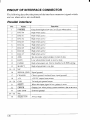
Specifications
Pinout of interface connector
Parallel interface
Serial interface
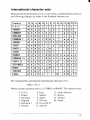
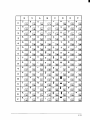
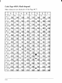
Character sets
Standard character set #2
International character sets
IBM character set #2
Character set #l
IBM special charircter set
INDEX
141
COMMAND SUMMARY
145
chapter 1
INTRODUCTION
This printer has a full complement of features, making it an excellent partner
for a personal computer. It supports the Epson/IBM printer commands and
character sets, enabling it to print just about anything your computer can
generate, both text and graphics.
The selection of paper you can use is as varied as the types of document you
can produce. This printer accepts any of the following kinds of paper:
Single sheets (cut forms) and stationery
Fanfold forms (continuous forms)
Multi-part forms (up to 3-ply)
Preprinted forms
●
●
●
●
This Multi-font printer has the following resident (internal) fonts:
Draft
Roman
Sanserif
Courier
Prestige
Script
●
●
●
●
●
●
The control panel has five but[ons and eleven indicators. The indicator
display and beep tones provide immediate, easy-to-understand feedback
when you press the buttons on the control panel.
The five buttons can operate in combinations to perform a surprising variety
of functions, including saving a micro.
An additional useful feature is the ability to switch easily between printing
on fanfold paper and printing on single sheets. A simple control panel
operation lets you “park” the fanfold paper, so that you do not have to remove
the fanfold paper from the printer. When you want to resume printing on the
fanfold paper, you can simply “unpark” it.
To get acquainted with the printer’s components and capabilities, refer to the
information on the pages that follow.
1
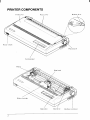
PRINTER COMPONENTS
Front cover
Release lever
Rear cover
Controi panel
Bitil roller
~
Bail lever
Interface connector
Component
Description
Paper guide
Aligns single sheets (cut forms) to help the printer
detect when paper is inserted.
Release lever
I Releases pressure on the paper. This lever must be
I
back for cut forms (~), and forward for fanfold
forms ( ~).
Front cover
Protects the print head and other internal components of your printer.
Rear cover
Protects the tractor feed unit and separates incoming and outgoing fanfold forms.
Entry slot
For inserting single sheets of paper.
Control panel
Indicates printer status and makes control of
printer functions simple and convenient.
Power switch
Switches power on or off.
Platen knob
For advancing the paper manually.
Interface connector
Connects the computer to the printer.
Print head
Has a high resolution dot matrix (24-wire) composition for outstanding print quality.
Ribbon cartridge
Contains the printer ribbon.
Adjustinent lever
Controls print darkness by adjusting for the
thickness of forms being printed.
Tractors
Control the movement of fanfold forms.
Clamp lever
Clamps the tractor in place.
Bail lever
Opens and closes the paper bail which holds the
paper against the platen.
3
I
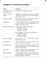
SUMMARY OF PRINTER FEATURES
Feature
Function
Dot matrix (24-wire)
impact printing
Draft and Letter-Quality printing.
Extensive software
support
The printer is compatible with the Epson and IBM
standards, and works with any software that supports those printers.
Multi-font support
This printer includes Draft, Roman, Sanserif,
Courier, Prestige, and Script fonts.
Carriage size
A wide carriage that prints on cut forms up to 420
mm (16.5 inches) wide and fanfold forms up to
406 mm (16 inches) wide.
Multi-speed printing
In Draft mode, prints at speeds up to:
300 CPS in 15 pitch
240 CPS in 12 pitch
200 CPS in 10 pitch
●
●
●
In Letter-Quality mode, prints at speeds up to:
100 CPS in 15 pitch
80 CPS in 12 pitch
67 CPS in 10 pitch.
●
●
●
Character spacing
Prints in 10, 12, 15, 17, and 20 CPI, as well as
proportional spacing.
Control panel
Button control for fonts, pitches, paper movement, and paper park functions.
Font/Pitch Lock
Ignores font and pitch selections sent from your
computer, and’stays on the font and pitch selected
from the control panel.
Quiet mode
Reduces printing noise by approximately 50%.
However, printing speed is also reduced.
Graphics printing
Standard graphics printing with resolution of up
to 360x 360 dots per square inch. It also supports
the NEC graphics commands.
4
Feature
Function
Paper parking
Parks fanfold paper. You can print on cut sheet
paper without unloading the fanfold forms.
Print styles
Highlighting capability with the
phasis styles:
Double-high Double-strike
Emphasized Italics
Shadow
Overlining
Underlining.
Superscript
●
●
●
●
●
●
●
●
●
●
●
following emDouble-wide
Outline
Subscript
Tear off function
Fanfold forms can be removed without advancing
blank forms.
Multi-part forms
up to three-part forms.
I Prints
the printer ribbon.
I Contains
Electronic DIP Switch (EDS) mode allows you to
Ribbon cartridge
EDS mode
easily change the default settings of your printer
to match your system and software needs.
5
FONT STYLE EXAMPLE
The following example shows the many font styles your printer can print.
Resident fonts are:
Draft
characters
,
Roman characters,
Sanserif
characters,
Courier characters,
Prestige characters,
sc.Jt.Lptdmmetwm.
Print pitches are:
Pica pitch (10 CPI),
Elitepitch (12 CPI),
Semi-condensed pitch
(15 CPI),
Condensed
picapitch(17CPI),
Condettsed
elite
pitch
(20CPI),
- Normal proportional,
Condettsed
proportiottal
Double-height,
width.
Doub
TX-*P1
1 e
e=
widtilm=
Various line and character spacings:
//’4%
G
D
gB
l!”
W
Other features:
Oumnm) , s-m,
OumLmm)mm ssu?mwm,
Emphasized,
Double-strike, Italics,
! Werllnlng,
Underlining, ~
StJF’ERscRIPTand SUBSCRIPT,
Download characters: ‘stttti~~~s~tsss
Dot graphics:
Az!!Q!!D
6
chapter2
SETTING UP THE PRINTER
This chapter describes the following procedures for setting up your new
printer. If you have optional accessories. refer to Chapter 7 after setting up
the printer.
.
.
.
.
.
.
Printer placement
Unpacking the printer
Installing the platen knob
Installing the ribbon cartridge
Connecting the printer to your computer
Configuring your software for the printer
PRtNTER PLACEMENT
Before you start setting up your printer, make sure that you have a suitable
place on which to locate it. By “a suitable place”, we mean:
. A firm, level surface which is fairly vibration-free
. Away from excessive heat (such as direct sunlight, heaters, etc)
. Away from excessive humidity
. Away’from excessive dust
. A“steady power supply that is not subject to power surges should be
connected to the printer.
For example. do not connect the printer to the same circuit as a large, noiseproducing appliance such as a refrigerator or an air conditioner.
●
✎
Make sure the line voltage is the voltage specified on the printer’s
identification plate.
If you are connecting your printer with a parallel interface, make sure that
the cable is within 2m (6ft) of the printer. An RS-232 connection using the
optional IS-8XL interface cartridge can be made over longer distances.
7
I
UNPACKING AND INSPECTION
Now check each item in the box against Figure 2-1 to make sure that you have
everything (there should be five items).
If any of these items are missing, contact your supplier.
Figure Z-l. Check to make sure you have all five items: 1) Printer, 2) Paper guide, 3) Platen knob, 4) Ribbon
cafiridge, and 5) User’s manual.
The optional accessories which you may have ordered with your printer are:
●
●
●
Serial interface cartridge (IS-8XL)
Automatic sheet feeder (SF-15DJ)
Pull tractor unit (PT-15XJ)
For details of the optional accessories, refer to Chapter 7.
8
SETTING UP
Place the printer in the desired location, and remove all packing material
from the printer. This packing material is intended to prevent damage to the
printer while in transit.
You will want to keep all the packing material, along with the printer carton,
in case you have to move the printer to a new location.
Installing the platen knob
The platen knob is packed into a recess of the packing material which held
your printer inside the printer carton. Be careful to remove the knob before
disposing of the package.
Mount the knob on the platen shaft, which is located on the right-hand side
of the printer. Rotate the knob on the shaft before pushing the knob fully into
position.
Figure 2-2. Installing the platen knob
9
I
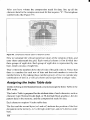
Installing the ribbon cartridge
Now install the ribbon by the following procedure.
1. Remove the front cover by lifting the front (using the two grips at the
sides), and pulling towards you.
Figure 2-3. Remove the front cover to install the ribbon cartridge.
L.
slack in the ribbon bytuming the tension knob on the ribbon
cartridge clockwise as shown by the arrow.
T&e
up the
Figure2-4. Take up the slack in the ribbon by turning the tension knob on the ribbon cartridge.
10
3. Guide the ribbon between the print head and the silver print head shield,
making certain that the spindles on the cartridge holder fit into the sockets
on the cartridge itself.
Figure 2-5. Install the ribbon cartridge
4. Make sure that the ribbon is positioned between the print head and the
print head shield as shown in Figure 2-5.
5. Take up the slack in the ribbon again by turning the tension knob.
Figure 2-6. Make sure that the ribbon is positioned correctly.
11
I
6. Hold the front cover upright and engage the tabs at the back. Then swing
the front edge down until the cover is closed.
Figure 2-7. Swing down the front of the front cover after inserting the tabs into the slots of the printer case.
Leave the front cover closed during normal operation. The cover keeps out
dust and dirt and reduces the printer’s operating noise. Open the cover only
to change the ,ribbon or make an adjustment.
12
Installing the paper guide
Follow the procedure below to install the paper guide:
1. Insert the two slots on either side of the paper guide into the two tabs on
the rear cover, as shown in Figure 2-8.
Figure 2-8. Install the paper guide,
2. Place thepaperguidehorizontally whenusingfanfold paper, orvertically
when using single sheets.
Connecting the interface cable
The printer and computer are connected by a cable along which the computer
transmits the documents that you want to print. A cable is not supplied as
standard equipmemt with this printer. There are two sorts of cable that you
can use: a standard 36-pin Centronics parallel cable or the serial cable that
you can purchase as an option with the printer.
Connecting the printer to a computer using a parallel cable is generally
simpler; however, the length of the parallel cable should not be more than 6
feet, otherwise the transfer of information between your computer and the
printer may be impaired. A serial connection can, for all practical purposes,
be as long as you 1ike,but is a little more complicated to set up. Buy the type
of cable which will best suit your needs.
If you need to connect to a serial port, use the optional SeriaI interface
cartridge, IS-8XL.
13
The parallel cable which you can use has a 25-pin D-type plug at one end, and
a 36-pin Centronics connector at the other.
Follow the procedure below to connect the interface cable:
1. Turn off the power switch on both the printer and the computer.
2. Plug the cable’s Centronics connector into the socket on the side of the
printer as shown in Figure 2-9.
Make sure that you press the plug into the interface connector.
I
+“ //” \EsY Ll
Figure 2-9. Connect the interface cable.
3. Move both clips inside the extended prongs on the sides of the plug until
you hear a click.
Figure 2-70. Move the clips until you hear a click.
4. Plug the 25-way plug into the parallel socket onyourcomputer. This will
probably be Iabelled “Printer”, “Paral]el”, “PRN”, “LpTl” or
similar.
14
something
!
Configuring your software for the printer
Most application software programs let you specify the type of printer you
are using so that the software can take full advantage of the printer’s features.
Many of these software packages provide an installation or setup program
that presents a list of printers.
This printer is preset to emulate the Epson printer commands. If you want to
emulate the IBM printer commands, you can select IBM with the Electronic
DIP Switch (EDS) mode.
Choose one of the following (in the order of preference) according to your
selected Emulation mode:
#
1
2
3
4
5
Standard (Epson) mode
Star NX-241511
Star NX-2415
Star NB24- 15
Epson LQ-106O
Epson LQ- 1050
IBM mode
Proprinter XL24E
Proprinter XL24
If your software package does not mention printers by name, but asks instead
what features your printer is capable of, the most common questions are:
“Can your printer perform a backspace?” and “Can it do a hardware form
feed?” you should answer “Yes” to both these questions.
Make sure that the Electronic DIP Switch (EDS) is set for the correct printer
emulation, and that you have also selected the appropriate character set.
(Refer to Chapter 5 for detailed information on the EDS mode.)
NOTE: If you are in doubt about the configuration of your application
software, seek expert advice. Your software supplier will probably
be your most qualified reference.
15
16
chapter3
PAPER INSTALLATION AND USE
This chapter describes instructions for printing such as selecting paper types,
adjusting the printing gap, and installing paper.
SELECTION OF PAPER
You can use any of the following types of paper with your printer: single
sheets, fanfold paper and multi-part forms.
Single sheets (cut forms) and stationery
Single sheets are simply individual, unconnected pieces of paper, and are
also sometimes referred to as cut sheets.
Up to fifty single sheets can be stacked and automatically fed into the
printer by using the optional Automatic Sheet Feeder (SF-15DJ).
Fanfold forms
Fanfold forms are sheets of paper joined with perforations. Fanfold forms
usually have a column of holes punched into each edge which enables the
printer to grip the paper as it feeds it through. Fanfold paper is also
sometimes referred to as computer paper, continuous forms or sprocket
forms.
You can feed the fanfold forms from the rear of the printeras standard. You
can aim use the optional Pull tractor unit (PT- 15XJ)to feed fanfold paper.
Printing on or near the perforations of continuous fanfold forms may
reduce printing quality, misalign the fanfold forms, or cause a paper jam.
Multi-part forms
Multi-part forms consist of several sheets, one on top of another, enabling
several copies to be made simultaneously. Multi-part forms may bejoined
together, as fanfold stationery. If you want to use multi-part forms, use the
type that has both side edges glued together. Do not use forms that have
more than three parts.
It is recommended that you load multi-part forms using the optional Pull
tractor unit.
●
✎
✎
Figure 3-1 shows the recommended print area for each type of paper.
17
Single sheets
Fanfold forms
5
Figure 3-1. Recommended print area for acceptable types of paper.
ADJUSTING THE PRINTING GAP
Paper comes in different weights, normally quoted in gsm (grams per square
meter). Typical figures are 80 gsm and 100 gsm. Heavier paper is thicker.
Also, multi-part forms are generally thicker than single sheets or ordinary
fanfold paper.
The distance between the print head and the platen can be adjusted to suit the
paper thickness. The adjustment lever is located inside the printer’s main
body, at the right-hand end of the platen. There are five settings. Push the
lever up to narrow the gap between the print head and the platen, and down
to widen the gap. The top position is referred to as position 1,and the lowest
position as position 5. Position 2 is the one most suited to single sheets.
Figure 3-2. Location of the adjustment lever.
18
It is a good idea to try out different settings in order to ascertain which setting
gives the best results in terms of print quality.
NOTE: Printing with an inappropriate gap may drastically shorten the life
of the print head.
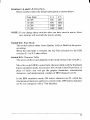
The table below gives recommended settings:
‘aPer ‘J’pe
Weight(g/mz) Thickness(mm) Recommended
(Total)
Lever position
(Each sheet)
Single
52 to 90
0.07too.
12
2 or 3
2-ply
40 to 52
0.12 to 0.14
2 or 3
3-ply
40 to 52
O.18to0.21
3 or 4
LOADING SINGLE SHEETS
This section will take you through the procedure for loading single sheets of
paper. If you are using the optional Automatic Sheet Feeder (SF- 15DJ),refer
to Chapter 7.
The paper path for cut forms is shown in Figure 3-3.
I
Figure 3-3. Paper path for cut forms
19
I
1. Raise the paper guide vertically on the rear cover..
Figure 3-4, Raise the paper guide vertically
‘7
-.
3.
4.
5.
6
20
Turn ON the power at the switch located at the front of the printer. The
printer will beep, indicating that there is no paper in position for printing.
The POWER indicator will also flash to confirm this.
Make sure that the release lever is at rear position (k).
If fanfold paper is already mounted in the printer, press the(SET/EJEC@
button to park the paper in the off-line state, then move the release lever
toward the rear of the printer.
Adjust the left paper guide to the desired left position by moving it
horizontally in either direction.
Adjust the right paper guide to accommodate the width of the paper.
The guides should be adjusted to restrict the amount of horizontal play
while allowing the paper to slide up and down freely between the two
paper guides. The ideal distance between paper ream and paper guides
is 0.25 mm (0.01”) on both sides at the narrowest part of the paper guides.
Place a single sheet between the guides, facing the side on which you
want to print towards the back of the printer. Gently push the paper down
in the guides until you feel it stop.
Figure 2?-5.Place a single sheet between the guides.
7. Now press the(SET/EJEC~ button. Thepaper will be fed into the printer
and adjusted past the print head to a position ready for printing.
8. If you want to set the paper to a different position, set the printer off-line
by pressing the (ONLINE) button, then set the paper by using the microfeed function. (For details, refer to Chapter 4.)
Now you are ready to start printing.
21
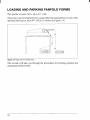
LOADING AND PARKING FANFOLD FORMS
This printer accepts forms up to 16” wide.
The printer can feed fanfold forms using either the standard tractor unit or the
optional Pull tractor unit (PT- 15XJ), as shown in Figure 3-6.
—.
Figure 3-6. Paper path tor tantold tOrmS.
This section will take you through the procedures for loading, parking and
unparking fanfold forms.
22
Loading the paper
If you are going to load the paper with the optional Pull tractor unit, refer to
Chapter 7.
1. Place a stack of fanfold paper behind and at least one page-length below
the printer.
2. Turn the printer’s power OFF.
3. Push the release lever forward. This has the effect of releasing the paper
from the platen roller, and engaging the tractor feed.
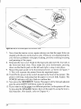
4. Remove the rear cover. Grip it by its rear edge and lift upwards and
backwards as in Figure 3-7.
I
Figure 3-7. Remove the rear cover.
5. With the tractor covers open, mount the paperby aligning holes with the
pins on the tractor unit.
6. Adjust the spacing of the tractor units by sliding them along the bar, using
the clamp lever at the back of each unit to release them and lock them in
position. The unit is released when the clamp lever is down and locked
when the clamp lever is up.
23
Tractor cober
CIamp lever
Figure 3-8. Mount the fanfold paper over the tractor units.
7. Now close the tractor covers, again making sure that the paper holes are
aligned with the pins on the tractor units. If they are not aligned properly,
you will have problems with paper feeding, possibly resulting in tearing
and jamming of the paper.
8. Remount the rear cover. Hold it tilted upward and insert the four tabs at
the front into their slots. Then rotate the cover downwards, pressing
down on the thumb pads on the left and right to snap it into place.
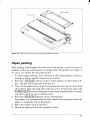
9. Mount the paper guide in the horizontal position, as shown in Figure 39. This will separate the printed from the unprinted paper.
10.Turn ON the power at the switch located at the front of the printer. The
printer will beep, indicating that the paper is not yet fully loaded. The
POWER indicator will also flash to confirm this.
11.Now press the (SET/EJECO button. The paper will be fed and adjusted
past the print head to a position ready for printing.
12.If you want to set the paper to a different position, set the printer off-line
by pressing the (ON LINE) button, then set the paper by using the microfeed function. (For details, refer to Chapter 4.)
24
Figure 3-9. Close the rear cover, then set the paper guide horizontally
Paper parking
After loading fanfold paper from the rear of the printer, you do not have to
unload it when you want to print on a single sheet. The printer will “park” it
for you if you follow the procedure below.
1. To begin paper parking, start with power ON, fanfold paper loaded in
printing position, and the release lever forward.
2. Press the (ON LINE) button on the control panel to set the printer offline. The ON LINE indicator will turn off.
3. Tear off the printed form at the last perforation, leaving not more than
about half a page showing above the top cover. If necessary, press the
@APERFEED button to feed paper forward until a perforation is located
just above the front cover, and tear there.
4. Press the (SET/EJECT button on the control panel.
The printer will automatically feed the fanfold form backward until the
paper is completely free of the platen.
5. Move the release lever to the back.
6. Mount the paper guide in the upright position.
25
I
Now you can load single sheets, as explained previously. The fanfold paper
remains parked at the back of the printer.
NOTE: You cannot park the fanfold paper if you have loaded it with the
optional pull tractor unit.
Paper unparking
When you want to resume using fanfold paper, the procedure is as follows.
1.
2.
3.
4.
Remove all single sheets from the printer.
Mount the paper guide in the horizontal position.
Move the release lever to the front.
Press the($ET/EJECT)button. The printer will automatically feed the
parked fanfold paper back into position for printing.
NOTE: The printer beeps intermittently if you move the release lever while
the paper is loaded.
26
chapter 4
CONTROL PANEL OPERATIONS
The control panel buttons can be pressed individually to perform the
operations indicated by their names. Other functions can be achieved by
pressing the control panel buttons in combination, or by holding these
buttons down when you turn the printer’s power on.
This chapter explains all the button and indicator functions.
Pause printing
Feed paper (fast and slow, forward and reverse)
Park fanfold forms
Set the top-of-form position
Select the print pitch
Select a font
Save macro definition
Clear the printer’s buffer
Print test patterns
Prevent software from changing the panel pitch and font selections
Adjust the print alignment for bi-directional printing
Print a hexadecimal dump
●
●
●
●
●
●
●
●
●
●
●
●
BUITON AND INDICATOR FUNCTIONS
The printer is equipped with five buttons on the control panel. From left to
right they are m,
m,
(SETEJECT),@A1’ERFEE@and
(ONLINE].
The following is a brief guide to the buttons and indicators on the control
panel.
Figure 4-7. Control panel.
27
I
ON LINE
The(ON LINE) button setsthe printer on-line and off-line. The status changes
each time you press the button.
When the printer is on-line, it can receive and print data from the computer.
This status is indicated by the ON LINE indicator being lit. When the printer
is off-line, it stops printing and sends the computer a signal indicating that
it cannot accept data.
The printer powers up in the on-line status when paper is loaded. If paper is
not loaded, the printer powers up off-line with the POWER indicator
blinking. When you load paper, the printer goes on-line.
You will want to press the(ON LINE] button:
c Before and after any other panel operation
The other panel buttons operate in the off-line state. Press the ON LINE)
button to go off-line. After performing the panel operation(s), press the
(ON LINE) button again to go back on-line.
●
To pause during printing
If you press the (ON LINE) button during printing, the printer stops printing
and goes off-line, allowing you to check the printout or change a control
panel setting. Printing resumes when you press the (ON LINE) button again
to go back on-line.
●
To cut fanfold forms at the end of printing
When you hold down the ON LINE) button and press the (PAPER FEEO
button down for one second with the fanfold forms fed through by the
standard tractor unit, the printer goes off-line, then the printer feeds the paper
forward approximately two inches. This allows you to cut it off just below
the last line printed.
When you press the (ONLINE) button again to go back on-line, the paper
feeds backward stopping where you left off.
NOTE: This function is available only when the buffer is empty.
28
I
PAPER FEED
If you press and release this button while off-line, the paper will feed forward
one line. If you hold the button down, the printer will perform consecutive
line feeds.
If you also press the (ONLINE) button while you are line-feeding, the paper
will feed automatically to the top of the next page. This is explained later.
If you press the (PAPER FEED) button while on-line, this will alternately
illuminate andextinguishthe QUIET indicator. When in Quiet mode with the
QUIET indicator illuminated, the printer will print slightly slower, but at a
reduced noise level.
SET/EJECT
NOTE: This button has no effect if the Pull tractor unit is used.
Pressing this button causes the printer to begin paper loading if the paper has
not loaded while in the off-line state.
If the paper has been loaded, pressing this button results in different functions
depending on the position of the release lever.
If the release lever is facing toward the rear of the printer for cut forms (~),
pressing this button ejects the paper.
If the release lever is facing toward the front of the printer for fanfold forms
( k), pressing
this button parks the forms.
I
PITCH
This button allows you to select the printing pitch. Remember that the printer
must be off-line for you to do this. Successive presses of this button will
illuminate (and select) the following options in order:
Pitch
Pica (10 CPI)
Elite(12 CPI)
Semi-condensed(15 CPI)
Condensedpica (17 CPI)
Condensedelite (20 CPI)
Super-condensed(24 CP1)
Indicator(s)
10CPI
10CPI, 15CPI
15CPI
10CPI,COND
10CPI, 15CPI,COND
15CPI, COND (IBM only)
Proportional
Condensed proportional
PROP
PROP, COND
FONT
This button selects the font to be printed. Roman font is selected at powerup unless the default settings are changed. To change the font, set the printer
off-line, then press the(~T)
button repeatedly until the indicators beside
the desired selection illuminate. The selections cycle in the following order:
30
Font
Indicators
Draft
DRAFT
SWITCH COMBINATION FUNCTIONS
Several additional functions can be achieved by pressing the control panel
buttons in combinations.
Top of Form
w
-,
Roman
~Sans.rif
= Courier
9
I
~~~~
—
& SlxLpt
-PROP
-
POWER
Mlcrm !=EEO
~ 42CPI
m 15CPI
7
SET/~EJ:CT
PITCH
—
CDND
ALT
—
A
-O+JUSI
PAPER FEED
——
CLEAR
MACIWJ
●
▼
Save Macro
I
m
L ON UNE
BufferClear/AllReset
J
)
tA
FormFeed
—
Figure 4-2. Switch combination functions of control panel
Form feed
If you are using cut forms, this operation ejects the current page. If you are
using fanfold forms, it feeds to the top of the next page.
1. Press the (ON LINE) button to set the printer off-line.
2. Press the(PAPER FEED) button and hold it down. The printer will start
performing successive line feeds.
3. While holding the (PAPER FEED) button down, press the (ON LIN@
button, then release both buttons at the same time. The printer will
smoothly eject the current page.
I
Top of form
When you power on the printer, the top-of-form position is automatically set
to the current position. If this is not where you want the top of the page to be,
you can change the top-of-form position as follows:
1. Press the ON LINE) button to set the printer off-line.
2. Press and hold down the (ON LINE) button.
3. Whi)eholdingthe(ON LINE)buttondown, press the@~H>button, then
release both buttons at the same time. The printer will beep to indicate
that the top-of-form position has been set.
Forward micro-feed
For fine alignment, you can feed the paper forward in very small increments
as follows:
1. Press the (ON LINE) button to set the printer off-line.
2. Press the (ON LINE] button again and hold it down.
3. While holding the (ON LINE)button down, press the (PAPER FEEO
button. The paper will start advancing in a series of small steps
When you want to stop, release both buttons.
Reverse micro-feed
You can also feed the paper in small increments in reverse, to return to a
higher position on the same page.
1. Press the (ON LINE) button to set the printer off-line.
2. Press the (ON LINE) button again and hold it down.
3. While holding the (O~E)
button down, press the (SET/EJECT)
button. The paper will start moving backwards in a series of small steps.
When you want to stop, release both buttons.
Changing the auto loading position
Normally, the printer automatically loads the paper one line from the top
edge. If you want to change this value, follow this procedure:
1. Load the paper by pressing the @ET/EJECT) button.
2. Change the print position using the micro feed function.
3. After you setup the desired position, press the (ONLINE) button to save
the value.
32
This position remains valid until you power off the printer. If you want to
retain this position even after you turn off the power, store it using the Macro
Definition function, which is described later.
Note that you can only change this value immediately after loading paper. If
you feed paper, you cannot change the auto loading value.
Clearing the buffer/All reset
The printer stores received data in a large memory buffer. This creates a
problem when you want to abandon a printingjob and restart: the printer may
be holding more data in its buffer than it has actually printed, and this
unprinted data must be cleared out before restarting. Turning power off is one
way to clear the buffer, but there is another way:
1. Haltthe printing program onthe computer. If printing stops immediately,
the buffer is clear and the rest of this procedure is unnecessary. If printing
does not stop, continue as follows:
2. Press the (ON LINIij)button to set the printer off-line. Printing will now
stop, but there may be data remaining in the buffer.
3. Press and hold down the(m)
button.
4. While pressing the (-T)
button down, press and hold down the
(ON LINE)button. Continue holding these two buttons down and you will
hear a beep tone signaling that the buffer has been cleared. If you hold
these buttons down longer, you will hear three beep tones and the printer
has been initialized to the power-on default settings.
5. Release these buttons, make any necessary control panel settings, then
set the printer back on-line.
It is essential to stop the printing program on the computer before you go offline. Otherwise, when you go back on-line the computer will start sending
data again and the printer will continue printing, with data missing from
when the buffer was cleared.
33
I
Save Macro Definition
You can save the current settings to the printer for later use by the following
procedure:
1. Press the (ON LINE) button to set the printer off-line.
2. Press the(_T)
button and hold it down.
3. While holding thebutton down, press the (-)
button and
hold them down until you hear a beep tone.
4. Release both buttons at the same time after this beep tone to save the
current setting.
If you release these buttons after three beep tones, the macro has been
cleared.
NOTE: You can store the following settings by this procedure.
. Current Font
Current Pitch
Current auto-loading amount for cut forms
Current auto-loading amount for fanfold forms
Current auto-loading amount in ASF mode
●
●
●
●
34
POWER-UP FUNCTIONS
In addition to their normal functions, all of the control panel buttons perform
“special” functions if you hold them down while switching the power button
on.
DotAdjustment
I=
m 10CPI
L 12CPI
m 15CPI
DWAF7
= Roman
~Sanserif
- Courier
~Prestige
~~N-f
mPRoP
n
wSuL.Lpt
ALT
Font Lock
PtTCH
Omu
-
MICROFEED
+
i
SET//El~CT
-GUET
PAPER FEED
POWER
A
I
L ON LINE
~c=)
COND
CLEAR
MACRG
1
I
Pitch
Lock
Font & Pitch Lock
Print Area I
Long Test
Test
I
Hex.Dump
Short Test
Figure 4-3. Power-up functions of control panel.
Short test mode
If the printer is turned on while the (ON LINE) button is pressed, the printer
will enter the short self-test mode. The printer will print the version number
of the printer’s ROM, followed by seven lines of the character set.
Each line will be offset by one character from the one before it. The final
result will be something like Figure 4-4.
***v~~XAX—-***
!“#swtJ*+,-.
/0123456789:
: <=>7@ABCDEFGHIJKLMNOpQRsTUv*xyz [\] ‘–’ abcdefshi jklmnOp~
!“#$%& ()*+. -, /0 123456789: ; <-> ?@ABCDEFGHIJKLMmWRsTuv*xyz[/1 ‘–’ abcdefshi jklmnOpql
‘“#$x&I()a+, –. /0 1234S6789:: <=>?@ABcDEFGHIJK~NoWRsTuvwxyz
[\] ‘–’ abcdefghi jklmnOpqr!
#$%& ()*+, -. /01 23456789:;<=>?@ABCDEFGHIJKLMNOPQRs’Tuvwxyz
[\]‘–’abcdefshi jklmnopqrsj
$%& ()*+, -./0 123456789: :<=>?@ABCDEFGHIJKLMNOPQf?
sTUvwXyz[\l“–’abcdefshi jklmnopqrstl
%& ()*+, –. /Ot 23456789:;<=>?f3ABCDEFGH
IJKLMNOPQRs’fUv*
xyz[\] ‘–’ abcdefghi jklmnoprtrstu,
& ()*+, - ./0 123456789: :<=>?@A8CDEFGHI
JKLMNoPQRsTuv*xyz
[\ ] “–’ abcdefghi jklmnOpqrstuvl
I
Figure 4-4. Short self-test.
Since the self-test prints across the full width of the carriage, it is recommended that the printer is loaded with the widest paper possible to avoid
damage to the print head and/or platen.
35
I
Long test mode
If the printer is turned on while the (PAPER FEED) button is pressed, the
printer will enter the long self-test mode. The printer will print the version
number of the printer’s ROM, the current Electronic DIP Switch (EDS)
settings and the current Dot Adjustment settings, followed by the entire
character set printed in each font and pitch available.
The test repeats endlessly, so you must turn the power off to stop it.
...
V,,
,.,
4’0
Figure 4-5. Long self-test.
Since the self-test prints across the full width of the carriage, it is recommended that the printer is loaded with the widest paper possible to avoid
damage to the print head and/or platen. In addition, the total number of lines
printed is considerable, more than can be accommodated on a single sheet,
so fanfold paper is recommended for this test.
36
I
Print area test mode
By holding the (SET/EJECT) button down during power-up, the printer will
enter the print area test mode. You can find how many lines on your paper are
available for printing with l/6-inch line feeding. The printer will print the
first line message on the paper, then print the last line message after feeding
to the bottom of the page.
If you have loaded fanfold paper, only the first line message is printed.
Pitch lock mode
By holding the(m)
button down during power-up, the print pitch can
only be selected from the control panel, This prevents software interference.
You will hear an acknowledging beep as power comes on.
After the beep tone, you can set the printer off-line, select a print pitch, then
return to the on-line state and start printing. The pitch you selected will not
be reset or otherwise changed by any commands your software may issue.
Font lock mode
By holding the(m)
button down during power-up, fonts can only be
selected from the control panel. This prevents software interference. There
will bean acknowledging beep tone. After this you can setthe printer off-line,
select a font, then return to the on-line state and begin printing. The selected
font will not be changed by any commands your software may issue.
Font and Pitch lock mode
If you want to protect both the font and pitch settings from software changes,
press both the (n)
and(m)
buttons during power-up. There will be
two acknowledging beep tones.
Pressing these buttons during power-up does not prevent you from making
any number of changes later from the control panel.
Dot adjustment mode
This mode is used to adjust the vertical alignment of text and graphics on
successive bi-directional passes.
After a period of time, your printer may work itself out of alignment on left
and right printing passes. This malalignment appears most visibly during
graphics printing. This mode will probably be used very rarely.
1. Turn the printer off and then turn it on again while holding down the
(SET/EJECT) and (ON LINE) buttons. The printer will print something
like the following:
xxx
DOT
ADJUS’1’MENT
**8
1111111111111111111111111111111111111111
o :
LQ
SETTING
2. The printer will feed the paper forwards and backwards during this
operation, allowing you to view the paper for optimum alignment.
3. Toadjust the printing, usethe(SET/EJECT) and(PAPERFEED>buttons.
The (SET/EJECT) button will move the second pass to the left. The
(PAPER FEED) button will move the second pass to the right.
xx8
LQ
(~
(
PAPER FEED
LQ
*LQ
DOT
ADJUSTMENT
X8*
1111111111111111111111111111111111111111
o:
-1
SETTING
:
ltlllllll!lll
1111111111111
11111
1!l!lll!
!llll!!
111111
11111111111
11111
(11111!1
1111
o : I I I I ‘1I I I I I I I I I I I I I I I I I I I I I I I I I I I I I I I I I I I
4. When the two passes are aligned with each other to form one continuous
line, the bi-directional alignment test is completed.
5. To change the mode for which the bi-directional adjustment is performed, press the [ON LINE) button. This will cycle through “LQ”,
“DRAFT”, “DRAIT COND”, and “’GRAPHICS”.
Repeat the process for all print modes.
6. To exit from this mode, press the(~~
38
button.
8**
DOT
ADJUSTMENT
LQ
( SET/EJECT
111111111111111111111111111111111111
o:
-1
‘LQ
:
(PAPER FEED
(
ONLINE
(PAPER FEED
;/ );/)
/////
!,(,
1111111111111
,11111111
11141111111111
!1111[1
11!
IH II
1
11111!
‘iLQ
0:
1111111111111111111111111
Hlllllllllllll
‘DRAFT
o:
1111111111111111111111111
111111111111111
%RAFT
+1 :
IIl!lltlllll
111111{111!1!
1111111111111
1111111111111
SET/EJECT
‘DRAFT
( ONLINE *DRAFT
COND
( ONLINE ‘GRAPHICS
(
=
SJjl’TI).J(J
***
!1!1!1(111!11
11!111!1111111
II
1111111111111111111111111
111111111111111
O : 1111111111111111111111111
111111111111111
o:
o:
1111111111111111111111111
111111111111111
9
*$$ END *t*
Hexadecimal dump
This feature isusefulforprogrammers whoaredebuggingprintingprograms
and wantto seethe actual codes the printer is receiving. (Some computers
change the codes the programmer intended.)
Inthismode,all datareceived will beprintedinahexadecimal dumpforma~
ratherthan the control codes being actedon as command codes.
This mode is accessed by the following procedure:
1. While holding boththe (PAPER FEED) and(SET~JECT)buttons down,
turn power ON. A beep tone will be heard.
2. Begin printing. In place of the usual printout you will get a formatted
dump showing exactly what data the printer receives. Each line presents
sixteen characters, their hexadecimal codes to the left and printable
characters printed on the right.
3. At the end of the hexadecimal dump, set the printer off-line with the
(ON LINE) button. This is necessary to print the last line.
CONDITIONS INDICATED BY BEEP TONES
This section helps you identify the meanings of beep tones.
Meaning
Beep tone
Two-second tone
Printer detects an error condition.
Turn off the power switch and turn it on again.
Four short tones
sequence, twice
Printer is out of paper.
Short tone, once
●
●
●
Short tone, twice
✎
✎
Short tone, three times
✎
●
One-quarter tone
●
●
●
Buffer is cleared.
Top of form is set.
Quiet mode is selected.
Macro definition is selected.
Quiet mode is cancelled.
Macro definition is cancelled.
Printer is reset.
Hexadecimal mode is selected.
Pitch lock mode is selected.
Font lock mode is selected.
One-quarter tone, twice Pitch and Font lock modes are selected at a time.
40
9
chapter5
DEFAULT SETTINGS-EDS MODE
From the control panel you can change the parameters that define how your
printer works. These parameters become your power-on settings. This
function is called the Electronic DIP Switch (EDS) mode.
HOW TO SET THE EDS MODE
The EDS mode in this printer has 16functions that you can set as the poweron default settings.
Turn the printer on while simultaneously holding down the (SET/EJECT)j
(PAPER FEED), and (ON LINE) buttons. You will hear an acknowledging
beep as power comes on. This indicates that you have entered the EDS mode.
In EDS mode, the buttons on the control panel are used as shown below in
Figure 5-1.
r-
t
Select Bank
II
Select Switch
,
&
Exit
Print
A
Change Setting
L
Figure 5-f. Button functions in the EDS mode
●
●
●
●
●
Use the(m)
button to select the Bank Letter.
Use the (-)
button to select the Switch Number.
The ON LINE indicator shows the current setting, ON or OFF.
Use the (ON LINE) button to change the settings.
Press the (PAPER FEEobutton to print the current settings.
Press the (SET/EJECT) button to save and exit the EDS mode.
41
I
FUNCTIONS OF THE EDS SETTINGS
The printer stores the parameters that you select from the control panel while
in the EDS mode.
A default is the setting that the printer will use if none is specifically selected
by a program. When you first turn on or later reset your printer, these default
settings will take effect.
By changing the settings, you can alter various printer functions to match
your specific requirements. The following table will help you choose the
proper settings.
nk-Switch Function
Bar
j ON
Standard/Epson
Emulation
A-z
I Enabled
AEC Mode
Input Buffer
A-3
RAM Usage
A-4
Automatic Sheet Feeder I Not installed
Disabled
A-5
Auto LF with CR
Bi-directiomd
B- I - Graphics Direction
Enabled
Paper-ou[
B-2
Type A
B-3
Printable Area
Leave ON
B-4
(Reserved)
Disabled
B-5
CR Centering
A-1
I OFF
I IBM
Disabled
Download buffer
\ Installed
Enabled
Uni-directional
Disabled
1 Type B
I Enabled
c-1
B
C.2
c-3
c-4
c-5
D-t
D-2
D-3
D-4
D-5
E-1
E-2
Page Length
1
I
I (See below)
Print Pitch
(See below)
Print Mode
Character Table
Standard mode
IBM mode
Code page or
International
Character Set
Letter Quality
Draft
Graphics
IBM #2
Italics
IBM #l
LQ Font Selection
(See below)
(See below)
E-3
E-4
(Reserved)
Leave ON
E-5
(Reserved)
Leave ON
NOTE: The default is ON for all functions at purchase except B-1 and B-3
which are set to the OFF position.
42
Switches A-1: Emulation
Select the mode compatible with your computer and software. In
standard mode the printer operates like the Epson LQ-106O. In IBM
mode it operates like the IBM Proprinter XL24E. The ON position
selects standard mode. The OFF position selects IBM mode.
Switch A-2: Auto Emulation Change (AEC) Mode
. This switch selects the Auto Emulation Change (AEC) mode.
When the AEC mode is enabled, the printer automatically judges the
Emulation which your application program uses.
Switch A-3: RAM usage
In order todownload characters this switch must be in the OFF position.
The printer then uses its RAM memory for storing character patterns
and provides only a one-line print buffer. If you leave this switch ON,
the printer uses its RAM memory as an input buffer, allowing the
computer to send faster than the printer prints.
Switch A-4: Automatic Sheet Feeder
When using the optional automatic sheet feeder (SF- 15DJ), move this
switch to the OFF position.
Otherwise leave it ON.
Switch A-5: Auto LF with CR
If you leave this switch at the ON position, a separate line-feed code is
required from your computer to obtain a line feed.
If you move this switch to the OFF position, the printer performs both
a carriage return and line feed each time it receives a carriage-return
code.
Most computer systems send a line feed code, or both a carriage return
and line feed, at the end of each line, so this switch should be left ON.
If you get double line spacing when you expect single spacing, or if
lines overprint each other, try changing the setting of this switch.
Switch B-1: Graphics Direction
When printing in graphics mode, the printer may either print bidirectionally (in alternate directions) for speed or in one direction only
(uni-directional) for increased accuracy. For practically all purposes,
however, bi-directional printing is sufficiently accurate.
43
Switch B-2: Paper-out
When this switch is OFF the printer ignores the paper-out detector and
prints down to (and beyond) the bottom edge.
Switch B-3: Printable area
This printer can use two types of printing area format.
By putting the switch ON (Type A), the first line of printing will start
1/6inch from the top of the paper, and the printed area will end 1/6inch
from the bottom of the paper.
By putting the switch OFF (Type B), the first line of printing will start
one inch from the top of the paper, and the printed area will end 6 mm
from the bottom of the paper,
Switch B-4: This switch is used for technical purposes only. Leave this
switch ON.
Switch B~5:CR Centering
If you set this switch OFF, the carriage moves to the center each time
to feed paper nears the perforations. This way, you can get better quality
of printing around the perforations. It is recommended to match the
page length setting to your fanfold paper; otherwise, this function does
not work properly at the perforations.
If you leave this switch ON, the carriage does not move when feeding
paper.
Switches C-1 to C-3: Page Length
Leave these switches ON if you will be using 1l-inch forms. You will
need to change the switches as shown below if you will be using a
different page length:
Page Length
11 inches/Letter
8 inches
11.7 inches/A4
12 inches
8.5 inches
14 inches/Legal
10.5 inches/Executive
7.25 inches
44
c-1
ON
OFF
ON
OFF
ON
OFF
ON
OFF
c-2
ON
ON
OFF
OFF
ON
ON
OFF
OFF
c-3
ON
ON .
ON
ON
OFF
OFF
OFF
OFF
I
Switches C-4 and C-5: Print Pitch
These switches select the default print pitch as shown below.
I
I 17 CPI
OFF ] OFF]
NOTE: If you change these switches after you have saved a macro, these
new settings will override the macro setting.
Switch D-1: Print Mode
This switch selects either Letter Quality (LQ) or Draft for the poweron setting.
When the LQ mode is selected, the LQ Font selection by the EDS
switches E-1 to E-3 takes effect.
Switch D-2: Character Table
The action of this switch depends on the mode chosen with switchA-1.
Move this switch OFF to select Italic character table with the Standard/
Epson emulation mode. If you leave this switch in the ON position, in
place of italics you will get the graphic characters, international
characters, and mathematical symbols of IBM character set #2.
In the IBM emulation mode, ON selects character set #2, which has
internationalcharacters and fewer control words. OFF selectscharacter
set #l, for computers with a 7-bit interface.
45
I
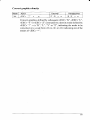
Switches D-3 to D-5: Code Page or International Character Set
Except in the Standard Italic character set, these switches select the
default character code page as shown below:
Code Page
#437 U.S.A.
#850 Multi-lingual
#860 Portuguese
#861 Icelandic
#863 Canadian French
#865 Nordic
D-3
ON
OFF
ON
OFF
ON
OFF
D-4
ON
ON
OFF
OFF
ON
ON
D-5
ON
ON
ON
ON
OFF
OFF
International character sets differ in their assignment of 12 character
codes in the Standard Italic character set. See the character tables in
Chapter 11. With these switches you can select one of eight character
sets as follows:
Country
U.S.A.
France
Germany
England
Denmark I
Sweden
Italy
Spain I
D-3
ON
OFF
ON
OFF
ON
OFF
m“
OFF
D-4
ON
ON
OFF
OFF
ON
ON
OFF
OFF
D-5
ON
ON
ON
ON
OFF
OFF
OFF
OFF
Switches E-1 to E-3: LQ Font Selection
These switches allow you to choose the default font selected when LQ
mode is selected, as shown below.
Font Name
Roman
Sanserif
Courier
Prestige
Script
46
E-1
ON
OFF
ON
OFF
ON
E-2
ON
ON
OFF
OFF
ON
E-3
ON
ON
ON
ON
OFF
chapter 6
TROUBLESHOOTING
This chapter helps you identify printer conditions and problems that you can
often correct yourself.
Your printer is a reliable piece of precision machinery, which should not
cause you any trouble, provided it is used and treated sensibly. However, the
few elementary tips below shouldhelp you avoid having to make unnecessary
service calls.
Remember that your printer is a highly sophisticated electronic device,
which also contains high voltage. For that reason, only carry out those
operations described in this chapter.
CAUTION: Any attempt to carry out operations other than those described
here may result in electric shock and/or damage to the printer.
When carrying out any repairs or maintenance, always follow
the instructions carefully.
●
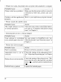
Power switch is on, but power indicator is off
I Action
Probable Cause
Printer is not receivingpower. Make sure that the power cord is correctly
connected.
Verify that the power source works.
●
Printer sounds as if it is printing but does not; Printing is weak
Action
Make sure that the ribbon cartridge is correctly installed.
Make sure that the ribbon is between the
shield on the print head and the end of the
print head. Replace the ribbon.
Adjustment lever is set incor- Check the setting of the adjustment lever.
re.ctly.
Move the lever to a darker setting.
Probable Cause
Ribbon is jamming, twisted,
Ior not between theprint head\
and the print head shield.
47
I
●
Printer test works, but printer does not print when attached to computer
I
I Action
IProbable Cause
Printer cable has a problem. Make sure that the printer cable is correctly
connected at both ends, printer and computer.
Problem with the application Refer to your application program manual.
program.
●
Printer sounds the audible alarm
I Action
\Probable Cause
This might indicate an error Check the status of the control panel indicators and see “Conditions indicated by beep
or normal operation.
tones” in Chapter 4.
●
Selected pitch or font is being changed
]Probable Cause
I Action
Set your printer in Font/Pitch lock. See
“Pitch lock mode” and “Font lock mode” in
Chapter 4.
●
Printer does not feed paper
Probable Cause
Paper is jamming.
Action
Remove all forms and pieces of paper.
Adjustment lever is set in- Check the setting of the adjustment lever.
See “Adjusting the printing gap” in Chapter
correctly.
3.
Releaseleveris setincorrectly. Check the setting of the release lever. This
lever must be set to the back for cut-sheet
forms (.~ ), and forward for fanfold forms
( ~).
\Fanfold form isparked.
48
Unpack the fanfold paper.
Line spacing is incorrect or overprinting occurs
●
Action
The tractor positions are in- Adjust the tractor positions. See “Loading
fanfold forms” in Chapter 3.
correctly adjusted.
Probable Cause
Problem with the application Refer to your application program manual.
program.
Platen knob was manually Set the top of form. See “Top of form” in
turned while the POWER in- Chapter 4.
Do not manually turn the platen knob when
dicator was on.
the power is on. Use the (PAPER FEED;
button.
Forms are jamming between Reset adjustment lever. See “Adjusting the
printing surface and the print printing gap” in Chapter 3.
head.
Incorrect number of lines on a page
●
Action
Probable Cause
Paper is adjusted incorrectly. Set the top of form. See “Top of form” in
Chapter 4.
Paper has shifted backwards Readjust forms.
after several forms printed
correctly.
Problem with the application Refer to your application program manual.
program.
Distance printer must pull Move paper closer to the printer.
paper is too far.
Paper is getting stuck on ca- Move the paper away from any wires or
bles.
cables.
●
Line Iength is wrong: Graphics do not print; Lines are not starting at left
margin
Action
Probable Cause
Problem with the application Refer to your application program manual.
program.
49
●
Characters are wrong or missing; formatting control codes do not work
Action
Probable Cause
Problem with the application Refer to your application program manual.
program.
Some wires are missing from Printer needs repair.
the print head.
Wrong default setting with Check the current EDS setting. Modify the
EDS switches.
EDS setting.
●
Dots are missing or print quality is poor
Action
Probable Cause
Adjustment lever is set incor- Check the position of the adjustment lever.
See Chapter 3.
rectly.
Print head is not working.
●
Printer needs repair.
Forms are smudged or printing is too dark
Probable Cause
Action
Adjustment lever is set incor- Check the position of the adjustment lever.
Move the lever to a lighter setting (front).
rectly.
See Chapter 3.
Ribbon is twisted or is not Install the ribbon correctly. See “Installing
between the print head and the ribbon cartridge” in Chapter 2.
the print head shield.
Print head shield (or print See “Installing the ribbon cartridge” in
head) is damaged or missing. Chapter 2 to locate the print head shield and
print head. Contact your dealer.
●
Printer is unstable; Wrong characters are printed; Left margin changes;
Printing stops
Probable Cause
Static electricity is resulting
from low humidity or interference from nearby electrical devices.
50
Action
Increase the humidity.
Move devices with electric motors away
from the printer.
Left margin moves to the right during printing
●
Action
Probable Cause
The print head is not moving Check that the ribbon and paper are correctly installed. See “Installing ribbon carcorrectly.
tridge” in Chapter2 and “Loading paper” in
Chapter 3.
Problem with the application Refer to your application program manual.
program.
r
The adjustment lever is in the Reset the adjustment lever. See “Adjusting
the printing gap” in Chapter 3.
wrong position.
Printer is printing beyond side edge of forms
●
Action
Probable Cause
Paper is adjusted incorrectly. Adjust both paper guides and the paper.
Problem with the application Refer to your application program manual.
program.
A print head jam caused by Make sure that the ribbon cartridge is correctly installed. See “Installing the ribbon
the ribbon or a paper jam.
cartridge” in Chapter 2.
Clear the paper jam.
Printer case is hot to the touch
●
Probable Cause
Printer’s vents are blocked.
●
Action
Move object away from the air vents, including the bottom of the printer.
Printer is noisy
Probable Cause
The printer vibrates.
Action
Move any objects that touch the printer.
Ensure that the printer is on a level, sturdy
surface.
Printer covers are open.
Close covers.
1
MAINTENANCE
Essentially, your printer is a robust piece of equipment, but should be treated
with a modicum of care in order to avoid malfunctions. For example:
●
●
●
●
●
52
Keep your printer in a “comfortable” environment. Roughly speaking, if
you are comfortable, then the environment is suitable for your printer (see
Chapter 2).
Do not subject the printer to physical shocks or excessive vibration.
Avoid over-dusty environments. Dust is the enemy of all precision
mechanical devices.
To clean theexteriorofthe printer, use aclothbarely dampened with either
water containing a little detergent or a little alcohol, but do not allow any
liquid to fall inside the printer.
The interior of the printer maybe cleaned with a small vacuum cleaner or
a compressed-air aerosol (sold for this purpose). When performing this
operation, be sure not to bend or damage any cable connections or
electronic components.
chapter 7
OPTIONAL ACCESSORIES
You can select the following accessories as optional equipment.
Automatic sheet feeder (SF- 15DJ)
Pull tractor unit (PT- 15XJ)
Serial interface cartridge (IS-8XL)
This chapter describes how to install and use these optional accessories.
●
●
●
NOTE: Before you install or remove the optional accessories, turn off the
power switch.
AUTOMATIC SHEET FEEDER (SF-15DJ)
You can use the Automatic Sheet Feeder (ASF) to print on cut forms.
Before installing the ASF, check each item in the box against Figure 7-1 to
make sure that you have everything.
Figure 7-1. Check to make sure you have all five items: 1) Sheet Feeder, 2) Hopper attachment, 3) Stacker
attachment, and 4) Printer cover, and 5) ASF User’s manual.
NOTE: The Automatic Sheet Feeder is protected by packing and tape during
shipping. Be sure to remove all of the protective material and tape
before use.
53
Setting up
The procedure for installing the ASF is:
1. Usethe printer’s EDS mode to specify ASF as “installed”. (For details,
refer to Chapter 5.)
2. Open the front cover by lifting up the front using the two grips on either
side, then remove the cover by pulling up.
3. Remove the paper guide, and move the release lever at the back of the
printer to the rear position as shown in Figure 7-2.
4. Move the bail lever on top of the printer to open the paper bail.
Figure 7-2. Remove the front cover from the printer.
5. Secure the mounting brackets of..the Automatic Sheet Feeder onto the
shaft of the platen by lowering it into position as shown in Figure 7-3.
I
Figure 7-3. Mount the Automatic Sheet Feeder onto the printer
54
6. Confirm thatthemounting brackets on both sides of the Automatic Sheet
Feeder are correctly engaged on the printer. When they are engaged
correctly, the ejection roller can be rotated by turning the platen knob.
7. Install tie printer cover provided with the Automatic Sheet Feeder.
Figure 7-4. Install the printer cover.
8.
Insert the hopper attachment on top of the hopper support section as
shown in Figure 7-5.
I
Figure 7-5. Inserl the hopper attachment.
I
9. Insert the stacker attachment, squeezing it with your hand, into the fixing
groove in the front part of the sheet feeder as shown in Figure 7-6.
Figure 7-6. Insert the stacker attachment.
Now you can use the ASF by installing the paper stack into the hopper.
NOTE: Set the front cover and paper guide aside carefully after they have
been removed from the printer. Reverse the procedure described
above when removing the Automatic Sheet Feeder.
56
Loading paper
1. If fanfold paper has already been loaded into the printer, park the paper
through the rear slot.
7-. Push the printer release lever toward the rear of the printer ( ~ ) to load
single sheets.
Pull
the paper loading lever toward the front of the printer to draw the
3.
hopper out until it is in position.
4. Adjust the left paper guide to the desired left position by moving it
horizontally in either direction.
Figure 7-7. Adjust the paper guides to
accornrnmlate
thewidthof the PaPer
5: Fan the paper stack and square it off properly before inserting it into the
Automatic Sheet Feeder.
Figure 7-8. Fan the paper before inserting it into the ASF.
57
6. Insert the paper stack into the Automatic Sheet Feeder.
The stack should not be more than 50 sheets of 20 lb paper.
If necessary, remove some sheets. The ASF may not perform satisfactorily if it is overloaded.
7. Adjust the right paper guide to accommodate the width of the paper.
The guides should be adjusted to restrict the amount of horizontal play
while allowing the paper to slide up and down freely between the two
paper guides. The ideal distance between paper ream and paper guides is
0.25 mm (0.0 1“)on both sides at the narrowest part of the paper guides.
8. Push the paper loading lever toward the rear of the printer.
1
I
Figure 7-9. Push the paper loading lever to hold the paper stack.
Now you are ready to start printing with the Automatic Sheet Feeder.
58
PULL TRACTOR UNIT (PT-15XJ)
When printing on multi-part fanfold paper such as slips,use the PT- 15XJPull
tractor unit. Since printing is carried out while the paper is pulled, printouts
on the original and duplicate paper are always aligned well.
Before installing the Pull tractor unit, check each item in the box against
Figure 7-10 to make sure that you have everything.
Figure 7-10 Check to make sure you have all three items: 1) Pull tractor, 2) Paper su~port, and 3) Printer
cover
59
Setting
The procedure for installing the Pull tractor unit is:
1. Attach the paper support to the pull tractor.
Figure 7-11. Attach the paper support to the pull tractor
2. Remove the front cover and the paper guide from the printer.
3. Set the release leverto the front of the printer(~), then pull the bail lever
towards you to release the bail roller from the platen.
4. Pressing the right and left lock levers, align the fitting area of the pull
tractor with that of the printer body, and push the pull tractor from the top
gradually until it is set in place correctly.
Figure 7-12. Place the pull tractor unit onto the printer.
5. Install the printer cover provided with the pull tractor unit.
60
Loading paper
1. Place a stack of fanfold paper behind and at least one page-length below
the printer.
2. Turn the printer’s power OFF, and remove the printer cover.
3. Hold the fanfold paper by hand so that the rear side of the paper is facing
upwards, then set the end of the paper into the entry slot for cut-sheet
forms and load the paper into the printer.
Figure 7-13. Inseri the paper from the entry slot for cut-sheet forms
4. Pull the paper about one page towards the sprocket guides.
5. Adjust the spacing of thetractorunits by sliding them along the bar, using
the clamp lever at the side of each unit to release them and lock them in
position. The unit is released when the clamp lever is down and locked
when the clamp lever is up.
Clamp lever
Figure 7-14. Adjust the sprocket guides.
61
6. With the tractor covers open, mount the paper by aligning holes with the
pins on the tractor unit.
Figure 7-75. Mount the fanfold paper over the tractor units
..
.
.
..
.,
.,
,!
7. Now close the tractor covers, again maKlngsure tnat me paper noles are
aligned with the pins on the tractor units. If they are not aligned properly,
you will have problems with paper feeding, possibly resulting in tearing
and jamming of the paper.
8. Remount the printer cover.
9. Turn the platen knob to set the print starting position of the paper.
62
SERIAL INTERFACE CARTRIDGE
To run the printer in serial mode, you should use the optional Serial Interface
Cartridge, IS-8XL.
The procedure for installing the interface cartridge is:
1. Set the DIP switches on the IS-8XL before attaching it to the printer. (See
next page for detailed information.)
2. Turn off the power switch and disconnect the power cord from the power
source.
3. Disconnect the interface cable if attached.
4. Slide out the parallel interface cartridge by gripping the flips on both
sides.
5. Insert the Serial interface cartridge all the way, as shown in Figure 7-16.
.,
I
Figure 7-17. Replace the interface cartridge.
6. Connect the Serial interface cable both to the printer and to your
computer.
63
DIP switch functions on the Serial
cartridge
It is necessary to make compatible the data transfer conditions between the
computer and the serial interface cartridge with the DIP switch settings on
the cartridge.
The followingtable shows the functions of the DIP switches on the Serial
Interface Cartridge.
Switch
1
2
3
4
5
6
7
Function
Data length
Parity condition
ON
8-bit
(Refer below)
Data Protocol
(Refer below)
Parity condition
(Refer below)
Transfer speed
(Refer below)
8
[Parity condition]
\ Switch 2
ON
ON
OFF
] OFF
Switch 5
ON
OFF
ON
I OFF
Condition
No parity
Odd ~aritv
I Even~aritv
I
[Data protocol]
Switch3
ON
ON
OFF
Switch 4
ON
OFF
ON
Protocol
DTR
XON/XOFF
ETX/ACK
[Transfer speed]
Switch 6
OFF
OFF
OFF
OFF
ON
ON
ON
] ON
64
I Switch 7
Switch 8
Transfer speed
] OFF
I OFF
150 BPS
300 BPS
OFF
ON
ON
OFF
600 BPS
I ON
j ON
1200 BPS
I OFF
I OFF
I1 2400 BPS
OFF
ON
I 4800 BPS
ON
OFF
I 9600 BPS
I ON
ON
19200BPS
OFF
7-bit
chapter8
PRINTER CONTROL COMMANDS
This printer has two emulation modes: Standard/Epson mode and IBM
mode,
In Standard/Epson mode, the printer emulates the functions of the Epson LQ1060 and the graphics commands for NEC 24-wire printers. In IBM mode,
the printer emulates the IBM Proprinter XL24E. Additional command codes
are included as a superset of these emulations.
The emulation is changed by means of EDS switch A-1. When it is ON, the
printer is in Standard/Epson mode, and when OFF, the printer is in IBM mode
(see Chapter 5).
In addition, when EDS switch A-2 is ON, the printer automatically changes
the emulation by means of software control.
This chapter describes the printer’s control commands. Some commands are
common to both the Standard and IBM modes. In the descriptions of the
commands, all commands will be given by functions. The name of each
command is followed by a table like the one below:
Mode
Std.
ASCII
<ESC>
“X”
<1>
Decimal
27 120 1
Hexadecimal
IB 78 01
Mode:
Indicates the mode in which the command is recognized.
Std. Standard/Epson mode
(EDS switch A-1 is ON)
IBM IBM mode (EDS switch A-1 is OFF)
Both Both Standard/Epson and IBM modes
ASCII:
Indicates the ASCII coding of the command. Control
characters are enclosed in pointed brackets: For example, <1> means character code 1.
Decimal:
Gives the command in decimal character codes.
Hexadecimal: Gives the command in hexadecimal character codes.
Parameters for which values must be supplied are indicated by italic letters
such as n, m or d.
65
I
FONT CONTROL COMMANDS
Select print quality
Mode
Std.
ASCII
<ESC>
Hexadecimal
Decimal
“’X”
27 120
n
1B 78
n
n
Changes the print quality according to the value of n, as shown
below:
n
Print quality
o
1
Draft
Letter quality
Ignored if the FONT LOCK mode was selected during power-up.
Select print quality
Mode
IBM
ASCII
<ESC>
“[” ‘cd” <1> <0> n
Decimal
27 91 100 1 0
Hexadecimal
n
IB 5B 64 01 00 n
Changes the print quality according to the value of n, as shown
below:
n
Print quality
o
Unchanged
Draft
,.
Letter quality
Return to EDS setting
1.-127
128-254
255
Ignored if the FONT LOCK mode was selected during power-up.
Select LQfont
Mode
Both
ASCII
<ESC> “k”
n
Decimal
27 107 n
Hexadecimal
IB” 66
n
Selects an LQ font according to the value of n. In draft mode, this
command remains dormant and takes effect later when LQ is
selected. Ignored if the FONT LOCK mode was selected during
power-up.
66
n
Font
o
1
2
3
4
Roman
Sanserif
Courier
Prestige
Script
Select italic characters
Mode
Std.
ASCII
<ESC>
Decimal
“4”
27 52
Hexadecimal
IB 34
Causes subsequent characters except IBM block graphics to be
printed in italics.
Select upright characters
Mode
Std.
ASCII
<ESC> “5”
Decimal
27 53
Hexadecimal
IB 35
Stops italic printing and causes subsequent characters to be printed
upright.
Emphasized printing
Mode
Both
ASCII
<ESC> “E”
Decimal
27 69
Hexadecimal
IB 45
Causes subsequent characters to be emphasized by adding extra
thickness to horizontal strokes.
Cancel emphasized printing
Mode
Both
ASCII
<ESC> “F”
Cancels emphasized printing.
Decimal
27 70
Hexadecimal
IB 46
Double-strike printing
Mode
Both
Decimal
ASCII
<ESC>
27
“G”
71
Hexadecimal
IB 47
Causes subsequent characters to be printed in double-strike mode
with a slight vertical paper motion in between, causing a thickening
of vertical strokes.
For bold print, use of double-strike is recommended in LQ mode,
and combined use of emphasized and double-strike is recommended
in draft mode.
Cancel double-strike printing
Mode] ASCII
Both ] <ESC> “’H”
Decimal
27 72
IB 48
Hexadecimal
Decimal
27 45 n
IB 2D
Cancels double-strike printing.
Underlining
Model ASCII
<ESC> “’–”’ )1
Both
Hexadecimal
n
Causes subsequent characters to be underlined when n is 1,and stops
underlining when n is O. Block graphics characters and spaces
skipped by horizontal tabulation are not underlined.
Overlinittg
Model ASCII
<ESC> “-”
IBM
n
Decimal
27 95 n
Hexadecimal
IB 5F
n
Causes subsequent characters to be overlined when n is 1,and stops
overlining when n is O.Spaces skipped by horizontal tabulation are
not overlined.
68
Select score
Mode
Std.
ASCII
<ESC> “’(” “-”
<o>
<1>
Decimal
27 40 45
<3>
n1
o
n2
1
nl
Hexadecimal
3
n2
IB 28 2D 03
00 01 n/ n2
Start score according to the values of nl and n2, as shown below.
nl
Function
n2
Function
1
2
3
Underlining
Strike-through
Overlining
O
1
2
5
6
Cancel score
Single continuous line
Double continuous line
Single broken line
Double broken line
Select ornament character
Model ASCII
<ESC> “q”
Std.
Decimal
27 113
n
n
Hexadecimal
IB 71
n
Selects an ornament character according to the value of n, as shown
below.
n Character
O
1
2
3
Normal
Outline
Shadow
Shadow and outline
Superscript
Mode
Both
ASCII
<ESC> “s”
Decimal
<0>
27 83
0
Hexadecimal
IB 53 00
Causes subsequent characters to be printed as superscripts. Does not
change the character pitch.
69
Subscript
Mode
Both
ASCII
<ESC>
Decimal
“s’”
<1>
27 83
1
Hexadecimal
IB 53 01
Causes subsequent characters to be printed as subscripts. Does not
change the character pitch.
Cancel superscript or subscript
Mode
Both
ASCII
<ESC> “T”
Decimal
27 84
Hexadecimal
IB 54
Stops printing superscripts or subscripts and returns to normal
printing.
..
70
CHARACTER SET COMMANDS
Select character table
Model ASCII
Both I <ESC>
Std. I <FS>
I
“t”
“1”
/1
H
Decimal
I
Hexadecimal
I 27116
n
/ IB 74
n
I 28 73
n
] Ic
n
49
Selects a character table according to the value of n as shown below:
n
Character table
o
Standard character set
IBM character set
Shift download character area
1
2
Select character set #l
Mode
Both
ASCII
<ESC> ?
Decimal
27 55
Hexadecimal
IB 37
Selects character set #1.
Select character set #2
Mode
Both
ASCII
<ESC> “6”
Decimal
27 54
Hexadecimal
IB 36
Selects character set #2.
71
I
Select international character set
I Model ASCII
I Std. I <ESC> “R”
I Decimal
/ 27 82 n
n
I
Hexadecimal
I IB 52
n
/
I
Selects an international character set in the Standard character set
according to the value of n.
n
Character set
n
Character set
O
1
2
3
4
5
6
7
U.S.A
France
Germany
England
Denmark I
Sweden
Italy
Spain I
8
9
10
11
12
13
14
64
Japan
Norway
Denmark II
Spain II
Latin America
Korea
Ireland
Legal
The first eight of these character sets (from U.S.A. to Spain I) can be
selected as the power-up default by EDS switches D-3 to D-5.
Select IBM code page
Mode
Both
Decimal
ASCII
<ESC> “[”
<0>
<4>
“T”
<o>
III
<0>
n2
Hexadecimal
27 91 84
o
0
17/
4
0
n2
IB 5B 54 04 00
00
00
nl
n2
Changes the code page of the current IBM character set according
tOthe values of nl and n2, as shown below.
n]
n2
Code ua~e
1
3
3
3
3
3
181
82
92
93
95
97
#437 U.S.A.
#850 Multi-Lingual
#860 Portuguese
#861 Icelandic
#863 Canadian French
#865 Nordic
One of these code pages can be selected as the power-up default by
EDS switches D-3 to D-5.
72
Enable printing of all character codes
I
I
Decimal
Model
Std.
ASCII
<FS>
“\”
Ill
n2
23
I13M
<ESC>
‘Y”
Ill
112
27 92 n] )12
92 III
112
Hexadecimal
Ic
I
5C 1?/ rd
IB 5C n/
n2
Enables printing of all characters in the IBM character set, including those
assigned to character codes which are normally considered control codes.
This command remains in effect for the next nl + rz2x 256 characters, where
nl and rz2are numbers between Oand 255. During this interval no control
functions are executed. If a code with no assigned character is received, the
printer prints a space,
Enable printing of all character codes on next character
Mode ASCII
<FS> ,’ ~ ,. n
Std.
IBM - <ESC> ‘cA“ n
Decimal
28 94 n
27 94 n
Hexadecimal
IC 5E
n
IB 5E
n
This command operates like <ESC> ‘1” except that it remains in effect for
only one character.
I
CHARACTER SIZE AND PITCH COMMANDS
Pica pitch
I
/Mode] ASCII
Std.
<ESC> “P”
IBM . <DC2>
Decimal
\
Hexadecimal
27 80
IB 50
18
12
]
In Standard mode, changes from either elite or semi-condensed to
pica pitch (10 cpi) or from condensed elite to condensed pica ( 17
cpi). In IBM mode, changes from elite or condensed to pica (10cpi).
Ignored if the PITCH LOCK mode was selected during power-on.
Elite pitch
Mode
Std.
ASCII
<ESC> “M”
27 77
Decimal
IB 4D
IBM
<ESC>
27 58
IB 3A
“:”
Hexadecimal
In Standard mode, changes from either pica or semi-condensed to
elite pitch (12 cpi) or from condensed pica to condensed elite (20
cpi). In IBM mode, changes from pica or condensed to elite ( 12cpi).
Ignored if the PITCH LOCK mode was selected during power-on.
Semi-condensed pitch
Mode
Std.
Decimal
ASCII
<ESC> “g”
27 103
Hexadecimal
IB 67
Changes from either pica or elite to semi-condensed pitch (15 cpi).
Ignored if the PITCH LOCK mode was selected during power-up.
Condensed printing
Mode
Both
ASCII
Decimal
<s1>
<ESC>
<S1>
Hexadecimal
15
OF
27 15
IB OF
In Standard mode, changes from pica to condensed pica ( 17 cpi) or
from elite to condensed elite (20 cpi). In IBM mode, changes from
pica to condensed pica.
Ignored if the PITCH LOCK mode was selected during power-on.
74
Cancel condensed printing
Mode
Both
ASCII
<DC2>
Hexadecimal
Decimal
18
12
In Standard mode, changes from condensed pica to normal pica or
from condensed elite to normal elite. In IBM mode, always changes
to normal pica.
Ignored if the PITCH LOCK mode was selected during power-on.
Proportional spacing
Mode
Std.
IBM
ASCII
<ESC> “p”
<ESC> “P”
Hexadecimal
Decimal
)7
27 112 n
IB
70
n
n
27
IB
50
n
80 n
Causes subsequent characters to be proportionally spaced when n is
1,and cancels it when n is O.Ignored if the PITCH LOCK mode was
selected during power-up.
Select font and pitch
Mode
IBM
ASCII
<ESC> “I”
Hexadecimal
Decimal
n
27
73
n
IB
49
n
Changes the print font and pitch according to the value of n, as shown
,below:
Pitch
Font
n
o
2
3
4
6
7
8
10
12
14
16
18
20
22
Draft
Letter Quality
Letter Quality
Draft download
LQ download
LQ download
Draft
Letter Quality
Draft download
LQ download
Draft
Letter Quality
Draft download
LQ download
Pica
Pica
Proportional
Pica
Pica
Proportional
Elite
Elite
Elite
Elite
Pica condensed
Pica condensed
Pica condensed
Pica condensed
75
Select print mode
Mode
IBM
Decimal
ASCII
<ESC>
“[”
<o>
<2>
“1”
nl
Hexadecimal
27 91 73
n]
n2
2
0
IB 5B 49 02 00
n2
n]
d
Changes the print mode according to the values of nl and n2, as
shown below.
id
~2
o
0
11
12
18
46
57
60
85
86
92
108
111
112
116
164
171
172
184
185
221
253
254
0
0
0
0
0
0
0
0
0
0
0
0
0
0
0
0
0
0
0
11
1
1
1
1
1
1
1
1
76
201
202
235
236
237
238
239
240
Font
Mode
Pitch
Courier
Prestige
Courier
Courier
Courier
Prestige
Courier
Prestige
Courier
Courier
Prestige
Prestige
Courier
Prestige
Courier
Courier
Courier
Courier
Prestige
Courier
Courier
Prestige
Prestige
Prestige
Courier
Courier
Courier
Courier
Prestige
Prestige
Normal
Normal
Italic
Emphasized
Italic emphasized
Emphasized
Normal
Normal
Italic
Emphasized
Emphasized
Italic
Italic emphasized
Normal
Normal
Italic
Emphasized
Italic emphasized
Normal
Emphasized
Normal
Normal
Normal
Normal
Normal
Normal
Normal
Normal
Normal
Normal
Pica
Pica
Pica
Pica
Pica
Pica
Elite
Elite
Elite
Elite
Elite
Elite
Elite
Proportional
Proportional
Proportional
Proportional
Proportional
Semi-condensed
Pica condensed
Pica condensed
Pica condensed
Pica condensed
Elite condensed
Elite
Semi-condensed
Pica condensed
Elite condensed
Elite
Semi-condensed
Expanded printing
Mode
Both
ASCII
<ESC> “W”
Decimal
27 87
n
n
Hexadecimal
IB 57
n
Causes subsequent characters to be expanded to double width when
n is 1, and cancels it when n is O.
Expanded printing for one line
Mode
Both
Decimal
ASCII
<so>
<ESC>
<so>
Hexadecimal
14
OE
27 14
IB OE
Causes subsequent characters in the current line to be expanded to
double width. Characters return to normal width after the next line
feed (ELF>). The <DC4>, <VT>, <FF>, and <ESC> “W” Ocommands also cancel expanded printing.
Cancel one-line expanded printing
Mode
Both
Decimal
ASCII
<DC4>
20
Hexadecimal
14
Stops one-line expanded printing set with <S0> or <ESC> <S0>.
Does not cancel <ESC> “W” 1.
Select character width
Mode
Std.
ASCII
<FS>
Decimal
“E”
28 69
n
n
Hexadecimal
IC 45
n
Selects a character width according to the value of n as shown below.
n
Character width
O Normal-wide
1 Double-wide
2 Triple-wide
Select master print mode
IMode/ ASCII
I Std. I <ESC>
I Decimal
I 27 33 n
,’,>3
.
n
I
Hexadecimal
I IB 21
n
I
I
Selects a combined print mode according to the value of n. The value
ofn isthe sumof thevaluesgivenbelow forthedesiredcharacteristics.
Function
n value
128
64
32
16
8
4
2
1
Underline
Italic
Expanded
Double strike
Emphasized
Condensed
Proportional
Elite
Increase character spacing
Mode
Std.
Decimal
ASCII
<ESC>
<SP>
n
27 32
n
Hexadecimal
IB 20
n
Increases the space between characters by n dots, where n is a
number from Oto 127. Used in microjustification.
The unit of movement is fixed at 1/120inch in draft mode and 1/180
inch in LQ mode.
Print double-height characters
Mode
Std.
ASCII
<ESC>
“W”
<1>
27 119
Decimal
1
IB 77 01
Hexadecimal
<FS>
“v”
<1>
28 86
1
IC
56 01
Prints subsequent characters at double height without moving the
base line and without changing the line spacing.
78
Return to normal height
Mode
Std.
ASCII
<ESC>
<FS>
Decimal
Hexadecimal
‘“W”
<()>
27 119
0
IB 77 00
“v”
<t)>
28 86
0
IC
56 00
Terminates double-height printing and prints subsequent characters
at normal height.
Select character height, width, and line spacing
Mode
IBM
Decimal
ASCII
<ESC> “[” “(ZJ” <4> <o>
n
n7
<o> <o>
Hexadecimal
27 91 64
o
0
4
n
0
m
IB 5B 40 04 00
00 00 n m
Selects a combination of character height, width, and line spacing
according to the value of n and m, as shown below. Does not move
the base line,
n
Line spacing
Character height
o
Unchanged
Unchanged
Unchanged
Single line
Single line
Single line
Double line
Double line
Double line
Unchanged
Single height
Double height
Unchanged
Single height
Double height
Unchanged
Single height
Double height
1
2
16
17
18
32
33
34
m
Character width
o
Unchanged
Single width (same as <ESC> “W” O)
Double width (same as <ESC> “W” 1)
1
2
79
I
VERTICAL
COMMANDS
Set line spacing to 1/8 inch
Mode
Both
ASCII
<ESC> W“
Decimal
27 48
Hexadecimal
IB 30
Sets the distance the paper advances or reverses in subsequent line
feeds to 1/8 inch.
Set line spacing to 1/6 inch
Mode
Std.
ASCII
<ESC> “2”
Hexadecimal
Decimal
27 50
IB 32
Sets the distance the paper advances or reverses in subsequent line
feeds to 1/6 inch.
Set line spacing to n1360inch
Mode
Std.
ASCII
<ESC> ‘6+”
<FS>
Decimal
“3”
Hexadecimal
n
27 43
n
1B 2B
n
n
28 51
n
IC 33
n
Sets the distance the paper advances or reverses in subsequent line
feeds to n/360 inch, where n is between Oand 255.
Set base unitfor line spacing
Mode
IBM
ASCII
<ESC>
<0>
Hexadecimal
Decimal
“ [“
“1”
<0>
<4>
nl
<0>
n2
27 91 92
o
0 nl
4
0
n2
IB 5B 5C 04 00
00
00
nl
n2
Sets the base unit for the line spacing commands, <ESC> “3” and
<ESC> “J”, as shown below:
80
n1
n2
Line spacing unit
o
o
1
180
216
104
1/180 inch
1/216 inch
1/360 inch
If otherwise specified, this command is ignored. This command
becomes effective only after <ESC> “3” or <ESC> “J” is received.
The default base unit is set to 1/216”.
Set line spacing
Mode
Both
ASCII
<ESC> “3”
Decimal
/?
27 51
)1
Hexadecimal
IB 33
n
Sets the distance the paper advances or reverses in subsequent line
feeds to n/180 inch, n/216 inch or n/360 inch (n/180 inch for the
Standard mode) according to the preceding base unit.
The value of n is between Oand 255. If n = O,in Standard mode the
line-feed distance is set to O, but in IBM mode this command is
ignored.
Set line spacing to n160inch or n172inch
Mode
Both
ASCII
<ESC> “A”
Decimal
n
27 65
n
Hexadecimal
1B 41
n
In Standard mode, sets the distance the paper advances or reverses
in subsequent line feeds to n/60 inch, where n is between Oand 255.
If n = O,the line spacing is set to O.
In IBM mode, this command defines the distance the paper advances
or reverses in subsequent line feeds to n/72 inch, where n is between
1 and 85. The new line’spacing does not take effect until the next
<ESC> “2” command.
Execute dlSC> “A”
Mode
IBM
Decimal
ASCII
<ESC>
“2”
27 50
Hexadecimal
tB 32
Sets the line spacing to the value defined by the last preceding
<ESC> “A” command. Sets the line spacing to 1/6inch if there is no
preceding <ESC> “A” command.
81
Line feed
Mode
Both
ASCII
<LF>
Decimal
10
Hexadecimal
OA
Prints the current line and feeds the paper to the next line. See the
preceding commands for the line spacing.
Reverse line feed
Mode ASCII
Std. I <ESC>
IBM I <ESC>
Decimal
<LF>
“]”
Hexadecimal
I 27 10
I IB OA
27 93
IB 5D
I
Prints the current line and feeds the paper in the reverse direction to
the preceding line. Ignored when the Pull tractor unit is used.
See the preceding commands for the line spacing.
Select forwardfeed mode
Mode
Std.
ASCII
<FS>
Decimal
28 70
“F”
Hexadecimal
IC 46
Cancels the reverse feed mode and selects forward feed mode. This
is the default setting at power-on.
Select reverse feed mode
Mode
Std.
Ascll
<FS>
Decimal
28 82
“R”
Hexadecimal
IC 52
Selects reverse feed mode. Reverses the direction of all vertical
movements. Ignored when the Automatic Sheet Feeder is used.
Perform one time line feed
Mode
Both
ASCII
<ESC> “J”
n
Decimal
27 74 n
Hexadecimal
IB 4A
n
Feeds the paper once by n times the defined base unit (n/l 80 inches
for the Standard mode). The value of n is between Oand 255. If n =
O,the line-feed distance is set to O.Does not move the print position
right or left. Does not change the line-spacing setting.
82
Perform one n/180-inch reverse line feed
Mode
Std.
ASCII
<ESC> “j”
Decimal
n
27 106
Hexadecimal
IB 6A
n
n
Feeds the paperoncebyrz/180 inches in the reverse direction, where
n is between Oand 255. If n = O,the line-feed distance is setto O.Does
not move the print position right or left. Does not change the linespacing setting.
Set page length to n lines
Mode
Both
ASCII
<ESC> “C”
Decimal
n
27 67
Hexadecimal
IB 43
n
n
Sets the page length to Mlines in the current line spacing, where n is
between 1 and 127.
Changing the line spacing later does not alter the physical page
length. The current line becomes the top of the page.
Set page length to n inches
Mode
Both
ASCII
<ESC> “C”
Decimal
<0>
n
27 67
0
Hexadecimal
n
IB 43 00
)1
Sets the page length to n inches, where n is between 1 and 32 in
Standard mode or between 1 and 64 in IBM mode. The current line
becomes the top of the page.
Set top of page at current position
Mode
IBM
ASCII
<ESC>
“4”
Decimal
27 52
Hexadecimal
IB 34
Sets the current position as the top-of-page position.
83
Set bottom margin
Mode
Both
ASCII
<ESC> “N”
Decimal
27 78 n
)7
Hexadecimal
1B 4E 17
Sets the bottom margin ton lines, where n is between 1 and 127 in
Standard mode or between 1 and 255 in IBM mode. The bottom
margin is reset when you change the page length.
Cancel bottom margin
Mode
Both
ASCII
<ESC> “0”
Decimal
Hexadecimal
27 79
IB 4F
Cancels the bottom margin.
Form feed
I Model
Both
ASCII
<FF>
I
Decimal
12
]
Hexadecimal
I
Oc
Feeds the paper to the top of the next page according to the current
page length, and moves the print position to the left margin. When
friction feed is used, this command ejects the current page.
Set vertical tab stops
Mode] ASCII
I Both I <ESC> “B” ,,/
rz2 .... <0>
Decimal
I 2766 nl rz2 .0
Hexadecimal
I IB 42 nl t72 .00
I
Cancels all current vertical tab stops and sets new vertical tab stops
at lines nl, n2, etc., where nl, n2, etc. are numbers between 1 and
255. The maximum number of vertical tab stops allowed is 16 in
Standard mode and 64 in IBM mode. The tab stops must be specified
in ascending order; any violation of ascending order terminates the
tab stop list. Standard termination is by the <0> control code. The
vertical tab stops are set in terms of the current line spacing and do
not move if the line spacing is changed later.
84
Set vertical tab stops in channel
Mode
Sfd.
ASCII
<ESC> “b”
Decimal
27 98 ti)
)11
no
n2
..
<o>
Hexadecimal
n]
n2
1B 62 no
III
/72
0
00
Cancels all current vertical tab stops in channel nO, (where nO is
between 0 and 7) and sets new vertical tab stops in this channel. (A
channel is a set of vertical tab stops selected by the <ESC> “/”
command.) See <ESC> “B” for parameters nl, n2, ... <0>.
Select vertical tab channel
Mode
Std.
Ascll
<ESC> “/”
Decimal
nO
27 47 n(l
Hexadecimal
IB 2F
no
Selects a set of vertical tab stops designated by a channel number
(nO)from Oto 7. The tab stops in each channel are set by <ESC> “b”.
Vertical tab
Mode
Both
ASCII
<VT>
Decimal
11
Hexadecimal
OB
Feeds the paper to the next vertical tab stop and moves the print
position to the left margin. Performs a line feed if no vertical tabs are
set, as at power-up. Feeds to the top of the next page if vertical tabs
are set but the current line is at or below the last vertical tab stop.
I
HORIZONTAL POSITION
Set left margin
Mode
ASCII
I Std. I <ESC>
Decimal
“1”
n
I 27108
n
Hexadecimal
I IB 6C
n
I
Sets the left margin at column n (where n is between Oand 255) in
the current character pitch (pica pitch if proportional spacing is
currently selected). The left margin does not move if the character
pitch is changed later. The left margin must be at least two columns
to the left of the right margin and within the limits below:
Pica
Elite
Semi-condensed
Condensed pica
Condensed elite
Expanded pica
Expanded elite
Expanded semi-condensed
Expanded condensed pica
Expanded condensed elite
Set right margin
Mode
Std.
ASCII
<ESC> “Q”
n
Decimal
27 81 n
Hexadecimal
IB 51
n
Sets the right margin at column n in the current character pitch (pica
pitchifproportionalspacingiscurrentlyselected).Column~zbecomes
the lastcharacter position in the line. The right margin does not move
if the character pitch is changed later. The right margin must be
within the limits below:
Pica
Elite
Semi-condensed
Condensed pica
Condensed elite
Expanded pica
Expanded elite
Expanded semi-condensed
Expanded condensed pica
Expanded condensed elite
86
Set left and right margins
Mode
IBM
ASCII
<ESC> “X”
Decimal
III
n2
27 88 nl
Hexadecimal
n2
IB 58 MI n2
Sets the left margin at column nl and the right margin at column n2.
See the preceding commands for margin restrictions and other notes.
Carriage return
Mode I
I Both I
Decimal
I 13
ASCII
<CR>
Hexadecimal
IOD
I
Prints the current line and returns the next print position to the left
margin. If EDS switch A-5 is set to OFF, also performs a line feed.
Set automatic line feed
Mode
IBM
ASCII
<ESC> “5” <1>
Decimal
27 53 1
Hexadecimal
IB 35 01
Causes the printer to perform both a carriage return and line feed
each time it receives a<CR> code. This command takes priority over
EDS switch A-5.
Cancel automatic line feed
Mode
IBM
ASCII
<ESC>
“5” <0>
Decimal
27 53 0
Hexadecimal
IB 35 00
Causes the printer to perform only a carriage return when it receives
a <CR> code. This command takes priority over EDS switch A-5.
Backspace
Mode
Both
ASCII
<BS>
Decimal
8
Hexadecimal
08
Moves the print position one column to the left. Ignored if the print
position is at the left margin. This command can be used to overstrike
or combine characters.
87
I
Set horizontal tab stops
IModel ASCII
I Both I <ESC> “D” ,,f
172 .
<0>
I Hexadecimal I
I Decimal
I 27 68 rz/ ,,2... 0 I IB 44 rz/ ,,2 ..00 I
Cancels all current horizontal tab stops and sets new tab stops at
columns nl, n2, etc. in the current character pitch (pica pitch if
proportional spacing is currently selected), where nl, n2, etc. are
numbers between 1 and 255. The maximum number of horizontal
tab stops allowed is 32 in Standard mode and 28 in IBM mode. The
tab stops must be specified in ascending order; any violation of
ascending order terminates the tab stop list. Standard termination is
by the <0> control code. To clear all tab stops, specify <ESC> “D”
<o>.
Reset all tab stops
Mode
IBM
ASCII
<ESC> “R”
Decimal
27 82
Hexadecimal
IB 52
Resets the horizontal tab stops to their power-up values according to
which a tab stop is set every 8 colulmnsstarting at column 9. Also
clears all vertical tab stops.
Horizontal tab
Mode
Both
ASCII
<HT>
Decimal
9
Hexadecimal
09
Moves the print position to the next horizontal tab stop. Ignored if
there is no next horizontal tab stop in the current line. Note that when
underlining is selected, spaces skipped by horizontal tabulation are
not underlined.
88
Relative horizontal tab
Mode I ASCII
<ESC> “\”
Std.
Decimal
nl
)12
27
92 n[
Hexadecimal
IB 5C n]
n2
n2
Moves the print position right or left a specified distance. Ignored if
the resulting position is beyond the rightor left margin. The formulas
for the distance and direction are as follows:
If n2 is between Oand 63, the print head moves right by (}?1+ n2 x
256) dots.
If you want to move the print head to the left, nl and n2 are obtained
by subtracting the value from 65536, and dividing the result into
high and low bytes.
The unit of movement is fixed at 1/120inch in draft mode and 1/180
inch in LQ mode.
Relative horizontal tab in inches
/Mode I ASCII
<ESC> “d”
IBM
nl
n2
Decimal
27 100 nl n2
I
Hexadecimal
1B 64 n] n2
Sets the next print position to (nl + n2 x 256)/120 inches from the
current position.
Ignored if this position is beyond the right margin. The maximum
position is 8 inches.
“’”
Absolute horizontal tab in inches
Mode
Std.
ASCII
<ESC> “$”
Decimal
nl
n2
27
36 nl
Hexadecimal
n2
IB 24 nl
n2
Sets the next print position to (rd + n2 x 256)/60 inches from the left
margin on the current line. Ignored if this position is beyond the right
margin.
89
I
GRAPHICS
Print normal-density 8-bit graphics
Mode
Both
Decimal
ASCII
<ESC> “K” /?/ n2
27 75
t?llnz2
n]
Hexadecimal
n2
1B 4B nf n2
ml m2
ml m2
Prints bit-image graphics at 60 dots per inch horizontally. The
graphic image is 8 dots high and nl + n2 x 256 dots wide. Maximum
width is 13.6 inches (8 16 dots). ml, rn2, ... are the dot data, each a
1-bytevalue from Oto 255 representing 8 vertical dots, with the most
significant bit at the top and the least significant bit at the bottom.
The number of data bytes must be nl + n2 x 256. Dots beyond the
right margin are ignored. At the end of bit-image printing the printer
returns automatically to character mode.
Print double-density 8-bit graphics
Mode
Both
ASCII
<ESC> “L”
Decimal
nl
27 76 nl
n2
ml
m2
Hexadecimal
IB 4C nl n2
n2
ml n72
ml m2
Prints bit-image graphics at 120 dots per inch horizontally (maximum 1632 dots wide). See <ESC> “K” for other information.
Print double-density, double-speed 8-bit graphics
Mode
Both
ASCII
<ESC> “Y”
Hexadecimal
Decimal
nl
27 89
d
ml
m2
IB 59 n/ n2
Illn2
ml m2
,.,
ml n12
.
Prints bit-image graphics at 120 dots per inch horizontally (maximum 1632 dots wide), skipping every second dot in the horizontal
direction. See <ESC> “K” for other information.
90
I
Print quadruple-density 8-bit graphics
Mode
Both
ASCII
<ESC> “Z” nl
Decimal
27 90 nl
n2
ml
m2
Hexadecimal
IB 5A n] n2
d
ml m2
ml m2
Prints bit-image graphics at 240 dots per inch horizontally (maximum 3264 dots wide), skipping every second dot in the horizontal
direction. See <ESC> “K” for other information.
Print hex-density 24-bit graphics
Mode
Std.
ASCII
<FS>
Decimal
“Z”
nl
ml
n2
m2
28 90 nl
m3
,,.
Hexadecimal
IC 5A nl n2
n2
ml m2 td
.,.
ml m2 m3 .,,
Prints 24-bit dot graphics at 360 dots per inch horizontally. The
graphics image is 24 dots high and nl + n2 x 256 dots wide. Maximum width is 13.6inches (4896 dots). In the data ml, m2, m3 ... each
three bytes represent 24 vertical dots. In the leftmost position, the
most significant bit of ml is the top dot; the least significant bit of
ml is the eighth dot from the top; the most significant bit of m2 is
the ninth dot; the least significant bit of m2 is the sixteenth dot from
the top; the most significant bit of m3 is the seventeenth dot from the
top; the least significant bit of m3 is the bottom dot. The rest of the
data is similar. The number of data bytes must be 3 x (n] + n2 x 256).
Dots beyond the right margin are ignored. At the end of dot graphics
printing, the printer returns automatically to character mode.
91
Select graphics mode
Mode
Std.
ASCII
<ESC> “*”
Decimal
no
n2
ml
Hexadecimal
27 42 }0 nl
n]
m2
IB 2A no n]
n2 ml m2 .
n2 ml m2
Selects one of eleven graphics modes depending on the value of nO
and prints bit-image graphics in this mode. See <ESC> “K” (for 8bit graphics) or <FS> “Z” (for 24-bit graphics) for information on
nl, n2, ml, m2, ...
HO Graphicsmode
o
1
2
3
4
6
32
33
38
39
40
8-bit Normal-density
8-bit Double-density
8-bit Double-density, double-speed
8-bit Quadruple-density
8-bit CRT graphics, mode I
8-bit CRT graphics, mode II
24-bit Normal-density
24-bit Double-density
24-bit CRT graphics
24-bit Triple-density
24-bit Hex-density
(60 dots per inch)
( 120 dots per inch)
(120 dots per inch)
(240 dots per inch)
( 80 dots per inch)
(90 dots per inch)
(60 dots per inch)
(120 dots per inch)
(90 dots per inch)
(180 dots per inch)
(360 dots per inch)
Select graphics mode
Mode
IBM
ASCII
<ESC> “[”
Decimal
“g”
m(l
nl
ml
Hexadecimal
n2
27 91 103 nln2
m2
mOml m2
IB 5B 67 n/ n2
mOml m2
Selects one of eight graphics modes depending on the value of mO
and prints bit-image graphics in this mode. The graphics image is (n]
+ n2 x 256) – 1 dots wide. See <ESC> “K” (for 8-bit graphics) or
<FS> “Z” (for 24-bit graphics) for information on ml, m2, ...
mO Graphics mode
o
1
2
3
8
9
11
12
92
8-bit Normal-density
8-bit Double-density
8-bit Double-density, double-speed
8-bit Quadruple-density
24-bit Normal-density
24-bit Double-density
24-bit Triple-density
24-bit Hex-density
(60 dots per inch)
( 120 dots per inch)
(120 dots per inch)
(240 dots per inch)
(60 dots per inch)
(120 dots per inch)
( 180 dots per inch)
(360 dots per inch)
Convert graphics density
Mode
Std.
ASCII
<ESC> “?”
Decimal
n
m
27 63
n
Hexadecimal
m
IB 3F
n
m
Converts graphics defined by subsequent <ESC> “K”, <ESC> “L”,
<ESC> “Y” or <ESC> “Z” commands to a density mode defined by
<ESC> “*”. n is “K”, “L“, “Y” or “Z”, indicating the mode to be
converted. m is a code from <0> to <4> or <6> indicating one of the
modes of <ESC> “*”.
93
I
DOWNLOAD CHARACTER
Define download characters
Mode
ASCII
Decimal
<ESC>. “’&”<0> nf
Std.
,t~
d[
mO ml
(u
27 38
m2
d.!
n2
0 nl
mo ml
dl
Hexadecimal
w
IB 26 00 n/
m2
([.1
n2
mo m/
dl d2
m2
d.1
Defines one or more new characters and stores them in RAM for
later use. EDS switch A-3 must be set OFF; otherwise RAM is used
as an input buffer, not downloading characters, and this command is
ignored.
nl is the character code of the first character defined and /12is the
character code of the last character defined. nl must be equal to or
less than n2.
The data for each character start with three bytes specifying proportional spacing attributes: the first byte, mo, specifies the left of the
character; the second byte, ml, specifies the character width; the
third byte, m2, specifies the right of the character.
These values must not exceed the following maximum limits:
Character mode
ml
mO+ ml + n/2
Draft
LQ pica
LQ elite
LQ semi-condensed
LQ proportional
Draft super/subscript
LQ super/subscript
LQ prop. super/subscript
9
31
27
19
38
7
19
38
12
36
30
24
42
12
36
42
Next comes the dot data. Normal character height is 24 dots, so there
must be 3 x m/ bytes of dot data. If the printer is in super/subscript
mode, however, the character height is 16dots, so there must be 2 x
ml bytes of dot data.
Each data byte indicateseight vertical dots, with the most significant
bit being the top dot, and the least significant bit being the bottom
dot.
94
Define download characters
Mode
<Esc>
IBM
Decimal
ASCII
6’=” nl
n3
ml
n4
n2
<0>
!?12
d]
~~
27 61 nl )12 .?.5
“#”
n~ n4
n5
m9
,,,
Hexadecimal
1B 3D n/ n2 23
O n5
m] m2
dt”
n3 n4 00 )1.$
m9
(II (12
ml m2
(1.1’
.. m9
dl d2
(I.Y
Defines new characters and stores them in RAM for later use. EDS
switch A-3 must be OFF; otherwise RAM is used as an input buffer,
not downloading characters, and this command is ignored.
Downloading characters in IBM mode requires Dot Pattern data and
Character Index Table data. Dot Pattern data controls which pins fire
when printing a character. Index Table data is placed in a “lookup
table” that provides information on where Dot Pattern data is stored
in memory and defines certain attributes of the character.
(HI + n2 x 256) gives the number of bytes to be downloaded.
n3 and n4 indicate the low order and high order addresses in which
data is to be stored. n3 should be 15 and n4 should be 128 for this
printer.
n5 determines the character mode to be downloaded, as shown
below:
}15
Character mode
Character width
o
Draft
LQ pica
LQ proportional
LQ elite
9
35
17 to 41
29
1
2
3
ml through m9 indicate Index Table data.
ml and m2 indicate the address where Dot Pattern is stored. ml is the
high-order byte. m3 indicatesthe number of columns inthe character
memory, and m4 indicates the number of columns in the character.
m5 through m9 are compression mask bits. Data compression allows
the efficient use of memory in storing downloaded characters,
providing space for more characters than would be available without
compression. The printer repeats the previous dot column in the
current column when the current column compression mask bit is set
to 1.
95
■
It is necessary to define all of Index Table data before the Dot Pattern
data to download many characters.
dl, d2, ... d.ris the Dot Pattern data being downloaded.
Each data byte indicates eight vertical dots, with the most significant
bit being the top dot, and the least significant bit being the bottom
dot.
Copy character set from ROM into RAM
Mode
ASCII
I Std. I <ESC> “:” <0>
Decimal
n
<O>
I 27
58
0
Hexadecimal
n
O
I
IB 3A 00
II 00 I
Copies the selected character set with n, as shown below, to the
corresponding download character RAM area, overwriting any
download data already present. Ignored when EDS switch A-3 is set
ON.
n
Font
O
1
2
3
4
Roman
Sanserif
Courier
Prestige
Script
Select download character set
Mode
Std.
ASCII
<ESC> “’%” <1>
Decimal
27 37
1
Hexadecimal
IB 25 01
Selects the download character set. Ignored when EDS switch A-3
is set ON.
Select ROM character set
Mode
Std.
ASCII
<ESC> “%” <O>
Decimal
27 37
0
Hexadecimal
IB 25 00
Stops using the download character set and returns to the built-in
ROM character set, Ignored when EDS switch A-3 is set ON.
96
OTHER PRINTER COMMANDS
Set MSB to 1
Mode
Std.
ASCII
<ESC> “>”
Decimal
27 62
Hexadecimal
IB 3E
Sets the most significant bit of each subsequent byte received to 1,
allowing users with a 7-bit interface to access characters with ASCII
codes greater than 127.
Set MSB to O
Mode
Std.
ASCII
<ESC> “=”
Decimal
27 61
Hexadecimal
IB 3D
Sets the most significant bit of each subsequent byte received to 0.
Accept MSB as is
Mode
Std.
ASCII
<ESC> “#”
Decimal
27 35
Hexadecimal
IB 23
Cancels the preceding commands and accepts the most significant
bit as it is sent to the printer.
Delete last character sent
Mode
Std.
ASCII
<DEL>
Decimal
127
Hexadecimal
7F
Deletes the last character received. Ignored if the last character
received has already been printed, or if the last character received
was all or part of a command.
Cancel last line
Mode
Both
ASCII
<CAN>
Decimal
24
Hexadecimal
18
Deletes the last line currently present in the print buffer,
97
I
Set printer off-line
Mode
ASCII
Std.
<DC3>
IBM
<ESC>
Decimal
“Q” “~”
Hexadecimal
19
13
27 81 36
IB 51 24
Sets the printer off-line. The printer disregards all subsequent
characters and commands except <DC 1>,which returns it to the online state. The printer’s ON LINE indicator does not go off.
Set printer on-line
Mode
ASCII
Both
<DC I >
Decimal
Hexadecimal
17
11
Returns the printer to on-line state, allowing it to receive and process
all subsequent characters and commands. This command is ignored
ifIhe printer was set off-line by pressing the(ONLINE)buttonon the
control panel.
Stop printing
Mode
ASCII
IBM
<ESC>
Decimal
Hexadecimal
27 106
“j’”
IB 6A
Prints the entire contents of the input buffer, then sets the printer offline. The ON LINE indicator on the control panel goes off.
Bell
Mode
ASCII
Both
<BEL>
Decimal
Hexadecimal
7
07
Sounds a brief beep tone from the printer.
Bi-directional printing
Mode
ASCII
Both
<ESC>
Decimal
“L[”
<0>
27 85
Hexadecimal
0
IB 55 00
Causes subsequent printing to be done in the normal bi-directional
mode, which is faster than uni-directional printing.
98
Uni-directional printing
Mode
Both
Decimal
ASCII
<ESC> “U” <1>
27 85
Hexadecimal
1
IB 55 01
Causes subsequent printing to be done uni-directionally, ensuring
maximum vertical alignment precision.
One-line uni-directional printing
Mode
ASCII
Std.
<ESC>
Decimal
“<”
Hexadecimal
27 60
IB 3C
Immediately returns the print head to the left margin, then prints the
remainder of the line from left to right. Normal printing resumes on
the next line.
AIIanualfeed
Mode
Both
ASCII
<ESC> <EM><O>
Decimal
27 25
Hexadecimal
0
IB
19 00
Selects manual sheet feeding even when the Automatic Sheet Feeder
is used. Ignored when the EDS switch A-4 is set on.
Auto feed
Mode
Both”
ASCII
<ESC> <EM><4>
Decimal
27 25
Hexadecimal
4
IB
19 04
Selects automatic sheet feeding with the Automatic Sheet Feeder.
Ignored when the EDS switch A-4 is set on
Eject paper
Mode
Both
ASCII
<ESC> <EM>”R”
Decimal
27 25 82
Hexadecimal
IB
19 52
Ejects the current page. Ignored when the EDS switch A-4 is set on.
99
I
Set print start position on Automatic Sheet Feeder
Mode
Both I
Decimal
ASCII
<ESC> <EM> ‘“T”
Hexadecimal
1B 19 54
27 25 84 n
n
n
Skips
inches at the top of the page, where n is equal to or greater
than 1. Ignored when the EDS switch A-4 is set on.
Reset printer
IModel
I
ASCII
Decimal
I
I Both I <ESC> ‘Y@”
I Std. I <FS> “@”
Hexadecimal
I 16 40
/ IC 40
I 27 64
I 28 64
I
I
I
Reinitializes the printer. Clears the print buffer and returns settings
to their power-up values. Does not clear the input buffer.
Set initial conditions
~Mode I
IBM
Hexadecimal
Decimal
ASCII
<ESC>
“[” “K”
<o>
<3>
<3>
<0>
n
I
27 91 75
3 0
o3n
I
IB 5B 4B 03 00
00 03 /?
I
Reinitializes the printer to the initial conditions determined by the
value of n.
The value of n is the sum of the values given below for the desired
characteristics.
100
Function
n value
Disable alarm
Auto CR with LF
Auto LF with CR
12-inch forms
Slashed zero
Character set #2
32
16
8
4
2
1
9
D
C
With this printer you can create new characters and symbols, download their
dot data, and have them printed in place of selected characters in the regular
character set. Characters that can be generated in this way range from simple
but useful symbols like the check mark through to complex Chinese or
Japanese characters.
Regular characters are permanently stored in the printer’s ROM, but characters you design are downloaded and stored in RAM for use.
Before you start to define your own characters, you must set the EDS switch
A-3 to the OFF position. Otherwise, the RAM is used to store the input buffer,
and the download commands are ignored.
DEFINING YOUR OWN CHARACTERS WITH
STANDARD MODE
Designing and printing your own characters has two requirements: first,
designing the shape of the character, calculating the data necessary to make
the shape, and sending that data to the printer, and secondly, sending the
command to print the downloaded characters instead of the regular characters. There are a number of design constraints for download characters:
●
The matrix or grid on which you design the characters depends upon the
print mode as
H
9
C
c
c
c
s
p
s
7
s
s
●
●
●
The minimum width of a character is five dots.
Dots cannot overlap.
You may define any position in the ASCII table.
Photocopy the grid in Figure 9-1 to help design your new characters. We will
use a tiny representation of a telephone symbol for our example.
F
9
t
g
s
d
yourowncharacters.
Assigning the character data
Now, we calculate the vertical numerical values of the columns of dots, and
enter them underneath the grid. Each vertical column (which has a maximum
of 24 dots) is first divided into three groups (or two groups for super/
subscripts) of eight dots. Each group of eight dots is represented by one byte,
which consists of eight bits.
This is where the numbers down the left side of the grid come in. Notice that
there is a number for each row of dots and that each number is twice the
number below it.
making these numbers powers of two we can take any
combination of dots in a vertical column and assign them a unique value.
I
L
m
R
F
102
9
T
s
w
n
p
‘
<
.
.
Assigning a value of character space
Besides being able to specify the actual width of the character, this printer
allows you to specify the position in the standard grid where the character
will print. You must specify the dot column in which the printed character
starts and the dot column in which the character ends. Why, you may ask,
would you want to define a character this way instead of merely defining the
overall width of the character’?Because this printer’s proportional character
definitions can also be used to print normal width characters, and by
centering even the narrow characters in the complete grid they will look good
even if you are not printing them proportionally.
The three bytes are used to specify the width of the character and the space
to be allowed on either side of it. The left space (in dot columns) is specified
by
and the right space is specified by
byte
specifies
the width of the character in dots. By varying the width of the character itself
and the spaces around it, you can actually create proportional width characters.
When defining characters, the number of printed columns
and the sum
of side spaces and the character width (mO+
+
cannot exceed the
value shown below.
Character mode
Draft characters
LQ pica characters
LQ elite characters
LQ semi-condensed
LQ proportional
Draft super/subscript
LQ super/subscript
LQ prop. super/subscript
+
9
31
27
19
37
7
19
37
12
36
30
24
42
12
36
42
+
I
Sample program
Todemonstratehow to use the download characters, let’s usethe “telephone”
character and the other user-defined characters to print a small graph. This
program will do just that:
1000 WIDTH “LPT1 : “ ,255
1010
LPRINT CHR$( 27 ) ; “X1“ ;
1
1
1
1
1
1
1
1
1
LPRINT CHR$(Z7) ; “&” ; CHR$(0) ;
LPRINT CHR$(60) ; CHR$( 61 ) ;
READ LS :LPRINT CHR$(LS) ;
READ CW :LPRINT CHR$(CW) ;
READ RS :LPRINT CHR$(RS);
1110
1120
NEXT M
NEXT N
FOR N=60 TO 61
FOR M=l TO CW*3
READ MM
LPRINT CHR$(MM);
1130
LPRINT CHR$(27) ;’’D’’;CHR$(ll)
1140
LPRINT CHR$(27) ;’’k’’;CHR$(4);
1150
LPRINT CHR$(27) ;’’W’’;CHR$(1)
1160
1170
LPR2NT 0
LPRINT “
1180
;CHR$(O )
;CHR$(27)
DIFFUSION RANGES OF”
;’’W’’;CHR$(1)
;
:LPRINT
CARS & TELEPHONES”
LPRINT CHR$(27) ;’’W’’;CHR$(0)
;CHR$(27 );’’W’’;CHR$(O)
1190
LPRINT CHR$(27) ;’’k’’;CHR$(O)
;
1200
LPRINT CHR$(27) ;’’%’’;CHR$(1)
;
1210
LPRINT “USA’’;CHR$(9);
1220
1230
FOR 1=0 TO 681
LPRINT
STEP 25
:LPRINT CHR$(60);
:NEXT I
1240
LPRINT CHR$(9);
1250
FOR 1=0 TO 781 STEP 25
:LPRINT CHR$(61);
:NEXT I
1260
LPRINT
1270
LPRINT “GERMANY’’;CHR$(9) ;
1280
1290
FOR 1=0 TO 412
LPRINT
STEP 25
:LPRINT CHR$(60);
:NEXT I
1300
LPRINT CHR$(9);
STEP 25
:LPRINT CHR$(61);
:NEXT I
STEP 25
:LPRINT CHR$(60);
:NEXT I
STEP 25
:LPRINT CHR$(61);
:NEXT I
:LPRINT SCALE$;
:NEXT I
1310
FOR 1=0 TO 468
1320
LPRINT
1330
LPRINT “JAPAN’’;CHR$(9)
1340
1350
FOR 1=0 TO 347
;
LPRINT
1360
LPRINT CHR$(9);
1370
FOR 1=0 TO 493
1380
LPRINT
1390
1400
LPRINT CHR$(9) ;’’+-”;
1410
FOR 1=2 TO 8
1420
1430
LPRINT “+-+”
1440
FOR 1=1 TO 8
1450
LPRINT “ “;1;
1460
NEXT I
1470
LPRINT CHR$(27) ;’’%’’;CHR$(O)
1460
LPRINT cHR$(27);’’M”;
1490
LPRINT CHR$(27) ;’’S’’;CHR$(O)
SCALE$=’’+-+-U
LPRINT CHR$(9);
”0
“;
;
1500
LPRINT CHR$(9);’’(1OO
1510
LPRINT CHR$(27);’’T”;
1520
LPRINT CHR$(27);”@”
1530
END
2000
‘ DATA
2010
‘ T
D
DATA
D
D
D
D
D
DATA
‘
D
DATA
D
DATA
D
D
D
DATA
2
2030
2
2
2
2
2
2090
2
2
2120
2
2140
2
2
2
2180
UNITS/1000
S
3, 31, 2
O, 0, 0,
1
7,
0,
0,
PERSONS)”
8,
0,
4
0, 23,
8
8
0
0
0, 23,
0,
0,
0,
0,
0,
8
6
6
0, 3,
0
0
3,
0
0,
0
0
0
2
0,
0, 30,
2
6
6
0,
1
0, 40,
6
0, 12,252,
0,
0,
8
0, 80, 47,192, 40, 16,
0, 8, 0, 0, 7, 0,
8
7
O,
0, 40,
8
8
8
1
O, 0,
S
3, 31,
O, 0,
0
10, 3,
6
0,
0, 60,
0,
0,
0,
5
0, 32,
6
0,
0
0
0
DIFFUSION
&
+-+-+
-+-+-+
O
-+-+-+-+-+-
012345678
(100
U
PERSONS)
+-+-+
-+-+-+
I
DEFINING YOUR OWN CHARACTERS WITH IBM
MODE
D
d
c
when printing a character. Index Table data is placed in a “lookup
table” that provides information on where Dot Pattern data is stored in
memory and defines certain attributes of the character.
Assigning the download character set
You can define one or more download character sets for later use in IBM
mode.
Before you start to design your characters, you must define what character
set(s) you want to download.
The character width on which you design the characters depends upon the
character set as shown below:
Character set
Draft characters
LQ pica characters
elite characters
LQ proportional
Character width
9
35
29
17 to 41
Character ID
0
1
2
3
After you have decided your download character set, you must tell the printer
where the download character data ii”tobe stored, and how many download
character sets you will define.
d
O
This Format byte indicates to the printer that the RAM is to store the
download character set.
Following the format byte, you must enter the Character ID data. If you want
to define more character sets, add 128 to the Character ID data.
The second area startsfrom <8911>h, the third area startsfrom <92 12>h,and
the last area starts from <9B 13>h. But you need not enter a Format byte for
these areas.
Assigning the character dot pattern
We will use a tiny representation of a telephone symbol for our example.
,
,
F
9
T
:
s, ,,,
s
w
p
Afteryou have designed the character pattern, you need to compress the Dot
Pattern.
Data compression allows you to store more download characters than
without compression. It is a more efficient use of memory. The printer will
repeat the previous dot column when the current column compression mask
bit is set to” 1“.
Fill up the adjacent dot column even if it does not print, then compare each
vertical line to the line on its left..If the line is the same as the left one, write
“0”.
“l” in the column for the compression mask bit. If it is not,
!, , J
>,4)0),,,
,4.
$,6,
,,
”!,
,02,
,,,
,,2?,
,6,,
,,,9,
,,
.!
.,.
6
,
,,,
,4
3,
,6
8
,
,,,
64
,,
6
H
,,,
,.,,,,..,.,,
,,,,
+,
,,, ,.
F
9
Fillupthe adjacentdots,thenwritethe compressiondata.
”.,1 3,
,,3
.,,,
After you have written the compression mask bit data, line up all the
character data for the compression mask bit that requires “O”.The telephone
symbol looks like Figure 9-5.
F
9
C
c
p
t
symbol.
Now we calculate the vertical numerical values of the columns of dots, and
enter them underneath the grid. Each vertical column is first divided into
three groups of eight dots. Each group of eight dots is represented by one
byte, which consists of eight bits.
That’s where the numbers down the left side of the grid come in. Notice that
there is a number for each row of dots and that each number is twice the
number below it. By making these nu’rnberspowers of two we can take any
combination of dots in a vertical column and assign them a unique value.
Assigning the Index Table data
Unlike defining in the Standard mode, you must assign the Index Table in the
IBM mode.
This Index Table is prepared for the attribute data of each character, such as
character type (Normal 24-dot high, or 30-dot high block graphics), the dot
pattern data in the memory, and the compression mask bit data.
Each character requires 9 index table data.
The first and the second bytes (ml and rn2) indicate the position of the first
dot pattern in the memory.
the high order byte, and m2 is the low order
byte.
9
The third byte,
in the memory.
indicates the character type and the dot pattern data width
c
your character is block graphics, add 128 to the width of the dot
pattern in the memory.
Our telephone symbol is a normal character and the width of the dot pattern
in the memory should be 25, so this value is 25.
The fourth byte,
i
r
indicates the printing attribute.
c
i
c
If your character is a normal character, add 192 to the character width.
If your character is a block character and it should be printed as a line draw
character, add 64 to the character width. If the block character is not a line
draw character, this byte should be the same as the character width.
Our telephone symbol is a normal pica character, so the character width is 35,
and this byte should be 227.
The remaining five bytes
through
indicate the compression mask
bit. Each bits of this byte shows the data that will translate the compressed
dot pattern data back to the original character pattern.
For example, the compression mask bits of our telephone symbol are
0110000000000100111100100000000001 100000.So these bytes are 96,
4,242,0, and 96.
must define the index table data for all characters from Oto 255. If you
do not want to define a particular character, enter Ointo that index table data.
109
I
Sample program
To demonstrate how to define and to use the download characters in IBM
mode, let’s use the “telephone” character and the other user-defined characters to print a small graph. This program will do just that:
1000 WIDTH “ LPT1 : “ ,255
1010
1020
LPRINT CHR$( 27) ; “=”; CHR$( 164 ) ; CHR$(9 ) ; “#”;
LPRINT CHR.$(&HOF); cHR5(&H80 ); CHR$(0);
1030
‘
1040
LPRINT CHR$( 1 ) ;
INDEX TABLE
1050
1060
FOR 1=0 TO 59
LPRINT STRING$(9,0)
1070
NEXT I
;
1080
FOR IT=l
TO 9 :READ Ml-i :LPRINT CHR$(hlt);
:NEXT IT
1090
FOR IT=l
TO 9 :READ KM :LPRINT CHR$(MM);
:NEXT IT
1100
FOR 1=62 TO 255
1110
1120
LPRINT STRING$(9,0);
NEXT I
‘ DOT PATTERN
1130
1140
FOR DP=l TO 159
1150
READ MM
1160
LPRINT CHR$(MM);
1170
1180
NEXT DP
‘ PRINTOUT PROGRAM
1190
LPRINT cHR$(27)
1200
LPRINT CHR$(27) ;’’k”;CHR$(4);
;’’D’’;CHR$(ll)
;CHR$(O)
1210
LPRINT CHR$(27) ;’’[’’@
1220
LPRINT CHR$(0);CHR$(O)
;CHR$(34);CHR$(2)
DIFFUSION RANGES OF”
LPRINT u
1230
1240
’’@’’;CHR$(4);
CHR$(0);
;
LPRINT “
1250
CARS & TELEPHONES”
LPRINT cHR$(27); ’’[’’;”@”
;CHR$(4);CHR$(0)
;
1260
LPRINT CHR$(0);CHR$(O)
;
1270
LPRINT CHR$(27) ;’’k’’;CHR$(O)
1280
1290
LPRINT “USA’’;CHR$(9);
LPRINT CHR$(27) ;’’I’’;CHR$(6);
1300
FOR 1=0 TO 681
1310
1320
LPRINT
LPRINT CHR$(9);
;CHR$(17);CHR$(1)
“
STEP 25
:LPRINT CHR$(60);
:NEXT I
1330
FOR 1=0 TO 781 STEP 25
:LPRINT CHR$(61);
:NEXT I
1340
LPRINT cHR$(27)
:LPRINT CHR$(60);
:NEXT I
:LPRINT CHR$(61);
STEP 25
;’’I’’;CHR$(2)
:NEXT I
;’’I’’;CHR$(2)
1350
LPRINT “GERMANY’’;CHR$(9)
1360
LPRINT CHR$(27) ;’’I’’;CHR$(6);
1370
FOR 1=0 TO 412
1380
LPRINT
STEP 25
1390
1400
1410
LPRINT CHR$(9);
FOR 1=0 TO 488
LPRINT cHR$(27)
1420
LPRINT “JAPAN’’;CHR$(9);
1430
LPRINT CHR$(27) ;’’I’’;CHR$(6)
1440
FOR 1=0 TO 347
1450
LPRINT
1460
LPRINT CHR$(9);
;
STEP 25
;
:LPRINT CHR$(60);
:NEXT I
STEP 25
:LPRINT CHR$(61);
:NEXT I
1470
FOR 1=0 TO 493
1480
LPRINT CHR$(27) ;’’I’’;CHR$(2)
1490
LPRINT CHR$(9) ;’’+-”;
1500
SCALE$=’’+-+-”
1510
FOR 1=1 TO 7
1520
LPRINT “+-+”
1530
LPRINT CHR$(9);”0
:LPRINT SCALE$;
:NEXT I
“;
1540 FOR 1=1 TO 8
1550 LPRINT “ “;1;
1560 NEXT 1
.!!,!!
1570
LPRINT CHR$(27
1580
LPRINT CHR$(27
~“s’’;cHR$(o);
1590
LPRINT CHR$(9)
“(1OO UNITS/1000
1600
LPRINT CHR$(27
;“T”;
1610
1620
LPRINT cHR$(27
END
;“@”
2000
‘
DATA
2010
‘
Index
2020
DATA 137,
17,
25,227,
96,
4,242,
2030
DATA 137,
92,
28,227,
96,
0,
80,
2040
2050
‘ Dot Pattern
Telephone
‘
2060
DATA
0,
0,
15,
2070
DATA
2080
DATA 127,255,192,127,243,
2090
2100
DATA 112,255,192,112,127,192
0, 31,
0,
DATA 59,
0,
,112,
0, 15,
63,192,
0,
0,
2110
2120
‘
Car Symbol
DATA
O,
0,
0,
28,
2130
DATA
2140
2150
2160
DATA 14,127,
DATA 127,254,
DATA 96,127,192,112,127,192
2170
DATA
Table
O,
59,
Data
0> 96
64,
96
Data
symbol
0,
0,
15,192,
0,255,128,
3,124,
PERSONS)”
0,
7,
56,
0,
31,192,112,
0,
192,113,227,192,
30,
0,255,192,
0,
0, 28,124,
0,127,252,
0,
0,
0,
0,254,
0,
0,
59,
0,
0,
56,
7,
0,
31,192,
0,
0,
60,
0,
1,255,192,
3,255,192,
56,124,
0,112,126,
0,
96,124,
0,
0,
0,
0,
96,127,
63,127,
0
0
,255,192
127,243,192,127,255,
,124,127,128,
0,
31,
63,192,112,127,192,112
0,
0,
59,
0,
0,
192
15,192
0,
0
63,
0
7,127,128
96,124,
0
96,127,128
15,124,
0
112
M
P
When using your printer with an IBM PS/2, PC-AT or compatible, you will
probably be using PC-DOS or MS-DOS as the operating system. A number
of software tricks may be useful here. This chapter is not, however, a
substitute for the operating system manuals supplied with your computer.
To learn how to print files etc., it is best to read the relevant parts of those
manuals.
PROGRAMMING THE PRINTER WITH DOS
COMMANDS
If your system includes the file PRINT.COM you can use the main DOS
printing command. Simply type the word PRINT followed by the name of the
file you want to print. To print a file named README.DOC, for example,
type:
A> PRINT README DOC
The computer may respond with the following message, asking which
printer to use:
Name
list
device
[PRN]
:
If your computer is connected to only one printer, press RETURN to select
the default choice (PRN).
Printing will begin and the A> prompt will reappear. You can execute other
commands or programs while the file is being printed.
A single PRINT command can print two or more files. List the file names
consecutively on the same line, or use wild-card characters (* and ?). Each
file will be printed starting on a new page. The PRINT command also has
control options. For example, you can terminate a printing job in progress
with the n option. (The printer may not stop printing immediately as there
may be considerable data stored ahead in its buffer.) For the/T option, type:
A>PRINT/T
113
❑
See your DOS manual for further information about the PRINT command.
If your systemdoes not include PRINT.COM, you can print files by using the
PRN device name in COPY or TYPE commands such as the following:
A>COPY README .DOC PRN
A>TYPE README.Doc >PRN
COPY and TYPE do not permit you to execute other commands while the file
is printing.
If you want a particular font, you can make this setting from the control panel
before you start printing. See Chapter 4.
If you print from the DOS command level very often, it will be advantageous
to create a printer setup file. Then instead of setting font style etc. manually
each time, you can complete the setup with a single command from your
computer. For example, you can create a file containing printer commands
to select letter quality and select elite pitch. You can find the commands in
Chapter 8. We suggest the following:
“X”
●
●
Elite pitch
“1“
<ESC> “!” <1>
<ESC> “!” <1> is a powerful command that, in addition to selecting elite
pitch, cancels unwanted features such as underlining which might be left
from previous commands. The pointed brackets around the <1> indicate
character code 1, which is a control code, not the printable digit” 1“.
You may want to place additional commands in this file, such as left and right
margins, line spacing and bottom margin commands. Or you may want to
create a variety of setup files with a different set of commands in each.
To avoid excess line feeds, you should place the commands on one line in the
setup file. You may or may not be able to generate a setup file with wordprocessing software; it depends on whether your software lets you enter
control codes. If your system includes the file EDLIN.COM, however, you
can easily create a setup file with the DOS line editor.
An appropriate name for this setup file would be LQELITE.DAT. To use the
DOS line editor, type the command EDLIN LQELITE.DAT, then type the
underlined parts of the following display. Press RETURN at the end of each
line. Do not type the symbol “A”.This symbol means to hold the CTRL key
down while pressing the next key: for example, ‘V means to type CTRL-V.
‘C means to type CTRL-C, which indicates the end of the input.
A>EDLIN LQELITE.DAT
New file
‘1
1 : *AVIXIAV[!AVA
2:’%
*E
‘V indicates that the following character is a control code. ‘V[ enters the
<ESC> code. <ESC> has character code 27, and “[” is the 27th character
from A in the ASCII sequence. Similarly, ‘VA enters the control code< 1>.
See your DOS manual if you need further information about EDLIN.
can now set up the printer by sending it the file LQELITE.DAT. To
avoid unnecessary logging of commands, switch hard-copy output off (by
pressing CTRL-PRTSC if hard copy is on). To print the file README.DOC
in LQ elite type, give the following two commands:
A>COPY LQELITE DAT PRN
A>PRINT README .DOC
For greater convenience you can make a batch file that will setup the printer
and print any specified file with a single command. To create such a batch
file with the name LQPRINT.BAT, type in the first four lines shown next.
‘Z means to press the CTRL and Z keys simultaneously. To use this file to
print README.DOC, type the fifth line.
A>COPY CON LQPRINT .BAT
COPY LQELITE .DAT PR,N
PRINT “L
1
‘z
A>LQPRINT README .DOC
The first line above is a copy command from the CONsole screen to a file
named LQPRINT.BAT. The next two lines are the contents of this file. The
%1 is a dummy parameter: whatever file name you type after LQPRINT will
be substituted for %1 and printed.’
115
PROGRAMMING WITH BASIC
As an example of programming the printer on Microsoft BASIC, we have
listed the program for the IBM-PC. This program runs in the downloadable
condition.
1000
‘
1010
E$=CHR$( 27 )
D$=E$+’’xO”
1020
Set
c
c
‘E
1030
L$=E$+”X1“+E$+
1040
RM$=L$+CHR$( O)
“k”
‘ Start
quality
‘Letter
quality
‘Roman character
‘Horizontal
tab
1050 H$=CHR$(9)
1060 PI$=E$+”P”
1070
c
‘ Draft
‘Pica
pitch
printing
1080 WIDTH “LPT1:’’.255
E
;
1090
LPRINT
1100
LPRINT RM$;’’Resident
1110
1120
characters,”;
;“Roman characters,”
1130
LPRINT H$;D$;’’Draft
LPRINT H$;L$;CHR$(0)
LPRINT H$;L$;CHR$(l)
1140
LPRINT H$;L$;CHR$(2)
;“Courier
characters,”
1150
1160
LPRINT H$;L$;CHR$(3);
LPRINT H$;L$;cHR$(4)
“Prestige
;“Script
characters,”
characters.”
1170
LPRINT
1180
LPRINT RM$;’’Print
1190
1200
LPRINT F?$;PI$;’’Pica
pitch
(10
LPRINT H$;E$; ’’M’’Eliteite
pitch
1210
LPRINT H$; E$; ’’g’’ Semiecondensedsed
1220
1230
LPRINT H$;PI$;
LPRINT CHR$(15);
LPRINT “Condensed
1240
1250
1260
1270
1280
1290
1300
1310
1320
1330
1340
1350
‘Set
fonts
;“Sanserif
pitches
characters,”
are:”
CPI),”;
(12
CPI),”
pitch
(15
‘Select
pica pitch
(17
LPRINT H$; E$; ’’M’’Condensedsed elite
CPI),”
pitch
CPI),”
condensed
(20
LPRINT CHR$(18)
‘Cancel
‘Select
LPRINT H$;E$;’’P1”;
LPRINT PI$;UNormal
proportional,”
LPRINT H$; CHR$(15) ;’’Condensed
proportional,”
LPRINT CHR$(18);
LPRINT E$;’’PO”
LPRINT
HT
are:”
print
CPI),”;
condensed
print
proportional
spacing
;
‘Cancel
proportional
spacing
LPRINT H$; E$; ’’wl’’D oublebheightght
,“; E$;’’wO”
LPRINT H$;E$; ’’Wl’’Douhlehle width,
“;E$;’’WO”
LPRINT H$;CHR$( 28) ;’’E’’;CHR$(2)
;“Triple
width.”;
1360
LPRINT CHR$(28) ;’’E’’;CHR$(O)
1370
LPRINT
1380
LPRINT RM$;’’Various
1390
1400
FOR 1=1 TO 7
LPRINT E$;’’A’’;CHR$(I);
‘Line
1410
LPRINT E$;n
‘Increase
1420
LPRINT H$;’’THE
1430
NEXT 1
line
and character
spacings:”
spacing
set
character
space
1440
FOR 1=’7 TO 1 STEP -1
1450
1460
1470
‘Line spacing
set
LPRINT E$;’’A’’;CHR$(I);
‘Increase
character
LPRINT E$;” “;CHR$(I);
LPRINT H$;’’THE SPACINGS ARE CHANGED”
space
1480
NEXT I
1490
LPRINT E$;’’3’’;CHR$(3O)
“;CHR$(I);
SPACINGS ARE CHANGEDU
;
‘Set
1/6”
line
spacing
1500
LPRINT E$;”
1510
LPRINT :LPRINT
‘;CHR$(0);
‘Normal
character
1520
LPRINT RM$;’’Other
1530
1540
LPRINT H$;E$; ’’q’’ ;CHR$(l )OUTLINED”ED”;E$; ’’q’’;CHR$(O);”,
LPRINT E$; ’’q’’ ;CHR$(2) SHADOWED”ED”
;E$; ’’q’’;CHR$(O);”,
space
features:”
1550
LPRINT H$; E$;’’q’’;CHR$(3)
1560
LPRINT E$; ”q’’;CHR$(0)
1570
LPRINT H$;E$; ’’E’’ Emphasizedz;E$’;E$
1580
LPRINT E$; ’’G’’ Doublebstrike”ke”
;“OUTLINED WITH SHADOWED”;
;”,
1590
LPRINT E$; ’’4” ;’’Italic;E$
1600
LPRINT H$;E$; ”-1’’
1610
LPRINT E$;’’(-”;CHR$(3)
“;
“
“
;”5°”5°
;“F’’;”,
“;
;E$;’’H’’;”,
“;
;“,
;’’Underlining”
“
;E$;”-O’’;”,
;CHR$(0);CHR$(l)
“;
;CHR$(2);CHR$(2);
1620
LPRINT “Strike-through”;
1630
LPRINT E$; ’’-’’
;CHR$(3);CHR$(O)
;CHR$(l)
;CHR$(2);CHR$(0
1640
LPRINT E$; ’’-’’
;CHR$(3);CHR$(O)
;CHR$(l)
;CHR$(3);CHR$(
1650
LPRINT “Overlining”;
;CHR$(l)
;CHR$(3);CHR$(0
1660
LPRINT E$; ’’-’’
1670
1680
LPRINT H$; E$; ’’SO’’ SUPERSCRIPT”PT”;E$;’’T”; ”
LPRINT E$; ’’S1’’S UBSCRIPTI;E$;;E$; “T’’;”,
“
;CHR$(3);CHR$(O)
characters:
and
);”,
);”,
1690
LPRINT H$;RM$;’’Download
SS$=E$+’’SO”
1710
GOSUB 2520
1720
1730
LPRINT E$;’’%l”;
FOR 1=1 TO 5
‘Select
1740
LPRINT CHR$(60);
‘Print
download
1750
NEXT I
“;
‘Superscript
download
character
character
1760
LPRINT E$;’’%O”;
‘Select
normal
1770
LPRINT E$;’’T”;
‘Cancel
superscript
1780
1790
GOSUB 2650
LPRINT E$;’’%l”;
‘Select
download
1800
FOR 1=1 TO 5
1810
LPRINT CHR$(60);
NEXT I
‘Print
download
normal
1830
LPRINT E$; ’’%O”;
‘Select
1840
SS$=E$+’’S1”
‘Subscript
1850
GOSUB 2520
1860
LPRINT E$;’’%l”;
1870
FOR 1=1 TO 5
‘Select
1880
LPRINT CHR$(60);
1890
1900
NEXT I
LPRINT E$;’’%O”;
1910
1920
LPRINT E$;”T”
LPRINT H$;RM$;’’Dot
1930
RESTORE 3170
LPRINT E$;’’A’’;CHR$(8);
FOR 1=1 TO 3
LPRINT E$;’’$”;CHR$(16O)
1
L
1980
FOR J=l
1990
READ DAT
cbaracter
character
character
download
character
character
‘Select
normal
‘Cancel
superscript
character
graphics:M
1940
;
character
download
‘Print
1950
1960
‘Set
;CHR$(0);
8/60”
line
spacing
‘
);cHR$(0);
TO 240*3
2000
LPRINT CHR$(DAT);
2010
NEXT J
2020
LPRINT
2030
NEXT I
2040
LPRINT E$;”@”
2050
2500
END
‘
2510
‘
SUBROUTINES
“
“;
1700
1820
“;
1);
‘Initialize
printer
2520
‘ Define
2530
2540
LPRINT SS$;
LPRINT E$; ’’&’’ ;CHR$(O);CHR$(6O)
super/subscript
2550
2560
RESTORE 3010
READ LS :LPRINT CHR$(LS);
2570
2580
READ CW :LPRINT CHR$(CW);
READ RS :LPRINT CHR$(RS);
2590
FOR M=l TO CW*2
2600
READ MM
2610
2620
LPRINT CHR$(MM);
NRXT M
2630
RETURN
2640
‘
2650
‘ Define
LQ pica’
download
download
‘Select
;CHR$(60);
super/subscript
character
2660 LPRINT C$;
26’70 LPRINT E$; ’’&’’ ;CHR$(O);CHR$(6O)
2680
2690
character
;CHR$(60);
RESTORE 3070
READ LS :LPRINT CHR$(LS);
2700
READ CW :LPRINT CHR$(CW);
2710
READ RS :LPRINT CHR$(RS);
2720
2730
FOR M=l TO CW*3
READ MM
2740
LPRINT CHR$(MM);
2750
NEXT M
2760
RETURN
3000
‘ DATA
3010
‘
3020
DATA
Super/subscript
9,
19,
0,
download
character
data
8
3030
DATA
12,
3040
DATA
95,120,
32,128,
16,
65,120,
3050
DATA
32,128,
80,120,
44,
3060
3070
3080
‘
‘ LQ pica
DATA
3,
3090
DATA
O,
7,
0,
0,
8,
3100
DATA
19,
15,192,
40,
16,
0,
80,
47,192,
3110
DATA
47,
80,
80,175,192,
47,
80,
3120
3130
DATA
DATA
80,163,192,
47, 80,
0,
33, 64,
0,
80,175,192,
80,163,192,
32, 80,
0,
3140
DATA
19,
40,
3150
DATA
O,
3160
‘
0,
download
31,
2
0,
0,
0,
15,192,
0,
44,
0,
0,
character
80,120,
32,128,
95,120,
32,128
32,128,
95,120,
32,128,
95,120
16,
0,
12,
0
0,
0,
23,
0,
0,
40,
32,
80,
0,
80,175,192
80,163,192,
33,
47,
80,
80,
0,
47,192,
80,175,192
40, 16,
data
0,
0,
64,
0
0
0
0,
0,
23,
0,
0,
8,
0,
0,
7,
0,
0
0
3170
‘ Dot graphics
3180
‘
data
3190
DATA
O,
0,
0,
0,
0,
0,
0,
0,
0,
0,
0,
0,
0,
0,
0
3200
DATA
O,
0,
0,
0,
0,
0,
0,
0,
0,
0,
0,
0,
0,
0,
0
3210
DATA
O,
0,
0,
0,
0,
0,
0,
0,,
0,
0,
0,
0,
0,
0,
0
3220
3230
DATA
DATA
O,
O,
0,
0,
0,
0,
0,
0,
0,
0,
0,
0,
0,
0,
0,
0,
0,
0,
0,
0,
0,
0,127,255,
3240
DATA
0,
0,
7,
0,
0,
15,
0,
0
31,
0,
0,
0,
0,
7,
DATA
3,
31,
0,
3250
3260
DATA
31,
0,
0,
31,
0,
0,
0,
31,
31,
0,
0,
0,
0,
0
0
31,
0,
0,
0,
0,
31,
31,
0,
31,
31,
31,
0,
0,
0,
0,
0,
0,
31,
0,
0
0,
31,224,
0,
7,255,255,
1ST LINE
1,255,255,
3270
DATA
31,
0,
0,
31,
3280
DATA
31,
0,
0,
31,128,
3290
3300
DATA
DATA
31,255,224,
7,255,
O,
3310
DATA
O,
3,192,
3320
DATA
7,
0,
0,
15,255,248,
0,
0,255,
0,
63,
0,
15,
0,
0,
0,
0,
0,248,
15,
0,
63,
0,
0,
0,
0,
31,248,
1,255,255,
0, 63,
0,
1,128,
31,
0,
0,
0,
0
0,255,255
31,255,
0
0,127,255
0,
0,246
0,
3,
0,
0
0,
31,
0,
0
3330
DATA
31,
0,
0,
31,
0,
0,
31,
0,
0,
31,
0,
3340
3350
DATA
DATA
31,
31,
0,
0,
0,
0,
31,
31,
0,
0,
0,
0,
31,
31,
0,
0,
0,
0,
31,
31,
0,
0,
3360
DATA
31,255,255,
31,255,255,
31,255,255,
31,255,255,
0,
0,
0
0
0,
0,
0
31,
31,255,255,
31,255,255
3370
DATA
3380
DATA
O,
0,
0,
0,
0,
0,
0,
0,
0,
0,
0,
0,
0,
0
0,
0,
0,
0,
0,
0,
0,
0,
0,
0
3390
3400
DATA
DATA
O,
O,
0,
0,
0,
0,
0,
0,
0,
0,
0,
0,
0,
0,
0,
11,195,
0,
0
0,
28,
0
0,
60,
0,
0,
0,
0,
0,
96,
3410
DATA
o,
12,
0,
0,
3,
0,
0,
7,
0,
0,
0,
1,128,
15,
0,
3420
DATA
3,
0,
0
0
3430
DATA
15,
3440
DATA
31,
0,
0,
31,
0,
0,
31,
0,
0,
31,
0,
0,
31,
0,
15
0,
31,
31,
0,
31,
31,
0,
31,
31,
0,
31,
31,
0,
31
3450
3460
DATA
DATA
31,
31,
0,
0,
31,
31,
31,
31,
0,
0,
31,
31,
31,
31,
0,
31,
31,
0,
31,
31,
0,
0,
31,
31,
31,
31,
0,
0,
31
31
3470
3480
DATA
DATA
31,
0, 31,
31,255,255,
3490
DATA
15,255,135,
7,255,
7,
0,
0,
3,
0,
0,
1,
0,
0,
0
3500
DATA
O,
0,
0,
0,
0,
0,
0,
0,
0,
0,
0,
0,
0,
0,
0
3510
DATA
O,
0,
0,
0,
0,
0,
0,
0,
0,
0,
0,
0,
3520
DATA
1,255,240,
7,
0,
63,
15,
0,
0,
0,254,
15,
0,
0
0
3530
DATA
31,
0,
0,
31,
0,
0,
31,
0,
0,
31,
0,
0,
31,
0
3540
DATA
31,
0,
0,
31,
0,
0,
31,
0,
0,
31,128,
0,
31,128,
3550
DATA
31,192,
0,
3560
3570
DATA
DATA
31,255,255,
1,240,
0,
0,
31,255,
15,255,255,
3580
DATA
31,
0,
0,
31,
3590
3600
DATA
DATA
31,
0,
31,192,
0,
0,
31,
0,
31,240,
3610
DATA
31,255,255,
3620
DATA
3630
DATA
31,
0,
0,
3640
DATA
31,
0,
0,
3650
DATA
31,255,255,
3660
DATA
15,252,
3670
‘
3680
DATA
O,
0,
0,
0,
3690
DATA
O,
0,
0,
0,
37OO DATA
O,
0,
0,
3710
DATA
O,
0,
3,192,
15,255,255,
0, 31,
0> 31,
3>255,
0,
0,192,
0,
0, 31,
31,
31,255,247,
31,
0, 31,
31,255,255,
3,135,255,
31,255,255,
7,255,255,
0,
31,
0, 31,
31,255,231,
0, 63
31,
31,255,199
0,
0
31,255,255,
31,255,255
0,
0,
7,
31,
0,
0,
0,
0,255,240,
15,
0,
0,
1,254,
31,
0,
0
0
0,
31,
31,
0
0,
31,
0,
0,
31,255,
0,255,255,
0,
0,
31,128,
0,
31,255,240,
0,
0,
15,
31,
0,
0,
0,
0,
31,
31,
0,
0,
0,
0,
0,
31,
0,
31,255,255,
31,
0,
0,
31,
0,
15,
3,128,
0,
7,255,255,
0,
0,
0,192,
7,
0,
7,128,
31,
0,
47,128,
0,
0,
0,255,255,
31,255,255,
0,
31,128,
0
31,255,255
1,255,240
31,
31,
0,
0,
0
0
31,135,255
31,255,255,
31,255,240
0,
0,
0,
0,
0,
0,
0,
0,
0,
0
0,
0,
0,
0,
0,
0,
0,
0,
0,
0,
0
0,
0,
0,
0,
0,
0,
0,
0,
0,
0,
0
0,
0,
0,
0,
0,
0,
0,
0,
0,
0,
0,
0
0,
0,
0,
0,
0,
0,
3720
373o
DATA
O,
0,
0,
DATA 255,255,255,
0,
0,
0,
0,
0,
0,
0,
0,
0,
0,
0,
0,
0,
0,
0,
0,255 >255,255,255,255
0,
0
,255
0,
0,
0,
0,
0,
0,
0
3740
DATA
O,
0,
0,
0,
0,
0,
0,
0,
0,
0,
0,
0,
0,
0,
0
3750
DATA
O,
0,
0,
0,
0,
0,
3760
DATA 255,255,255,
0,
0,
0,
7,255,255,
0,
0,
0,
0,255,255,
0,
0,
3770
DATA
0,
0,
0,
0,
3780
3790
DATA
O,
DATA 254,
0,
0,
0,
0,
0,248,
0,
0,
0,
0,
0,192,
0,
0,
3800
DATA
O,
0,
0,
0,
0,
3810
DATA
O,
1,255,
3820
DATA 255,255,255,
3830
3840
DATA
DATA
2ND LINE
O,
O,
O,
31,255,255,
3,255,
0,
0,
0,
0,
0,
0,
0,
0,255,
31,
0,
7,
0,
0
0,224,
0,
0,252,
0,
0
0,
0,
0,
0,
0,
0,
‘O,
O,
0,
0,127,255,
15,255,
0,
0
31,255
0,
0
63
0,
15,255,255
0,
0,
7,
1,255,255,
0,
0,
0,
0,
0,
0,
0,
0,
0,
0,
0,
0
0,
0,
0,
0,
0,
0,
0,
0,
0,
0,
0,
0,
0,
0,
0,
0,
0,
0,
0,
0,
0,
0,
0
0
3850
DATA 255,255,255,255,255,255
,255,255,255,255,255,255
3860
DATA 255,255,255,255,255,255
,
0,
0,
0,
0,
0,
0,
0,
0,
0
3870
DATA
O,
0,
0,
0,
0,
0,
0,
0,
0,
0,
0,
0,
0,
0,
0
3880
DATA
O,
0,
0,
0,
0,
0,
0,
0,
0,
0,
0,
3690
3900
DATA
DATA
O,
59,
7,224,
0,
0,
0,
30,
0,
3,
0,
0,
0,
97,128,
12,
0,
0
0
0
63,252,128,120,
0, 14,
0,
0,
,255,255,255
31,192,224,
0, 12,
0,
119
I
3910
DATA
O,
0,
0,
0,
0,
0,
0,
0,
0,
0,
0,
0,
0,
0,
3920
DATA
O,
0,
0,
0,
0,
0,
0,
0,
0,
0,
0,
0,
0,
63,
3930
DATA 128,127,128,128,127,
3940
DATA 223,255,128,255,255,
3950
DATA 224,
0,
3960
DATA 224,
128,128,127,128,
0,
0,
0,
0,224,
0,224,
0,
0,
0,
1,224,
0,
3,240,
0,
0
128,127,128,128,255,
128,255,255,
0,224,
0,224,
0
128
0,224,
0,
0,224,
0,
0
0,224,
0,224,
0,
0,
0,224,
0,224,
0,
0,
0
0
3970
DATA 224,
3980
DATA 255,255,254,255,255,252
3990
DATA
O,
0,
0,
0,
0,
0,
0,
0,
0,
0,
0,
0,
0,
0,
0
4000
DATA
O,
0,
0,
0,
0,
0,
0,
0,
0,
0,
0,
0,
0,
0,
0
4010
4020
DATA
DATA
O,
0,
0,
0,
0,
0,
0,
0,
0,
0,255,
31,
0,
0,
0,
0,
O, 63,
0,240,
3,248,
0,
3,
0,
0,
0
4030
DATA
O,
0,
0,
0,
0,
0,
0,
0,
0,
0,
0,
0,
0,
0
4040
DATA
O,
0,
0,
0,
0,
0,
0,
0,
0,255,
0,
0,255,224,
4050
DATA 255,128,
0,
0,
0,
0,
0,
0,
0,
0,
0,
4060
DATA
O,
0,
0,
0,
0,
0,
0,
0,
0,
7,
4070
DATA
O,
7,255,
0,
3,255,255
0,240,
0,
4080
DATA
0,127,254,
4090
DATA
O,
0,
0,
63,255,
7,252,
0,
0,
0,
15,255,255,255,255,255
,255,255,248,255,255,224
0,
0,
1,255,255,
0,
0,127,
0,
0,
0,
0,
31,255,255,
0,
0,
7,
0
0,
0
0,128,
0,
0,
0,
0,
0
0,
0,
0,
0,
0,
0
0,
0,
0,
0,
1,
0,
,255,255,255,255,255,254
63
DATA 248,
0,
0,255,
0,
0,255,192,
O,
0,
0,
0,
0,
4120
4130
DATA
DATA
O,
0,
0,
O, 31,255,
4140
4150
DATA 255,255,192,255,248,
DATA
O,
0,
0,
0,
4160
‘ 3RD LINE
4170
DATA
O,
0,
0,
4180
4190
DATA
DATA
O,
O,
0,
56,
3,248,
4200
DATA
O, 31,248,
4210
DATA
0,255,248,
1,255,248,
4220
4230
DATA 255,255,248,
DATA 15,255,192,
31,255,240,
15,255,192,
4240
DATA
4250
DATA 252,252,
4260
DATA 227,255,248,231,255,248
4270
DATA
31,255,248,
15,255,248,
4280
4290
DATA
DATA
15,255,248,
31, 15,248,
15,255,248,
15,255,248,
15,255,246,
30, 31,248,252,
63,248,248,127,248,240
4300
DATA 224,255,240,225,255,240
4310
DATA 255,255,128,
4320
DATA
15,248,
4330
DATA
15,192,
15,255,
0,
0,
0,
0,
0,
0,
7,255,255,255,255,255
0
0,
0
0,127
0,
DATA
0,
0
0,128,
0,
4110
0,
15,248,
0,
0,
4100
0,
,254
,255,255,128
0,
0,
0,255,
0,
0,
0,
0,
0,
0,
0,
0
0,
0,
0,
0,
0,
0,
0,
0,
0,
0,
0
0,
0,
0,
0,
0,
0,
0,
0,
24,
0,
0,
56
0,
0,
0,120,
7,248,
0,
0,
0,248,
7,248,
0,
63,248,
0,127,248,
1,248,
15,248,
0,
0,
0,127,248,
15,255,240,
15,255,192,
15,255,
0,
,247,255,248
15,255,224,
15,255,128,
15,254,
0,
56,249,252,248,249,252
15,255,224
15,255,128
15,254,
0
,248,243,255,248
,199,255,248,231,255,
15,255,248,
1,248
15,248
0,255,248
3,255,248,199,255,248
0,
15,255,
24,252,252,
0,
0,
248,255,255,248
15,255,248,
15,255,248
15,207,248
,127,240
63,255,
,195,255,224,199,255,
0, 31,254,
0, 15,254,
0,
15,240,
0,
15,240,
0,
15,224,
0,
15,192,
0,
15,128,
0,
15,
0,
0,
31,
0,
62,
0,248,
0,
1,248,
0,
0,
0,240,
4340
DATA 252,
4350
DATA 224,
0,
0,252,
1,240,192,
4360
DATA
4370
4380
4390
DATA 103,255,248,119,255,248
0,
7,248,
0,
3,248,
63,248,
0,
192,247,255,128
0, 15,252,
0,
0,224,240,
3,248,
0,
1,255,248,
1,255,248
0,255,248,
1,255,248,
DATA
3,255,248,
3,255,248,
3,255,248,131,255,248,199
, 55,255,248,
3,248
0,127,248
DATA
0
0,
0
0,240
0,127,248,
7,248,
O,
0,255,248,
0
,255,248
63,255,248,
31,255,248
4400
DATA
31,255,248,
31,255,248,
15,255,248,
15,255,248,
15,255,246
4410
4420
DATA
DATA
15,255,248,
15,255,240,
15,255,248,
15,255,224,
15,255,248,
15,255,192,
4430
DATA
15,254,
0,
15,254,
0,
15,254,
0,
15,255,248,
15,255,192,
15,254,
0,
15,255,240
15,254,
0
15,254,
0
4440
DATA
15,252,
0,
15,252,
0,
15,248,
0,
15,240,
31,240,
4450
4460
DATA 31,224,
0,
DATA 192,
55,128,
0,
0,
0,
48,
56,
0,
0,
8,
0,120,
4470
DATA
O,
0,248,
D,
0,248,
0,
1,246,
0,
1,248,
4480
DATA
O,
3,248,
0,
7,248,
0,
7,248,
0,
15,246,
120
0, 31,192,
24,128,
0,
0,
56,
0,
96,
0,
0,
0,
0,
0
24
0,120
3,248
15,248
4490
DATA
O, 31,248,
0,
4500
DATA
0,127,192,
0,255,192,
4510
4520
DATA
DATA
3,255,
56,
15,255,246,
31,240,
0,
63,240,
0,
63,224,
0,255,128,
1,255,128,
3,255,248,231,255,248,
15,255,248,
15,255,248,
255,255,248,
15,255,248,
0,127,224
1,255,
4530
DATA
15,255,248,
15,255,248,
15,255,248,
15,255,248,
15,255,240
4540
DATA
15,255,240,
15,255,240,
15,255,224,
15,255,224,
15,255,192
15,255,192,
31,255,128,254,127,128
4550
DATA
4560
DATA 248,255,248,240,255,248
4570
4580
DATA
DATA
3,255,248,
63,255,248,
,252,127,
24,248,255,
,225,255,248,193,255,248
7,255,248,135,255,248
31,255,248,
15,255,248,
15,255,224,
24
31,255,248
15,255,248
56
,131,255,248
,231,255,248,255,255,248
15,255,248,
15,255,240
4590
DATA
15,255,240,
4600
DATA
15,254,
0,
15,252,
0,
15,255,192,
15,248,
0,
15,255,128,
4610
DATA
15,192,
0,
15,
0,
0,
62,
0,
0,252,
0,
0,248,
0,
0
4620
DATA 240,
0,
0,224,
0,
0,192,
0,
0,128,
0,
0,
0,
0,
0
4630
DATA
O,
0,
0,
0,
0,
0,
0,
0,
0,
0,
0,
0,
0,
0,
0
4640
DATA
O,
0,
0,
0,
0,
0,
0,
0,
0,
0,
0,
0,
0,
0,
0
15,240,
0,
15,255,
0
15,224,
0
I
How the program works
This program begins by assigning a number of printer commands to BASIC
string variables (lines 1000to 1060).You can find most of these commands
near the beginning of chapter 8.
s
p
i
feeds in graphics data.
p
begins in line 1090. Using the preassigned commands, the
program prints samples of its different fonts, followed by samples of the print
pitches, then some expanded printing.
comes the central attraction of the program: a line of text printed
fourteen times in expanding and contracting loops to give a barrel effect. The
work is done by two printer commands: a command to vary the line spacing
(lines 1400 and 1450): and a command to micro-adjust the space between
characters (lines 1410 and 1460).
Next the program returns to normal spacing and gives a demonstration of the
printer’s word-processing abilities: italic printing, bold printing, underlining, subscripts, etc.
The row of telephone symbols in the next printed line is created by
downloading two new character patterns, which are printed in place of the
character “<” (character 60). Details can be found in Chapter 9.
The final part of the program uses dot graphics to print an “M & W“ logo. The
dot pattern of the logo was originally laid out on graph paper, then converted
to the data in lines 3180 to 4640 with the help of a calculator. Each number
represents eight vertical dots. (See “Graphics commands” in Chapter 8 for
details.)
The pattern is printed in three rows, each row is twenty-four dots high and
240 dots wide. Line 1940 sets the line spacing to 8/60 inch so that the rows
will connect vertically. The loop in lines 1950 to 2030 does the printing in
three passes of the print head.
I
R
SPECIFICATIONS
P
D
.........................
Elite
240cps
80
Printing speed ............................Pica
200cps
Draft
67
Letter Quality
Semi-condensed
300
Print direction ............................Bi-directional, logic-seeking
Uni-directional, logic-seeking
(selectable)
Print head ...................................24 pins
200 million dots/pin
Life
Line spacing ............................... 1/6, 1/8, n/60, n/70, n/180, n/216,
inches
Font styles ..................................Draft, Roman, Sanserif, Courier, Prestige,
Script
96
Characters ..................................ASCII
International
16 sets (*)
IBM special
111
IBM block graphic 50
IBM code page
6 sets (**)
256
Download
*
USA, France,Germany,England,Denmark1,
**
(
(
(
(
(
Number of columns
Pica (10 CPI)
Elite (12 CPI)
Semi-condensed (15 CPI)
Condensed pica (17 CPI)
Condensed elite (20 CPI)
Proportional
136
163
204
233
272
Variable
123
1
Character matrix
Pica
Elite
Semi-condensed
Condensed pica
Condensed elite
Proportional
Draft
24X 9
24X 9
16X 7
24X 9
24X 9
Bit image dot-matrix
8-pin normal (60 DPI)
8-pin double (120 DPI)
8-pin high-speed double (120 DPI)*
8-pin quadruple (240 DPI)*
8-pin CRT I (80 DPI)
8-pin CRT II (90 DPI)
24-pin normal (60 DPI)
24-pin double (120 DPI)
24-pin CRT III (90 DPI)
24-pin Triple (180 DPI)
24-pin Hex (360 DPI)*
LQ
24X 31
24X 27
16X 21
24X 16
24X 16
24X n
8 X 816
8 X 1632
8 X 1632
8 X 3264
8 X 1088
8 X 1224
24X 816
24X 1632
24X 1224
24X 2448
24X 4896
* It is impossible to print adjacent dots in a mode marked with an asterisk
(*).
Paper feed
Standard ........................Friction feed with paper guide
Push tractor feed from the rear of the printer
Option ...........................Friction feed with Automatic Sheet Feeder
Pull tractor feed from the rear of the printer
Paper feed speed ........................3.4 incheslsecond max
Paper specifications
Cut sheet
Width ,..............7 .17” - 16.54” (182.0 -420.0 mm)
Length ..............5 .5” - 14.0” (139.7 -355.6 mm)
Thickness .........0 .08-0.12 mm
Weight .............60 -90 g/m2,52-77 kg, 16-24 lb
Fanfold (continuous)
Width ...............4 .0” - 16.0” (101.6 -406.4 mm)
Length .............. Minimum 5.5” (139.7 mm)
Thickness ......... Single-ply paper 0.07-0.11 mm
Total for multi-part forms 0.25 mm
Weight .............52-82 g/m’, 45-70 kg, 14-22 lb
Copies .............. Original + 2 copies
Maximum buffer size ................ Without Download 40.0 kB
With Download
256 Bytes
E
Standard mode ..............,... Epson LQ-106O, NEC 24-wire Graphics
commands
IBM mode .........................IBM Proprinter XL24E
Interface .....................................Centronics parallel (standard)
RS-232C serial (option)
Ribbon type ...............................On-carriage, dedicated
Monochrome (Black only)
Ribbon life
Monochrome (Z24HD) .....3 million characters (draft pica)
Long life monochrome
(LZ24HD) ........................,.4 million characters (draft pica)
Dimensions and Weight
Width ................................590 mm (23.2”)
Depth .................................332 mm (13.1”)
Height ............................... 127 mm (5.0”)
Weight ...............................7,.65kg (16.9 lb)
Power supply ............................. 120VAC, 220VAC, 230VAC, 240VAC,
50/60 Hz
(varies according to the country of purchase)
Options ......................................Automatic Sheet Feeder (SF- 15DJ)
Pull Tractor Unit (PT- 15XJ)
Serial-Parallel Converter (SPC-8K)
PINOUT OF INTERFACE CONNECTOR
The following describes the pinout of the interface connector (signals which
are low when active are overlined).
Parallel interface
Function
Name
Pin
1
STROBE
Goes from high to low (for ~ 0.5 ys) when active
2
DATA()
High when active
3
DATAI
High when active
4
DATA2
High when active
5
DATA3
High when active
6
DATA4
High when active
7
DATA5
High when active
8
DATA6
High when active
9
DATA7
High when active
10
ACK
5LSlow pulse acknowledges receipt of data
11
BUSY
Low when printer ready to receive data
12
PAPER
High when paper out. Can be disabled with EDS setting
SELECT
High when printer is on-line
13
14-15
N/C
16
SIGNAL GND
Signal ground
17
CHASSIS
Chassis ground (isolated from signal ground)
18
+5V
+5V
GND
Twisted pair ground return
31
RESET
When this input signal is low, printer is reset
32
ERROR
Outputs low when printer cannot continue, due to an error
33
EXT GND
External ground
1
34-35
36
o
NIC
SELECT IN
Always high
f
p
Serial Interface
Pin
1
‘
3
I
,
GND
Printer’s chassis ground
TXD
This pin carries data from the printer
RXD
I
This pin carries data to the printer
4
RTS
This pin is always set to Space
5
CTS
This pin is Space when the computer is ready to send
data. This printer does not check this pin
6
N/C
7
GND
8-10
11
I
Function
Name
12
13
14-19
20
21-25
I N/C
Signal ground
I
RCH
I N/C
GND
This printer turns this pin to Space when it is ready to
receive data. This line carries the same signal as pin 20
I
I
Signal ground
N/C
DTR
NIC
This printer turns this pin to Space when it is ready to
receive data
!
CHARACTER SETS
The following tables show the Standard and IBM character sets,
The decimal character code of each characters shown in an insetto the lower
right of the character.
The hexadecimal code can be found by reading the entries at the top and left
edges of-thetable. For example, the character “A” is in column 4 and row 1,
so its hexadecimal character code is 41. This is equivalent (4 x 16+ 1 = 65)
to decimal 65, the number in the inset.
Control codes recognized by this printer are indicated by abbreviations
inside pointed brackets <>.
<Sample>
2
1
(NU.) (DIE)
0
F
1
b
(WI)
Iv
2
F
3
!
I-E
1
l--ii
(DC2)
“
b
m‘7}
#
L
1--1
2
I--F
B
F
3
(
[101”
L
( lo\\
t
01’[IC1”
1
\ d
b
r
D
\
i
l-m
r
‘——
I
L
t
q
b
k
4
-
h
I--ii
s
r
P
a
R
r bb
7
k
l-ii-
c
F1
‘
E
Q
A
IT
b
4
P
b
6
I
5
o
E
3
4
:
h
s
.
m
Standard character set #2
130
International character sets
When an international character set is selected by a command from software,
the following changes are made in the Standard character set:
Country
U.S.A.
FRANCE
I
I
90 91 91 93 94 96 123124125[26
35 36 64
# $ @ x
# $ A x
z
[
\
]
“
‘
{
z
0
~
5
“
‘
6
#
u
“
‘
a
o
:
}
‘
$
s
x
z
A
$
@
x
z
[
\
]
“
‘
{
:
}
#
#
$
@
$
x
x
z
z
x
0
o
A “
A u
‘
e
a
a
g
o
A
A U
#
$
@
x
z
0
\
6
“
h
A 6
R
$
@
x
z
;
R
L
A ‘
#
$
@
x
z
[
Y
1
“
‘
{
#
#
~
$
$
x
x
z
z
R 0
k 0
A u
A u
6
6
z
a
#
$
d
x
z
i
R
L
6
‘
f
6
d
#
$
& x
z
i
R
i
6
u
f
6
u
#
$
@
x
z
[
w
]
A ‘
{
}
-
#
#
$
$
@
S
~
x
H [
z 0
\
‘
1
“
“
A A 6
@ @ t
“
“
‘
‘
B
“
e
i
}
“
:
}
-
9
A u
A
:
The command for selecting the international character set is:
<ESC> “R” n
Where n means character code n, i.e. CHR$(rr)in BASIC. The values of n are:
O
1
2
3
4
5
U.S.A.
France
Germany
England
Denmark I
Sweden
6
7
8
9
10
11
Italy
Spain I
Japan
Norway
Denmark 11
Spain II
12
13
14
64
Latin America
Korea
Ireland
Legal
131
IBM character set #2
Code Page #437 (U.S.A.)
d
4
&
/ l-i
133
I
Code Page #850 (Multi-1ingual)
c
3
i
a
r-i
171
U
4
5
L
ii
132
a
A
m
Code Page +?860(Portuguese)
c
i
135
Code Page #861 (Icelandic)
c
136
i
Code Page #863 (Canadian French)
Other characters are identical to Code Page #437.
137
Code Page #865 (Nordic)
c
138
i
Character set #1
c
i
#2.
c
d
a
f
s
1
c
8
9
(NW)
Iii
m
(m
1
F
ITs
(m2)
2
Iii
~
(ax)
3
pi
m
(DC!)
4
Iii
Iiii
o
I+I I41
IN
k--l-old
l
6
7
A
B
22
1
23
m)
8
9
b
8
2!
(El!)
(HT)
‘?
25
(LF)
hi
lx
(VT)
(ESC)
m
(FS)
(m
c
hi
I_ii
m
D
IT
b
(so)
E
h
I_%
F
hi
5
6
h
(W.)
7
h
(M)
8
F
9
A
B
c
D
E
1=
b
rii
b
I’m
h,
Iii
F
(EH)
hi
(LF)
l-iii
b
(VT)
ha
(ESC)
Iii
F
(FS)
w)
hi
I_@
(a?)
m
F
(s0
m
l-iii
1’ I
—
I1431 I1591
139
IBM special character set
A
c
H-id-+4
1
I
1
“,
1
,“
1
—
2
—
3
4
5
%.id
6
1
●
7
7
n
8
23
t
8
24
11
0
9
I
A
B
I
1
I
.
1 ‘
I
1
I
.
[
I
1
1
140
u
INDEX
Absolute horizontal tab, 89
Adjustment lever, 3, 18
mode, 43,65
A
s
c
e
p
A
8
m
B
,
3
C
C
c
B
p
d
8
i
f
c
m
c
C
C
c
c
c
C
C
C
C
C
C
C
8
D
A
c
D
D
D
D
c
c
I
D
D
D
c
c
c
c
I
LE-
9I
L
setting, 41
Electronic
E
E
H
H
H
H
H
7I
p
3
p
E
m
c
s
I
c
I
F
c
m
c
Left margin,
s
c
2
1
m
7
F
w
G
G
G
G
c
d
p
d
M
4
s
M
I1
L
N
g
5
m
i
p
Off Jine command, 98
LINE button, 28
7
I8
O
O
O
O
Printing trouble,
I
P
a
c
c
m
O
Q
L!2
4
m
3
h
3
I3
p
m
c
s
P
d
i
c
c
m
I
I8
3
S
S
c
d
I
d
c
c
S
S
S
S
S
Switch
I
c
c
f
m
u
T
f
T
T
3
I
m“
Underlining, 68.69
Uni-directional printing, 43,99
Unpacking and inspection, 8
w
V
V
V
V
m
p
c
C
S
Standard Mode
f
C
Function
c
<
<
<
<
<
<
<
<
<
B
B
H
L
V
F
C
E
C
<
<
<
C
f
f
r
p
p
o
p
<
<
<
<
<
<
<
<
<
<
<
<
<
<
<
<
“
<
<
<
<
<
<
<
C
C
R
E
C
M
A
E
o
l l
l f
p
p
f
n
O
I
‘
e
p
l
f
p
I
S
A
A
S
S
s
c
p
m
s
m
p
h
i
c
R
d
c
n2 m(l ml m2 dl d2
<
I>
n2 ml m2
n2
D
S
S
n
d
s
g
l s
U
S
n
nO
‘
n <O>
c
m
r
v
l
l
l
n
<
<
<
<
<
<
<
<
<
<
<
<
<
p
o
p
n
n
l
c
p
<
<
<
<
<
<
<
P
S
S
S
S
C
O
c
s
s
s
80
i
i
n
i
u
c
c
c
i
c
c
f
u
i
p
O
1
C
R
nm
“
n
n]
n
g
d
p
l
v
p
80
i
s
n
s
l
ni
i
Controlcode
<
‘
n2 ... <0>
“
n2 ml n12
r
O
1
n
rrl n2 ml n12
n2 ml m2
<4><0><0>
n2
no n!
n
n
n
n
“
“
I
“
n
n2
‘
nl n2
II
m
p
m
i
c
s
s
p
p
p
d
q
d
8
8
c
.
g
p
h
s
c
p
8
r
l
f
f
l
m
s
o
c
c
t
h
n
d
c
p
l
ml m2 rn.1
g
g
m
v
R
S
S
S
S
R
P
P
E
E
f
X
8
b
P
S
S
R
P
S
O
I
l
n
d
p
S
S
S
C
B
U
E
P
P
S
R
n
“
p
n
S
P
S
n
CFSB l“
146
d
r
n
O
1
n
O
p
p
C
P
<
<
p
e
b
n
<
<
<
<
<
<
<
<
<
<
E
C
D
C
P
P
P
E
H
<
<
<
<
<
<
<
<
<
<
<
P
p
l
lines
Sethorizontaltab stops
n
<
<
<
<
<
<
<
<
<
<
<
<
<
<
<
<
<
<
<
<
<
<
<
Function
q
s
i
)00
p
c
t
c
r
w
f
f
n
d
h
m
t
m
h
c
2
p
p
g
c
c
of all charactercodeson
nextcharacter
Deletelastcharactersent
IBM Mode
f
mode.
C
Function
c
<
<
B
B
H
L
V
F
C
E
C
<HT>
<
<
<
<
<
<
I>
<
<
<
<
<
<
<
<
<
<
<
<
<
<
<
<
<
<
<
<
<
<
<
<
<
<
<
<
<
<
<
<
<
<
<
<
<
<
<
<
<
<
<
<
<
<
<
<
<
P
C
C
E
C
M
A
E
<
“
P
f
f
r
p
p
o
p
p
o
l
l
e
p
l
p
p
l
f
f
p
p
s
p
U
“
“
l
s
<
l s
or n13f50i
i
E
t
p
C
a
<
‘
l
/
p
f
c
c
E
p
/71))2“#” //.7
/)4<0> M.5n]) n]~ .nt9 dl d?.. .dr
D
R
“
<
<
ml r772
E
C
D
C
S
P
n
P
t?lf
P
n
/?{.?
d
p
l s
v
p
l
p
l
h
.
0
I
1
i
s
i
l
s
e
u
p
d
f
‘
p
p
~ 8
l f
n
d
C
P
1
8
8
m
b
m
s
p
R
S
S
C
B
c
p
b
“
“
“
c
l
f
a
S
S
i
o
s
s
ws
p
g
g
inch,
Controlcode
F
<
<
<
<
<
<
<
<
<
Uni-directionalprinting
Expandedprinting
Set leftandrightmargins
Printdouble-density,double-speed8-bitgraphics
Printquadruple-densit)R-bitgraphics
Selectcharacterh
w
l s
<
<
<
<
<
<
<
<
<
<
<
I
I
<
.
“
..
<
<
<
<
n
tn2 ,,.
‘
“ “
“ n]
“
S
S
S
<
<
‘
.
n
<
<
/7
/72
Page
p
i
m
c
1
IBMcodepage
Setbase unit f l s
S
S
E
R
E
O
R
S
S
S
p
g
p
l
p
n
c
q
m
h
c
c
c
i
p
f
c
c
f
t
C
R
Star M
s
printer and this manual. Please address your correspondence to:
W
H
M
Nakayoshida
Shizuoka,
M
P
E
M
D
Westerbachstra13e59
D-60489 Frankfurt
F.R. of Germany
Attn: Product Manager
STAR MICRONICS U.K., LTD.
Star House
Peregrine
Gomm Road, High Wycombe
Bucks. HP I3 7DL, U.K.
Attn: Product Manager
STAR MICRONICS FRANCE S.A.R.L.
25, rue Michael Faraday
F-78 182 St-Quentin en Yvelifies Cedex
Attn: Product Manager
M
Tower 2, Enterprise Square
9 Sheung Yuet Road, Kowloon Bay, HONG KONG
Attn: Product Manager
your
PRINTED IN JAPAN