1
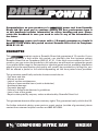
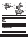
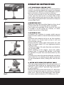
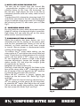
SAFETY AND OPERATING MANUAL
8
COMPOUND MITRE SAW
BM210J
Congratulations on your purchase of a
power tool from Screwfix
Direct Ltd. We want you to continue getting the best performance from it
so this handbook includes information on safety, handling and care. Please
retain this handbook in case you need to refer to any of the information in
the future.
power tool comes with a 12-month guarantee,so should it
Your
develop a fault within this period contact Screwfix Direct Ltd on Freephone
0500 41 41 41.
GUARANTEE
This
product carries a Screwfix Direct Ltd guarantee of 12 months. If your
product develops a fault within this period, you should,in the first instance contact
Screwfix Direct Ltd on Freephone 0500 41 41 41. If the fault occurs within the first 12
months, you may return the goods for a full refund or we will repair or replace the goods
if you prefer. When repair is not practical or identical goods are not available, alternative
goods of similar specification and quality will usually be provided but, failing this, you
will be offered a partial or full refund depending on the time period since purchase.
This guarantee specifically excludes losses caused due to:
- Fair wear and tear
- Misuse or abuse
- Lack of routine maintenance
- Failure of consumable items (such as batteries)
- Accidental damage
- Cosmetic damage
- Failure to follow manufacturer’s guidelines
- Loss of use of the goods
- Repairs attempted by anyone, unless authorised by Screwfix Direct Ltd.
This guarantee does not affect your statutory rights.This guarantee is only valid in the UK.
For further technical advice, spare parts or repair service (outside of guarantee) please
contact the customer helpline number on 0845 607 6380.
8
COMPOUND MITRE SAW
BM210J
SAFETY INSTRUCTIONS
WARNING! Read all instructions.Failure to follow all instructions listed
below may result in electric shock, fire and/or serious injury.
SAVE THESE INSTRUCTIONS
1.
2.
3.
4.
5.
6.
7.
8.
9.
10.
11.
12.
13.
14.
Keep the work area clean.
Cluttered areas and benches invite injuries.
Consider work area environment.
Do not expose power tools to rain. Do not use power tools in damp or wet
locations. Keep the work area well lit. Do not use power tools where there is risk
to cause fire or explosion.
Guard against electric shock.
Avoid body contact with earthed or grounded surfaces (e.g. Pipes, radiators,
ranges, refrigerators, other metal surfaces).
Keep children away.
Do not let visitors touch the tool or extension cord. All visitors should be away
from area.
Store idle tools.
When not in use, tools should be stored in a dry, high or locked up place, out of
reach of children.
Do not force the tool.
It will do the job better and safer at the rate for which it was intended.
Use the right tool.
Do not force small tools or attachments to do the job of a heavy-duty tool. Do not
use tools for purposes not intended, for example, do not use circular saws to cut
tree limbs or logs.
Dress properly.
Do not wear loose clothing or jewellery, they can be caught in moving parts.
Rubber gloves and non-skid footwear are recommended when working outdoors.
Wear protecting hair covering to contain long hair.
Use safety glasses.
Also use face or dust mask if the cutting operation in dusty.
Connect dust extraction equipment.
If devices are provided for the connection of dust extraction and collection facilities,
ensure these are connected and properly used.
Do not abuse the cord.
Never carry the tool by the cord or yank it to disconnect it from the socket. Keep the
cord away from heat, oil and sharp edges.
Secure work.
Use clamp or a vice to hold the work. It is safer than using your hand and frees
both hands to operate the tool.
Do not overreach.
Keep proper footing and balance at all times.
Maintain tool with care.
Keep cutting tools sharp and clean for better and safer performance. Follow
instructions for lubrication and changing accessories. Inspect tool cord
periodically and if damaged have it replaced by an authorised service facility.
Inspect extension cords periodically and replace if damaged. Keep handles dry,
clean and free of oil or grease.
15. Disconnect tools.
When not in use, before servicing and when changing accessories such as blades,
bits and cutters, remove the mains plug from the socket.
16. Remove adjusting keys and wrenches.
Make the habit of checking to see that keys and adjusting wrenches are hat keys
and adjusting wrenches are removed from the tool before turning it on.
17. Avoid unintentional starting.
Do not carry a plugged-in tool with a finger on the switch. Ensure switch is in the
off when plugging in.
18. Use outdoor extension leads.
When tool is used outdoors, use only extension leads approved for outdoor
use.
19. Stay alert.
Watch what you are doing. Use common sense. Do not operate tool when you
are tired or under the influence of drugs or alcohol.
20. Check damaged parts.
Before further use of the tool, a guard or other part that is damaged should
be carefully checked to determine that it will operate properly and perform its
intended function. Check for alignment of moving parts, free running of moving
parts, breakage of parts, mounting and any other conditions that may affect its
operation. A guard or other part that is damaged should be properly repaired
or replaced by an authorised service centre unless otherwise indicated in this
instruction manual. Have defective switches replaced by an authorised service
facility. Do not use the tool if the switch dose not turn it on and off.
21. Warning.
The using of any accessory or attachment, other than those recommended
in this instruction manual may present a risk of personal injury.
22. Have your tools repaired by qualified person.
This electrical tool is in accordance with the relevant safety requirements.
Repairs should only be carried out by qualified persons using original spare
parts, otherwise this may result in considerable danger to the user.
8
COMPOUND MITRE SAW
BM210J
ADDITIONAL SAFETY INSTRUCTIONS FOR YOUR MITRE
SAW
1.If the supply cord is damaged have it replaced by a qualified person.
2. Only wood or products such as medium density fibre board can be cut with this
saw. Other materials may shatter or cause the blade to grab.
3. Never fit substandard blades to the saw. Only fit correctly sized saw blade.
4. Let the blade reach full speed before commencing the cut.
5. Do not use damaged or worn blades.
6. Ensure that the directional arrow marked on the blade corresponds with the
rotational direction of motor.
7. Ensure that the movable guards operate freely without jamming.
8. Never cut pieces too small to be held securely against the straight guide leave
enough space for the hand to be a safe distance from the blade.
9. Regularly check the blade securing bolt.
10. Do not run the machine with any part of the casing missing or damaged.
11. Do not start the saw when the blade is inserted into the workpiece.
12. Let the blade come to a complete stop before removing any jammed or offcut
material from around the blade area.
Do not attempt to stop the blade by placing sideways pressure on the blade disc.
13. Before cutting let the saw blade run freely for a few seconds. If it makes an
unfamiliar sound or vibration switch it off immediately and disconnect from the power
supply. Investigate cause or consult your dealer.
14. Ensure all securing clamps are tight and check for excessive play.
15. Never try to cut freehand. Always ensure that the workpiece is securely pressed
against the straight guide and table support surface.
16. Disconnect from the mains supply, pull down the handle of the saw. With the
blade in its furthest down position, rotate the blade by hand to ensure it is free from
obstruction. Repeat this procedure at all maximum mitre and bevel positions before
commencing work.
17. Ensure that the workpiece to be cut off has sufficient room to move sideways.
Failure to do so may result in the off cut binding against the blade.
18. Ensure that irregular or round piece to be cut off has sufficient room to move or
twist so that they cannot pinch the blade.
19. Do not forget to remove any adjustment keys, spanners and wrenches before
switching on the tool.
20. When the machine is in operation, keep hands away from the cutting area.
21. Always ensure the safety guard is in working order before use. Should the guard
not close quickly over the saw blade, do not use.
22. Do not tie or wedge open the safety guard.
23. Only use blades with the correct bore size for the spindle.
24. Do not use saw blade which does not comply with the characteristics specified in
these instructions.
25. Do not use saw blades made of high speed steel.
26. Do not cut into screws or nails. Inspect workpiece for nails and screws before use.
27.Use a Residual Circuit Breaker on all 230V Power tools. This can help minimise the
risk of an electrical shock if an earth fault or short circuits occurs.
28. If using a power cable extension ensure that the cable is fully unwound and that its
length is less than 30m. Lengths over 30 m will effect the tools performance as a result
of voltage drop.
29. Always use the appropriate safety equipment that is required for the product. e.g.
Goggles / Safety Spectacles, Ear defenders (essential with tools with a noise rating of
over 85 dbA), Gloves and face masks. In all cases ensure that the safety equipment is
in good condition.
Double insulation:
The tool is double insulated. This means that all the external metal parts are
electrically insulated from the mains power supply. This is done by placing insulation
barriers between the electrical and mechanical components making it unnecessary
for the tool to be earthed.
Important note:
Remove the main plug from socket before carrying out any adjustment or servicing.
Ensure your mains supply voltage is the same as your tool rating plate voltage.
SYMBOLS
Read the manual
Warning
Wear gloves
Wear dust mask,eye & ear protection
8
COMPOUND MITRE SAW
BM210J
1 SAFETY RELEASE LEVER
2 HANDLE
3 TRIGGER
4 MOTOR
5 SAWBLADE
6 RETRACTABLE SAFETY GUARD
7 FENCE
8 ROTARY TABLE
9 BASE PLATE
10 LOCKING SCREWS FOR STRAIGHT GUIDE
11 ROTARY TABLE SLOT
12 ROTARY TABLE ANGLE SCALE
13 HEAD TILT CLAMPING KNOB
14 RETRACTABLE SAFETY GUARD ACTUATOR
15 BLADE COVER
16 LOCK PIN
17 ROTARY TABLE LOCKING KNOBS
18 DUST EXTRACTION PORT
19 TILT ANGLE SCALE (SEE FIG7)
20 SAFETY GUARD MOUNTING PLATE
21 BLADE LOCK LEVER
22 SUPPORT FOOT
TECHNICAL DATA
Voltage:
230V~50Hz
1200W
Input power:
-1
5,000min
No load speed:
Cutting capacity (Bevel/Mitre)
Straight cut 0° X 0°
120 X 60mm
45° Mitre cut 0° X 45°
80 X 60mm
45° Bevel cut 45° X 0°
120 X 35mm
Compound cut 45° X 45°:
80 X 35mm
6.9kg
Net weight:
NOISE AND VIBRATION DATA
Sound pressure level:
Sound power level:
93.2dB (A)
106.2dB (A)
1.408m/s2
Vibration level:
SAW BLADE:
210mm diameter
30mm bore diameter
2.6mm thickness blade tooth
This saw comes with a 24 Teeth Tungsten Carbide Tipped Blade. Saw blades
are available with differing number of teeth so choose according to the
quality of cut required eg more teeth for finer cut.Always use blades with
the dimensions shown above.
ACCESSORIES
Spanner:
Dust Bag:
Allen Key:
8
1pc
1pc
1pc
COMPOUND MITRE SAW
BM210J
OPERATION INSTRUCTIONS
1.FIT ADDITIONAL SUPPORT FEET
In order to further stabilize the unit and prevent
excess movement should the head be released
accidentally you MUST fit the additional support
feet to the rear of the base plate as follows:
Turn the unit around so you are facing the back
of the saw.The feet mount on either side of the
base plate.Locate and secure the feet using the
two screws provided.Check and confirm they are
secure.(See Fig 2)
Fig 2
2.MOUNTING BOLT
2
Before use, the saw should be fixed to a firm, level
surface with the 2 mounting bolts (supplied).
Four holes are provided in the base of the saw
to enable it to be fixed to a bench, or other
supporting surface. (See Fig3)
3.TO MAKE A CUT
Fig 3
Fig 4
a.Connect the machine to power outlet ensure
that the mains cable is clear of the blade and base
plate.
b.Position the material to be cut on the machine
bed, ensure it is firmly held so that it will not
move during cutting.
Ensure that the rotary table lock knobs (17) and
head tilt clamp knob (13) are tightened before
cutting. (Fig1)
c.Press the trigger (3) and allow the saw blade to
run up the speed.
d.Still holding in the trigger, press the safety
release lever (1) towards the handle. It will then
be possible to push the saw head down by the
handle.
e.Continue to move the saw head down smoothly
and make the cut exerting only gentle pressure
on the downward stroke, letting the saw do the
work.
4. MITRE CUTS USING THE ROTARY TABLE
Fig 5
The saw can be moved from the normal cross cut
0o position (See Fig4) to an angle position up to
45o left or right of the 0o position (Fig5 shows 45o
to left position).
Release the rotary table lock knobs (17). Move the
saw to the desired angle by twisting so that the
table turns. Set at the desired angle, and tighten
the rotary table lock knobs (17). Make your cut.
5. BEVEL CUTS USING THE HEAD TILT
The saw can be moved from the normal 90o
- perpendicular position of Fig4 to an angled
position down to 45o from the horizontal, on
the left only. Fig6 shows the saw in the 45o to
horizontal position (with the rotary table in the 0
position).
To adjust head tilt, release the clamping knob (13)
and tilt the saw head to the left, until the desired
angle is reached on the angle scale (21). Retighten
the clamping knob (13) and make your cut (See
Fig7).
Fig 6
6. COMPOUND ANGLE CUTS
By using both the rotary table adjustment and the
head tilt, cutting of compound angles is possible.
Fig8 shows the saw with 45o set on the rotary
table and the saw head tilted 45o.
7. PRECISION SETTING OF ANGLES
While the machine has been factory set, it is
advisable that the 0o setting of the rotary table
and the 90o perpendicular setting of the tilt be
checked, as these positions may have moved
in transit. (Ensure power is disconnected while
making these adjustments).
To confirm the 0o rotary table setting, set the
rotary table at 0o and tighten the rotary table lock
knob. Check that the angle between the straight
guide and the blade is 90o using a try square
(A, not supplied) as shown in Fig9. If the angle
requires adjustment, loosen the straight guide
clamp screws (10), and align the straight guide
(7) against the try square.
Retighten the clamp screws (10).
Similarly, check that the angle of the blade to the
face of the rotary table is 90o. If necessary adjust
the tilt angle of the saw head at the 90o position
by altering the set screw (23) position.
When the 90o position is correct, tighten the
locknut on the set screw (24). Refer Fig7, Fig10
and Fig11.
The 45o bevel tilt should also be adjusted use a
45o set square or mitre gauge (B, not supplied),
to check the 45o angle, then adjust the set screw
(19) to set the correct stop position, then tighten
the lock screw (20). Refer Fig11 and Fig7.
Fig 7
Fig 8
Fig 9
8
COMPOUND MITRE SAW
BM210J
Fig 10
Fig 11
Mounting
Plate
Fig 12
Loosen
Slightly
Fig 13
8. DUST EXTRACTION PORT
To reduce build up of saw dust and maintain top
efficiency of cutting, the saw may be connected
to a workshop vacuum cleaner via the dust
extraction port (18). The port accepts 32mm
diameter vacuum hose. Alternatively saw dust
collection can be achieved by clipping a dust bag
on the dust extraction port.To ensure optimal dust
collecting, empty the dust bag when it becomes
filled to approximately 2/3 of its capacity.To empty
the dust bag, remove from the dust extraction
port, open the dust bag by unzipping the slide
fastener.
9. CHANGING THE SAW BLADE
Disconnect the saw from the power supply.
Remove the screw on lower left of guard mounting
plate and loosen slightly the other screw on upper
right of mounting plate then slide along the slot
and turn the mounting plate to rest the retractable
safety guard on the top of the upper blade guard.
(See Fig12 &13)
Press blade lock button and rotate blade until
it is locked, then loosen and remove the blade
securing bolt, and outer flange
with the socket wrench provided. (See Fig14)
Note: Blade securing bolt has a left hand thread.
Remove the blade, (See Fig15) (we recommend
the use of a stout glove for this). Clean any saw
dust and debris from the arbor and saw blade
securing flanges.
To refit the blade follow the above procedure in
reverse order. If you take the inner flange off to
clean re-fit as shown in Fig16.
MAINTENANCE
1.Keep the machine’s air vents unclogged and
clean at all times.
2.Remove dust and dirt regularly from the
machine. Cleaning is best done with compressed
air or a rag.
3.Re-lubricate all moving parts at regular
intervals.
4.Never use caustic agents to clean plastic parts.
ENVIRONMENTAL PROTECTION
Waste electrical products should not be
disposed of with household waste. Please
recycle where facilities exist. Check with
your Local Authority or retailer for recycling
advice.
PLUG REPLACEMENT
The fuse in the main plug of your power tool
should always be replaced with one of identical
rating.
Fig 14
Check the voltage given on your power tool
matches the supply voltage.
The power tool is supplied with a fitted plug,
however if you should need to fit a new plug
follows the instruction below.
IMPORTANT
The wire in the mains lead are coloured in
accordance with the following code:
Fig 15
Blue ---Neutral
Brown ---Live
The wire that is coloured blue must be connected
to the terminal that is marked with the letter N.The
wire that is coloured brown must be connected
to the terminal that is marked with the letter L.
A 13AMP (BS1363 or BS1363/A) plug must be
used and a 13 AMP fuse must be fitted.
Fig 16
13 AMP
FUSE
BLUE
N (NEUTRAL)
OUTER
SLEEVE
8
BROWN
L (LIVE)
CABLE GRIP
COMPOUND MITRE SAW
BM210J
Declaration of Conformity
We, Importer
Screwfix Direct Ltd
Mead Avenue
Houndstone Business Park
Yeovil
BA 22 8RT
Declare that the product
MITRE SAW
BM210J
Complies with the essential health and safety requirements of the following directives:
89/336 EEC, 93/68 EEC.–EMC Directive.
73/23 EEC, 93/68 EEC.–Low Voltage Directive
98/37 EC.–Machinery Directive.
Standards and technical specifications referred to:
EN 61029-1:2000
EN 61029-2-9:2002
EN 55014-1:2000/+A1:2001/+A2:2002
EN 55014-2:1997/+A1:2001
EN 61000-3-2:2000
EN 61000-3-11:2000
Authorised Signatory
Date:
03/15/05
Signature:
Name: Peter Harries
Screwfix Direct Ltd
Quality Manager
2005
8
COMPOUND MITRE SAW
BM210J