1
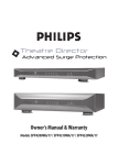
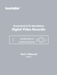
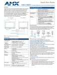
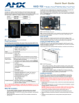
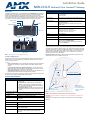
Installation Guide
NXB-CCG-K NetLinx® Clear Connect™ Gateway
Overview
NXB-CCG-K (FG2606-868) Specifications (Cont.)
The NXB-CCG-K NetLinx Clear Connect Wireless Gateway (FG2606-868) connects NetLinx
Controllers with Lutron's Clear Connect Occupancy Sensors. The Gateway includes a web
interface for simplified integration, configuration, and programming of Clear Connect
devices. When integrated with an AMX NetLinx Controller, installers now have a simple and
cost-effective path to offer smart room automation that includes light and AV control from a
single interface, occupancy sensing, scheduled shutdown and energy management.
Operating Environment:
• 32 °F to 104 °F (0 °C to 40 °C), 0% to 90% humidity,
non-condensing.
• Indoor use only.
ESD Protection:
ESD protection to withstand electrostatic discharge without
damage or memory loss, in accordance with IEC 61000-4-2.
Communications:
• The NXB-CCG-K communicates to other Clear Connect
devices through RF.
• All devices must be located within 30 feet (9 m) of the
NXB-CCG-K.
Auto Discovery:
Supports the ZeroConf auto discovery protocol.
Dimensions (HWD):
• Without antenna: 1” x 2 9/16” x 4 7/16”
(25.4 mm x 65.1 mm x 112.7 mm)
• With antenna: 3 2/16” x 2 9/16” x 4 7/16”
(79.4 mm x 65.1 mm x 112.7 mm)
Ethernet LED
RF LED
Antenna
Power/Status LED
1”
(25.4 mm)
USB Cable
5VDC Power
CAT5 Cable Port
Jack
Reset
Port
Button
Weight:
0.3 lbs (136.08 g)
Certifications:
• CE
Included Accessories:
• NXB-CCG-K Installation Guide (93-2606-68)
Other AMX Equipment:
• CCD3-OCRB-P-WH, 868 MHz Ceiling Mount Occupancy/
Vacancy Sensor (FG2606-44-WH)
• PS-CCG 5 VDC, 3A Power Supply With 2.1mm Barrel
Connector (FG423-61)
Important Notes
2.56”
(65.1 mm)
FIG. 1 NXB-CCG-K ClearConnect Wireless Gateway
Proper orientation of the antenna helps ensure maximum range and the best performance.
The NXB-CCG-K should be positioned centrally to the devices being controlled, and as high
and clear of obstructions as possible. The NXB-CCG-K utilizes an omni-directional antenna,
which produces a circular pattern perpendicular to the antenna. For best performance, the
antenna should be positioned vertically (tip up or down, not sideways). Try to keep the
antenna at least 2 feet from metallic objects.
RF Device Placement: All dimmers, switches, keypads and shades / draperies must be
located within 30 ft (9 m) of the NXB-CCG-K (FIG. 2).
Common Applications
The NXB-CCG-K is ideal for new and retrofit applications looking for the least costly way to
add AV control to a room. The NXB-CCG-K is designed to interface with Lutron's Clear
Connect Occupancy Sensors.
NXB-CCG-K
Features
•
Clear Connect Enabled – Lutron's patented RF Technology uses a quiet band that is
essentially free of interference, ensuring reliable communication between system
devices
• Create Light & Control Events with Room Occupancy – Use the Clear Connect
Wireless Occupancy Sensor with RMS to automatically power-up and shut down the
lights and AV equipment to maximize energy conservation
• Simple Web Configuration – Browse to the NetLinx Clear Connect Gateway URL to
quickly add Clear Connect Enabled Occupancy/Vacancy Sensors
The NXB-CCG-K can control up to 31 devices at a time, and can configure up to ten devices
at a time up to that maximum through its Web Interface Pages.
Power Source
30 feet (9 m) maximum
Product Specifications
NXB-CCG-K (FG2606-868) Specifications
Power Requirements:
• Power Input: 600mA @ 5VDC, DC adapter optional
(5V DC, 3A).
• Surge Protection: To withstand surge voltages without
damage or loss of operation, in accordance with IEEE
C62.41-1991 Recommended Practice on Surge Voltages in
Low-Voltage AC Power Circuits.
• Power Failure Memory: Should power be interrupted, the
NXB-CCG-K will return to its previous state when power is
restored.
Front Panel Components:
Power/Status LED:
Displays power status and other system status indicators.
RF LED:
Displays the Tx / Rx activity on the RF link.
Ethernet LED:
Displays the connection status and Tx / Rx activity on the
Ethernet link.
Rear Panel Components:
CAT5 Cable Port:
Maximum cable length: 328 ft (100 m)
USB Cable Port:
Manufacturer use only.
Reset Button:
Press and hold for 20 seconds to restore the system to the
Factory Default settings.
Power Jack:
(IEC PELV / NECR Class 2). This product should be
connected to a safety isolating supply conforming with
EN61558.
Lutron Occupancy Sensors
Note: Antenna
position for clarity
only. Antenna should
always be installed
upright.
FIG. 2 RF Configuration of NXB-CCG-K and Occupancy Sensors
Codes: Install in accordance with all local and national electrical codes.
WARNING: Using a DC adapter not rated at the proper specifications could damage the
NXB-CCG-K.
Cleaning: To clean, wipe with a clean damp cloth. DO NOT use any chemical cleaning
solutions.
Installation
Web Interface Pages
1.
Find a suitable location for the NXB-CCG-K.
NOTE: Proper orientation of the antenna helps ensure maximum range and the best
performance. The NXB-CCG-K should be positioned centrally to the devices being
controlled, and as high and clear of obstructions as possible. For best performance, the
antenna should be positioned vertically (tip up or down, not sideways). Try to keep the
antenna at least 2 feet from metallic objects.
2.
Mount vertically or horizontally (FIG. 3), using two #6 (M3) screws. When mounting,
allow 7 in (177.8 mm) clearance for the antenna and ensure convenient access to the
power plug. In order to achieve proper RF performance, do not mount unit in a metal
enclosure.
3.
Attach the DC adapter cord to the power jack on the NXB-CCG-K and insert the DC
adapter plug into a receptacle.
NOTE: This product contains licensed software; see the SOFTWARE NOTICES AND
LICENSES link on the Web interface login screen for software notices and license
information.
The NXB-CCG-K feature a built-in zero-configuration networking client that allows you to
determine the unit’s IP address via NetLinx Studio v3.0 (or higher), or a similar zeroconfiguration client or browser. Entering the device’s IP address in an enabled browser
(Mozilla Firefox and Apple Safari for PCs and Firefox and Safari for Macintoshes) allows the
device to be accessed in that browser. Once contact is established, and a username and
password entered, the Web interface pages may be reached and updated.
Zero-configuration (or Zero-Config) technology provides a general method to discover
services on a local area network. In essence, it allows you to set up a network without any
configuration.
Accessing the Web Interface Pages
Underside
of NXB-CCG-K
Vertical
2.62”
(6.70 cm)
To access the Web interface pages:
1.
From any computer or Netbook that has access to the LAN on which the NXB-CCG-K,
open a web browser and type the IP address of the target NXB-CCG-K unit in the
Address Bar.
2.
In the Login page, enter your username and password. (The default username and
password are admin and 1988.)
Configuring the NXB-CCG-K
Once logged in, the Web interface automatically opens to the Settings tab of the Configure
page. From here, the administrator may access other tabs and pages to add or change Web
and integration logins and passwords, change network or security settings, add devices to a
network, or control the programming of buttons on an individual device.
Wall
Horizontal
Level Surface
1”
(2.54 cm)
FIG. 3 Installation Diagram
4.
Use CAT5 Ethernet cable to connect the NXB-CCG-K to the chosen network’s
Master. Please refer to the Ethernet Pin Numbering diagram (FIG. 4) for the correct
connection.
Returning an NXB-CCG-K to Factory Default Settings
Note: Returning an NXB-CCG-K to factory default settings will erase all programming from it
and will require the device to be reprogrammed into the system. Devices connected to the
NXB-CCG-K will need to be reset separately to their factory defaults before they can be
reconnected.
1.
Press and hold the Reset button (FIG. 1) on the device for 20 seconds.
2.
The Power/Status LED will start flashing slowly for approximately10 seconds, after
which it will start rapidly flashing for approximately 20 seconds and then remain on.
3.
The device has been returned to its factory default settings.
Adding Integration Logins
To add a new user login:
1.
From the Configure page, select the Integration Logins tab.
2.
Click the New Integration Login button.
3.
Enter the new username and password and click Create.
NOTE: The user login must be alphanumeric, with no spaces or punctuation.
4.
The new username will appear in the Integration Logins tab.
Changing Integration Passwords
To change a user’s password:
1.
From the Configure page, select the Integration Logins tab.
2.
In the appropriate user entry, select Change Password.
3.
Enter the new password and click Change.
4.
The new password is now enabled.
Removing Integration Logins
To remove a user login:
1.
From the Configure page, select the Integration Logins tab.
2.
In the appropriate user entry, select Delete User.
3.
Confirm that you wish to remove this user by clicking Yes.
For more information on using the Web interface pages, please refer to the NXB-CCG-K
Operation Reference Guide, available from www.amx.com.
Ethernet Pin Numbering
The numbering for pins in the Ethernet port is as follows:
Ethernet Pin Numbering
Ethernet:
Pin #:
T+Ve
1
T-Ve
2
R+Ve
3
R-Ve
6
FIG. 4 Ethernet Pin Numbering
For full warranty information, refer to the AMX Instruction Manual(s) associated with your Product(s).
2/13
©2013 AMX. All rights reserved. AMX and the AMX logo are registered trademarks of AMX.
AMX reserves the right to alter specifications without notice at any time.
3000 RESEARCH DRIVE, RICHARDSON, TX 75082 • 800.222.0193 • fax 469.624.7153 • technical support 800.932.6993 • www.amx.com
93-2606-68
REV: A