1
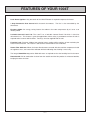
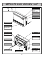
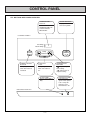
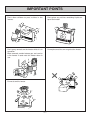
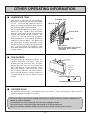
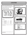
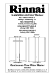
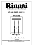
Installation and User Manual
RHFE-1004T
Ñ
Energysaver Space Heater
Important.
Read these instructions carefully before attempting installation or use of
this appliance. All work must be carried out by competent persons.
Rinnai Corporation - Japan
ISO 9001
APPROVED BY JIA
Manufactured under a
Quality System Certified
as complying with ISO
9001 by an Accredited
Certification Body.
CONTENTS
Features of your 1004T ……………………………………………………………………………………2
Getting to know your New 1004T …………………………………………………………………………3
Control Panel Layout ………………………………………………………………………………………4
Important Points ……………………………………………………………………………………………5
Customers Operating Information
How to operate the Heater …………………………………………………………………………………7
Adjusting Temperature………………………………………………………………………………………8
Economy Mode………………………………………………………………………………………………8
Function Lock ………………………………………………………………………………………………9
Other Operating Information………………………………………………………………………………10
Installation
Location ……………………………………………………………………………………………………11
Installation Instructions ……………………………………………………………………………………14
Making Electrical Connection ……………………………………………………………………………15
Wiring Diagram for Programmer …………………………………………………………………………16
Summary of Position for Terminal ………………………………………………………………………17
Installation Instructions ……………………………………………………………………………………18
Using the Template ………………………………………………………………………………………19
Sleeve and Manifold Installation …………………………………………………………………………20
Fitting Unit …………………………………………………………………………………………………21
Forced Flue Heater Extension Kits ………………………………………………………………………24
Testing ………………………………………………………………………………………………………29
Gas Pressure Setting Procedure…………………………………………………………………………30
Gas Conversion Procedure ………………………………………………………………………………31
Care of your 1004T ………………………………………………………………………………………32
Pre-service Check …………………………………………………………………………………………33
Error Messages ……………………………………………………………………………………………34
Safety Devices ……………………………………………………………………………………………35
Product Specifications
Dimensions …………………………………………………………………………………………………36
Wiring Diagram ……………………………………………………………………………………………37
Warranty ……………………………………………………………………………………………………38
Specifications ………………………………………………………………………………………………39
Service Contact Points ……………………………………………………………………………………39
–1–
FEATURES OF YOUR 1004T
Push Button Ignition: Only one touch of the ON/OFF button is required to operate the heater.
7 Step Automatic Heat Control with electronic thermostat. The fan is also controlled by the
thermostat.
Economy Mode: An energy saving feature that reduces the room temperature by 3˚C over a 90
minute period.
Lockable Control Panel Lid: The 1004T has a lockable Control Panel Lid which is ideal for
commercial use. This feature is great for applications where safety is paramount or when the unit is
required to be set once and left alone. Two keys are also supplied with the unit.
Function Lock: Prevents children from altering heater settings whilst running, or from activating the
heater when turned off. This feature is utilised if the Control Panel Lid is unlocked.
Heater Filter Indicator: When the heater filter becomes covered with dust and the temperature inside
the appliance rises, the heater filter indicator will flash indicating that cleaning is necessary.
The integral humidifier tray can be filled with water as required to raise the humidity level in the room.
Room Sealed: Air for combustion is taken from the outside and the flue product is exhausted outside,
keeping the room air clean.
–2–
GETTING TO KNOW YOUR NEW 1004T
Filt er
oN
CONTROL PANEL
OPERATION/TEMPERATURE
CONTROL DISPLAY
FILTER INDICATOR
OPERATION
INDICATOR
WARM AIR OUTLET
HUMIDIFIER
OPEN THE DOOR
AND POUR WATER
INTO THE TRAY.
GAS CONNECTION
AIR FILTER
1/2" BSP (15mm)
FLUE TERMINAL
THERMISTOR
EXHAUST PIPE
POWER CORD
RATING PLATE
PLUG 230VAC
COMBUSTION AIR
INTAKE HOSE
–3–
MODEL NUMBER,
SERIAL NUMBER,
GAS TYPE, ETC.
CONTROL PANEL
ALL BUTTONS BEEP WHEN OPERATED.
TEMPERATURE
DISPLAY
SHOWS EITHER THE
TEMPERATURE OR
CODED ERROR
MESSAGES.
ON/OFF BUTTON
Easy operation
One touch ignition
〈CONTROL PANEL〉
Set Temp
Room Temp
Economy
Temp
Control
ON/OFF
Function Lock
ENERGY SAVING
BUTTON
Lamp is “green”
when this feature is
activated.
FUNCTION
LOCK
Lamp is “green”
when this feature is
on.
FILTER LAMP
Flashes when filter is
dirty.
TEMPERATURE
BUTTONS
“
” adjust temp. to
lower setting.
“
” adjust temp. to
a higher setting.
OPERATION LAMP
This lamp turns
“green” when power
is on. Lamp will
change to “red”
when burner is on.
〈INDICATOR DISPLAY〉
Filter
–4–
ON
IMPORTANT POINTS
Do not use for any other purpose except
heating.
These clearances should be maintained at all
times.
250mm
50mm
50mm
1000mm
Keep flammable materials, trees shrubs etc.
away from flue terminal.
Do not allow cur tains or other flammable
materials to come into contact with the heater.
LP GAS
Flue Terminal
Do not store flammable products near the unit.
Supervise children near heater.
Do not allow young children or the infirm to
sleep directly in front of the heater.
–5–
IMPORTANT POINTS
Don’t allow children to ‘post’ articles in the
louvres.
Don’t place any articles containing liquids on
top of the heater.
Don’t spray aerosols on the heater whilst it is in
operation.
Most aerosols contain butane gas and can be
a fire hazard if used near this heater when in
use.
Do not place articles on or against the heater.
Do not sit on this heater.
–6–
HOW TO OPERATE THE HEATER
■ Turning ON
●Press the ON/OFF button
・The ON indicator will illuminate green.
・The combustion fan will rotate.
・Ignition will take 5〜10 seconds and the
ON/Combustion indicator will change from
green to red to let you know that the
burner has ignited.
ON / OFF
Note:
・When using the unit for the first time or after long periods of disuse, ignition may not occur the first time
it is operated as there may be air in the gas pipes. If ignition does not occur after approximately 30
seconds the unit will cease operation automatically.
Try operating the unit again if this occurs.
・The unit may make noises after ignition/extinction. This is the inside of the unit expanding and
contracting and is normal.
・The heater will not ignite if the “ON/OFF” button is pressed straight after extinction. After
approximately 20 seconds has passed the unit will automatically go back into ignition mode.
■ Turning OFF
●Press the ON/OFF button
・The ON/Combustion indicator will go out.
・ After the indicator has gone out, the
convection fan will continue to rotate for
several minutes, then stop. This is to
lower the temperature within the unit. Do
not pull out the power cord during this
time.
ON / OFF
CAUTION !
・Do not pull out the power cord or disconnect the power during combustion to cause extinction, or
straight after extinction, as this may cause damage to the unit.
When the Function Lock is set, the Function Lock indicator will continue to illuminate even when the unit
is OFF and the Function Lock will not be cancelled.
–7–
ADJUSTING THE TEMPERATURE
Displaying, setting and adjusting the room temperature can
only be done when the heater is operating.
・When the unit is first operated, the room temperature is
set at 22˚C.
・Set the desired room temperature with the up and
down buttons while looking at the display section.
・The “Set Temp” can be set to “L” or between “12” 〜
“26”, or “H” (continuous combustion on High).
・The “Room Temp” will display “L” (when lower than
1˚C), “1” 〜 “30” (at intervals of 1˚C), or “H” (when
higher than 30˚C).
・Once a temperature is set, it will be stored in the
microcomputers memory.
Set Temp
Room Temp
Temp
・
Time
Function Lock
Note:
Press to lower
the temperature
・Rooms may not arrive at the set temperature due to the
construction of the room, the location of the unit, or
external temperatures.
Press to raise
the temperature
If the heater does not ignite then the pre-set temperature may not be set to a temperature which is
higher than the actual room temperature.
ECONOMY MODE
The Economy Mode, when selected, has the ability to reduce gas consumption and ultimately save energy.
Once a room has reached the desired temperature, the unit will automatically begin reducing the set
temperature gradually. This reduction is normally not noticeable, however, it is purely your choice whether to
select this mode or not.
How it works
・After a room reaches the set temperature, the set room temperature will decrease 3 times automatically,
each time, dropping by a maximum of 1˚C in 30 minute blocks. From the second time onwards, the comfort
control will automatically operate. (The comfort control alters combustion and fan speed more frequently to
counteract the feeling of cold air.)
・The Economy indicator will illuminate to let you know that the Economy Function is selected.
・The Economy function will not operate when the set room temperature is less than 16˚C or above 26˚C.
・When the Economy function is operating, the current displayed room temperature may be lower than the
set room temperature, however, this is normal.
Set
Room
Temp
Max. 1℃
Max. 1℃
Max. 1℃
30min
30min
30min
Comfort Control
"Economy" indicator illuminates
–8–
FUNCTION LOCK
The Function Lock will help to prevent accidental operation as well as small children from altering the
heater settings.
Set Temp
1
Room Temp
The Function Lock can be operated either when the
heater is running, or in the “stand by” mode, by
pressing the up and down buttons simultaneously.
The Function Lock is activated and the Function Lock
indicator will glow.
Temp
・
Time
Function Lock
Set Temp
2
Room Temp
To de-activate the Function Lock, simply press both
arrow buttons simultaneously for 2 seconds and the
Function Lock indicator will go out. The lock can be
de-activated at any time in this way.
Temp
・
Time
Function Lock
When the Function Lock is activated during normal operation all heater controls other than the OFF
switch will be locked. Deactivating the lock releases the controls. If the lock is activated whilst the
heater is turned OFF, then all heater functions will be locked. If the heater is turned OFF whilst the
Function lock is activated, it cannot be turned ON again until the lock is deactivated.
–9–
OTHER OPERATING INFORMATION
■ HUMIDIFIER TRAY
Humidifier Tray
Your 1004T is fitted with an enamelled tray
behind the air outlet so that you can humidify
the air. To fill the tray, open the door as
shown in the diagram and pour water into the
tray using the spout built into the door.
The air will be humidified as it passes over the
water in the tray. DO NOT FILL THE TRAY
WHILST THE UNIT IS IN OPERATION.
CLOSE THE DOOR AFTER FILLING. The
1004T is a very high efficiency appliance.
During operation a small amount of water is
produced in the flue tubes. This drains into
the enamel tray. It is quite normal for a small
quantity of water to remain in the bottom of the
tray. If you are using the humidifier, it will
need filling about once a day during the peak
heating season.
Max. Fill Line
Access Door
Pull
Filler Spout
Do not force door open too far.
Close door during heater
operation.
■ FAN FILTERS
Fan Filters
To protect the fan from dust and lint, the
1004T is fitted with 2 fan filters. They are
located at the top, rear of the unit. To clean,
pull the filters out of the unit and remove dust
with a soft brush or a vacuum cleaner. Re-fit
filters after cleaning. Your 1004T has a filter
clean warning indicator that will illuminate
when required, however, weekly cleaning is
recommended during the peak heating
season.
Filter clean
warning
indicator
Filt er
oN
■ OUTSIDE FLUE
On cold days steam may be discharged from the flue outlet. This is normal with a high efficiency
appliance and does not indicate any fault.
The heater and its flue must be installed correctly by an authorised person, and the installation must
conform to all local regulations.
The installation also must comply with the instructions supplied by Rinnai.
This heater must be serviced, installed and removed by an authorised person.
No parts or functions should be modified or permanently removed from the heater or its flue.
– 10 –
LOCATION
When positioning the unit the main points
governing the location are:
This unit is not designed to be built in.
(1) Flueing
(2) Warm Air Distribution.
This heater must not be installed where curtains or
other combustible materials could come into
contact with it. In some cases curtains may need
restraining.
See diagram for other recommended clearances.
250mm
Flue is not designed to be positioned under floors,
or below the level of the heater.
50mm
50mm
1000mm
Flue
Terminal
Flue
Terminal
Flue terminal should be positioned away from
flammable materials.
LP GAS
Flue fittings must be kept clear of flammable
materials.
Flue Terminal
– 11 –
LOCATION
Do not flue into natural draught flues or fireplaces,
this unit can only be used with a Rinnai flue kit.
(A flue kit is available to flue right through to the
rear of most fireplaces Use this kit when the heater
is going to be installed in front of a fireplace.)
Do not flue unit into other rooms.
Flue terminal must be outside.
Standard Installation of flue manifold.
Diagram below shows minimum clearances and
distances from obstructions.
Flammable
600mm
Wall
Non
Flammable
250mm
300mm
600mm
Opposite
Wall
Floor
Side Clearances.
300mm
Flue may be positioned directly under opening
windows with a minimum clearance of 300mm.
Obstruction
Flue sizes:
S
A
B
C
D
E
flue suits walls
flue suits walls
flue suits walls
flue suits walls
flue suits walls
flue suits walls
75
115
240
400
600
800
-
115 mm
240 mm
400 mm
600 mm
800 mm
1000 mm
SNOW AREAS
25mm spacers are available for wall thicknesses
less than 75mm.
Snow
In areas subject to heavy snowfall, keep snow clear
of flue terminal at all times.
For information on special extra long flues, contact
Rinnai UK Ltd.
– 12 –
LOCATION
Do not install the unit in an unusually dusty area.
FOR WEATHERBOARD WALLS DRILL
THROUGH CENTRE OF WEATHERBOARD
FROM OUTSIDE, THEN DRILL FROM INSIDE
THROUGH PLASTERBOARD.
(mm)
54
Use flue guard if the terminal is easily accessible to
children.
Check local regulations.
Flue guards are available as an optional extra.
22
300
50
R2
65
R3
38
465
When drilling the flue hole, check for water and gas
pipes and electric cables before starting to drill.
Use an 80mm (8cm) drill for hole through wall.
;;;;
;;;;
;;;;
;;;;
;;;;
;;;;
;;;;
;;;;
GUARD
¢¢¢
;;;
QQQ
;;;
QQQ
¢¢¢
;;;
QQQ
¢¢¢
;;;;
;;;;
;;;;
;;;;
;;;;
;;;;
;;;;
Floor must be level.
Do not use electrical extension cords to connect
unit to power supply.
Keep the power cord away from the flue.
Flue manifold position.
Centre of hole for flue manifold can be drilled
anywhere within the shaded area.
(To avoid studs etc.)
– 13 –
INSTALLATION INSTRUCTIONS
Important Safety Instructions
1. Gas Safety (Installation & Use) Regulations 1998 are the ‘Rules in Force’.
In your own interest and that of safety, it is law that all gas appliances shall be installed by
competent persons in accordance with the above regulations.
Failure to install appliances correctly could lead to prosecution. Other persons should NOT
attempt to install this equipment.
2. Unpack the appliance and check it carefully. If it appears to have any operating defects DO NOT
INSTALL, but contact the supplier.
3. This appliance is intended to be used to raise the temperature in a room or office etc. You should
NOT use it for any other purpose without seeking advice from the supplier.
4. This appliance is safe if correctly installed and sited. Please comply CAREFULLY with the
instructions.
5. This appliance is to be used for NATURAL GAS (G20) and PROPANE (G31) only. It must NOT
be used with any other type of gas.
6. Installation MUST be carried out in accordance with the current issue of:
a) Building Regulations issued by the Dept. of the Environment and Building Standards (Scotland
Consolidation) Regulations.
b) I.E.E. Wiring Regulations for electrical installations.
c) Gas Safety (Installation and Use) Regulations 1998.
d) BS5871 Part 1:2001
e) BS5440 Part 1:2000 and Part 2:2000
f) BS6891 Part 1:1998 (Natural Gas) and BS5482 Part 1:1994 (Propane).
g) Local Byelaws
h) Children & Young Persons Act 1933 revised 1952
i) Health and Safety at Work etc. Act, 1974
j) Such other specifications or legislation that may have superseded the above documents.
7. Should the heater be fitted in a room where there are young children; elderly; infirm or
handicapped persons, it is strongly recommended that a guard is fixed around the heater.
Guards conforming to British Standard Specification 6778:1986 (Fireguards for Use with Portable
Free Standing or Wall Mounted Heating Appliances) in respect of fixing, strength and painted
finish are acceptable and overall dimensions should be such that there is a gap of at least 100mm
(4 inches) between the guard and the heater. Standard guards that meet these requirements are
available from the supplier.
Please be sure you are aware of the implications of these notes.
– 14 –
MAKING ELECTRICAL CONNECTION
WARNING: This appliance must be earthed.
This appliance is suitable for use on 230V 〜 50Hz mains only and external wiring must be carried out
to I.E.E. Regulations.
Connect the appliance to the mains electrical supply. A 3amp switched fuse spur with contact
separation of at least 3mm on all poles, must be provided as a means of electrically isolating the
heater for servicing purposes.
Observe polarity and that wiring is correctly restrained.
E
L
N
EARTH
LIVE
NEUTRAL
Green / Yellow
Brown / Red
Blue / Black
IMPORTANT
Do not use a clock or any other type of switch on the electrical supply apart from as the means of
isolating the supply for servicing. (A clock or switch in the supply would also turn OFF the convection
fan and allow overheating to take place).
INSTALLATIONS NOT INCORPORATING A REMOTE TIMING DEVICE
When the heater is to be used as a stand-alone unit the central timer sub PCB fitted on the heater has
to be disconnected from the main PCB. Disconnecting terminal plug H (white, red and blue wires), as
indicated on the top wiring diagram of page 37, will enable the heater to operate independent of a
timing device.
Plug H
TIME CONTROL
It is necessary to make the time control electrical connection before the unit is fixed to the wall.
The switch live and neutral wires from any remote timing device must be connected onto the terminal
connector situated on the rear of the appliance. Removing the metal protection cover accesses this
terminal connector block which is indicated in the photograph below. (Wiring diagram Page 37)
Terminal Connector Block
– 15 –
WIRING DIAGRAM FOR PROGRAMMER
For multiple Rinnai appliances using a single time clock.
RINNAI 1004T
RINNAI 1004T
L
N
L
N
RINNAI 556T
L
N
RANDALL 851 TIMER
N
– 16 –
L
POSITIONING THE FLUE TERMINAL
Q
I
Q
Q
P
F
D,E
G
Dimension
N
O
C
M
B
L
N
H
A
I
H
M
J
Terminal Position
K
Distance
A
Directly below an opening, air brick, opening windows, etc.
300mm
B
Above an opening, air brick, opening window, etc.
300mm
C
Horizontally to an opening, air brick, opening window, etc.
300mm
D
Below gutters, soil pipes or drain pipes.
75mm
E
Below eaves.
200mm
F
Below balconies or car port roof.
200mm
G
From a vertical drain pipe or soil pipe.
150mm
H
From an internal or external corner.
200mm
I
Above ground, roof or balcony level.
300mm
J
From a surface facing the terminal.
600mm
K
From a terminal facing a terminal.
1200mm
L
From an opening in a car port. (e.g. door, window) into a dwelling.
1200mm
M
Vertically from a terminal on the same wall.
1500mm
N
Horizontally from a terminal on the same wall.
300mm
O
From the wall on which the terminal is mounted
N/A
P
From a vertical structure on the roof.
N/A
Q
Above an intersection with roof.
N/A
– 17 –
INSTALLATION INSTRUCTIONS
■ The following components are supplied with your 1004T
Flue Manifold .......................1
Spare rubber seal ................1
(For weatherboard installations)
Back Spacer
Set
1
Wall
Brackets
2
Insulation
Clip
1
Plastic tie for
air inlet
1
7
(M4)
Floor
Brackets
For Back Spacer Set
2
(M5)
8
For Wall Brackets
1
Air inlet hose
1
(M4×20)
For Flue Lock Stopper
Exhaust
adaptor
1
3
(M4)
For Flue Manifold
Pipe stopper
A&S
2
Pipe stopper
E
(M4.8×32)
Wood Screws
1
11
Wall Bracket Screws
Instructions
Check unit supplied is correct for the gas type.
Refer to data plate located inside front panel.
Check for damage. If the unit is damaged contact your supplier.
Do not install a damaged unit before checking with your supplier.
– 18 –
1
USING THE TEMPLATE
1. Fold the template along the bottom so that the bottom of the feet are at the edge of the
paper.
2. Tape the template to the wall in the position that the heater is to be installed, with the feet
sitting on the floor.
3. The centre of the flue hole can be located anywhere within the shaded area of the arc. For
ease of installation choose the centre of the arc, in the middle of the shaded area. Other
areas work, but fitting the heater is more difficult. Drill the hole 80mm in diameter.
4. Mark the position of the wall brackets. Before drilling the wall brackets double check the
position of them by putting the heater up against the wall. Holding the wall brackets to the
heater bracket check the position the markings on the wall. Once you are sure the position
is correct drill the holes and fix the brackets to the wall using the screws provided.
– 19 –
SLEEVE AND MANIFOLD INSTALLATION
METHOD FOR STANDARD WALLS
1. Dis-assemble Manifold from Sleeve.
The flue consists of 3 parts, sleeve, inside
connectors and tube, outside terminal; (disassemble by pulling hard on outside terminal
and inner connections, then pull sleeve off outer
terminal).
Connections
Sleeve
Extension joint
under plastic
Extention
Terminal
2. Adjustment of Sleeve Length.
Measure wall thickness through previously
drilled 80mm hole.
End of sleeve should protrude 5-10mm from
outside wall. Adjust sleeve length to wall
thickness plus 5-10mm. (Sleeve is threaded for
adjustment).
(‘A’ and ‘S’ flues only)
Adjust length by turning sleeve.
3. For A and S flues only
Depending on flue set and wall thickness
extension piece ‘C’ may need to be removed.
Cut plastic, remove extension, then follow
instruction 2.
This applies to ‘A’ and ‘S’ flues only.
There is no extention on other flues, they can
be fully adjusted by turning the threaded
section.
A
B
C
Remove extension at this
point if necessary.
4. Fixing Sleeve.
5-10mm
Fix to the wall, using the 3 screws provided.
2°
"TOP"
NOTE:
The flange is marked “TOP”, sleeve must be
fitted with this mark UP.
Check sleeve protrudes 5-10mm on the
outside.
Fixing Screw
Don't remove green plastic covering from sleeve.
– 20 –
SLEEVE AND MANIFOLD INSTALLATION
METHOD FOR STANDARD WALLS
5. Check rubber seal is in place on terminal.
Terminal seal
6. Installation of Terminal
"TOP" mark "A"
Label
From outside, insert terminal into sleeve with
the “A” mark at the top. Left hand side fixing tie
is marked “LEFT” (from inside).
Fixing Tie
Terminal
Cut (leave 20mm free)
7. Attaching Ties
Pull hard on left and right hand side ties, clip
ties over lugs inside sleeve. You should be
able to pull ties 2 or 3 slots past the starting
point. Cut the ties, leaving about 20mm past
the lugs. Bend ties so they are parallel with the
wall.
Pull hard
Fixing tie
Lug
Sleeve
8. Insert Inner Connection Assembly. Push
assembly into the terminal tube, make sure
“TOP” mark is uppermost. Fix with 3 screws
provided.
Terminal
Top Mark
Screw
lnner
Connections
9. Manifold can still be turned after attaching.
Outlet
20˚
Rubber cap
Inlet
– 21 –
FITTING UNIT
Fix Flue Adapter to Flue.
Manifold with Locking Clamp S as shown below.
Air Inlet Hose
Connect Air Inlet Hose to Manifold Inlet.
Do not kink the hose.
Secure with plastic tie as-shown below.
Locking clamp S
Flue Manifold
Plastic tie
Flue Adapter
OUT
Inlet elbow
Inlet hose
Fit Air inlet Hose to heater
Fix Side Back Spacers with screws.
1. Connect the flue outlet tube to the manifold by
extending the stainless steel sliding tube until it
is fully inserted into the manifold.
Flue Manifold
Sliding Tube
Red Line
Air Inlet Hose
Sliding Tube should not be extended beyond
the RED LINE.
2. Fit the Locking Clamp L over connection
between sliding tube and manifold.
Engage the hook and rotate it until it snaps
against the body of the clamp.
Fit Inlet Elbow
Fit a suitable inlet fitting to the male 1/2 inch BSP
threaded fitting on the rear of the heater.
The appliance can then be connected with 15mm
copper tube.
Manifold
Flue outlet
Sliding tube
Hook
Locking
clamp
– 22 –
Locking
Clamp
FITTING UNIT
3. Fit the screw clamp between the sliding tube
and the flue elbow. Secure with the 4mm screw
supplied. The flue outlet is now locked into
position.
4. Slide the insulation sleeve up to the flue
manifold. Slip the securing clip over the sleeve
as shown.
Fit clip
Locking Clamp L
Locking Clamp S
Screw
Slide Insulation sock
Flue Outlet tube
screw clamp
Flue elbow
Fuel outlet
Sliding tube
Flue elbow
Sock
Manifold
– 23 –
Flue outlet
Sliding tube
Slide to here
FORCED FLUE HEATER EXTENSION KITS
EXTENSION SET PARTS AND INSTALLATION GUIDE
FOT - 102
FOT - 103
FOT - 114
FOT - 115
• This extension set is to be used for installations requiring extra distance.
MAXIMUM FLUE LENGTH 7 METRES. REDUCE LENGTH 1 METRE FOR EACH BEND USED.
(E.G. 4 METRES, 3 BENDS)
■ NAMES AND NUMBERS OF PARTS
A
B
FOT-102(290-515mm)
FOT-103(533-1005mm)
AEXHAUST PIPE
FPIPE STOPPER A
IPIPE CLAMP
LSCREW A
GPIPE STOPPER B
JWALL-FIXTURE
MSCREW B
HTOP STOPPER
KNUT
NO RING
BEXHAUST PIPE (STRAIGHT) 1 Metre
A FOT-102(290-515mm)
B FOT-103(533-1005mm)
C FOT-104(533-1005mm)
CAIR INTAKE HOSE
DBENT ELBOW
A
B
A
B
A
B
C
C
D
E
F
G
H
I
J
K
L
M
N
EHOSE JOINT
EXHAUST PIPE
EXHAUST PIPE
EXHAUST PIPE (STRAIGHT)
AIR INTAKE HOSE
AIR INTAKE HOSE
AIR INTAKE HOSE
BENT ELBOW
HOSE JOINT
PIPE STOPPER A
PIPE STOPPER B
TOP STOPPER
PIPE CLAMP
WALL FIXTURE
NUT
SCREW A
SCREW B
O RING
FOT-102
1
FOT-103
FOT-114
1
1
1
FOT-115
1
1
1
1
1
1
1
1
2 SET
2
2
2
4
1
1
1
1
3 SET
3
3
3
6
1
2
1
1
4 SET
4
4
4
8
2
1
– 24 –
■ TYPES COMPATIBLE WITH EXTENSION SET
RHFE-1004T
INSTALLING AN EXTENSION KIT
Installing an extension kit requires construction of an air line and the exhaust line. The air line is
connected between the Air Supply Elbow at the rear of the heater and the air inlet port on the Flue pipe.
Similarly, the exhaust line is connected between the joint pipe at the rear of the heater, and the exhaust
port on the Flue pipe.
Caution: Check to see there is no debris in pipe or hose.
■ HOW TO INSTALL
MODEL: RHFE-1004T
Example: Using 2 sets of extension set and 1 bent set.
– 25 –
Example: Using 2 metre extension set.
1. How to connect exhaust pipes
Exhaust pipe
Exhaust pipe
Fit inside
Male end
Pipe stopper B
Pipe stopper A
Male end
Female end
Female end
Pipe stopper B
To connect the exhaust pipes, fit the male end into the female end and clamp with pipe stopper A to
prevent slipping. The exhaust pipe can be telescoped to the required length; do not cut it.
Female end
Male end
Connect bent pipe
Fit inside
Pipe stopper A
2. How to connect air intake hose
Air intake hose
Air intake hose
Hose joint
Screw in counterclockwise
Main unit air intake hose
Air intake elbow
Screw hose joint half of its length onto the air intake hose, then screw another air intake hose into the joint.
The hose can be cut to the required length.
IMPORTANT: The PVC air line is longer than the exhaust line and may need to be cut to size. Be
sure, however, to thoroughly deburr all rough edges.
3. Affixing the air intake hose and exhaust pipe
Screw A
Air intake
hose
Wall
Screw B
Pipe clamp
Screw A
Air intake
hose
Exhaust pipe
Wall fixture
4. How to use the bent pipe
Pipe clamp
Exhaust pipe
Adjust the angle
Wall
Nut
• Set the air intake hose and exhaust pipe into
the pipe clamps, screw the clamp onto the
wall fixture, and affix to the wall with screw B.
• The air intake hose and exhaust pipe can
also be screwed onto the wall using the pipe
clamp and the nut.
With the exhaust pipes inserted into the ends,
bend the bent pipe to the angle required for
installation.
This part is mainly used for curves and for
connection to vent terminal.
– 26 –
■ CAUTIONS
1. Maximum extendable length
FOR BEST ROOM AIR HUMIDITY, KEEP
WATER IN THE HUMIDIFIER TRAY.
2. To prevent water condensation
Condensed water
may accumulate
here, and cause a blockage
preventing combustion.
• 7 metres. Reduce length 1 metre for each
bend used.
(e.g. 4 metres, 3 bends)
• The bend where the hose and pipes leave
the body is not counted.
• The air intake hose should run along the
exhaust pipe.
75mm slope(approximate)
More than 2.5m
3. Condensed water formed by
combustion, will run back to the
unit, and may overflow from the
condensation pan if pipes are
longer than 2.5 metres.
Therefore, pipes exceeding
these lengths should be made
to drain to the outside by giving
their horizontal portions 75mm
or more downward and
outward slope.
CAUTION
Never allow the exhaust pipe to sag, as
condensed water may accumulate and
cause incomplete combustion.
– 27 –
4. Wherever the air intake hose and exhaust pipe
run sideways, try to have the exhaust pipe on
top (to prevent the air intake hose from sagging
onto the exhaust pipe).
Exhaust pipe
Exhaust pipe
Air intake hose
Air intake hose
– 28 –
TESTING
Purge air and swarf from gas line. Connect gas.
Gas connection should be made with a union fitting
and a suitable isolation valve for servicing. Do not
use hot works near the unit or the gas valve may be
damaged. Refer to BS 6891 Part 1:1998 (Natural
Gas) and BS5482 Part 1:1994 (Propane), if in
doubt about the size of the gas line.
Connection can easily be reached from the top,
rear of the unit. Check for escapes, using a
suitable means of detection, after turning gas on.
Remove outer case, 1 screw at top left side and 1
at top right side. Disconnect plug leading to the pcb
on the front cover.
Remove test point screw, attach pressure gauge to
test point, (on solenoid valve).
Plug unit in and turn power on, (CAUTION-230V
inside unit).
Turn thermostat to “HI”, turn control to “ON”.
Unit should ignite within 10 seconds. (If unit does
not ignite first time it will spark again after 10
seconds).
If unit still does not ignite, there may be air in the
gas line, turn control “OFF” then “ON” again.
Check pressure according to the procedure on the
following page. Regulator is factory set, if pressure
is incorrect, check supply before altering regulator.
Turn control to “OFF” position, remove pressure
gauge and replace test point screw.
Re-light unit, on “HI” setting.
Adjust temperature down Slowly.
The heater will cut down, then cut out (Depending
on the room temperature).
Turn the power off. Replace the casing.
Turn power on.
Re-check operation.
Replace top spacer, clipping the spacer into the
wall brackets at the same time as attaching it to the
heater.
Secure top spacer with the screws provided.
THE HEATER IS NOW SECURED TO THE WALL.
Leveling screws (Adjustable legs)
Up to 10mm
Adjustable Leg
If necessary the unit can be levelled using the
adjustable legs under the front right and left hand
side legs.
– 29 –
GAS PRESSURE SETTING PROCEDURE
1. Disconnect/Isolate 230V power supply.
2. Carefully remove front cover and disconnect the plug attached to the PCB on front cover.
3. Connect manometer to pressure test point on the front of the gas valve.
4. Reconnect 230V power.
5. Press ON/OFF button to operate the heater.
6. Press SW1, the blue button on the main PCB, to select “Settings” mode “78” will be displayed on
the control panel.
7. Press SW1 again to access “Low Pressure” mode. “PL” will be displayed on the control panel.
8. Adjust low Pressure using “
button raises the pressure.
/
” buttons. The “
” button lowers the pressure and the “
”
9. Press the Economy button to save pressure setting “18” will be displayed on the control panel.
10. Press SW1 twice to access “High Pressure” mode. “PH” will be displayed on the control panel.
11. Adjust high pressure using the “
“
” button raises the pressure.
/
” buttons. The “
” button lowers the pressure and the
12. Press the Economy button to save pressure setting. “78” will be displayed on the control panel.
13. Press ON/OFF button to turn the heater off.
14. Remove guage from test points and replace test point screw, fire the heater again and check
connection for gas leaks.
Gas Pressure Settings
Nat Gas (G20)
Propane (G31)
Low Pressure (mbar)
4.9
10.7
High Pressure (mbar)
8.8
23.3
– 30 –
GAS CONVERSION PROCEDURE
1. Disconnect/isolate 230V power supply
2. Carefully remove front cover and disconnect the plug attached to the PCB on the front cover.
3. Press PCB switch while unit is off to change to gas type setting mode. Current gas type code
will be indicated (L1: LPG; A1: NG).
4. Change gas type code using “
” and “
” buttons.
5. Press PCB test switch once to record data.
6. Replace burner injectors and adjust damper opening ratio to suit changed gas type as per
following chart:
Injector
Size
(mm dia)
Damper
Opening
Ratio
Low Burner
Burners Right & Left
NG
LPG
NG
LPG
1004F-2036-A-1.95 1004F-2036-A-1.20 1004F-2031-A-1.80 1004F-2031-A-0.95
1.95
1.20
1.80
0.95
7/10
10/10
10/10
10/10
Burner damper rods are situated adjacent to the three burner injector feed pipes and should be
adjusted as per these instructions i.e. 7/10s and 10/10s.
When reconnecting burner feed pipes ensure the unions are not over tightened, otherwise damage
to the O ring seal may result.
7. Carry out items 3-13 in Gas Pressure Setting procedure Page 30, for the relevant gas type.
– 31 –
CARE OF YOUR 1004T
This unit needs very little maintenance. Simply clean the fan filters once a week and wipe the outer case with a
soft damp cloth.
DO NOT USE SOLVENTS.
Check the flue terminal occasionally to make sure shrubs etc. have not grown around it.
Power Cut
●
●
Gas Filter Blocked
●
●
Re-ignite manually after
power is restored
Purge air (Installer)
●
●
Service Call
Check customers
instructions
●
Flue terminal obstructed
Remedy
Plug In
●
(Initial Installation)
Air in gas pipe
Mis-ignition
Takes too long to
warm the room
●
Noisy ignition
●
Smell of gas
Burner doesn't ignite
Not Plugged In
Combustion stops
during operation
Cause
No Operation lamp
Problem
Unusual combustion
UNIT CHECK LIST Please check this list before asking for service.
●
●
Flue manifold not connected
●
Clear obstruction
●
Service Call
Louvre obstructed
●
●
Clear obstruction
Air filter blocked
●
●
Clean filter (weekly)
Gas escape
Service Call
●
Room too large
●
Gas turned off at meter
●
Function Lock Set
●
Check with retailer
Turn gas on
●
Cancel Function Lock
If you are unsure about the way the unit is operating, contact Rinnai UK Ltd. or your supplier.
– 32 –
PRE-SERVICE CHECK
Before asking for a service call please check the following.
These points are part of the normal operation of the unit.
At ignition :
Warm air does not start when the burner
lights.
The fan is started automatically after a short delay.
This is to allow the heat exchanger to warm up,
helping to avoid cold draughts.
Smoke or strange smells are produced on
the first trial light up after installation.
This is caused by grease or oil on the heat
exchanger and dust, and will stop after a short
time.
Sharp clicking noises at ignition, or when
the unit cuts down on the thermostat, or
goes out.
This is simply expansion noise from the heat
exchanger.
During combustion :
Clunking noise when the thermostat
operates.
This is the sound of the solenoid gas valves
opening and closing.
When the unit is turned off :
This is to remove the residual heat from the heat
exchanger. The fan will stop when the unit cools
down.
Convection fan continues to run after
turning off.
Other points :
Steam is discharged from the flue
terminal.
High efficiency appliances tend to discharge water
vapour on cold days. This is normal.
Heater does not start even when ON
button is pushed and thermostat is on
HIGH.
Check timer. Timer must be in the “OFF” position
for manual operation.
– 33 –
ERROR MESSAGES
The Energysaver 1004T has the ability to check its own operation continuously. If a fault occurs, an
Error Message will flash on the Digital Display of the control panel. This assists with diagnosing the
fault, and may enable you to overcome a problem without a service call.
Please quote the code displayed when inquiring about service.
CODE DISPLAYED
FAULT
REMEDY
11
Missed Ignition
Check gas is turned ON.
Service call if repeated.
12
Flame failure
Check gas is turned ON.
Service call if repeated.
14
Overheat
Clean filter
Service call if repeated.
16
Room overheat
Lower room temperature
to less than 40˚C.
Room Temperature
Sensor faulty
Service call.
Overheat Temperature
Sensor faulty
Service call.
49
Flue Block
Check around flue terminal
53
Sparker failure
Service call.
61
Combustion fan failure
Service call.
70
Faulty ON/OFF switch
Service call.
71
Faulty solenoids
Service call.
72
Faulty Flame Rod
Service call.
73
Communication Error
Turn heater OFF,
then ON again.
99
Flue Block
Check around flue terminal
31
32
33
34
In all cases, you may be able to clear the Error Message simply by turning the heater OFF, then ON
again.
If the Error Message still remains or returns on the next operation contact Rinnai UK Ltd or your
Supplier and arrange for a service call.
– 34 –
SAFETY DEVICES
Overheat Switch:
This device automatically cuts the gas off if the heater exceeds a predetermined temperature. This is normally
caused by an obstruction in front of the louvres, or a blocked fan filter.
If this switch operates, turn the unit off, remove the obstruction (clean filters) and let the unit cool off before reoperating.
Two Fusible Links
Backs up the overheat switch. If a fusible link cuts the unit off, a service call by an authorised person is
required to replace the link.
Flame Failure Device
If the flame goes out during operation this device cuts the unit off (lockout). To reset, turn the unit off, then on
again.
Fan Delay
Turns the fan on and off automatically when the heat exchanger warms up and when it cools down. This helps
to prevent cold draughts and maximises efficiency.
– 35 –
DIMENSIONS
Air Filter
357.5
930
Filter Indicator
315
Operation Indicator
300
GAS CONNECTION
Clip
200
115
500
R338
670
Cavity Opening
165
250
397
R265
330
160
– 36 –
WIRING DIAGRAM
AC230V
TB
r r
3
TR2
bk bk
PS
M
r
bk
w
– 37 –
WARRANTY
As the purchaser of this high quality model RHFE-1004T product you are provided with the following
warranty:
Heat Exchanger
Fan
All other parts
Free Parts
15 Years*
1 Year
1 Year
* Full Heat Exchanger replacement (parts only) for all 15 years.
This warranty does not cover cleaning and normal wear and tear, calls of this nature may be
chargeable. Please check the fault finding charts on page 32, before asking for a service call. You
may be able to overcome the problem without the service call, or the heater may be operating
normally. Service calls to a heater which is operating normally may be chargeable, even when the
heater is under warranty.
The installer is responsible for your heater’s correct installation. There is no requirement to post the
following information back to Rinnai UK Ltd.
However we advise that you keep it in a safe place.
Date of installation:
Installer’s name:
Address:
Telephone:
Licence number:
CONDITIONS
1. It is a condition of this warranty that the heater shall have been serviced annually during its lifetime
by a suitably qualified service engineer and that it shall have been fitted and used in accordance
with the Company’s Installation and Operating instructions.
2. Failing to use genuine Rinnai spare parts may invalidate the warranty.
3. The serial number of the heater must be supplied prior to any claim being made.
– 38 –
SPECIFICATIONS
Description:
Type:
Input:
Gas Control:
Burner:
Gas Inlet:
Test Point Pressure:
Flue:
Flue Connection:
Ignition:
Electrical Supply:
Fan:
The Rinnai 1004T, Forced Flue.
Fully Automatic Space Heater.
Rinnai Electronic Modulating Control.
Stainless Steel, Ribbon Type.
1 / 2 inch BSP Male Thread.
Natural Gas: High: 8.8mbar Propane: High: 23.3mbar
Natural Gas: Low: 4.9mbar Propane: Low: 10.7mbar
Forced Flue.
Supplied with Heater.
Electronic-Continuous Spark.
230V, 50Hz
Centrifugal 7 Speed Fan.
Rinnai are continually updating and improving products, therefore specifications are subject to change without
prior notice.
SERVICE CONTACT POINT
Contact:
Rinnai UK Ltd.
9 Christleton Court
Manor Park
Runcorn
WA7 1ST
Tel: 01928 531870
Fax: 01928 531880
www.rinnaiuk.com
– 39 –
NOTES
– 40 –
NOTES
– 41 –
January 2006
1004F-2280