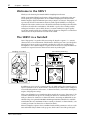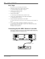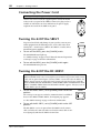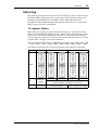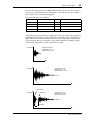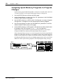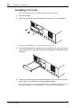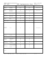
1
SAMPLING REVERBERATOR
Owner’s Manual
POWER
INPUT
1
2
3
OUTPUT
4
CLIP
CH
SIGNAL
FS LOCK
48K
1
2
3
4
44.1K
ON
MEMORY CARD
OFF
CD-ROM
Keep This Manual For Future Reference.
E
FCC INFORMATION (U.S.A.)
1. IMPORTANT NOTICE: DO NOT MODIFY THIS UNIT! This product, when installed as indicated in the instructions contained in this manual, meets FCC
requirements. Modifications not expressly approved by Yamaha may void your authority, granted by the FCC, to use the product.
2. IMPORTANT: When connecting this product to accessories and/or another product use only high quality shielded cables. Cable/s supplied with this product MUST
be used. Follow all installation instructions. Failure to follow instructions could void your FCC authorization to use this product in the USA.
3. NOTE: This product has been tested and found to comply with the requirements listed in FCC Regulations, Part 15 for Class “B” digital devices. Compliance with
these requirements provides a reasonable level of assurance that your use of this product in a residential environment will not result in harmful interference with
other electronic devices. This equipment generates/uses radio frequencies and, if not installed and used according to the instructions found in the users manual, may
cause interference harmful to the operation of other electronic devices. Compliance with FCC regulations does not guarantee that interference will not occur in all
installations. If this product is found to be the source of interference, which can be determined by turning the unit “OFF” and “ON”, please try to eliminate the
problem by using one of the following measures: Relocate either this product or the device that is being affected by the interference. Utilize power outlets that are on
different branch (circuit breaker or fuse) circuits or install AC line filter/s. In the case of radio or TV interference, relocate/reorient the antenna. If the antenna lead-in
is 300 ohm ribbon lead, change the lead-in to coaxial type cable. If these corrective measures do not produce satisfactory results, please contact the local retailer
authorized to distribute this type of product. If you can not locate the appropriate retailer, please contact Yamaha Corporation of America, Electronic Service
Division, 6600 Orangethorpe Ave, Buena Park, CA 90620
The above statements apply ONLY to those products distributed by Yamaha Corporation of America or its subsidiaries.
WARNING: THIS APPARATUS MUST BE EARTHED
IMPORTANT
THE WIRES IN THIS MAINS LEAD ARE COLOURED IN
ACCORDANCE WITH THE FOLLOWING CODE:
GREEN-AND-YELLOW :
EARTH
BLUE :
NEUTRAL
BROWN :
LIVE
As the colours of the wires in the mains lead of this apparatus may
not correspond with the coloured markings identifying the terminals in
your plug, proceed as follows:
The wire which is coloured GREEN and YELLOW must be
connected to the terminal in the plug which is marked by the letter E
or by the safety earth symbol
or coloured GREEN and YELLOW.
The wire which is coloured BLUE must be connected to the terminal
which is marked with the letter N or coloured BLACK.
The wire which is coloured BROWN must be connected to the
terminal which is marked with the letter L or coloured RED.
* This applies only to products distributed by YAMAHA KEMBLE
MUSIC (U.K.) LTD.
ADVARSEL!
Lithiumbatteri—Eksplosionsfare ved fejlagtig
håndtering. Udskiftning må kun ske med batteri
af samme fabrikat og type. Levér det brugte
batteri tilbage til leverandoren.
VARNING
Explosionsfara vid felaktigt batteribyte. Använd
samma batterityp eller en ekvivalent typ som
rekommenderas av apparattillverkaren.
Kassera använt batteri enligt fabrikantens
instruktion.
VAROITUS
Paristo voi räjähtää, jos se on virheellisesti
asennettu. Vaihda paristo ainoastaan
laitevalmistajan suosittelemaan tyyppiin. Hävitä
käytetty paristo valmistajan ohjeiden
mukaisesti.
Laser Diode Properties
* Material : GaAlAs
* Wavelength : 765–815nm
* Emission Duration : Continuous
* Laser Output Power : Less than 0.22mW
(Note) Laser output is measured at a
distance of 20cm from the object
lens on the optical pick-up head.
CLASS 1 LASER PRODUCT
LASER KLASSE 1 PRODUKT
LUOKAN 1 LASERLAITE
KLASS 1 LASERAPPARAT
This unit is classified as a
Class 1 laser product.
This label is located on the
rear panel.
Klassmärkning för Finland.
CAUTION
USE OF CONTROLS OR ADJUSTMENTS OR
PERFORMANCE OF PROCEDURES OTHER
THAN THOSE SPECIFIED HEREIN MAY RESULT
IN HAZARDOUS RADIATION EXPOSURE.
ATTENTION
TOUTE MANIPULATION DES COMMANDES,
TOUT RÉGLAGE OU TOUTE UTILISATION
AUTRES QUE CEUX SPÉCIFIÉS DANS CE
MANUEL POURRAIENT ENTRAÎNER UNE
EXPOSITION DANGEREUSE AUX RADIATIONS.
VORSICHT
DIE VERWENDUNG DER BEDIENELEMENTE
UND EINSTELLFUNKTIONEN BZW. DAS
AUSFÜHREN VON HANDLUNGEN IN EINER
NICHT AUSDRÜCKLICH IN DIESER
ANLEITUNG ERWAHNTEN WEISE KÖNNEN ZU
EINER GESUNDHEITSSCHADLICHEN
BESTRAHLUNG FÜHREN.
PRECAUCIÓN
EL USO DE CONTROLES, AJUSTES O LA
APLICACIÓN DE PROCEDIMIENTOS
DISTINTOS A LOS DESCRITOS EN ESTE
MANUAL, PUEDE OCASIONAR UNA
EXPOSICIÓN A RADIACIÓN PELIGROSA.
Important Information
i
Important Information
Read the following before using the SREV1
Warnings
• Do not subject the unit to extreme temperatures, humidity, direct sunlight, or dust,
which could be a potential fire or electrical shock hazard.
• Do not allow water to enter the unit or allow it to get wet. Fire or electrical shock may
result.
• Connect the power cord or AC adapter only to an AC outlet of the type stated in this
Owner’s Manual or as marked on the unit. Failure to do so is a fire and electrical shock
hazard.
• Hold the power-cord plug or AC adapter when disconnecting from an AC outlet. Never
pull the cord. A power cord damaged through pulling is a potential fire and electrical
shock hazard.
• Do not touch the power plug or AC adapter with wet hands. Doing so is a potential electrical shock hazard.
• Do not place heavy objects, including the unit, on top of the power cord. A damaged
power cord is a fire and electrical shock hazard. In particular, be careful not to place
heavy objects on a power cord covered by a carpet.
• Do not place a container with liquid or small metal objects on top of this unit. Liquid
or metal objects inside this unit are a fire and electrical shock hazard.
• Do not scratch, bend, twist, pull, or heat the power cord. A damaged power cord is a
fire and electrical shock hazard.
• If the power cord is damaged (e.g., cut or a bare wire is exposed), ask your dealer for a
replacement. Using the unit with a damaged power cord is a fire and electrical shock
hazard.
• Do not plug several pieces of equipment into the same AC outlet. This may overload
the AC outlet, and could be a fire or electrical shock hazard. It may also affect the performance of some equipment.
• If you notice any abnormality, such as smoke, odor, or noise, or if a foreign object or
liquid gets inside the unit, turn it off immediately. Remove the power cord or AC
adapter from the AC outlet and consult your dealer for repair. Using a unit in this condition is a fire and electrical shock hazard.
• Do not place small objects on top of the unit. Metal objects falling inside is a fire and
electrical shock hazard.
• If a foreign object or water gets inside the unit, turn it off immediately. Remove the
power cord or AC adapter from the AC outlet and consult your dealer for repair. Using
a unit in this condition is a potential fire and electrical shock hazard.
• If the unit is dropped or the cabinet damaged, turn off the power, remove the power
plug or AC adapter from the AC outlet, and contact your dealer. If you continue using
the unit without heeding this instruction, fire or electrical shock may result.
• Do not remove the unit covers. You could receive an electrical shock. If you think internal inspection, maintenance, or repair is necessary, contact your dealer.
• Do not attempt to modify the unit. This is a potential fire and electrical shock hazard.
SREV1—Owner’s Manual
ii
Important Information
• Do not block the front panel air inlet, ventilation slots, or fan outlets. Doing so is a
potential fire hazard.
Cautions
• Allow enough free space around the SREV1 for normal ventilation. This should be 20
cm behind, 10 cm at the sides, and 30 cm above. These distances should also be adopted
when rack-mounting the SREV1. If the SREV1 is mounted in a portable rack case, keep
the rear of the case open when using the SREV1 so as not to obstruct the flow of air from
the two cooling fans. If the airflow is not adequate, the SREV1 will heat up inside and
may cause a fire. Do not mount the SREV1 above equipment that produces a lot of heat,
such as a power amplifier.
• Turn off all audio equipment when connecting to the unit, and use only cables of the
type specified in this Owner’s Manual.
• If you plan not to use the unit for a long period of time, remove the power cord or AC
adapter from the AC outlet. Leaving the unit connected is a potential fire hazard.
• Do not use benzene, thinner, cleaning detergent, or a chemical cloth to clean the unit.
Use only a soft, dry cloth.
• If the unit is stored in a cold place (e.g., overnight in a car), and then moved to a warmer
environment, or if the temperature rises sharply, condensation may form inside the
unit, which may affect performance. In this case, the unit should be allowed to acclimatize for about one hour before use.
• When the wordclock is changed on the wordclock master device, noise may occur from
the SREV1’s outputs, especially if an MY8-AT I/O card is installed, so turn down your
power amps beforehand, otherwise any connected speakers may be damaged.
• If the RC-SREV1 displays the message “LOW BATTERY” when you turn on the unit,
ask your Yamaha dealer to replace the internal battery as soon as possible. The unit will
still work, but data other than backed up data will be lost. We recommend that you save
this data to a PC Card before replacing the battery.
• For electrical safety reasons, it’s important that the SREV1 is grounded properly. The
supplied power cord has a three-pin plug, and if the ground terminal of the AC outlet
is grounded, then the SREV1 will be grounded sufficiently through the power cord. If
the AC outlet does not provide a suitable ground, however, a ground connection should
be made to the dedicated grounding screw.
SREV1—Owner’s Manual
Important Information
iii
Handling CD-ROMs
• Use only discs of the type specified in this Owner’s Manual.
• The CD-ROM drive is for use with data discs only. Never insert audio CDs.
• Store discs in a place free from extreme temperatures, humidity, dust, and dirt.
• Always store discs in their cases.
• When handling discs, be careful not to touch the surface. Hold discs by the edge. Fingerprints, smudges, scratches, or dirt can affect performance.
• Be careful not to scratch the labeled side of the disc. Even scratches on that side can
affect performance.
• Fingerprints and dust should be removed by wiping gently from the center of the disc
towards the disc edge, using a soft, dry cloth. Never wipe in a circular motion and never
rub a disc hard with a dry cloth.
• For stubborn stains and dirt, use a cleaning kit designed specifically for use with CDs.
Do not use benzene, thinner, cleaning detergent, or a chemical cloth.
• For disc marking, use only pens specifically designed for writing on CDs and write only
on the designated area. Do not attach a label to a disc.
• If a disc is stored in a cold place (e.g., overnight in a car), and then moved to a warmer
environment, or if the temperature rises sharply, condensation may form on the disc
surface, which may affect performance. In this case, the disc should be allowed to acclimatize for about one hour before use.
• Do not under any circumstances attempt to use discs that are cracked or warped. Doing
so may seriously damage the unit.
Handling PC Cards
• Use only PC Cards of the type specified in this Owner’s Manual.
• Some PC Cards and PC Card adapters cannot be used with the SREV1.
• Do not eject a PC Card while the activity indicator is lit. Doing so may cause data lose.
• Store PC Cards in a place free from extreme temperatures, humidity, dust, and dirt.
• Always store PC Cards in their cases.
Precautions for Transportation
During transportation, keep the CD-ROM door shut with tape, or a pad, or the like.
• When using tape, use tape that adheres well to the front panel.
• When using a pad, use a pad stiff enough that the elasticity holds the tray in place.
Front panel
Pad
Tape
CD-ROM door
SREV1—Owner’s Manual
iv
Important Information
Interference
The SREV1 uses high-frequency digital circuits that may cause interference on radio
and television equipment located nearby. If interference is a problem, relocate the
affected equipment.
SREV1 Exclusion of Certain Responsibility
Manufacturer, importer, or dealer shall not be liable for any incidental damages including personal injury or any other damages caused by improper use or operation of the
SREV1.
Package Contents
The SREV1 package contains the following items:
• SREV1 Sampling Reverberator
• CD-ROM containing preset reverb programs and SREV1 utilities
• Power cord
• This Owner’s Manual
Contact your Yamaha dealer if something is missing.
Optional Extras
• RC-SREV1 Remote Controller
• DB-SREV1 DSP Expansion Board
Trademarks
ADAT MultiChannel Optical Digital Interface is a trademark and ADAT and Alesis are
registered trademarks of Alesis Corporation. Intel and Pentium are registered trademarks and MMX is a trademark of Intel Corporation. PCMCIA is a registered trademark of the Personal Computer Memory Card International Association. Tascam
Digital Interface is a trademark and Tascam and Teac are registered trademarks of Teac
Corporation. Windows is a trademark of Microsoft Corporation. Yamaha is a trademark of Yamaha Corporation. All other trademarks are the property of their respective
holders and are hereby acknowledged.
Copyright
No part of the SREV1, its software, including the supplied impulse-response data, or
this Owner’s Manual may be reproduced or distributed in any form or by any means
without the prior written authorization of Yamaha Corporation. Using the supplied
impulse-response data with equipment other than the SREV1, or obtaining the data by
sampling or any other means, is strictly prohibited.
© 2000 Yamaha Corporation. All rights reserved.
Yamaha Web Site
Information about the SREV1, related products, and other Yamaha professional audio
equipment is available on the Yamaha Professional Audio Web site at:
<http://www.yamaha.co.jp/product/proaudio/homeenglish/>.
SREV1—Owner’s Manual
Important Information
v
About this Manual
This Owner’s Manual covers both the SREV1 Sampling Reverberator and the optional
RC-SREV1 Remote Controller. (The SREV1 software manuals are on the CD-ROM.)
All the information you need in order to operate the SREV1 Sampling Reverberator
and the optional RC-SREV1 Remote Controller is contained in this manual. Use the
table of contents to familiarize yourself with its organization and locate topics, and use
the index to locate specific information. A glossary of SREV1-related jargon is provided
on page 93.
Installing the SREV1
When mounting the SREV1 in a rack, remove its feet and leave adequate ventilation
space all around (at least 20 cm of free space behind). If the SREV1 is mounted in a portable rack case, keep the rear of the case open when using the SREV1 so as not to
obstruct the flow of air from the two cooling fans. Do not mount the SREV1 above
equipment that produces a lot of heat, such as a power amplifier.
Conventions Used in this Manual
In this manual, the SREV1 Sampling Reverberator, the optional RC-SREV1 Remote
Controller, and the SREV1 software are referred to as the “SREV1,” “RC-SREV1,” and
“SREV1 software” respectively.
The RC-SREV1 features two types of button: physical buttons that you can press (e.g.,
ENTER and UTILITY) and buttons that appear on the RC-SREV1 display pages. References to physical buttons are enclosed in square brackets, such as “press the [ENTER]
button.” References to page buttons are not emphasized, for example, select the WCLK
IN button.
Generally there are three versions of each RC-SREV1 display page, one for each mode:
2-channel, 4-channel, and 2-channel x2. If relevant to the task being explained, all three
pages are shown. If the item being discussed is the same regardless of which mode is
selected, then only one page is shown.
“PC” refers to an IBM PC-compatible computer running a Windows operating system.
SREV1—Owner’s Manual
vi
Important Information
NEDERLAND
THE NETHERLANDS
● Dit apparaat bevat een lithium batterij voor geheugen
back-up.
● This apparatus contains a lithium battery for memory
back-up.
● Raadpleeg uw leverancier over de verwijdering van de
batterij op het moment dat u het apparaat ann het einde
van de levensduur afdankt of de volgende Yamaha Service
Afdeiing:
Yamaha Music Nederland Service Afdeiing
Kanaalweg 18-G, 3526 KL UTRECHT
Tel. 030-2828425
● For the removal of the battery at the moment of the
disposal at the end of the service life please consult your
retailer or Yamaha Service Center as follows:
Yamaha Music Nederland Service Center
Address: Kanaalweg 18-G, 3526 KL
UTRECHT
Tel: 030-2828425
● Gooi de batterij niet weg, maar lever hem in als KCA.
● Do not throw away the battery. Instead, hand it in as small
chemical waste.
SREV1—Owner’s Manual
vii
Contents
Contents
1
Welcome . . . . . . . . . . . . . . . . . . . . . . . . . . . . . . . . . 1
Welcome to the SREV1 . . . . . . . . . . . . . . . . . . . . . . . . . . . . . . . . . . . . . . . . . . . . 2
The SREV1 in a Nutshell . . . . . . . . . . . . . . . . . . . . . . . . . . . . . . . . . . . . . . . . . . . 2
SREV1 Features . . . . . . . . . . . . . . . . . . . . . . . . . . . . . . . . . . . . . . . . . . . . . . . . . . . 4
SREV1 Basics . . . . . . . . . . . . . . . . . . . . . . . . . . . . . . . . . . . . . . . . . . . . . . . . . . . . . 6
SREV1 Block Diagram . . . . . . . . . . . . . . . . . . . . . . . . . . . . . . . . . . . . . . . . . . . . 10
2
Touring the SREV1 & RC-SREV1 . . . . . . . . . . . . . . 11
SREV1 Front Panel . . . . . . . . . . . . . . . . . . . . . . . . . . . . . . . . . . . . . . . . . . . . . . .
SREV1 Rear Panel . . . . . . . . . . . . . . . . . . . . . . . . . . . . . . . . . . . . . . . . . . . . . . . .
RC-SREV1 Control Surface . . . . . . . . . . . . . . . . . . . . . . . . . . . . . . . . . . . . . . . .
RC-SREV1 Display . . . . . . . . . . . . . . . . . . . . . . . . . . . . . . . . . . . . . . . . . . . . . . .
RC-SREV1 Rear Panel . . . . . . . . . . . . . . . . . . . . . . . . . . . . . . . . . . . . . . . . . . . .
3
Getting Started . . . . . . . . . . . . . . . . . . . . . . . . . . . 21
First Steps . . . . . . . . . . . . . . . . . . . . . . . . . . . . . . . . . . . . . . . . . . . . . . . . . . . . . .
Connecting the RC-SREV1 Remote Controller . . . . . . . . . . . . . . . . . . . . . . . .
Hookup Examples . . . . . . . . . . . . . . . . . . . . . . . . . . . . . . . . . . . . . . . . . . . . . . .
Connecting the Power Cord . . . . . . . . . . . . . . . . . . . . . . . . . . . . . . . . . . . . . . .
Turning On & Off the SREV1 . . . . . . . . . . . . . . . . . . . . . . . . . . . . . . . . . . . . . .
Turning On & Off the RC-SREV1 . . . . . . . . . . . . . . . . . . . . . . . . . . . . . . . . . .
Using an Optional RC-SREV1 AC Adapter . . . . . . . . . . . . . . . . . . . . . . . . . . .
Adjusting the RC-SREV1 Brightness & Contrast . . . . . . . . . . . . . . . . . . . . . .
Using CD-ROMs . . . . . . . . . . . . . . . . . . . . . . . . . . . . . . . . . . . . . . . . . . . . . . . .
Using PC Cards . . . . . . . . . . . . . . . . . . . . . . . . . . . . . . . . . . . . . . . . . . . . . . . . . .
4
22
22
23
26
26
26
27
27
28
29
Basic Operation . . . . . . . . . . . . . . . . . . . . . . . . . . . 31
SREV1 Startup . . . . . . . . . . . . . . . . . . . . . . . . . . . . . . . . . . . . . . . . . . . . . . . . . .
RC-SREV1 Startup . . . . . . . . . . . . . . . . . . . . . . . . . . . . . . . . . . . . . . . . . . . . . . .
About the Internal Operations at Startup . . . . . . . . . . . . . . . . . . . . . . . . . . . .
Selecting Reverb Modes . . . . . . . . . . . . . . . . . . . . . . . . . . . . . . . . . . . . . . . . . . .
Assigning Inputs . . . . . . . . . . . . . . . . . . . . . . . . . . . . . . . . . . . . . . . . . . . . . . . . .
Setting Input & Output Levels . . . . . . . . . . . . . . . . . . . . . . . . . . . . . . . . . . . . .
Metering . . . . . . . . . . . . . . . . . . . . . . . . . . . . . . . . . . . . . . . . . . . . . . . . . . . . . . .
Setting the Meter Mode . . . . . . . . . . . . . . . . . . . . . . . . . . . . . . . . . . . . . . . . . . .
Using Peak Hold . . . . . . . . . . . . . . . . . . . . . . . . . . . . . . . . . . . . . . . . . . . . . . . . .
Bypassing the SREV1 . . . . . . . . . . . . . . . . . . . . . . . . . . . . . . . . . . . . . . . . . . . . .
Setting the Bypass Mode . . . . . . . . . . . . . . . . . . . . . . . . . . . . . . . . . . . . . . . . . .
Using the Title Edit dialog Box . . . . . . . . . . . . . . . . . . . . . . . . . . . . . . . . . . . . .
Working with Quick Memories . . . . . . . . . . . . . . . . . . . . . . . . . . . . . . . . . . . .
Working with the Library . . . . . . . . . . . . . . . . . . . . . . . . . . . . . . . . . . . . . . . . .
Working with Projects . . . . . . . . . . . . . . . . . . . . . . . . . . . . . . . . . . . . . . . . . . . .
5
12
14
16
18
20
32
32
33
34
35
36
37
39
39
40
40
41
42
45
48
Editing Programs . . . . . . . . . . . . . . . . . . . . . . . . . . 51
Main 1 Parameters . . . . . . . . . . . . . . . . . . . . . . . . . . . . . . . . . . . . . . . . . . . . . . .
Main 2 Parameters . . . . . . . . . . . . . . . . . . . . . . . . . . . . . . . . . . . . . . . . . . . . . . .
Fine Reverb Parameters . . . . . . . . . . . . . . . . . . . . . . . . . . . . . . . . . . . . . . . . . . .
Pre EQ . . . . . . . . . . . . . . . . . . . . . . . . . . . . . . . . . . . . . . . . . . . . . . . . . . . . . . . . .
Post EQ . . . . . . . . . . . . . . . . . . . . . . . . . . . . . . . . . . . . . . . . . . . . . . . . . . . . . . . .
Loading Impulse-Response Data . . . . . . . . . . . . . . . . . . . . . . . . . . . . . . . . . . .
52
54
56
57
59
61
SREV1—Owner’s Manual
viii
Contents
6
Multiple SREV1s . . . . . . . . . . . . . . . . . . . . . . . . . . . 63
About Multiple SREV1s . . . . . . . . . . . . . . . . . . . . . . . . . . . . . . . . . . . . . . . . . . .
Connections . . . . . . . . . . . . . . . . . . . . . . . . . . . . . . . . . . . . . . . . . . . . . . . . . . . . .
Multiple-unit Hookup with the RC-SREV1 . . . . . . . . . . . . . . . . . . . . . . . . . . .
Multiple-unit Operating Notes . . . . . . . . . . . . . . . . . . . . . . . . . . . . . . . . . . . . .
Selecting SREV1s from the RC-SREV1 . . . . . . . . . . . . . . . . . . . . . . . . . . . . . . .
7
MIDI . . . . . . . . . . . . . . . . . . . . . . . . . . . . . . . . . . . . 67
MIDI & the SREV1 . . . . . . . . . . . . . . . . . . . . . . . . . . . . . . . . . . . . . . . . . . . . . . .
MIDI Ports . . . . . . . . . . . . . . . . . . . . . . . . . . . . . . . . . . . . . . . . . . . . . . . . . . . . . .
MIDI Pages . . . . . . . . . . . . . . . . . . . . . . . . . . . . . . . . . . . . . . . . . . . . . . . . . . . . . .
Setting the MIDI Receive Channels . . . . . . . . . . . . . . . . . . . . . . . . . . . . . . . . . .
Assigning Quick Memory Programs to Program Changes . . . . . . . . . . . . . . .
Assigning Parameters to Control Changes . . . . . . . . . . . . . . . . . . . . . . . . . . . .
8
68
68
69
69
70
71
Wordclocks . . . . . . . . . . . . . . . . . . . . . . . . . . . . . . . 73
Wordclocks & the SREV1 . . . . . . . . . . . . . . . . . . . . . . . . . . . . . . . . . . . . . . . . . .
Wordclock Connections . . . . . . . . . . . . . . . . . . . . . . . . . . . . . . . . . . . . . . . . . . .
Selecting the Wordclock Source . . . . . . . . . . . . . . . . . . . . . . . . . . . . . . . . . . . . .
Wordclock Hookup Examples . . . . . . . . . . . . . . . . . . . . . . . . . . . . . . . . . . . . . .
9
64
64
64
65
65
74
74
75
78
I/O Options . . . . . . . . . . . . . . . . . . . . . . . . . . . . . . . 81
I/O Options & the SREV1 . . . . . . . . . . . . . . . . . . . . . . . . . . . . . . . . . . . . . . . . . .
Available I/O Cards . . . . . . . . . . . . . . . . . . . . . . . . . . . . . . . . . . . . . . . . . . . . . . .
Choosing I/O Cards . . . . . . . . . . . . . . . . . . . . . . . . . . . . . . . . . . . . . . . . . . . . . .
Installing I/O Cards . . . . . . . . . . . . . . . . . . . . . . . . . . . . . . . . . . . . . . . . . . . . . . .
82
82
83
84
Troubleshooting . . . . . . . . . . . . . . . . . . . . . . . . . . . . . . 85
Appendix . . . . . . . . . . . . . . . . . . . . . . . . . . . . . . . . . . . 87
Error Messages . . . . . . . . . . . . . . . . . . . . . . . . . . . . . . . . . . . . . . . . . . . . . . . . . . .
Confirmation Messages . . . . . . . . . . . . . . . . . . . . . . . . . . . . . . . . . . . . . . . . . . .
General Messages . . . . . . . . . . . . . . . . . . . . . . . . . . . . . . . . . . . . . . . . . . . . . . . . .
General Specifications . . . . . . . . . . . . . . . . . . . . . . . . . . . . . . . . . . . . . . . . . . . . .
Digital Input Specifications . . . . . . . . . . . . . . . . . . . . . . . . . . . . . . . . . . . . . . . .
Digital Output Specifications . . . . . . . . . . . . . . . . . . . . . . . . . . . . . . . . . . . . . . .
Control I/O Specifications . . . . . . . . . . . . . . . . . . . . . . . . . . . . . . . . . . . . . . . . .
Remote Cable Wiring Diagram . . . . . . . . . . . . . . . . . . . . . . . . . . . . . . . . . . . . .
Dimensions . . . . . . . . . . . . . . . . . . . . . . . . . . . . . . . . . . . . . . . . . . . . . . . . . . . . .
87
88
89
90
91
91
91
91
92
Glossary . . . . . . . . . . . . . . . . . . . . . . . . . . . . . . . . . . . . 93
Index . . . . . . . . . . . . . . . . . . . . . . . . . . . . . . . . . . . . . . . 95
MIDI Implementation Chart
SREV1—Owner’s Manual
Welcome
1
Welcome
1
In this chapter...
Welcome to the SREV1 . . . . . . . . . . . . . . . . . . . . . . . . . . . . . . . . . . . . . . . . . . . . . 2
The SREV1 in a Nutshell . . . . . . . . . . . . . . . . . . . . . . . . . . . . . . . . . . . . . . . . . . . . 2
SREV1 Features . . . . . . . . . . . . . . . . . . . . . . . . . . . . . . . . . . . . . . . . . . . . . . . . . . . . 4
SREV1 Basics . . . . . . . . . . . . . . . . . . . . . . . . . . . . . . . . . . . . . . . . . . . . . . . . . . . . . . 6
SREV1 Block Diagram . . . . . . . . . . . . . . . . . . . . . . . . . . . . . . . . . . . . . . . . . . . . . 10
SREV1—Owner’s Manual
2
Chapter 1—Welcome
Welcome to the SREV1
Thank you for choosing the Yamaha SREV1 Sampling Reverberator.
Unlike conventional digital reverberators, which synthesize reverberation using contrived signal-processing algorithms, the new SREV1 Sampling Reverberator from
Yamaha employs digital convolution processing to impose an acoustic “fingerprint” of
a previously measured environment onto any audio signal, faithfully recreating the
original reverberation, with accurate reflection detail identical to that produced had the
sound been heard in that environment. The SREV1 is perfect for recording studios,
audio post, broadcast, concert halls, theaters, or anyone looking for superb quality
reverb that sounds just like the real thing, with the option to sample the reverberation
characteristics of any location for use back in the studio.
The SREV1 in a Nutshell
Sonic “fingerprints” are produced by measuring the impulse response (i.e., acoustic
characteristics) of an environment, which involves “blasting out” time-stretched pulses
through an accurate speaker system and recording the results via carefully placed
microphones. The resultant impulse-response data can then be used by the SREV1 to
convolve the captured acoustic characteristics onto any audio signal.
Sampling on location
Convolution processing
POWER
Firing time-stretched pulses
INPUT
1
2
3
OUTPUT
4
CLIP
CH
SIGNAL
FS LOCK
48K
1
2
3
4
44.1K
ON
L
20
POWER
TEMP
PROTECTION
POWER
ON
OFF
CD-ROM
MEMORY CARD
CLIP
R
L
15
20
25
LEVEL
6
3
40
L
0
15
20
25
10
30
OFF
10
30
6
3
40
–dB
R
0
CLIP
R
15
20
25
LEVEL
6
3
40
L
0
15
25
10
30
10
30
6
3
40
–dB
R
0
Impulse-response data
PC ATA CARD
FL
FR
RL
RR
FLASH CARD
POWER
INPUT
1
2
3
OUTPUT
4
CLIP
CH
SIGNAL
FS LOCK
48K
1
2
3
4
44.1K
ON
MEMORY CARD
OFF
CD-ROM
In addition to stereo reverb (2-channel mode), the SREV1 offers four-channel processing for surround reverb (4-channel mode). Alternatively, the SREV1 can be configured
as two fully independent reverberators (2-channel x2 mode), each with its own inputs,
outputs, and program settings.
Thirty-two of Yamaha’s new convolution chips provide the necessary “horsepower” for
real-time convolution of up to 5.46 seconds per channel (2-channel mode), 2.73 seconds per channel (4-channel or 2-channel x2 mode). Featuring an additional 32 convolution chips, the optional DB-SREV1 DSP Expansion Board doubles the available
convolution time to a maximum of 10.92 seconds per channel (2-channel mode), 5.46
seconds per channel (4-channel or 2-channel x2 mode).
Measured impulse response data is combined with variable parameters such as reverb
time and initial delay to form reverb programs, which can be stored in special Quick
SREV1—Owner’s Manual
The SREV1 in a Nutshell
3
memories or the Internal Card or PC Card. Up to six programs can be stored in Quick
memory in 2-channel or 4-channel mode; 12 in 2-channel x2 mode. Programs in
Quick memory can be recalled instantly via the optional RC-SREV1 Remote Controller
or MIDI Program Changes.
Projects, which contain all the Quick memory programs and the current program settings, provide a convenient way to manage programs and settings for each job. Projects
can be stored on the Internal Card or PC Card.
The PC Card slot is fully compatible with the PC Card ATA specification and supports
the FAT16 file system. The CD-ROM drive supports the ISO9660 Level 2 format. Both
the PC Card and CD-ROM format is compatible with Windows.
The supplied CD-ROM contains preset reverb programs of famous venues from
around the world, and a CD-ROM library is planned for future release. The preset programs on the supplied CD-ROM are loaded into the Internal Card at the factory.
Program editing is handled at two levels: Main parameters and Fine parameters. With
Main parameter editing, channel parameters, such as reverb time, initial delay, reverb
balance, EQ, etc., are grouped, so that, for example, the reverb time of all channels can
be set simultaneously. Fine parameter editing adds pre-convolution 4-band PEQ,
post-convolution 4-band PEQ, and impulse-response data loading. Reverb parameters
can be edited individually or grouped. Reverb balance and reverb level parameters for
each channel can be controlled individually via MIDI Control Changes.
Two AES/EBU inputs and outputs (providing 4 channels) are built in and two mini
YGDAI (Yamaha General Digital Audio Interface) slots offer various analog and digital
I/O options (AES/EBU, ADAT, Tascam). Inputs can be assigned to channels individually, allowing various input/output configurations. In 2-channel mode, for example, a
single input can be assigned to both channels (left and right) for mono in/stereo out
operation, or an individual input can be assigned to each channel for true stereo in/stereo out operation.
Superb sonic performance is provided by Yamaha’s new convolution chip, 24-bit I/O,
32-bit internal signal processing, and 48 kHz internal wordclock. External wordclocks
of 44.1 kHz and 48 kHz are supported and can be sourced via the dedicated BNC wordclock input, AES/EBU inputs, or card slot inputs.
Up to four SREV1s can be controlled using the optional RC-SREV1 Remote Controller,
which features a large 320 x 240 dot graphical display, with fluorescent backlight and
adjustable brightness and contrast, four motorized faders for parameter editing, and
input and output clip indicators. Power is supplied by the SREV1.
SREV1—Owner’s Manual
4
Chapter 1—Welcome
SREV1 Features
Sonic Performance
• 32 Yamaha convolution chips
• 24-bit I/O and 32-bit internal processing
• 48 kHz internal wordclock
• 44.1 kHz or 48 kHz external wordclock
Reverb Modes & Convolution Times
• 2-channel (stereo), 4-channel (surround), and 2-channel x2 (A and B) reverb modes
• Maximum convolution time of 5.46 seconds per channel (2-channel mode), 2.73 seconds per channel (4-channel mode or 2-channel x2 mode)
• Featuring an additional 32 convolution chips, the optional DB-SREV1 DSP Expansion
Board doubles the available convolution time to a maximum of 10.92 seconds per
channel (2-channel mode), 5.46 seconds per channel (4-channel or 2-channel x2
mode)
Programs & Projects
• Programs combine impulse-response data with variable parameters such as reverb
time, initial delay, EQ, and more
• Quick memories hold six instantly recallable programs (2-channel or 4-channel
mode); 12 programs (2-channel x2 mode)
• Quick memory programs can be recalled via MIDI
• Projects provide a convenient way to manage programs for each job
• Programs and projects can be saved on the Internal Card or PC Card
Storage
• PC Card slot fully compatible with the PC Card ATA specification and supports the
FAT16 file system
• CD-ROM drive supports ISO9660 Level 2 format
• PC Card and CD-ROM formats compatible with Windows
Editing
• Basic editing includes reverb time, initial delay, and reverb balance
• Advanced editing includes basic parameters plus pre-convolution 4-band PEQ,
post-convolution 4-band PEQ, and impulse-response data loading for each channel
• Reverb balance and level parameters can be controlled via MIDI
SREV1—Owner’s Manual
SREV1 Features
5
Flexible I/O
• Two AES/EBU format inputs and outputs (providing 4 channels)
• Two mini YGDAI (Yamaha General Digital Audio Interface) slots
• Optional mini YGDAI cards offer a variety of analog and digital I/O configurations,
with support for all the popular digital audio interconnect formats, including
AES/EBU, ADAT, and Tascam
Optional RC-SREV1 Remote Controller
• Control up to four SREV1s
• Large 320 x 240 dot display, with fluorescent backlight and adjustable brightness and
contrast
• Four motorized faders, data wheel, and INC/DEC buttons for parameter editing
• Input and output signal clip indicators
• Power supplied by the SREV1 (DC IN connector for use with optional AC adapter and
custom remote cables)
Others
• Yamaha CD-ROM library of famous venues from around the world
• SERIAL ports for multiple-unit operation
• MIDI IN and OUT ports
• BNC wordclock input
• 3U rack space
SREV1—Owner’s Manual
6
Chapter 1—Welcome
SREV1 Basics
Reverb Modes
The SREV1 offers three Reverb modes: 2-channel, 4-channel, and 2-channel x2. In
2-channel mode, the SREV1 functions as a stereo reverb processor. Use this mode if all
you require is stereo outputs, as it offers the maximum convolution time per channel.
In 4-channel mode, the SREV1 offers 4-channel processing for surround reverb. In
2-channel x2 mode, the SREV1 functions as two independent stereo reverb processors
(A and B).
See page 34 for information on selecting Reverb modes.
The onboard AES/EBU inputs and mini YGDAI slot inputs can be freely assigned to
channels. See “Assigning Inputs” on page 35 for more information.
Convolution Times
The following table shows the maximum convolution time available per channel for
each mode with and without the optional DB-SREV1 DSP Expansion Board installed.
Maximum Convolution Time per Channel (Fs = 48 kHz)
Mode
Base System
with DSP Expansion Board
(DB-SREV1)
2-channel
5.46 sec
10.92 sec
4-channel
2.73 sec
5.46 sec
2-channel x2
2.73 sec
5.46 sec
Convolution time is not the same as reverb time. Reverb time is the time it takes the
reverb to decay to –60 dB, and more convolution is required to provide reverberation
to –90 dB or –120 dB, so the convolution time must be between 1.5 and 2 times more
than the reverb time.
Impulse-Response Data
Impulse-response data contains the impulse-response information (i.e., acoustic characteristics) of a measured environment. Preset programs come with their own
impulse-response data. Each channel of a program is assigned impulse-response data,
as shown below, and data can be loaded for channels individually on the Data Load
pages. See “Loading Impulse-Response Data” on page 61 for more information. The
impulse-response data for the preset programs is loaded into the Internal Card at the
factory. It’s also on the supplied CD-ROM.
2-channel mode
4-channel mode
Left
Front-left
A-left
Right
Front-right
A-right
Rear-left
B-left
Rear-right
B-right
2-channel program
4-channel program
SREV1—Owner’s Manual
2-channel x2 mode
2-channel program x2
SREV1 Basics
7
Programs
There are two types of reverb program: 2-channel and 4-channel. Two-channel programs are for use with 2-channel mode and 2-channel x2 mode, while 4-channel programs are for use only with 4-channel mode. In 2-channel mode, 4-channel programs
do not appear in the program lists and vice versa. The preset programs on the supplied
CD-ROM are loaded into the Internal Card at the factory. User programs can be stored
in the Quick memories, Internal Card or PC Card, where they can be write-protected.
Projects
Projects contain all the Quick memory programs and the current program settings and
free you to leave a project and come back to it at any time. Projects can be saved to the
Internal Card or PC Card, where they can be write-protected.
There are three types of project: 2-channel, 4-channel, and 2-channel x2. Each project
type is available only when the corresponding mode is selected. You can’t, for example,
select a 2-channel project in 4-channel mode. Projects are managed on the Project
pages. See “Working with Projects” on page 48 for more information.
Quick Memories
Quick memories are special memories for storing programs. Unlike programs on the
Internal Card, PC Cards, and CD-ROMs, which take time to load, Quick memory programs can be recalled instantly. There are six Quick memories available in 2-channel or
4-channel mode; 12 in 2-channel x2 mode. Quick memories are managed on the Program pages. See “Working with Quick Memories” on page 42 for more information.
SREV1—Owner’s Manual
8
Chapter 1—Welcome
Drives
Programs, projects, and impulse-response data can be loaded from the following
drives: Internal Card, PC Card, or CD-ROM. The number of programs that can be
stored on each drive depends on its capacity and the size of the associated
impulse-response data. Programs and drives are managed on the Library pages. See
“Working with the Library” on page 45 for more information.
The following diagram shows how programs and projects can be transferred to and
from the drives and Quick memories, and impulse-response data transferred from the
drives.
Drives
Internal Card
PC Card
CD-ROM
PC ATA CARD
FLASH CARD
Impulse-response
data
Project
P01
Current program
P02
P03
P04
P05
P06
Quick memories
See the Program pages for Quick memory store/recall operations
See the Library pages for program and drive save/load operations
See the Project pages for project and drive save/load operations
See the Data Load pages for impulse-response data loading
SREV1—Owner’s Manual
SREV1 Basics
9
File Types
The SREV1 uses several file extensions to identify file types. Although these extensions
do not generally appear on the RC-SREV1 pages, they may come in useful when checking the contents of a PC Card or CD-ROM on your PC.
File
Extension
File Type
TM4
Impulse-response data (Yamaha original format)
TMC
Compressed and encrypted impulse-response data (Yamaha original format)
SP2
2-channel program
SP4
4-channel program
2CH
2-channel mode project
4CH
4-channel mode project
2X2
2-channel x2 mode project
Parameters
SREV1 program parameters, such as reverb time, initial delay, an EQ, are stored within
each program. Saved parameters include: reverb time, initial delay, reverb balance,
reverb level, pre EQ, post EQ, and impulse-response data names.
Other parameters, including reverb mode, wordclock source, I/O select, I/O level, and
MIDI settings, are not stored within each program, but they are stored in the SREV1’s
battery-backed memory.
Output Assignments
The following table shows the fixed output assignments for each mode.
Outputs
Mode
Channel
AES1 AES2
1
2-channel
Left
4-channel
1
•
•
2-channel x2
B-left
B-right
•
•
•
•
Rear-right
A-right
•
•
•
Rear-left
SLOT2
•
•
Front-right
A-left
SLOT1
2 1 2 3 4 5 6 7 8 1 2 3 4 5 6 7 8
•
Right
Front-left
2
•
•
•
•
•
•
•
•
•
•
•
•
•
•
•
•
•
•
SREV1—Owner’s Manual
SREV1—Owner’s Manual
SLOT 2
SLOT 1
AES/EBU
IN 2
AES/EBU
IN 1
Input
Select
Initial
Delay
Pre EQ
Convolution
As above (Rear-right, B-right)
As above (Rear-left, B-left)
As above (Right, Front-right, A-right)
Input
Level
Input
Meter
(Left, Front-left, A-left)
Post EQ
Off
Bypass
(Rev Mute)
On
Reverb
Balance
Reverb
Level
Off
Bypass
(Direct Out)
On
Output
Level
Output
Meter
SLOT 2
SLOT 1
AES/EBU
OUT 2
AES/EBU
OUT 1
10
Chapter 1—Welcome
SREV1 Block Diagram
Touring the SREV1 & RC-SREV1
11
Touring the SREV1 & RC-SREV1
2
In this chapter...
SREV1 Front Panel . . . . . . . . . . . . . . . . . . . . . . . . . . . . . . . . . . . . . . . . . . . . . . . .
SREV1 Rear Panel . . . . . . . . . . . . . . . . . . . . . . . . . . . . . . . . . . . . . . . . . . . . . . . . .
RC-SREV1 Control Surface . . . . . . . . . . . . . . . . . . . . . . . . . . . . . . . . . . . . . . . . .
RC-SREV1 Display . . . . . . . . . . . . . . . . . . . . . . . . . . . . . . . . . . . . . . . . . . . . . . . .
RC-SREV1 Rear Panel . . . . . . . . . . . . . . . . . . . . . . . . . . . . . . . . . . . . . . . . . . . . .
12
14
16
18
20
SREV1—Owner’s Manual
12
Chapter 2—Touring the SREV1 & RC-SREV1
SREV1 Front Panel
1
2
3
4
POWER
INPUT
1
2
3
OUTPUT
4
CLIP
CH
SIGNAL
FS LOCK
48K
1
2
3
4
44.1K
ON
CD-ROM
MEMORY CARD
5
OFF
67
8
9 J K
A Air Inlet
The two internal cooling fans draw air into the SREV1 through this inlet. If the airflow
is restricted, the SREV1 may overheat, so make sure that it’s not blocked.
B INPUT and OUTPUT signal indicators
The INPUT and OUTPUT signal level indicators consist of SIGNAL and CLIP indicators for each channel. The SIGNAL indicators light up when a signal is 34 dB below
clipping and are intended to show the presence of a signal, while the CLIP indicators
light up when a signal is actually clipping. See “Metering” on page 37 for more information.
C FS LOCK indicators
These indicators show the sampling rate—48 kHz or 44.1 kHz—and whether or not
the SREV1 is locked to the selected wordclock source. See “Selecting the Wordclock
Source” on page 75 for more information.
D POWER switch & indicator
This switch is used to turn on the power to the SREV1. The POWER indicator lights up
when the SREV1 is turned on. See “Turning On & Off the SREV1” on page 26 for more
information.
E MEMORY CARD slot
PC Cards can be inserted here for loading and saving programs, projects, or
impulse-response data. See “Using PC Cards” on page 29 for more information.
F Memory card eject button
This button is used to eject PC Cards. See “Using PC Cards” on page 29 for more information.
G Memory card activity indicator
This indicator lights up when the inserted PC Card is being written or read. See “Using
PC Cards” on page 29 for more information.
SREV1—Owner’s Manual
SREV1 Front Panel
13
H CD-ROM drive
The supplied CD-ROM, containing reverb programs, projects, and impulse-response
data, can be inserted here. See “Using CD-ROMs” on page 28 for more information.
I Disc activity indicator
This indicator lights up when the inserted CD-ROM is being read. See “Using
CD-ROMs” on page 28 for more information.
J CD-ROM eject button
This button is used to eject CD-ROMs. See “Using CD-ROMs” on page 28 for more
information.
K Emergency disc eject hole
This hole is used to manually eject CD-ROMs that cannot be ejected in the normal way.
Use a pin-like tool of 2 mm or less in diameter, insert it into the hole and push gently.
(A straightened paper clip makes an ideal tool.) Note that this technique should only be
used as a last resort. Frequent use may lead to malfunction.
SREV1—Owner’s Manual
14
Chapter 2—Touring the SREV1 & RC-SREV1
SREV1 Rear Panel
1
2
1
SLOT
1
SLOT
2
OUT
2
1
2
MIDI
1
IN
2
SERIAL
1
REMOTE
WORD CLOCK IN
9
J
AC IN
1
3
2
1
3
2
2
1
2
3
OUT
3
4
DIGITAL (AES/EBU)
5
1
3
IN
6
7
8
A Cooling fan outlets
The two cooling fans expel air out through these outlets. If the airflow is restricted, the
SREV1 may overheat, so make sure these outlets are not blocked.
B SLOTs 1 & 2
These two slots are for use with optional mini YGDAI cards, offering a variety of analog
and digital I/O options. See “I/O Options” on page 81 for more information. Slot inputs
can be freely assigned to channels. See “Assigning Inputs” on page 35 for more information.
C AC IN connector
This connector is used to connect the SREV1 to a suitable AC outlet by using the supplied power cord. See “Connecting the Power Cord” on page 26 for more information.
D Grounding screw
For safety reasons, it’s important that the SREV1 is grounded properly. The supplied
power cord has a three-pin plug, and if the ground terminal of the AC outlet is
grounded, then the SREV1 will be grounded sufficiently through the power cord. If the
AC outlet does not provide a suitable ground, however, a ground connection should be
made to this grounding screw. Grounding is also an effective method for eliminating
hum, interference, and other noise.
E DIGITAL OUT (AES/EBU) connectors
These two XLR-3-32-type connectors (AES1 and AES2) transmit up to four output signals, two per connection, as AES/EBU format digital audio. Output to channel assignments are fixed. See “Output Assignments” on page 9 for more information. Use only
dedicated AES/EBU connecting cables (110Ω).
F DIGITAL IN (AES/EBU) connectors
These two XLR-3-31-type connectors (AES1 and AES2) receive up to four input signals, two per connection, as AES/EBU format digital audio. AES/EBU inputs can be
freely assigned to channels. See “Assigning Inputs” on page 35 for more information.
Use only dedicated AES/EBU connecting cables (110Ω).
SREV1—Owner’s Manual
SREV1 Rear Panel
15
G MIDI IN & OUT ports
These standard MIDI IN and OUT ports and are used to connect the SREV1 to other
MIDI equipment for remote operation using MIDI Program Change and Control
Change messages. See “MIDI & the SREV1” on page 68 for more information.
H SERIAL 1 & 2 ports
These 8-pin mini DIN connectors are used to connect up to four SREV1s in a multiple-unit system. See “Multiple SREV1s” on page 63 for more information.
I REMOTE port
This 9-pin D-sub connector is used to connect the RC-SREV1. See “Connecting the
RC-SREV1 Remote Controller” on page 22 for more information.
J WORD CLOCK IN connector
This BNC connector can be used to receive an external wordclock signal. See “Wordclock Connections” on page 74 for more information.
SREV1—Owner’s Manual
16
Chapter 2—Touring the SREV1 & RC-SREV1
RC-SREV1 Control Surface
INPUT CLIP
CH
1 2 3 4
OUTPUT CLIP
1
-1/DEC
BYPASS
2
8
9
+1/INC
PARAMETER
J
PROGRAM
3
K
PARAMETER
MAIN
4
PARAMETER
FINE
5
CURSOR
UTILITY
L
6
ENTER
M
7
A Display
See “RC-SREV1 Display” on page 18 for more information.
B BYPASS button & indicator
This button is used to bypass the SREV1. The BYPASS indicator lights up when the
SREV1 is bypassed. See “Bypassing the SREV1” on page 40 for more information.
C PROGRAM button
This button selects the Program, Library, and Project pages.
D PARAMETER MAIN button
This button selects the Main 1 and Main 2 pages.
E PARAMETER FINE button
This button selects the Rev, Pre EQ, and Post EQ pages.
F UTILITY button
This button selects the Setup, DIO, Meter I/O, and MIDI pages.
SREV1—Owner’s Manual
RC-SREV1 Control Surface
17
G Motorized faders
These four 60-mm motorized faders are for adjusting parameter values and input and
output levels.
H INPUT CLIP indicators
There are four INPUT CLIP indicators, one for each channel, which light up when the
corresponding channel’s input signal is clipping.
I OUTPUT CLIP indicators
There are four OUTPUT CLIP indicators, one for each channel, which light up when
the corresponding channel’s output signal is clipping.
J –1/DEC & +1/INC buttons
These buttons work in parallel with the DATA wheel and are used for selecting programs or projects and setting parameter values. Use the [–1/DEC] button to decrease a
value; the [+1/INC] button to increase it.
K DATA wheel
This wheel is used for selecting programs or projects and setting parameter values. Turn
it clockwise to increase a value; counterclockwise to decrease it.
L Cursor buttons (
/
/
/ )
These buttons are used to maneuver the cursor around the display pages in order to
select buttons and parameters. The left ( ) button moves the cursor to the left; the
right ( ) button moves it to the right; the up ( ) button moves it up; the down ( )
button moves it down.
M ENTER button
This button is used to execute functions and set options and parameters.
SREV1—Owner’s Manual
18
Chapter 2—Touring the SREV1 & RC-SREV1
RC-SREV1 Display
This large 320 x 240 dot display, with fluorescent backlight and adjustable brightness
and contrast controls, displays the various program, parameter, and utility pages, system status, and signal level meters. As well as showing parameter values numerically,
reverb and EQ parameters are displayed graphically, so you can see settings at a glance.
Bypass status
FS status
Page title
Program number & title
Selected SREV1
Reverb mode
Edit status
Page tabs
Main page area
Meters
Page title—This is the title of the currently selected page.
Program number & title—This is the number and title of the current program. In
2-channel x2 mode, two numbers and titles are displayed, one for program A, the other
for program B. Program numbers appear only when programs are recalled or stored in
Quick memory. They do not appear when programs are loaded from a drive (i.e., Internal Card, PC Card, or CD-ROM).
Page tabs—Pages are grouped as program, parameter main, parameter fine, and utility, and these tabs show the titles of the pages available in each group.
Main page area—The various program, parameter, and utility pages appear here.
Bypass status—The status of the Bypass function appears here: ON (SREV1
bypassed) or OFF. See “Bypassing the SREV1” on page 40 for more information.
FS status—The SREV1 sampling rate is displayed here—48 kHz or 44.1 kHz—and
whether or not it’s locked to the selected wordclock source—LOCK or UNLOCK. See
“Selecting the Wordclock Source” on page 75 for more information.
Selected SREV1—This is the SREV1 currently selected for control from the
RC-SREV1. See “Selecting SREV1s from the RC-SREV1” on page 65 for more information.
Reverb mode—This is the current Reverb mode: 2CH, 4CH, or 2CHX2.
Edit status—The Edit status indicator shows whether or not the current reverb program has been edited since is was recalled. If it has, the word “EDIT” appears (the letter
“E” appears in 2-channel x2 mode).
Meters—In 2-channel mode, input and output meters for the left and right channels
are displayed here. In 4-channel mode, meters for the front-left, front-right, rear-left,
and rear-right channels are displayed. In 2-channel x2 mode, meters for the A-left,
A-right, B-left, and B-right channels are displayed. For the 4-channel and 2-channel x2
modes, you can choose to display input or output meters. See “Metering” on page 37
for more information.
SREV1—Owner’s Manual
RC-SREV1 Display
19
Fader status—The status of each fader appears along the bottom of the display. For
pages selected with the [PARAMETER MAIN] button, the names of the parameters
assigned to the faders appear, and for pages selected with the [PARAMETER FINE]
button, the channel names appear, as shown below.
Parameter
Channel
SREV1—Owner’s Manual
20
Chapter 2—Touring the SREV1 & RC-SREV1
RC-SREV1 Rear Panel
POWER
ON
DC 12V IN
REMOTE
LCD
BRIGHT
CONT
5
6
OFF
1
2 3
4
A POWER switch
This switch is used to turn on the power to the RC-SREV1. Power is supplied by the
SREV1 via the remote cable, or an optional AC adapter. See “Turning On & Off the
RC-SREV1” on page 26 for more information.
B DC 12V IN connector
An optional AC adapter can be connected here (necessary when a custom-made remote
cable is used). See “Using an Optional RC-SREV1 AC Adapter” on page 27 for more
information.
C Adapter cable clip
This clip is used to secure the optional AC adapter’s cable in order to prevent accidental
disconnection. See “Using an Optional RC-SREV1 AC Adapter” on page 27 for more
information.
D REMOTE port
This 9-pin D-sub connector is used to connect the RC-SREV1 to the SREV1 with the
remote cable supplied with the RC-SREV1. See “Connecting the RC-SREV1 Remote
Controller” on page 22 for more information.
E BRIGHT control
This control is used to adjust the brightness of the display. See “Adjusting the
RC-SREV1 Brightness & Contrast” on page 27 for more information.
F CONT control
This control is used to adjust the contrast of the display. See “Adjusting the RC-SREV1
Brightness & Contrast” on page 27 for more information.
SREV1—Owner’s Manual
Getting Started
21
Getting Started
3
In this chapter...
First Steps . . . . . . . . . . . . . . . . . . . . . . . . . . . . . . . . . . . . . . . . . . . . . . . . . . . . . . . .
Connecting the RC-SREV1 Remote Controller . . . . . . . . . . . . . . . . . . . . . . . .
Hookup Examples . . . . . . . . . . . . . . . . . . . . . . . . . . . . . . . . . . . . . . . . . . . . . . . .
Connecting the Power Cord . . . . . . . . . . . . . . . . . . . . . . . . . . . . . . . . . . . . . . . .
Turning On & Off the SREV1 . . . . . . . . . . . . . . . . . . . . . . . . . . . . . . . . . . . . . . .
Turning On & Off the RC-SREV1 . . . . . . . . . . . . . . . . . . . . . . . . . . . . . . . . . . .
Using an Optional RC-SREV1 AC Adapter . . . . . . . . . . . . . . . . . . . . . . . . . . . .
Adjusting the RC-SREV1 Brightness & Contrast . . . . . . . . . . . . . . . . . . . . . . .
Using CD-ROMs . . . . . . . . . . . . . . . . . . . . . . . . . . . . . . . . . . . . . . . . . . . . . . . . .
Using PC Cards . . . . . . . . . . . . . . . . . . . . . . . . . . . . . . . . . . . . . . . . . . . . . . . . . . .
22
22
23
26
26
26
27
27
28
29
SREV1—Owner’s Manual
22
Chapter 3—Getting Started
First Steps
Here’s how to get up and running with the SREV1.
1
Familiarize yourself with the SREV1 and RC-SREV1.
See “Touring the SREV1 & RC-SREV1” on page 11.
2
Install any mini YGDAI I/O cards.
See “I/O Options” on page 81.
3
Connect the RC-SREV1.
See “Connecting the RC-SREV1 Remote Controller” below.
4
Connect your audio equipment to the inputs and outputs.
See “Hookup Examples” on page 23.
5
Connect the power cord and turn on the SREV1.
See “Connecting the Power Cord” on page 26 and “Turning On & Off the SREV1” on
page 26.
6
Turn on the RC-SREV1 and Adjust the brightness and contrast.
See “Turning On & Off the RC-SREV1” on page 26 and “Adjusting the RC-SREV1
Brightness & Contrast” on page 27.
The SREV1 is now ready for use.
Connecting the RC-SREV1 Remote Controller
The RC-SREV1 should be connected to the SREV1 using the supplied 9-pin D-sub
remote cable, as shown below. In addition to control signals, the cable carries power for
the RC-SREV1, so make sure it’s attached securely.
SLOT
1
SLOT
2
OUT
2
1
2
MIDI
IN
1
2
SERIAL
1
REMOTE
WORD CLOCK IN
AC IN
1
3
2
1
3
2
2
1
2
3
OUT
DIGITAL (AES/EBU)
1
3
IN
Remote cable
POWER
DC 12V IN
REMOTE
LCD
BRIGHT
ON
SREV1—Owner’s Manual
OFF
CONT
23
Hookup Examples
Hookup Examples
This section contains several hookup examples for both digital and analog I/O.
Two-channel AES/EBU I/O
This example shows how a digital mixer with AES/EBU format I/O can be connected to
the SREV1’s onboard AES/EBU I/O for two-channel operation. The input feed can be
used to carry one or two digital-audio signals, allowing either 1 in/2 out or 2 in/2 out
operation.
Remote cable
AES/EBU
Digital
Mixer
Aux send (AES/EBU)
SREV1
1
DIGITAL RECORDING CONSOLE
INPUT CLIP
CH
1 2 3 4
OUTPUT CLIP
SLOT
1
BYPASS
-1/DEC
SLOT
2
+1/INC
PARAMETER
PROGRAM
OUT
2
1
2
MIDI
PARAMETER
MAIN
IN
1
2
SERIAL
1
REMOTE
WORD CLOCK IN
AC IN
PARAMETER
FINE
1
3
2
1
3
2
2
1
2
3
1
CURSOR
3
UTILITY
DIGITAL (AES/EBU)
OUT
IN
1
ENTER
REMOTE
RC-SREV1
Aux return/stereo in (AES/EBU)
SREV1 settings
Reverb mode: 2-channel
Input assignment: AES1 (1–2)
Wordclock source: AES/EBU 1
AES/EBU
Four-channel AES/EBU I/O
This example shows how a digital mixer with AES/EBU format I/O can be connected to
the SREV1’s onboard AES/EBU I/O for four-channel operation. Each input feed can be
used to carry one or two digital-audio signals, four signals in total, allowing 1 in/4 out,
2 in/4 out, 4 in/4 out operation (4-channel mode), or 1 in/2 out x2 or 2 in/2 out x2
operation (2-channel x2 mode).
Remote cable
AES/EBU
Digital
Mixer
Aux send (AES/EBU)
2
DIGITAL RECORDING CONSOLE
SREV1
1
INPUT CLIP
CH
1 2 3 4
OUTPUT CLIP
SLOT
1
BYPASS
-1/DEC
SLOT
2
+1/INC
PARAMETER
PROGRAM
OUT
2
1
2
1
MIDI
PARAMETER
MAIN
IN
2
SERIAL
1
REMOTE
WORD CLOCK IN
AC IN
PARAMETER
FINE
1
3
2
1
3
2
2
1
2
3
1
CURSOR
3
UTILITY
OUT
2
DIGITAL (AES/EBU)
1
IN
ENTER
REMOTE
RC-SREV1
Aux return/stereo in (AES/EBU)
AES/EBU
SREV1 settings
Reverb mode: 4-channel or 2-channel x2
Input assignment: AES1 (1–2), AES2 (1–2)
Wordclock source: AES/EBU 1
SREV1—Owner’s Manual
24
Chapter 3—Getting Started
Optional I/O Card Digital I/O
This example shows how a digital mixer with an AES/EBU connector can be connected
to the SREV1 by using optional AES/EBU cards (MY8-AE). Up to four digital-audio
input and output signals can be carried, allowing virtually any input/output configuration (e.g., 1 in/2 out, 2 in/4 out, 2 in/2 out x2, and so on).
Remote cable
AES/EBU
Digital
Mixer
AES/EBU card
*MY8-AE card
(AES/EBU)
SREV1
DIGITAL RECORDING CONSOLE
INPUT CLIP
CH
1 2 3 4
OUTPUT CLIP
SLOT
1
AES/EBU
DIGITAL I/O CARD
MODEL MY8-AE
BYPASS
-1/DEC
SLOT
2
+1/INC
PARAMETER
PROGRAM
OUT
2
1
2
MIDI
PARAMETER
MAIN
IN
1
2
SERIAL
1
REMOTE
WORD CLOCK IN
AC IN
PARAMETER
FINE
3
1
2
3
1
2
2
1
2
1
3
CURSOR
3
UTILITY
DIGITAL (AES/EBU)
OUT
IN
ENTER
REMOTE
RC-SREV1
*Alternatives:
MY8-AT (ADAT format)
MY8-TD (Tascam format)
SREV1 settings
Reverb mode: 2-channel, 4-channel, or 2-channel x2
Input assignment: SLOT1 (1–8)
Wordclock source: MY8-AE 1/2
Two-channel Analog I/O
This example shows how an analog mixer, or digital mixer with analog I/O, can be connected to the SREV1 by using optional A/D and D/A I/O cards (MY4-AD and
MY4-DA) for two-channel operation. One or two analog audio signals can be input
and output, allowing 1 in/2 out or 2 in/2 out operation.
Analog/
Digital
Mixer
Remote cable
MY4-AD card
(analog)
Aux send (analog)
2
DIGITAL RECORDING CONSOLE
4
SREV1
1
3
AD CARD
MODEL MY4-AD
2
1
SLOT
1
1
SLOT
2
INPUT CLIP
CH
ANALOG IN
BYPASS
4
3
2
-1/DEC
+1/INC
PARAMETER
PROGRAM
DA CARD
MODEL MY4-DA
ANALOG OUT
OUT
2
1
2
1
MIDI
PARAMETER
MAIN
IN
2
SERIAL
1
REMOTE
WORD CLOCK IN
AC IN
PARAMETER
FINE
1
3
2
1
3
2
2
1
2
3
1
CURSOR
3
UTILITY
OUT
DIGITAL (AES/EBU)
2
Aux return/stereo in (analog)
IN
1
ENTER
REMOTE
MY4-DA card
(analog)
RC-SREV1
SREV1 settings
Reverb mode: 2-channel
Input assignment: SLOT1 (1–2)
Wordclock source: INT 48K
SREV1—Owner’s Manual
1 2 3 4
OUTPUT CLIP
25
Hookup Examples
Four-channel Analog I/O
This example shows how an analog mixer, or digital mixer with analog I/O, can be connected to the SREV1 by using optional A/D and D/A I/O cards (MY4-AD and
MY4-DA) for four-channel operation. Between one and four channels can be used,
allowing 1 in/4 out, 2 in/4 out, 4 in/4 out (4-channel mode), or 1 in/2 out x2 or 2 in/2
out x2 (2-channel x2 mode).
Analog/
Digital
Mixer
Remote cable
MY4-AD card
(analog)
Aux send (analog)
4 3 2 1
SREV1
DIGITAL RECORDING CONSOLE
4
3
AD CARD
MODEL MY4-AD
2
1
SLOT
1
1
SLOT
2
INPUT CLIP
CH
ANALOG IN
-1/DEC
BYPASS
4
1 2 3 4
OUTPUT CLIP
3
2
+1/INC
PARAMETER
PROGRAM
DA CARD
MODEL MY4-DA
ANALOG OUT
OUT
2
1
2
1
MIDI
PARAMETER
MAIN
IN
2
SERIAL
1
REMOTE
WORD CLOCK IN
AC IN
PARAMETER
FINE
1
3
2
1
3
2
2
1
2
3
1
CURSOR
3
UTILITY
OUT
DIGITAL (AES/EBU)
IN
REMOTE
4 3 2 1
Aux return/stereo in (analog)
ENTER
MY4-DA card
(analog)
RC-SREV1
SREV1 settings
Reverb mode: 4-channel or 2-channel x2
Input assignment: SLOT1 (1–4)
Wordclock source: INT 48K
SREV1—Owner’s Manual
26
Chapter 3—Getting Started
Connecting the Power Cord
Warning: Turn off all equipment before making any power connections.
Connect the socket-end of the supplied power cord to the AC IN
socket on the rear panel of the SREV1. Connect the plug-end to a
suitable AC wall outlet, one that conforms to the power supply
requirements stated on the SREV1 rear panel.
Turning On & Off the SREV1
To prevent loud clicks and thumps in your speakers, turn on your
audio equipment in the following order (reverse this order when
turning off)—sound sources, SREV1, RC-SREV1, recorder, mixer,
monitoring power amplifiers.
1
POWER
To turn on the SREV1, press the [POWER] switch.
The POWER indicator lights up.
ON
See “SREV1 Startup” on page 32 and “About the Internal Operations
at Startup” on page 33 for more information.
2
OFF
To turn off the SREV1, press the [POWER] switch again.
The POWER indicator goes out.
Turning On & Off the RC-SREV1
Note: In general, set the RC-SREV1 POWER switch to the ON position and use the
SREV1 POWER switch to turn on and off the system. When using a custom-made remote
cable, and an optional AC adapter, if the RC-SREV1 is turned on before the SREV1, the
SREV1 must be turned on within 50 seconds. During this time the message “COULD
NOT COMMUNICATE WITH SREV1. CHECK THE CABLE CONNECTION AND
SREV1’S POWER. THEN TURN ON RC-SREV1 AGAIN.” appears. Therefore, turn on
the RC-SREV1 after the SREV1.
1
To turn on the RC-SREV1, set its [POWER] switch to the ON
position.
POWER
The startup screen appears, and after communication is established
between the SREV1 and RC-SREV1, the Program page appears.
See “RC-SREV1 Startup” on page 32 for more information.
2
To turn off the RC-SREV1, set its [POWER] switch to the OFF
position.
The RC-SREV1 receives its power from the SREV1 via the remote
cable, so if it doesn’t come on, make sure that the remote cable is connected properly and that the SREV1 is turned on.
SREV1—Owner’s Manual
ON
OFF
27
Using an Optional RC-SREV1 AC Adapter
Using an Optional RC-SREV1 AC Adapter
The remote cable, which carries power from the SREV1 to the RC-SREV1, is 20 meters
in length. Since the power loss in longer cables would be too great, an optional Yamaha
PA-6 AC power supply adapter (12 V DC) is required to power the RC-SREV1 when
using remote cables over 20 meters in length. A wiring diagram for making custom
remote cables is available on page 91. See your Yamaha dealer for more information.
The optional Yamaha PA-6 AC power supply adapter should be connected to the DC 12V IN connector on the rear of the RC-SREV1.
DC 12V IN
Loop the AC adapter cable around cable clip,
shown here, to prevent accidental disconnection.
IN
DC 12V
Warning: Use only the Yamaha PA-6 AC power
supply adapter with the RC-SREV1. Using any
other AC adapter may cause a fault, leading to a
buildup of heat, fire, or an electrical shock hazard.
POWER
DC 12V IN
REMOTE
LCD
BRIGHT
ON
CONT
OFF
Adjusting the RC-SREV1 Brightness & Contrast
Both the brightness and contrast of the RC-SREV1 display can
be adjusted to suit your working environment or personal
preference.
1
LCD
BRIGHT
CONT
Use the CONT control to set the display contrast.
Contrast adjusts the balance between pixels that are on and
those that are off.
2
Use the BRIGHT control to set the display brightness.
Brightness adjusts the strength of the display’s backlight.
SREV1—Owner’s Manual
28
Chapter 3—Getting Started
Using CD-ROMs
The SREV1 can load programs, projects, and impulse-response data files stored on
ISO9660 Level 2 format CD-ROMs, which are also supported by Windows.
CD-ROM
Inserting & Ejecting CD-ROMs
CD-ROMs can only be inserted and ejected while the SREV1 is turned on.
1
Press the CD-ROM eject button, and when the disc tray appears, pull it out.
2
With the labeled-side facing up, carefully fit the disc onto the central spindle.
(The disc sits flat when it’s in correctly.)
3
Push the disc tray fully into the SREV1 to close it.
When a CD-ROM is being read, the activity indicator lights up.
The SREV1 takes between 20 and 30 seconds to recognize a CD-ROM after it’s inserted.
4
To eject a CD-ROM, press the eject button.
5
When the disc tray appears, pull it out, remove the disc, and then push the
tray back into the SREV1 in order to close it.
Always store CD-ROMs in their cases.
SREV1—Owner’s Manual
Using PC Cards
29
Using PC Cards
PC ATA CARD
FLASH CARD
MEMORY CARD
The SREV1 can store
programs, projects,
and
impulse-response
data on standard PC Cards (PCMCIA). The SREV1 supports the
PC Card ATA specification and the FAT16 file system, which is
also supported by Windows. Use PCMCIA flash ATA cards (Type
II) or CompactFlash cards with a PC Card adapter.
Inserting & Ejecting PC Cards
1
Insert the PC Card face up into the MEMORY CARD slot and push it in all the
way. (The eject button sticks out all the way when the card is fully inserted.)
The PC Card should be recognized and available for use in a few seconds.
Although rare, in some cases the PC Card may not be recognized. If this happens, try
reinserting the card. If it’s not recognized after several tries, contact your Yamaha dealer.
When a card is being written or read, the activity indicator lights up. Do not eject the
card, or turn off the power while this indicator is lit.
2
To eject a card, make sure that the activity indicator is not lit, and then press
the eject button.
The card ejects.
3
Remove the card from the slot.
When using a compact card with an adapter, pull the adapter to remove the card from
the slot. Pulling only the card may damage it.
The speed at which data can be written and read on a PC Card depends on its type.
Always store PC Cards in their cases.
SREV1—Owner’s Manual
Basic Operation
31
Basic Operation
4
In this chapter...
SREV1 Startup . . . . . . . . . . . . . . . . . . . . . . . . . . . . . . . . . . . . . . . . . . . . . . . . . . .
RC-SREV1 Startup . . . . . . . . . . . . . . . . . . . . . . . . . . . . . . . . . . . . . . . . . . . . . . . .
About the Internal Operations at Startup . . . . . . . . . . . . . . . . . . . . . . . . . . . . .
Selecting Reverb Modes . . . . . . . . . . . . . . . . . . . . . . . . . . . . . . . . . . . . . . . . . . . .
Assigning Inputs . . . . . . . . . . . . . . . . . . . . . . . . . . . . . . . . . . . . . . . . . . . . . . . . . .
Setting Input & Output Levels . . . . . . . . . . . . . . . . . . . . . . . . . . . . . . . . . . . . . .
Metering . . . . . . . . . . . . . . . . . . . . . . . . . . . . . . . . . . . . . . . . . . . . . . . . . . . . . . . . .
Setting the Meter Mode . . . . . . . . . . . . . . . . . . . . . . . . . . . . . . . . . . . . . . . . . . . .
Using Peak Hold . . . . . . . . . . . . . . . . . . . . . . . . . . . . . . . . . . . . . . . . . . . . . . . . . .
Bypassing the SREV1 . . . . . . . . . . . . . . . . . . . . . . . . . . . . . . . . . . . . . . . . . . . . . .
Setting the Bypass Mode . . . . . . . . . . . . . . . . . . . . . . . . . . . . . . . . . . . . . . . . . . .
Using the Title Edit dialog Box . . . . . . . . . . . . . . . . . . . . . . . . . . . . . . . . . . . . . .
Working with Quick Memories . . . . . . . . . . . . . . . . . . . . . . . . . . . . . . . . . . . . .
Working with the Library . . . . . . . . . . . . . . . . . . . . . . . . . . . . . . . . . . . . . . . . . .
Working with Projects . . . . . . . . . . . . . . . . . . . . . . . . . . . . . . . . . . . . . . . . . . . . .
32
32
33
34
35
36
37
39
39
40
40
41
42
45
48
SREV1—Owner’s Manual
32
Chapter 4—Basic Operation
SREV1 Startup
When the SREV1 is turned on, its INPUT and OUTPUT signal indicators light up in
sequence. During this time, the SREV1 loads impulse-response data for the current
program and the programs in Quick memory from the Internal Card, and, if necessary,
from the PC Card or CD-ROM. At this time, the SREV1 cannot be used. After about 30
seconds, when the necessary impulse-response data has been loaded, the CLIP and
SIGNAL indicators go out and the SREV1 is ready for use.
Note that the startup time will be different if the current program or the programs in
Quick memory are on PC Card or CD-ROM.
If the SREV1 does not output any sound, check your audio connections, and the input
assignments. See “Assigning Inputs” on page 35 for more information.
RC-SREV1 Startup
In Principle, the RC-SREV1 should be started up after the SREV1 has completed its
startup. However, when the RC-SREV1 is connected to one SREV1 using the supplied
remote cable, and that SREV1 is supplying power to the RC-SREV1, so long as the
RC-SREV1 POWER switch is set to the ON position, the RC-SREV1 will be turned on
at the same time as the SREV1 is turned on, and the RC-SREV1 will startup normally.
If, however, you are using multiple SREV1s, connected together using serial cables,
make sure that all SREV1s have completed startup before turning on the RC-SREV1.
When the RC-SREV1 is turned on, startup screen 1 appears for one second. Then startup screen 2 appears with an animated waveform moving from left to right. During this
time, the RC-SREV1 receives necessary operating information from the SREV1 via the
serial cable. When all the information has been received, the Program page appears.
When the RC-SREV1 is turned on after the SREV1 has completed its startup, the above
procedure takes 15 seconds.
When the RC-SREV1 is turned on at the same time as the SREV1, it takes 45 seconds to
start up, although the actual time will depend on the time it takes the SREV1 to start up.
If there is no animation on startup screen 2, there may be a communication error
between the SREV1 and RC-SREV1. In this case, turn off both units and check the
remote cable connections, also check for breaks in the cable.
Startup screen 1
SREV1—Owner’s Manual
Startup screen 2
About the Internal Operations at Startup
33
About the Internal Operations at Startup
During startup, the SREV1 loads the necessary programs into the current and Quick
program memories in order to restore the SREV1 to the same state it was in before it
was last turned off. If any of these programs were previously loaded from a PC Card or
CD-ROM and then stored to a Quick memory, the same PC Card or CD-ROM will be
required to restore the contents of the Quick memories. In this case, be sure to insert
the necessary PC Card or CD-ROM before starting the SREV1. Although the SREV1’s
battery-backed memory stores the titles of the current and Quick memory programs,
it does not store the actual program or impulse-response data, so this must be loaded
each time the SREV1 is started.
If a necessary PC Card or CD-ROM is not inserted, the message “DATA FILE NOT
FOUND! INSERT PCMCIA CARD” or “DATA FILE NOT FOUND! INSERT
CD-ROM DISC” appears once the RC-SREV1 has completed startup. In this case,
insert the necessary PC Card or CD-ROM and try loading again.
Note that the above information regarding necessary PC Cards and CD-ROMs also
applies to changing the Reverb mode and loading projects.
SREV1—Owner’s Manual
34
Chapter 4—Basic Operation
Selecting Reverb Modes
This section explains how to select the 2-channel, 4-channel, and 2-channel x2 Reverb
modes. See page 6 for more information about each mode.
1
Use the [UTILITY] button to locate the Setup page shown below.
Reverb mode
2
Use the cursor buttons to select the 2CH, 4CH, or 2CHX2 button in the REV
MODE section of the page.
3
Press the [ENTER] button.
A confirmation message appears.
4
Select YES to continue, or select NO to cancel the operation.
5
Press the [ENTER] button.
While the SREV1 switches to the selected Reverb mode, the RC-SREV1 displays the
message “SETTING REV MODE...” and the SREV1 INPUT and OUTPUT signal indicators light up in sequence.
Note: Do not insert or eject a PC Card or CD-ROM while the SREV1 is changing Reverb
modes.
Once the mode has been set, the mode title appears in the Reverb mode section of the
display, the Program page is selected, and the cursor appears at the same position it does
when the power is turned on.
The SREV1 switches to the selected mode, the mode title appears in the Reverb mode
section of the display, and the Program page is selected.
The SREV1 stores all program parameters when the mode is changed, so when you
return to a mode, the previous settings are restored.
SREV1—Owner’s Manual
Assigning Inputs
35
Assigning Inputs
This section explains how to assign the AES/EBU inputs and slot inputs to channels.
When a four input I/O card, such as the MY4-AD, is installed, only the first four inputs
of that slot are available.
1
Use the [UTILITY] button to locate the DIO page.
2-ch mode
4-ch mode
2-ch x2 mode
2
Use the cursor buttons to select the dots in the INPUT SELECT section of the
page.
A dotted circle indicates that an input is assignable; two dots indicate that an input is
unavailable.
3
Press the [ENTER] button to assign an input to a channel.
The input is assigned to the channel and the dotted circle changes to a solid dot.
SREV1—Owner’s Manual
36
Chapter 4—Basic Operation
Setting Input & Output Levels
Input and output signal levels can be set on two different pages: Main 2 page or Meter
I/O page. On the Main 2 page, levels are adjusted for all channels simultaneously as a
group, while on the Meter I/O page, they can be adjusted for each channel individually.
This section explains how to adjust input and output levels on the Meter I/O page. See
page 54 for information on the Main 2 page.
1
Use the [UTILITY] button to locate the Meter I/O page.
2-ch mode
4-ch mode
2-ch x2 mode
2
Use the cursor buttons to select the INPUT LEVEL and OUTPUT LEVEL parameters for each channel.
3
Use the faders to set the levels.
The DATA wheel or [–1/DEC] and [+1/INC] buttons can also be used to set levels in
0.1 dB steps.
The input and output levels can be set from –∞, –72.0 dB to +6.0 dB in steps of 0.1 dB.
SREV1—Owner’s Manual
Metering
37
Metering
Input and output signal levels can be metered in several places: the 14-segment meters
on the RC-SREV1 display pages, the 11-segment meters on the Meter I/O page, the
SIGNAL and CLIP indicators on the SREV1, and the CLIP indicators on the
RC-SREV1. The Peak Hold function works with all of these meters. See “Using Peak
Hold” on page 39 for more information.
14-segment Meters
Input and output signal levels can be metered by using the 14-segment meters that
appear on most RC-SREV1 display pages. In 2-channel mode, input and output signal
levels can be metered simultaneously. In 4-channel or 2-channel x2 mode, however,
either the input or output levels can be metered, not both simultaneously. See “Setting
the Meter Mode” on page 39 for more information.
The 14-segment LCD meters have the following resolution: CLIP / –3dB / –6dB / –9dB
/ –12dB / –15dB / –18dB / –24dB / –30dB / –36dB / –42dB / –48dB / –54dB / –60dB.
The following table shows how the input and output meters appear in each mode.
Mode
2-channel
4-channel
2-channel x2
Meter
I/O
INPUT &
OUTPUT
Channels
Left, right
INPUT
OUTPUT
INPUT
OUTPUT
Use the METER MODE option on the Meter I/O page to switch
between OUTPUT and INPUT (see page 39).
Front-left, front-right,
rear-left, rear-right
A-left, A-right, B-left, B-right
SREV1—Owner’s Manual
38
Chapter 4—Basic Operation
Meter I/O Page
Input and output signal levels for all channels can be metered by using the 11-segment
meters on the Meter I/O pages shown below, which are located by using the [UTILITY]
button.
2-ch mode
4-ch mode
2-ch x2 mode
The 11-segment LCD meters have the following resolution:
CLIP, –3 dB, –6dB, –9 dB, –12dB, –15 dB, –18dB, –24 dB, –30dB, –36 dB, –42dB
SREV1 SIGNAL and CLIP indicators
Input and output signal levels for each channel can be metered by using the SIGNAL
and CLIP indicators on the SREV1 front panel. The SIGNAL indicators light up when
the signal is 34 dB below clipping and are intended to show the presence of a signal,
while the CLIP indicators light up when the signal is actually clipping.
INPUT
1
2
3
OUTPUT
4
CLIP
CH
SIGNAL
FS LOCK
48K
1
2
3
4
44.1K
RC-SREV1 CLIP indicators
Input and output signal levels for each channel can be metered for clipping by using the
CLIP indicators on the RC-SREV1. These indicators light up when a signal is clipping.
INPUT CLIP
CH
OUTPUT CLIP
SREV1—Owner’s Manual
1
2
3
4
Setting the Meter Mode
39
Setting the Meter Mode
In 4-channel or 2-channel x2 mode, the 14-segment meters that appear on most
RC-SREV1 display pages can be set to display either input or output signal levels by
using the METER MODE option.
In 2-channel mode, meters for both the inputs and outputs (left and right) are always
displayed, so the METER MODE option is not available when this mode is selected.
1
Use the [UTILITY] button to locate the Meter I/O page.
2
Use the cursor buttons to select the METER MODE button.
3
Use the [ENTER] button to toggle between INPUT and OUTPUT mode.
The 14-segment meters are set accordingly.
Using Peak Hold
By keeping the highest lit segment of each meter illuminated, the Peak Hold function
offers a convenient way to check for signal peaks. In addition to the meters on the
RC-SREV1 display pages, the Peak Hold function also works with the dedicated CLIP
indicators on the SREV1 and RC-SREV1.
1
Use the [UTILITY] button to locate the Meter I/O page.
2
Use the cursor buttons to select the PEAK HOLD button.
3
Use the [ENTER] button to toggle between OFF and ON.
The Peak Hold function is set accordingly.
To reset the Peak Hold function, turn it off and then back on again.
SREV1—Owner’s Manual
40
Chapter 4—Basic Operation
Bypassing the SREV1
The SREV1 can be bypassed by using the [BYPASS] button. When the bypass function
is on, the BYPASS indicator lights up and the word “ON” appears in the BYPASS area
of the display, as shown below.
Bypass
BYPASS Button
Display
SREV1
BYPASS
Off
Normal operation
BYPASS
Bypassed1
On
1. Depends on the Bypass mode: Direct-out/Rev-mute. See below.
Setting the Bypass Mode
The Bypass function can be set so that it bypasses all processing (Direct-out) or just
mutes the reverb processing (Rev-mute), in which case output signals are still affected
by the Reverb Balance and Reverb Level parameters.
Input
Meter
Output
Meter
On
Initial
Delay
Pre EQ
Convolution
Input
Level
1
On
Post EQ
Off
Bypass
(Rev Mute)
Reverb
Balance
Reverb
Level
Off
Bypass
(Direct Out)
Output
Level
Use the [UTILITY] button to locate the Meter I/O page.
Bypass status
2
Use the cursor buttons to select the BYPASS MODE button.
3
Use the [ENTER] button to toggle between DIRECT-OUT and REV-MUTE.
The Bypass mode is set accordingly.
SREV1—Owner’s Manual
Using the Title Edit dialog Box
41
Using the Title Edit dialog Box
The Title Edit dialog box is used to title programs and projects, and it appears automatically when saving programs or projects, or when editing the titles of existing programs
or projects. Titles can contain up to 27 characters, and both uppercase and lowercase
letters and the plus (+) and minus (–) symbols are available.
Uppercase
Lowercase
Use the DATA wheel or [–1/DEC] and [+1/INC] buttons to move the cursor within the
title.
Use the CAPS LOCK button to access the lowercase and uppercase letters.
To enter a character, use the cursor buttons to select it, and then press the [ENTER] button. The selected character is inserted into the title at the cursor position and the cursor
automatically moves one place to the right.
Use the SPC button to enter a space at the cursor position.
Use the INS button to insert a space at the cursor position and move the subsequent
characters to the right. Characters that are moved beyond the right-hand side of the
title window are lost.
Use the DEL button to delete the character at the cursor position and move subsequent
characters to the left.
When you’ve finished editing, select the OK button and then press the [ENTER] button. (The message “CHANGING TITLE...” appears as the title is changed.) To cancel
the operation, select the CANCEL button and then press the [ENTER] button.
SREV1—Owner’s Manual
42
Chapter 4—Basic Operation
Working with Quick Memories
This section explains how to recall, store, title, and protect programs in Quick memory.
All these operations are carried out on the Program pages shown below. In 2-channel
x2 mode, two Program pages are available: Program-A and Program-B. There are six
Quick memories available in 2-channel or 4-channel mode (P01–P06); 12 in 2-channel
x2 mode (P01–P12). In the program list, a dotted box highlights the selected program.
2-ch mode
4-ch mode
2-ch x2 mode—A
2-ch x2 mode—B
Recalling Programs
Programs stored in Quick memories can be recalled instantly. The recalled program
becomes the current program.
1
Use the [PROGRAM] button to locate the Program page.
2
Use the DATA wheel or the [–1/DEC] and [+1/INC] buttons to select a program
from the list.
3
Use the cursor buttons to select the RECALL button, and then press [ENTER].
If the current program contains unsaved changes, a warning message appears. Select
YES to discard the changes and recall the selected program, or select NO to cancel the
operation.
The selected program is recalled and its number and title appear on the display.
In 2-channel x2 mode, when a program is recalled for reverberator A, reverberator B is
muted, unless the optional DB-SREV1 Expansion Board is installed.
SREV1—Owner’s Manual
Working with Quick Memories
43
Storing Programs
The current program can be stored to any Quick memory.
1
Use the [PROGRAM] button to locate the Program page.
2
Use the DATA wheel or the [–1/DEC] and [+1/INC] buttons to select a Quick
memory.
Programs cannot be stored to Quick memories containing write-protected programs.
3
Use the cursor buttons to select the STORE button, and then press [ENTER].
The Title Edit dialog box appears.
4
Enter a title.
See “Using the Title Edit dialog Box” on page 41 for more information.
5
Use the cursor buttons to select the OK button, and then press [ENTER].
(To cancel the operation, select the CANCEL button and then press [ENTER].)
The current program is stored to the selected Quick memory, and the Edit status indicator disappears (see page 18).
Editing Program Titles
The titles of programs already stored in the Quick memories can be edited as follows.
1
Use the [PROGRAM] button to locate the Program page.
2
Use the DATA wheel or the [–1/DEC] and [+1/INC] buttons to select a program.
The titles of write-protected programs cannot be edited.
3
Use the cursor buttons to select the TITLE EDIT button, and then press
[ENTER].
The Title Edit dialog box appears.
4
Edit the title.
See “Using the Title Edit dialog Box” on page 41 for more information.
5
Use the cursor buttons to select the OK button, and then press [ENTER].
(To cancel the operation, select the CANCEL button and then press [ENTER].)
Note that the “CHANGING TITLE...” message does not appear in this case.
The new title is stored.
SREV1—Owner’s Manual
44
Chapter 4—Basic Operation
Protecting Quick Memory Programs
Quick memory programs can be write-protected to prevent accidental overwriting.
1
Use the [PROGRAM] button to locate the Program page.
2
Use the DATA wheel or the [–1/DEC] and [+1/INC] buttons to select a program.
3
Use the cursor buttons to select the PROTECT button, and then press [ENTER].
The Protect icon ( ) appears to the right of the program’s title.
4
Press the [ENTER] button again to unprotect the program.
The Protect icon disappears.
SREV1—Owner’s Manual
Working with the Library
45
Working with the Library
This section explains how to load, save, title, protect, and delete programs from the
Internal Card, PC Card, and CD-ROM. These operations are carried out on the Library
pages shown below. In 2-channel x2 mode, two Library pages are available: Library-A
and Library-B. In the program list, a dotted box highlights the selected program. In the
DRIVE section of the page, INTERNAL is the Internal Card, CD-ROM is the CD-ROM
drive, and PCMCIA is the PC Card.
2-ch mode
4-ch mode
2-ch x2 mode—A
2-ch x2 mode—B
Loading Programs from the Library
Programs can be loaded from the following drives: Internal Card, PC Card, or
CD-ROM. The loaded program becomes the current program. The preset programs on
the supplied CD-ROM are loaded into the Internal Card at the factory.
1
Use the [PROGRAM] button to locate the Library page.
2
Use the cursor buttons to select a drive button, and then press [ENTER] to
make it the active drive.
The programs stored on the active drive appear in the program list.
3
Use the DATA wheel or the [–1/DEC] and [+1/INC] buttons to select a program
from the list.
4
Use the cursor buttons to select the LOAD button, and then press [ENTER].
If the current program contains unsaved changes, a warning message appears. Select
YES to discard the changes and load the selected program, or select NO to cancel the
operation.
The selected program, and its impulse-response data, is loaded and its title appears on
the display.
SREV1—Owner’s Manual
46
Chapter 4—Basic Operation
Note that unlike the Quick memory programs, which load instantly, programs stored
on the drives take time to load, depending on the size of the associated
impulse-response data and the speed of the drive.
In 2-channel x2 mode, when a program is loaded for reverberator A, reverberator B is
muted, unless the optional DB-SREV1 Expansion Board is installed.
Saving Programs in the Library
The current program can be saved to the following drives: Internal Card or PC Card.
1
Use the [PROGRAM] button to locate the Library page.
2
Use the cursor buttons to select a drive button, and then press [ENTER] to
make it the active drive.
The programs stored on the active drive appear in the program list.
3
Use the cursor buttons to select the SAVE button, and then press [ENTER].
The Title Edit dialog box appears.
4
Enter a title.
See “Using the Title Edit dialog Box” on page 41 for more information.
5
Use the cursor buttons to select the OK button, and then press [ENTER].
(To cancel the operation, select the CANCEL button and then press [ENTER].)
If a program with the same title already exists, a confirmation dialog box appears. Select
YES to overwrite the existing program, or select NO to cancel the operation. Note that
if the existing program is write-protected, it cannot be overwritten.
The current program, and its impulse-response data, is saved to the selected drive, and
the Edit status indicator disappears (see page 18).
Editing Program Titles in the Library
The titles of programs stored on the following drives can be edited: Internal Card or PC
Card.
1
Use the [PROGRAM] button to locate the Library page.
2
Use the cursor buttons to select a drive button, and then press [ENTER] to
make it the active drive.
The programs stored on the active drive appear in the program list.
3
Use the DATA wheel or the [–1/DEC] and [+1/INC] buttons to select a program.
The titles of write-protected programs cannot be edited.
4
Use the cursor buttons to select the TITLE EDIT button, and then press
[ENTER].
The Title Edit dialog box appears.
5
Edit the title.
See “Using the Title Edit dialog Box” on page 41 for more information.
6
Use the cursor buttons to select the OK button, and then press [ENTER].
(To cancel the operation, select the CANCEL button and then press [ENTER].)
The new title is saved.
SREV1—Owner’s Manual
Working with the Library
47
Protecting Library Programs
Programs stored on the following drives can be write-protected to prevent accidental
deletion: Internal Card or PC Card.
1
Use the [PROGRAM] button to locate the Library page.
2
Use the cursor buttons to select a drive button, and then press [ENTER] to
make it the active drive.
The programs stored on the active drive appear in the program list.
3
Use the DATA wheel or the [–1/DEC] and [+1/INC] buttons to select a program.
4
Use the cursor buttons to select the PROTECT button, and then press [ENTER].
The Protect icon ( ) appears to the right of the program’s title.
5
Press the [ENTER] button again to unprotect the program.
The Protect icon disappears.
Deleting Library Programs
Programs stored on the following drives can be deleted: Internal Card or PC Card. The
preset programs loaded into the Internal Card at the factory are also available on the
supplied CD-ROM.
1
Use the [PROGRAM] button to locate the Library page.
2
Use the cursor buttons to select a drive button, and then press [ENTER] to
make it the active drive.
The programs stored on the active drive appear in the program list.
3
Use the DATA wheel or the [–1/DEC] and [+1/INC] buttons to select a program.
4
Use the cursor buttons to select the DELETE button, and then press [ENTER].
A confirmation dialog box appears. Select YES to delete the program, or select NO to
cancel the operation. Note that if the program is write-protected, it cannot be deleted.
The program, and its impulse-response data, is deleted and disappears from the list. If
the impulse-response data is required by another program, it’s not deleted.
SREV1—Owner’s Manual
48
Chapter 4—Basic Operation
Working with Projects
This section explains how to load, save, title, protect, and delete projects from the Internal, PC Card, and CD-ROM drives. All these operations are carried out on the Project
pages shown below. In the project list, a dotted box highlights the selected project. See
page 7 for more information about projects.
2-ch mode
4-ch mode
2-ch x2 mode
Loading Projects
Projects can be loaded from the following drives: Internal Card, PC Card, or CD-ROM.
1
Use the [PROGRAM] button to locate the Project page.
2
Use the cursor buttons to select a drive button, and then press [ENTER] to
make it the active drive.
The projects stored on the active drive appear in the project list.
3
Use the DATA wheel or the [–1/DEC] and [+1/INC] buttons to select a project
from the list.
4
Use the cursor buttons to select the LOAD button, and then press [ENTER].
A confirmation message appears. Select YES to load the project, or select NO to cancel
the operation.
The message “LOADING PROJECT...” appears while the selected project and its programs are loaded. The Program page appears when loading, which takes about 30 seconds, is complete.
SREV1—Owner’s Manual
Working with Projects
49
Saving Projects
Projects, which consist of all the Quick memory programs and the current program settings, can be saved to the following drives: Internal Card or PC Card.
1
Use the [PROGRAM] button to locate the Project page.
2
Use the cursor buttons to select a drive button, and then press [ENTER] to
make it the active drive.
The projects already stored on the active drive appear in the project list.
3
Use the cursor buttons to select the SAVE button, and then press [ENTER].
The Title Edit dialog box appears.
4
Enter a title.
See “Using the Title Edit dialog Box” on page 41 for more information.
5
Use the cursor buttons to select the OK button, and then press [ENTER].
(To cancel the operation, select the CANCEL button and then press [ENTER].)
If a project with the same title already exists, a confirmation dialog box appears. Select
YES to overwrite the existing project, or select NO to cancel the operation. Note that if
the existing project is write-protected it cannot be overwritten.
The project is saved to the selected drive.
Editing Project Titles
The titles of projects stored on the following drives can be edited: Internal Card or PC
Card.
1
Use the [PROGRAM] button to locate the Project page.
2
Use the cursor buttons to select a drive button, and then press [ENTER] to
make it the active drive.
The projects stored on the active drive appear in the project list.
3
Use the DATA wheel or the [–1/DEC] and [+1/INC] buttons to select a project.
The titles of write-protected projects cannot be edited.
4
Use the cursor buttons to select the TITLE EDIT button, and then press
[ENTER].
The Title Edit dialog box appears.
5
Edit the title.
See “Using the Title Edit dialog Box” on page 41 for more information.
6
Use the cursor buttons to select the OK button, and then press [ENTER].
(To cancel the operation, select the CANCEL button and then press [ENTER].)
The new title is saved.
SREV1—Owner’s Manual
50
Chapter 4—Basic Operation
Protecting Projects
Projects stored on the following drives can be write-protected to prevent accidental
deletion: Internal Card or PC Card.
1
Use the [PROGRAM] button to locate the Project page.
2
Use the cursor buttons to select a drive button, and then press [ENTER] to
make it the active drive.
The projects stored on the active drive appear in the project list.
3
Use the DATA wheel or the [–1/DEC] and [+1/INC] buttons to select a project.
4
Use the cursor buttons to select the PROTECT button, and then press [ENTER].
The Protect icon ( ) appears to the right of the project’s title.
5
Press the [ENTER] button again to unprotect the project.
The Protect icon disappears.
Deleting Projects
Projects stored on the following drives can be deleted: Internal Card or PC Card.
1
Use the [PROGRAM] button to locate the Project page.
2
Use the cursor buttons to select a drive button, and then press [ENTER] to
make it the active drive.
The projects stored on the active drive appear in the project list.
3
Use the DATA wheel or the [–1/DEC] and [+1/INC] buttons to select a project.
4
Use the cursor buttons to select the DELETE button, and then press [ENTER].
A confirmation dialog box appears. Select YES to delete the project, or select NO to cancel the operation. Note that if the project is write-protected, it cannot be deleted.
The selected project is deleted and disappears from the list.
SREV1—Owner’s Manual
Editing Programs
51
Editing Programs
5
In this chapter...
Main 1 Parameters . . . . . . . . . . . . . . . . . . . . . . . . . . . . . . . . . . . . . . . . . . . . . . . .
Main 2 Parameters . . . . . . . . . . . . . . . . . . . . . . . . . . . . . . . . . . . . . . . . . . . . . . . .
Fine Reverb Parameters . . . . . . . . . . . . . . . . . . . . . . . . . . . . . . . . . . . . . . . . . . . .
Pre EQ . . . . . . . . . . . . . . . . . . . . . . . . . . . . . . . . . . . . . . . . . . . . . . . . . . . . . . . . . .
Post EQ . . . . . . . . . . . . . . . . . . . . . . . . . . . . . . . . . . . . . . . . . . . . . . . . . . . . . . . . . .
Loading Impulse-Response Data . . . . . . . . . . . . . . . . . . . . . . . . . . . . . . . . . . . .
52
54
56
57
59
61
SREV1—Owner’s Manual
52
Chapter 5—Editing Programs
Main 1 Parameters
Basic parameters, including Reverb Time, Initial Delay, Pre EQ Low Gain, and Pre EQ
High Gain, can be adjusted on the Main 1 pages. In 2-channel x2 mode, two Main 1
pages are available: Main1-A and Main1-B. Channels are grouped, so adjusting, say, the
Reverb Time parameter, adjusts the reverb time of all channels simultaneously. In
2-channel x2 mode, A and B parameters are grouped independently. These parameters
can be adjusted for each channel individually on the Fine parameter pages. See page 56
and page 57 for more information.
The graphs and parameter values of only one channel are displayed at a time. You can
choose which channel by using the buttons in the DISPLAY CHANNEL section of the
page. Below that section is the REV graph, which displays the reverb parameter settings
graphically, and the PRE-EQ graph, which displays the Pre EQ settings graphically. If
the EQ is turned off on the Pre EQ page (see page 57), the EQ graph appears shaded.
The Main 1 pages for each mode are shown below.
2-ch mode
4-ch mode
2-ch x2 mode—A
2-ch x2 mode—B
1
Use the [PARAMETER MAIN] button to locate the Main 1 page.
2
Use the cursor buttons to select a channel button in the DISPLAY CHANNEL
section, and then press the [ENTER] button to make it the active display channel.
The button of the active display channel appears highlighted.
3
Use the cursor buttons to select the REV TIME, INITIAL DELAY, LOW-EQ, or
HIGH-EQ parameter.
4
Use the faders, DATA wheel, or [–1/DEC] and [+1/INC] buttons to adjust the
selected parameter.
SREV1—Owner’s Manual
Main 1 Parameters
53
Note that since adjustments to the REV TIME parameter do not take effect immediately, there is a small delay between adjusting the reverb time by using, for example, a
fader and the new reverb time being applied.
The parameter ranges are as follows.
Parameter
Range
Steps
Description
REV TIME
0.3–1
0.1 sec Reverb time
INITIAL DELAY
0.1–500.0 ms
0.1 ms
Initial delay time
LOW-EQ
–18.0 dB to +18.0 dB
0.1 dB
Pre EQ low gain
HIGH-EQ
–18.0 dB to +18.0 dB
0.1 dB
Pre EQ high gain
1. Actual maximum reverb time depends on the impulse-response data.
The following waveforms show the reverb produced by a snare drum with reverb times
of 500 milliseconds and 2.0 seconds. Initial delay is 0.1 milliseconds; reverb balance is
100%. The third waveform shows how reflections can be delayed by using the Initial
Delay parameter. Here the reverb time is 2.0 seconds; initial delay is 200 ms (exaggerated for illustration clarity); and the reverb balance is 50%.
Amplitude
Reverb time: 500 ms
Initial delay: 0.1 ms
Reverb balance: 100%
Time
Amplitude
Reverb time: 2.0 sec
Initial delay: 0.1 ms
Reverb balance: 100%
Time
Direct signal
Amplitude
Reflections
Reverb time: 2.0 sec
Initial delay: 200 ms
Reverb balance: 50%
Initial delay
Time
SREV1—Owner’s Manual
54
Chapter 5—Editing Programs
Main 2 Parameters
Basic parameters, including Reverb Balance, Input Level, Output Level, and Pre EQ
HPF frequency, can be adjusted on the Main 2 pages. In 2-channel x2 mode, two Main
2 pages are available: Main2-A and Main2-B. Channels are grouped, so adjusting, say,
the Reverb Balance parameter, adjusts the reverb balance of all channels simultaneously. In 2-channel x2 mode, A and B parameters are grouped independently. These
parameters can be adjusted for each channel individually on the Fine parameter pages.
See page 56 and page 57 for more information.
The graphs and parameter values of only one channel are displayed at a time. You can
choose which channel by using the buttons in the DISPLAY CHANNEL section of the
page. Below that section is the REV graph, which displays the reverb parameter settings
graphically, and the PRE-EQ graph, which displays the Pre EQ settings graphically. If
the EQ is turned off on the Pre EQ page (see page 57), the EQ graph appears shaded.
Likewise, if the HPF filter type parameter is set to THRU on the Pre EQ page, that also
appears shaded.
The Main 2 pages for each mode are shown below.
2-ch mode
4-ch mode
2-ch x2 mode—A
2-ch x2 mode—B
1
Use the [PARAMETER MAIN] button to locate the Main 2 page.
2
Use the cursor buttons to select a channel button in the DISPLAY CHANNEL
section, and then press the [ENTER] button to make it the active display channel.
The button of the active display channel appears highlighted.
3
Use the cursor buttons to select the REV BALANCE, INPUT LEVEL, OUTPUT
LEVEL, or HPF parameter.
4
Use the faders, DATA wheel, or [–1/DEC] and [+1/INC] buttons to adjust the
selected parameter.
SREV1—Owner’s Manual
Main 2 Parameters
55
The parameter ranges are as follows.
Parameter
Range
Steps
Description
REV BALANCE
0–100%
1%
Balance between reverb and dry
signals. 0% = all dry, 100% = all
reverb.
INPUT LEVEL
–∞, –72.0 dB to +6.0 dB
0.1 dB
Input level
OUTPUT LEVEL
–∞, –72.0 dB to +6.0 dB
0.1 dB
Output level
HPF
16.0 Hz–23.6 kHz
1/12 oct Pre EQ HPF frequency
Reverb Balance
The following waveforms illustrate the effect of the Reverb Balance parameter. The
sound source is a snare drum
Direct signal
Amplitude
Reverb time: 2.0 sec
Initial delay: 0.1 ms
Reverb balance: 0%
Time
Amplitude
Direct signal & reflections
Reverb time: 2.0 sec
Initial delay: 0.1 ms
Reverb balance: 50%
Time
All reflections
Amplitude
Reverb time: 2.0 sec
Initial delay: 0.1 ms
Reverb balance: 100%
Time
SREV1—Owner’s Manual
56
Chapter 5—Editing Programs
Fine Reverb Parameters
Reverb Time, Initial Delay, Reverb Balance, and Reverb Level parameters can be
adjusted for each channel individually on the Rev page, although there is an option to
group them. In addition to numeric values, settings are displayed graphically.
The Rev pages for each mode are shown below.
2-ch mode
4-ch mode
2-ch x2 mode
1
Use the [PARAMETER FINE] button to locate the Rev page.
Use the ON/OFF button in the GROUP section to group and ungroup the channels.
When set to ON, all channels are adjusted simultaneously. When set to OFF, channels
can be adjusted individually.
2
Use the cursor buttons to select the REV TIME, INITIAL DELAY, REV BALANCE,
or REV LEVEL parameter.
3
Use the faders, DATA wheel, or [–1/DEC] and [+1/INC] buttons to adjust the
selected parameter.
Note that since adjustments to the REV TIME parameter do not take effect immediately, there is a small delay between adjusting the reverb time by using, for example, a
fader and the new reverb time being applied, especially when channels are grouped.
The parameter ranges are as follows.
Parameter
Range
Steps
Description
REV TIME
0.3–1
0.1 sec Reverb time
INITIAL DELAY
0.1–500.0 ms
0.1 ms
Delay before reverb starts
REV BALANCE
0–100%
1%
Balance between reverb and dry
signals. 0% = all dry, 100% = all
reverb.
REV LEVEL
–∞, –72 dB to +6.0 dB
0.1 dB
Reverb level
1. Actual maximum reverb time depends on the impulse-response data.
SREV1—Owner’s Manual
Pre EQ
57
Pre EQ
The pre-convolution EQ consists of a variable frequency HPF and fully parametric
3-band EQ. Parameters can be adjusted for each channel individually on the Pre EQ
pages. In 4-channel mode, two Pre EQ pages are available: Pre EQ Front and Pre EQ
Rear. Likewise, in 2-channel x2 mode, with Pre EQ-A and Pre EQ-B pages. In addition
to numeric values, EQ settings are displayed graphically. Inactive parameters appear
shaded. Q, for example, is not active when, say, the HIGH band is set to H.SHELF.
The Pre EQ pages for each mode are shown below.
2-ch mode
4-ch mode—Front
4-ch mode—Rear
2-ch x2 mode—A
2-ch x2 mode—B
Note that the LOW band gain and HIGH band gain parameters can also be adjusted on
the Main 1 page (see page 52). Likewise, the HPF frequency parameter can also be
adjusted on the Main 2 page (see page 54). On these pages, however, the channels are
grouped.
1
Use the [PARAMETER FINE] button to locate the Pre EQ page.
Use the ON/OFF button next to each EQ graph to turn on and off the Pre EQ for each
channel. Note that these buttons also turn on and off the LOW band and HIGH band
parameters on the Main 1 page.
SREV1—Owner’s Manual
58
Chapter 5—Editing Programs
2
Use the cursor buttons to select the G (gain), F (frequency), Q (width), or T
(Filter Type) parameter.
3
Use the faders, DATA wheel, or [–1/DEC] and [+1/INC] buttons to adjust the
selected parameter.
The parameter ranges are as follows.
Parameter
Gain (G)
HPF
—
Frequency (F)
Q
LOW1
1.
2.
3.
4.
5.
HIGH3
–18 dB to +18 dB (0.1 dB steps)
16.0 Hz–23.6 kHz (1/12 oct steps)
—
Filter Type (T)
MID2
THRU4, HPF
10.0–0.10
PEAKING,
L.SHELF
PEAKING
PEAKING,
H.SHELF, LPF,
THRU5
Can be used as a peaking EQ (10–0.10) or low shelving EQ (L.SHELF).
Peaking EQ.
Can be used as a peaking EQ (10–0.10), high shelving EQ (H.SHELF), or low pass filter (LPF).
The HPF is bypassed when set to THRU.
The HIGH band is bypassed when set to THRU.
Note that when the HPF is set to THRU, the HPF parameter on the Main 2 page is inactive.
SREV1—Owner’s Manual
Post EQ
59
Post EQ
The post-convolution EQ consists of a fully parametric 4-band EQ. Parameters can be
adjusted for each channel individually on the Post EQ page. In 4-channel mode, two
Post EQ pages are available: Post EQ Front and Post EQ Rear. Likewise, in 2-channel x2
mode, with Post EQ-A and Post EQ-B pages. In addition to numeric values, EQ settings
are displayed graphically. Inactive parameters appear shaded. Q, for example, is not
active when, say, the HIGH band is set to H.SHELF.
The Post EQ pages for each mode are shown below.
2-ch mode
1
4-ch mode—Front
4-ch mode—Rear
2-ch x2 mode—A
2-ch x2 mode—B
Use the [PARAMETER FINE] button to locate the Post EQ page.
Use the ON/OFF button next to each EQ graph to turn on and off the Post EQ for each
channel.
2
Use the cursor buttons to select the G (gain), F (frequency), Q (width) or T
(Filter Type) parameter.
SREV1—Owner’s Manual
60
Chapter 5—Editing Programs
3
Use the faders, DATA wheel, or [–1/DEC] and [+1/INC] buttons to adjust the
selected parameter.
The parameter ranges are as follows.
Parameter
LOW1
Gain (G)
H-MID3
HIGH4
–18 dB to +18 dB (0.1 dB steps)
Frequency (F)
16.0 Hz–23.6 kHz (1/12 oct steps)
Q
10.0–0.10
Filter Type (T)
1.
2.
3.
4.
5.
6.
SREV1—Owner’s Manual
L-MID2
PEAKING,
L.SHELF, HPF,
THRU5
PEAKING
PEAKING
PEAKING,
H.SHELF, LPF,
THRU6
Can be used as a peaking EQ (10–0.10), low shelving EQ (L.SHELF), or high pass filter (HPF).
Peaking EQ.
Peaking EQ.
Can be used as a peaking EQ (10–0.10), high shelving EQ (H.SHELF), or low pass filter (LPF).
The HPF and LPF are bypassed when set to THRU.
The HIGH band is bypassed when set to THRU.
Loading Impulse-Response Data
61
Loading Impulse-Response Data
This section explains how to load impulse-response data for each channel of the current
program from the Internal Card, PC Card, CD-ROM drive. Impulse response data
stored in the following formats can be loaded: TM4 or TMC. See “File Types” on page
9 for more information. In the impulse-response file list, a dotted box highlights the
selected file. The Protect icon ( ) appears to the right of write-protected files. In the
DRIVE section of the page, INTERNAL is the Internal Card, CD-ROM is the CD-ROM
drive, and PCMCIA is the PC Card.
The Data Load pages for each mode are shown below.
2-ch mode
4-ch mode
2-ch x2 mode
1
Use the [PARAMETER FINE] button to locate the Rev page.
2
Select the DATA LOAD button, and then press [ENTER].
The Data Load page appears.
3
Use the cursor buttons to select a drive button, and then press [ENTER] to
make it the active drive.
The impulse-response data stored on the active drive appear in the file list.
4
Use the DATA wheel or the [–1/DEC] and [+1/INC] buttons to select a file from
the list.
5
Use the cursor buttons to select the channel to which you want to load the
impulse-response data, and then press [ENTER].
A warning message appears. Select YES to load the selected file, or select NO to cancel
the operation.
The selected impulse-response data is loaded.
6
To return to the Rev page, select the BACK button, and then press [ENTER].
The Rev page appears.
SREV1—Owner’s Manual
62
Chapter 5—Editing Programs
Impulse-response data (TM4 format) created by using IRSampler, the
impulse-response sampling software, or IREdit, the impulse-response editing software,
can be loaded into the SREV1 from a PC Card. The RC-SREV1 looks for
impulse-response data stored in the “\yamaha\srev\data” folder of the PC Card, so you
need to make a new folder called “data” in “x:\yamaha\srev\” and then copy your
impulse-response data into it. (Note that “x” refers to the letter assigned to your PC
Card while it’s inserted in your PC.)
The 2-channel (SP2) and 4-channel (SP4) programs that you create are stored in the
“\yamaha\srev\prog” folder, and 2-channel, 4-channel, and 2-channel x2 projects are
stored in the “\yamaha\srev\proj” folder. When you copy or move any of these files to
another PC Card by using your PC, be sure to use the same folder organization and
naming, otherwise, the SREV1 will not be able to find the files.
Note that the SREV1 can only list up to 128 files in a folder, so do not put any more files
than that into a folder. If you do have more than 128 files in a folder, the SREV1 lists the
first 128 files copied to the folder in alphabetical order.
SREV1—Owner’s Manual
Multiple SREV1s
63
Multiple SREV1s
6
In this chapter...
About Multiple SREV1s . . . . . . . . . . . . . . . . . . . . . . . . . . . . . . . . . . . . . . . . . . . .
Connections . . . . . . . . . . . . . . . . . . . . . . . . . . . . . . . . . . . . . . . . . . . . . . . . . . . . .
Multiple-unit Operating Notes . . . . . . . . . . . . . . . . . . . . . . . . . . . . . . . . . . . . . .
Selecting SREV1s from the RC-SREV1 . . . . . . . . . . . . . . . . . . . . . . . . . . . . . . .
Multiple-unit Hookup with the RC-SREV1 . . . . . . . . . . . . . . . . . . . . . . . . . . .
64
64
65
65
64
SREV1—Owner’s Manual
64
Chapter 6—Multiple SREV1s
About Multiple SREV1s
Up to four SREV1s can be controlled from a single RC-SREV1.
Connections
Multiple SREV1s are connected together in a daisy-chain
fashion using the SERIAL ports shown here. Connections
between units are made using serial cables, which are available from your Yamaha dealer.
2
SERIAL
1
Multiple-unit Hookup with the RC-SREV1
The following example shows how up to four SREV1s can be connected together in a
daisy-chain fashion for control from an RC-SREV1. The SREV1 connected to the
RC-SREV1 is automatically assigned ID #1, and the other SREV1s are assigned IDs in
order of connection, as shown.
Remote cable
SREV1 #1
POWER
INPUT
1
2
3
OUTPUT
4
CLIP
CH
SIGNAL
FS LOCK
48K
1
2
3
4
44.1K
ON
OFF
CD-ROM
MEMORY CARD
INPUT CLIP
CH
REMOTE
1 2 3 4
OUTPUT CLIP
SERIAL 2
Serial cable
BYPASS
-1/DEC
+1/INC
PARAMETER
PROGRAM
PARAMETER
MAIN
SREV1 #2
SERIAL 1
PARAMETER
FINE
CURSOR
POWER
INPUT
1
2
3
OUTPUT
4
CLIP
CH
SIGNAL
2
3
4
44.1K
ON
OFF
RC-SREV1
SERIAL 2
Serial cable
SREV1 #3
SERIAL 1
POWER
INPUT
1
2
3
OUTPUT
4
CLIP
CH
SIGNAL
FS LOCK
48K
1
2
3
4
44.1K
ON
OFF
CD-ROM
MEMORY CARD
SERIAL 2
Serial cable
SREV1 #4
SERIAL 1
POWER
INPUT
1
2
3
OUTPUT
4
CLIP
CH
SIGNAL
FS LOCK
48K
1
2
3
4
44.1K
ON
SREV1—Owner’s Manual
ENTER
CD-ROM
MEMORY CARD
MEMORY CARD
UTILITY
FS LOCK
48K
1
CD-ROM
OFF
Multiple-unit Operating Notes
65
Multiple-unit Operating Notes
• The RC-SREV1 should be connected to SREV1 #1.
• Connect the SREV1s together by using serial cables.
• Turn on the SREV1s first, and then the RC-SREV1.
• Do not connect or disconnect any serial cables while the system is up and running.
• Do not turn off any of the SREV1s while the system is up and running.
Selecting SREV1s from the RC-SREV1
This section explains how to select the SREV1 to be controlled from the RC-SREV1.
1
Use the [UTILITY] button to locate the Setup page shown below.
2
Use the cursor buttons to select the SREV #1, SREV #2, SREV #3, or SREV #4
button in the CONNECT section of the page.
The button of the currently selected SREV1 appears highlighted. The buttons of unconnected SREV1s appear shaded.
3
Press the [ENTER] button.
A confirmation message appears.
4
Select YES to continue, or select NO to cancel the operation.
5
Press the [ENTER] button.
The RC-SREV1 retrieves system information such as Reverb mode, and wordclock
source from the selected SREV1, and then updates its display. The number of the
selected SREV1 appears in the top-right corner of the display (see page 18).
SREV1—Owner’s Manual
MIDI
67
MIDI
7
In this chapter...
MIDI & the SREV1 . . . . . . . . . . . . . . . . . . . . . . . . . . . . . . . . . . . . . . . . . . . . . . . .
MIDI Ports . . . . . . . . . . . . . . . . . . . . . . . . . . . . . . . . . . . . . . . . . . . . . . . . . . . . . . .
MIDI Pages . . . . . . . . . . . . . . . . . . . . . . . . . . . . . . . . . . . . . . . . . . . . . . . . . . . . . .
Setting the MIDI Receive Channels . . . . . . . . . . . . . . . . . . . . . . . . . . . . . . . . . .
Assigning Quick Memory Programs to Program Changes . . . . . . . . . . . . . . .
Assigning Parameters to Control Changes . . . . . . . . . . . . . . . . . . . . . . . . . . . .
68
68
69
69
70
71
SREV1—Owner’s Manual
68
Chapter 7—MIDI
MIDI & the SREV1
The SREV1 supports the following MIDI messages:
• Program Changes to recall up to 12 Quick memory programs
• Control Changes for Reverb Balance and Reverb Level control
These MIDI messages are not transmitted when actions are performed on RC-SREV1.
Quick memory programs can be assigned to MIDI Program Changes and then recalled
remotely from other MIDI equipment. When a Program Change message is received,
the program stored in the assigned Quick memory is recalled. See “Assigning Quick
Memory Programs to Program Changes” on page 70 for more information.
The Reverb Balance and Reverb Level parameters for each channel can be assigned to
MIDI Control Changes and then controlled remotely from other MIDI equipment.
When a Control Change message is received, the assigned parameter is controlled. See
“Assigning Parameters to Control Changes” on page 71 for more information.
The SREV1 can be set to receive Program Change and Control Change messages on any
MIDI Channel from 1 through 16, and in 2-channel x2 mode, individual MIDI Channels can be set for A and B. See “Setting the MIDI Receive Channels” on page 69 for
more information.
Note: Do not control the SREV1 by using MIDI messages and the RC-SREV1 simultaneously.
MIDI Ports
The MIDI IN and OUT ports are used to transmit and
receive MIDI messages. The MIDI IN port receives
messages, while the MIDI OUT port currently echoes
the messages received at the MIDI IN port, essentially
like a MIDI THRU port.
SREV1—Owner’s Manual
OUT
MIDI
IN
MIDI Pages
69
MIDI Pages
MIDI settings are made on the MIDI pages shown below.
2-ch mode
4-ch mode
2-ch x2 mode
Setting the MIDI Receive Channels
The MIDI Channel used to receive MIDI Program Change and Control Change messages is set on the MIDI page. There are two MIDI Channel settings in 2-channel x2
mode, one for A and one for B.
1
Use the [UTILITY] button to locate the MIDI page.
2
Use the cursor buttons to select the CH parameter in the MIDI RECEIVE CHANNEL section of the page.
3
Use the DATA wheel or [–1/DEC] and [+1/INC] buttons to select a MIDI Channel from 1 through 16 or OFF.
When OFF is selected, the SREV1 ignores received MIDI messages.
SREV1—Owner’s Manual
70
Chapter 7—MIDI
Assigning Quick Memory Programs to Program
Changes
Quick memory programs P01 through P06 (2-channel or 4-channel mode), P01–P12
(2-channel x2 mode) can be assigned to Program Changes 1 through 128.
1
Use the [UTILITY] button to locate the MIDI page.
2
Use the cursor buttons to select the PGM CHG. parameter in the PROGRAM
CHANGE TABLE section of the page.
3
Use the DATA wheel or [–1/DEC] and [+1/INC] buttons to assign a Program
Change from 1 through 128 to the selected Quick memory program.
4
Use the cursor buttons to select the PROGRAM NO. parameter in the PROGRAM CHANGE TABLE section of the page.
5
Use the DATA wheel or [–1/DEC] and [+1/INC] buttons to select a Quick memory program from P01 through P12, or “---” for no assignment.
Quick memory program number assignments P07 through P12 are active only in
2-channel x2 mode. In 2-channel and 4-channel mode, they are ignored.
When a Program Change message is received, the program stored in the assigned Quick
memory is recalled along with the necessary impulse-response data, and the program’s
number and title appear on the display, and the Edit indicator, if displayed, disappears.
The following illustration shows the type of MIDI equipment that can be used with the
SREV1 for remote Quick memory program recall using Program Change messages.
SREV1
MIDI keyboard
MIDI mixer
PHANTOM +48V
PHANTOM +48V
OFF ON
OFF ON
INPUT (BAL)
13
–10dBV (UNBAL)
15
L
R
14
16
IN
OUT
2TR
PHONES
PAD
26dB
26dB
26dB
26dB
26dB
26dB
26dB
26dB
26dB
26dB
26dB
26dB
–16
–60
+10 GAIN –34
–16
–60
+10 GAIN –34
–16
–60
+10 GAIN –34
–16
–60
+10 GAIN –34
–16
–60
+10 GAIN –34
–16
–60
+10 GAIN –34
–16
–60
+10 GAIN –34
–16
–60
+10 GAIN –34
–16
–60
+10 GAIN –34
–16
–60
+10 GAIN –34
–16
–60
+10 GAIN –34
–16
–60
+10 GAIN –34
1
2
3
4
5
6
7
8
9
10
11
12
15/16
2TR IN
POWER
INPUT
1
2
3
OUTPUT
4
CLIP
CH
SIGNAL
2
3
GAIN
–20
13/14
+10
GAIN
MONITOR
2TR IN
–20
15/16
0
LEVEL
10
0
MONITOR
OUT
LEVEL
10
PHONES
FS LOCK
MIDI IN
48K
1
+10
4
44.1K
ON
OFF
DIGITAL MIXING CONSOLE
L STEREO R
EQ HIGH
UTILITY
MIDI
SETUP
VIEW
DYNAMICS
EQ/ATT
Ø/DELAY
PAN/
ROUTING
PAN
PAN
FUNCTION
MIDI Sampler
LO-MID
G
FADER MODE
EFFECT 1
EFFECT 2 OPTION I/O
AUX 1
AUX 2
REMOTE
AUX 3
CLIP
–3
–6
–9
–12
–15
–18
–24
–30
–36
–42
–48
HI-MID
F
F
MEMORY
G
1 RETURN 2
LOW
SELECTED CHANNEL
AUX 4
HOME
1
MEMORY CARD
CD-ROM
2
3
4
5
6
7
8
9
10
11
12
13/14 15/16
17
SEL
18
SEL
19
SEL
20
SEL
21
SEL
22
SEL
23
SEL
24
SEL
SEL
SEL
SEL
SEL
SEL
SEL
SOLO
SOLO
SOLO
SOLO
SOLO
SOLO
SOLO
SOLO
SOLO
SOLO
SOLO
SOLO
SOLO
SOLO
ON
ON
ON
ON
ON
ON
ON
ON
ON
ON
ON
ON
ON
ON
STEREO
MASTER
SEL
1 RETURN 2
SEL
SOLO
ON
ON
SEL
SOLO
SOLO
ON
–1/DEC
MEMORY
+1/INC
PARAMETER
6
6
6
6
6
6
6
6
6
6
6
6
6
6
0
–5
0
0
0
0
0
0
0
0
0
0
0
0
0
0
–10
–15
5
5
10
5
10
20
5
10
20
5
10
20
5
10
20
5
10
20
5
10
20
5
10
20
5
10
20
5
10
20
5
10
20
10
20
20
5
5
10
10
20
20
–40
40
60
∞
40
60
∞
–70
–∞
–20
CURSOR
–30
–50
40
60
∞
40
60
∞
40
60
∞
40
60
∞
40
60
∞
40
60
∞
40
60
∞
40
60
∞
40
60
∞
40
60
∞
40
60
∞
40
60
∞
ENTER
MIDI controller
SREV1—Owner’s Manual
1
2
3
4
5
6
7
8
17
18
19
20
21
22
23
24
9
10
11
12
13/14
15/16
STEREO
MASTER
71
Assigning Parameters to Control Changes
Assigning Parameters to Control Changes
Reverb Balance and Reverb Level parameters for each channel can be assigned to MIDI
Control Changes 0 through 95.
1
Use the [UTILITY] button to locate the MIDI page.
2
Use the cursor buttons to select the REV BALANCE or REV LEVEL assignments
in the CONTROL CHANGE section of the page.
In 2-channel mode, these are L-CH and R-CH. In 4-channel mode, Front-L, Front-R,
Rear-L, and Rear-R. And in 2-channel x2 mode, A-L, A-R, B-L, and B-R.
3
Use the DATA wheel or [–1/DEC] and [+1/INC] buttons to assign a Control
Change to OFF or 0 through 95.
When a Control Change message is received, the assigned parameter is controlled. If the
Rev page is selected, you can see the parameter value update, and if the parameter is the
currently selected parameter, then the corresponding fader moves as well.
If a Control Change is assigned to more than one parameter, all the assigned parameters
are controlled when that Control Change is received.
Since Control Changes are assigned to channels individually, they are not affected by
the GROUP button on the Rev page. Even if channels are grouped, only the assigned
channel parameter is controlled when a Control Change message is received.
If a page selected by using the [PARAMETER FINE] button is displayed when a Control
Change message is received, the corresponding fader moves and the graph and parameter values change, causing the Edit status indicator to appear.
If a page selected by using the [PARAMETER MAIN] button is displayed when a Control Change message is received, the corresponding fader, graph, and parameter value
do not change. Only the Edit status indicator appears. To update the fader, graph, and
parameter value, select another page, then select the previous page again.
The following illustration shows the type of MIDI equipment that can be used with the
SREV1 for remote parameter control using Control Change messages.
SREV1
MIDI keyboard
MIDI mixer
PHANTOM +48V
PHANTOM +48V
OFF ON
OFF ON
INPUT (BAL)
13
–10dBV (UNBAL)
15
L
R
14
16
IN
OUT
2TR
PHONES
PAD
26dB
26dB
26dB
26dB
26dB
26dB
26dB
26dB
26dB
26dB
26dB
26dB
–16
–60
+10 GAIN –34
–16
–60
+10 GAIN –34
–16
–60
+10 GAIN –34
–16
–60
+10 GAIN –34
–16
–60
+10 GAIN –34
–16
–60
+10 GAIN –34
–16
–60
+10 GAIN –34
–16
–60
+10 GAIN –34
–16
–60
+10 GAIN –34
–16
–60
+10 GAIN –34
–16
–60
+10 GAIN –34
–16
–60
+10 GAIN –34
1
2
3
4
5
6
7
8
9
10
11
12
15/16
2TR IN
POWER
INPUT
1
2
3
OUTPUT
4
CLIP
CH
SIGNAL
2
3
GAIN
–20
13/14
+10
GAIN
MONITOR
2TR IN
–20
15/16
0
LEVEL
10
0
MONITOR
OUT
LEVEL
10
PHONES
FS LOCK
MIDI IN
48K
1
+10
4
44.1K
ON
OFF
DIGITAL MIXING CONSOLE
L STEREO R
EQ HIGH
UTILITY
MIDI
SETUP
VIEW
DYNAMICS
EQ/ATT
Ø/DELAY
PAN/
ROUTING
PAN
PAN
FUNCTION
MIDI Sampler
LO-MID
G
FADER MODE
EFFECT 1
EFFECT 2 OPTION I/O
AUX 1
AUX 2
REMOTE
AUX 3
CLIP
–3
–6
–9
–12
–15
–18
–24
–30
–36
–42
–48
HI-MID
F
F
MEMORY
G
1 RETURN 2
LOW
SELECTED CHANNEL
AUX 4
HOME
1
MEMORY CARD
CD-ROM
2
3
4
5
6
7
8
9
10
11
12
13/14 15/16
17
SEL
18
SEL
19
SEL
20
SEL
21
SEL
22
SEL
23
SEL
24
SEL
SEL
SEL
SEL
SEL
SEL
SEL
SOLO
SOLO
SOLO
SOLO
SOLO
SOLO
SOLO
SOLO
SOLO
SOLO
SOLO
SOLO
SOLO
SOLO
ON
ON
ON
ON
ON
ON
ON
ON
ON
ON
ON
ON
ON
STEREO
MASTER
SEL
1 RETURN 2
SEL
SOLO
ON
ON
ON
SEL
SOLO
SOLO
ON
–1/DEC
MEMORY
+1/INC
PARAMETER
6
6
6
6
6
6
6
6
6
6
6
6
6
6
0
0
0
0
0
0
0
0
0
0
0
0
0
0
0
–10
–5
–15
5
5
10
5
10
20
5
10
20
5
10
20
5
10
20
5
10
20
5
10
20
5
10
20
5
10
20
5
10
20
5
10
20
10
20
20
5
5
10
10
20
20
–40
40
60
∞
40
60
∞
–70
–∞
–20
CURSOR
–30
–50
40
60
∞
40
60
∞
40
60
∞
40
60
∞
40
60
∞
40
60
∞
40
60
∞
40
60
∞
40
60
∞
40
60
∞
40
60
∞
40
60
∞
ENTER
MIDI controller
1
2
3
4
5
6
7
8
17
18
19
20
21
22
23
24
9
10
11
12
13/14
15/16
STEREO
MASTER
SREV1—Owner’s Manual
Wordclocks
73
Wordclocks
8
In this chapter...
Wordclocks & the SREV1 . . . . . . . . . . . . . . . . . . . . . . . . . . . . . . . . . . . . . . . . . . .
Wordclock Connections . . . . . . . . . . . . . . . . . . . . . . . . . . . . . . . . . . . . . . . . . . . .
Selecting the Wordclock Source . . . . . . . . . . . . . . . . . . . . . . . . . . . . . . . . . . . . .
Wordclock Hookup Examples . . . . . . . . . . . . . . . . . . . . . . . . . . . . . . . . . . . . . .
74
74
75
78
SREV1—Owner’s Manual
74
Chapter 8—Wordclocks
Wordclocks & the SREV1
Unlike analog audio equipment, digital audio equipment must be synchronized when
digital audio signals are transferred from one device to another, otherwise, signals may
not be received correctly and audible noise, glitches, or clicks may occur. Synchronization is achieved using what’s called a wordclock, which is a clock signal for synchronizing
all the digital audio signals in a system. Note that wordclocks are not the same as
SMPTE/EBU timecode or MIDI timecode, which are typically used to synchronize tape
machines, MIDI sequencers, and so on. Wordclock synchronization refers to the synchronization of the digital audio processing circuits inside each digital audio device.
In a typical digital audio system, one device operates as the wordclock master, and the
other devices operate as wordclock slaves, synchronizing to the wordclock master.
Wordclock signals can be distributed via dedicated cables, typically BNC cables, or
derived from digital audio connections, such as AES/EBU.
If you’re connecting to the SREV1 using only analog inputs and outputs, no special
wordclock settings are required, and the SREV1 can be set to use its own internally generated wordclock. If you’re connecting other equipment digitally, however, you must
decide which device to use as the wordclock master and which devices to use as slaves.
The SREV1 can be used as a 48 kHz wordclock master, or slaved to an external wordclock source of 44.1 kHz or 48 kHz. It can receive an external wordclock signal via an
AES/EBU input, SLOT input, or the BNC WORD CLOCK IN connector.
In a system where all devices share a common wordclock, it’s important that all devices
be turned on even if they’re not being used. Turn on the wordclock master first, and
then the slaves. When shutting down the system, turn off the slaves first, and then the
master. Before use, make sure that the wordclock slaves are correctly locked to the
wordclock master. Most devices have front panel indicators, similar to the FS LOCK
indicators on the SREV1, to show when they are wordclock locked. Refer to the relevant
owner’s manuals for more information.
When the wordclock source is changed, lower the volume of your system just in case a
device becomes unlocked and outputs any unpleasant noises.
Wordclock Connections
The WORD CLOCK IN BNC connector is used to
receive wordclock signals from other digital audio
equipment. When the wordclock source is set to
WCLK IN, the SREV1 locks to the wordclock signal received at the WORD CLOCK IN connector.
See “Wordclock Hookup Examples” on page 78 for
more information.
The WORD CLOCK IN is auto-terminating.
SREV1—Owner’s Manual
WORD CLOCK IN
An external wordclock can
also be sourced from an
AES/EBU input or the slot
input of a digital I/O card.
Selecting the Wordclock Source
75
Selecting the Wordclock Source
Note: When the wordclock source is changed on the wordclock master device, noise may
occur from the SREV1’s outputs, especially if an MY8-AT I/O card is installed, so turn
down your power amps beforehand, otherwise any connected speakers may be damaged.
1
Use the [UTILITY] button to locate the DIO page shown below.
2
Use the cursor buttons to select a source.
The button for the currently selected source appears highlighted.
The following wordclock sources can be selected.
Condition
Source
Description
Always available
INT 48K
Internal 48 kHz wordclock (default setting)
WCLK IN
External wordclock via the BNC WORD CLOCK IN
AES/EBU1
External wordclock via the AES/EBU IN 1
AES/EBU2
External wordclock via the AES/EBU IN 2
SLOT x 1/2
External wordclock via slot x, input pair 1/2
SLOT x 3/4
External wordclock via slot x, input pair 3/4
SLOT x 5/6
External wordclock via slot x, input pair 5/6
SLOT x 7/8
External wordclock via slot x, input pair 7/8
SLOT x
External wordclock via slot x
When lockable
external wordclock
present
AES/EBU I/O card
installed (MY8-AE)
& lockable
wordclock present
ADAT or Tascam I/O
card installed
(MY8-AT, MY8-TD)
& lockable
wordclock present
This button indicates that a wordclock signal is present and that it’s at the
same frequency as the currently selected source. This source can be selected.
This button indicates that although a wordclock signal is present, it’s not at
the same frequency as the currently selected source. This source can be
selected.
This button indicates that no wordclock signal is present. This source cannot
be selected.
The button of the selected source appears highlighted, as shown here.
SREV1—Owner’s Manual
76
Chapter 8—Wordclocks
3
Press the [ENTER] button to activate the selected source.
The SREV1 checks the selected source to see if a usable wordclock signal is available. If
such a signal exists, the SREV1 locks to it and the corresponding FS LOCK indicator,
44.1 kHz or 48 kHz, lights up.
If a usable wordclock signal is not found, the SREV1 will not operate and the FS LOCK
indicators flash, as shown in the following table. In this situation, you must select
another wordclock source or correct the external wordclock source. This condition also
occurs if a previously selected external wordclock source is disconnected, the device
supplying it is turned off, or the external wordclock is neither 48 kHz nor 44.1 kHz.
The following table shows the indicator status when the SREV1 is synced and locked to
its internal wordclock or an external source.
Wordclock Source
Button
Condition
FS LOCK Indicators
RC-SREV1
FS Status Indicator
FS LOCK
Internal wordclock
48K
Lock = yes
Sync = yes
44.1K
FS LOCK
External wordclock
48K
Lock = yes
Sync = yes
44.1K
The following table outlines each step in the transition from wordclock unlock to lock.
Step Condition
Wordclock
Source
Button
FS LOCK
Indicators
RC-SREV1
FS Status
Indicator
Notes
FS LOCK
1
Lock = no
Sync = no
48K
44.1K
External source not connected, etc., SREV1
muted
Flashing together
FS LOCK
2
Lock = yes
Sync = no
48K
44.1K
Alternate flashing
FS LOCK
3
Lock = yes
Sync = no
48K
44.1K
FS LOCK
4
Lock = yes
Sync = yes
48K
44.1K
About 0.5–1 second
after external source
connected, SREV1
locked, but still muted
After about 0.5–1 second, the wordclock frequency is established
and the SREV1 unmuted
After about 2–3 seconds,
synchronization is established and the SREV1 is
ready for use
If the external wordclock frequency is neither 44.1 kHz nor 48 kHz (for example, it’s
32 kHz), the transition from unlock to lock will stop at step 2 and the SREV1 outputs
will remain muted.
SREV1—Owner’s Manual
Selecting the Wordclock Source
77
The following table outlines each step in the transition from wordclock lock to unlock.
Step Condition
Wordclock
Source
Button
FS LOCK
Indicators
RC-SREV1
FS Status
Indicator
Notes
FS LOCK
1
Lock = yes
Sync = yes
48K
Normal condition
44.1K
FS LOCK
2
Lock = no
Sync = no
48K
44.1K
External source disconnected, etc., SREV1
muted
Flashing together
The INT 48K and WCLK IN buttons do not indicate whether or not the wordclock is
locked or synchronized and never appear with diagonal lines through them. You can
check the lock status of these sources by using the SREV1’s FS LOCK indicator, or the
RC-SREV1’s FS status indicator.
If a previously selected wordclock source is no longer available, for example, when an
I/O card is removed, the wordclock source button appears shaded. In this case, select
another wordclock source in order to use the SREV1.
SREV1—Owner’s Manual
78
Chapter 8—Wordclocks
Wordclock Hookup Examples
The following diagram shows the three different ways in which an external wordclock
can be fed to the SREV1: AES/EBU input, slot input, or WORD CLOCK IN.
2
1
2
1
1
2
3
1
3
DIGITAL (AES/EBU)
IN
SREV1
Wordclock source
POWER
INPUT
1
2
3
OUTPUT
4
CLIP
CH
SIGNAL
FS LOCK
48K
1
2
3
4
44.1K
ON
OFF
CD-ROM
MEMORY CARD
Digital Mixer
WC source setting: AES/EBU 1
DIGITAL RECORDING CONSOLE
SLOT
1
AES/EBU
2
DIGITAL I/O CARD
MODEL MY8-AE
SREV1
POWER
INPUT
1
2
3
OUTPUT
4
CLIP
CH
SIGNAL
FS LOCK
48K
1
2
3
4
44.1K
ON
Wordclock Master
OFF
CD-ROM
MEMORY CARD
WC source setting: SLOT1 1/2
Digital Multitrack Recorder
TIME DISPLAY
CAPTURE ABS/REL
REMAIN
OVER
OVER
–dB 0
0 –dB
2
2
6
6
10 12
12
14 20
ABS
H
M
S
00 00 00 00
DIGITAL MULTITRACK RECORDER
POWER
F
YAMAHA D24
VARI
SPEED
UTILITY
SETUP
V. TRACK
SELECT
EDIT
UNDO/
REDO
20
18 30
20
42
30
42
60
26 60
READY
LOCK
READY
L
1
2
3
4
5
6
7
WC INT
24
BIT
FS
48K
TC MASTER
ON
R
8
7
8
9
PROJECT
SELECT
4
5
6
LOC MEM
RECALL
PROJECT SEARCH
LAST REC
OUT
IN
RTN TO
ZERO
ROLL
BACK
A
REW
FF
JOG ON
SET
OFF
AUTO
PUNCH
RECORD
READY
3
REPEAT
A
B
B
REHE
0
10
PHONES
LEVEL
SOLO/
SELECT
WORD CLOCK IN
PEAK
HOLD
AUTO
INPUT
ALL
INPUT
FORMAT
1
2
3
0/-
CANCEL
ENTER
LOC MEM
STORE
STOP
PLAY
REC
CHASE
LOCATE
PHONES
MONITOR SELECT
SREV1
POWER
INPUT
1
2
3
FS LOCK
OUTPUT
4
CLIP
CH
SIGNAL
48K
1
2
3
4
44.1K
ON
MEMORY CARD
WC source setting: WCLK IN
SREV1—Owner’s Manual
CD-ROM
OFF
JOG/DATA
SHUTTLE/
CURSOR
Wordclock Hookup Examples
79
The following diagram shows how a wordclock signal can be distributed by using coaxial BNC cables in a multiple-SREV1 system.
WORD CLOCK IN
SREV1 #1
POWER
INPUT
1
2
3
FS LOCK
OUTPUT
4
CLIP
CH
SIGNAL
48K
1
2
3
4
44.1K
ON
OFF
CD-ROM
MEMORY CARD
SERIAL 2
WC source setting: WCLK IN
Serial cable
SREV1 #2
WORD CLOCK IN
SERIAL 1
POWER
INPUT
1
2
3
FS LOCK
OUTPUT
4
CLIP
CH
SIGNAL
48K
1
2
3
4
44.1K
ON
OFF
CD-ROM
MEMORY CARD
SERIAL 2
WC source setting: WCLK IN
Serial cable
SREV1 #3
WORD CLOCK IN
Wordclock Master
SERIAL 1
POWER
INPUT
1
2
3
OUTPUT
4
CLIP
CH
SIGNAL
FS LOCK
48K
1
2
3
4
44.1K
ON
OFF
CD-ROM
MEMORY CARD
SERIAL 2
WC source setting: WCLK IN
WORD CLOCK IN
Serial cable
SREV1 #4
SERIAL 1
POWER
INPUT
1
2
3
OUTPUT
4
CLIP
CH
SIGNAL
FS LOCK
48K
1
2
3
4
44.1K
ON
MEMORY CARD
OFF
CD-ROM
WC source setting: WCLK IN
SREV1—Owner’s Manual
I/O Options
81
I/O Options
9
In this chapter...
I/O Options & the SREV1 . . . . . . . . . . . . . . . . . . . . . . . . . . . . . . . . . . . . . . . . . .
Available I/O Cards . . . . . . . . . . . . . . . . . . . . . . . . . . . . . . . . . . . . . . . . . . . . . . . .
Choosing I/O Cards . . . . . . . . . . . . . . . . . . . . . . . . . . . . . . . . . . . . . . . . . . . . . . .
Installing I/O Cards . . . . . . . . . . . . . . . . . . . . . . . . . . . . . . . . . . . . . . . . . . . . . . .
82
82
83
84
SREV1—Owner’s Manual
82
Chapter 9—I/O Options
I/O Options & the SREV1
In addition to the two AES/EBU inputs and outputs, the SREV1 features two mini
YGDAI (Yamaha General Digital Audio Interface) slots for use with optional I/O cards,
which offer several analog I/O options and digital I/O interfaces in all the popular digital audio interconnect formats, including AES/EBU, ADAT, and Tascam.
The Yamaha AW4416 Audio Workstation, 01V Digital Mixing Console, D24 Digital
Multitrack Recorder, DME32 Digital Mixing Engine, AD824 AD Converter, and DA824
DA Converter also use mini YGDAI I/O cards. Note that the “CD” series of YGDAI cards
used by the Yamaha 02R Digital Recording Console and 03D Digital Mixing Console
are not interchangeable with mini YGDAI cards.
Slot inputs can be freely assigned to SREV1 channels. See “Assigning Inputs” on page
35 for more information. Channel-to-slot output assignments are fixed. See “Output
Assignments” on page 9 for more information.
Available I/O Cards
The following mini YGDAI cards are currently available. See the Yamaha Professional
Audio Web site at the following URL for up-to-date news on mini YGDAI cards:
<http://www.yamaha.co.jp/product/proaudio/homeenglish/>.
MY8-AD: 8 Analog Inputs
The MY8-AD card provides eight electronically balanced analog inputs via phone jack
connectors, with 20-bit 128-times oversampling A/D converters.
MY4-AD: 4 Analog Inputs
The MY4-AD card provides four electronically balanced analog inputs via female XLR
connectors, with 24-bit 128-times oversampling A/D converters.
MY4-DA: 4 Analog Outputs
The MY4-DA card provides four electronically balanced analog outputs via male XLR
connectors, with 20-bit 128-times oversampling D/A converters.
MY8-AT: ADAT
The MY8-AT card provides ADAT format digital I/O via two MultiChannel Optical
Digital Interface connectors, and supports 16-, 20-, and 24-bit wordlengths.
MY8-AE: AES/EBU
The MY8-AE card provides AES/EBU format digital I/O via a 25-pin D-sub connector,
and supports 16-, 20-, and 24-bit wordlengths.
MY8-TD: Tascam
The MY8-TD card provides Tascam format digital I/O via a 25-pin D-sub connector,
and supports 16-, 20-, and 24-bit wordlengths. A BNC connector is provided for wordclock output.
MY8-TD cards feature a device selector switch (EXT: 88/INT: 38) that should be set to
match the device being connected. This should be set to “EXT: 88” when connecting a
Tascam DA-88, or “INT: 38” when connecting a Tascam DA-38 or other digital audio
device.
SREV1—Owner’s Manual
Choosing I/O Cards
83
Specifications for the currently available I/O cards are as follows.
Card
Format
In
Out
A/D
D/A
Wordlength
Connectors
MY8-AD
Analog input
8
—
20-bit,
128 times
—
—
Phone jack (balanced) x8
MY4-AD
Analog input
4
—
24-bit,
128 times
—
—
XLR-3-31 type (balanced) x4
MY4-DA
Analog output
—
4
—
20-bit,
128 times
—
XLR-3-32 type (balanced) x4
MY8-AT
ADAT
8
8
—
—
16, 20, 24
Optical x2
MY8-AE
AES/EBU
8
8
—
—
16, 20, 24
25-pin D-sub
(cable not included)
MY8-TD
Tascam
8
8
—
—
16, 20, 24
25-pin D-sub
BNC wordclock output
As these specifications show, analog I/O cards offer either inputs or outputs, while digital I/O cards offer both inputs and outputs.
When an I/O card not listed above, for example, a future addition to the mini YGDAI
series, is installed, the message “UNKNOWN CARD” appears.
Choosing I/O Cards
For analog I/O with XLR-type connectors, an MY4-AD card could be installed in, say,
SLOT 1, and an MY4-DA card in SLOT 2, although it makes no difference which card
is installed in each slot.
To connect the SREV1 to other digital audio equipment, you must determine which
digital interconnect format—AES/EBU, ADAT, or Tascam—the other equipment supports, and then install the necessary I/O cards.
The following table shows which cards to use when connecting the SREV1 to other
Yamaha digital audio products. Each product can be connected by using the AES/EBU,
ADAT, or Tascam interface format.
Unit
AW4416
Max. # of
Cards
2
Format
Card for Other Unit
Card for
SREV1
ADAT
MY8-AT
MY8-AT
Tascam
MY8-TD
MY8-TD
AES/EBU
MY8-AE
MY8-AE
AD824
1
As above
DA824
1
As above
DME32
4
As above
D24
4
As above
01V
1
As above
02R
4 single or
2 double
03D
1
ADAT
CD8-AT
MY8-AT
Tascam
CD8-TDII
MY8-TD
AES/EBU
CD8-AE or CD8-AE-S
MY8-AE
As above
An external wordclock can be sourced via digital I/O cards. See “Selecting the Wordclock Source” on page 75 for more information.
Using ADAT I/O cards in certain devices can cause wordclock-lock problems, so it’s recommend that you source wordclock signals via I/O cards of another format.
See your Yamaha dealer for more information.
SREV1—Owner’s Manual
84
Chapter 9—I/O Options
Installing I/O Cards
This section explains how to install mini YGDAI cards in the SREV1.
1
Turn off the SREV1.
2
Undo the two fixing screws and remove the slot cover, as shown below.
AC
IN
SL
O
1
T
SL
O
2
T
2
1
3
1
2
1
3
2
2
OU
T
2
3
DIG
ITA
L (A
ES
/EB
U)
1
1
2
3
OU
T
1
MID
I
IN
IN
2
SE
RIA
L
1
RE
MO
TE
WO
RD
CL
OC
K
IN
Keep the cover and fixing screws in a safe place for future use.
3
Insert the card between the guide rails and slide it all the way into the slot,
as shown below. You may have to push firmly to plug the card into the SREV1
connector.
AC
IN
SL
O
1 T
SL
O
2 T
2
1
3
1
2
1
3
2
2
OU
T
2
3
DIG
ITA
L (A
ES
/EB
U)
1
1
2
3
IN
1
OU
T
MID
I
IN
2
SE
RIA
L
1
RE
MO
TE
WO
RD
CL
OC
K
4
IN
Secure the card using the attached thumbscrews. Do not leave the thumbscrews loose, as the card will not be grounded correctly.
You can check the type of I/O card installed in each slot, and assign slot inputs to channels on the DIO page. See “Assigning Inputs” on page 35 for more information.
SREV1—Owner’s Manual
Troubleshooting
85
Troubleshooting
Symptom
Cannot turn on the
SREV1.
Advice
Make sure that the power cord is connected properly to a suitable AC wall outlet
and the SREV1. See “Connecting the Power Cord” on page 26 for more information.
Make sure that the SREV1 POWER switch is set to ON. See “Turning On & Off the
SREV1” on page 26 for more information.
If you still cannot turn on the SREV1, contact your Yamaha dealer.
The POWER indicator
lights up when the SREV1
is turned on, but the
INPUT and OUTPUT
indicators flash
alternately.
Cannot turn on the
RC-SREV1.
Contact your Yamaha dealer.
Make sure that the remote cable is connected between the SREV1 and RC-SREV1
properly. See “Connecting the RC-SREV1 Remote Controller” on page 22.
Make sure that the RC-SREV1 POWER switch is in the ON position. See “Turning
On & Off the RC-SREV1” on page 26 for more information.
The FS LOCK indicators
flash alternately.
The SREV1 is locked but not synchronized to the external wordclock source. See
“Selecting the Wordclock Source” on page 75 for more information.
The FS LOCK indicators
flash together.
The SREV1 is neither locked nor synchronized to the external wordclock source.
See “Selecting the Wordclock Source” on page 75 for more information.
The FS status section of
the RC-SREV1 display
shows “UNLOCK”.
The SREV1 is neither locked nor synchronized to the external wordclock source.
See “Selecting the Wordclock Source” on page 75 for more information.
If you’re using slot inputs, make sure the I/O cards are installed properly and
secured using the thumbscrews. See “Installing I/O Cards” on page 84.
Make sure the input is assigned to the proper channel. See “Assigning Inputs” on
page 35 for more information.
Connected an input
signal but there’s no
output.
Use the level meters to help trace the signal. See “Metering” on page 37 for
more information.
Check the channel’s input and output level settings. See “Setting Input & Output
Levels” on page 36 for more information.
Is the Bypass mode is set to REV-MUTE, the reverb balance set to 100%, and the
reverb level set to –∞?
Are you connected to the correct outputs? See “Output Assignments” on page 9
for more information.
Is the SREV1 bypassed. See “Bypassing the SREV1” on page 40 for more information.
Can’t hear any reverb.
Make sure that the Reverb Balance parameter is not set to 0%. See “Main 2
Parameters” on page 54 and “Fine Reverb Parameters” on page 56 for more
information.
Make sure that the Reverb Level parameter is not set to 0 dB. See “Fine Reverb
Parameters” on page 56 for more information.
Recalled a program but
only its title is displayed,
no program number.
Probably because the program was recalled from a drive. Program numbers
(P01–P12) are displayed only when programs are recalled from the Quick memories. See “RC-SREV1 Display” on page 18 for more information.
SREV1—Owner’s Manual
86
Troubleshooting
Symptom
Advice
Cannot store a Quick
memory program.
Is the selected Quick memory write-protected? See “Protecting Quick Memory
Programs” on page 44 for more information.
Cannot list the programs,
projects, or impulse
response data files on a
PC Card.
Make sure the PC Card is fully inserted. See “Using PC Cards” on page 29 for
more information.
Cannot list the programs,
projects, or impulse
response data files on a
CD-ROM.
Make sure the CD-ROM is inserted correctly. See “Using CD-ROMs” on page 28
for more information.
A program is being
recalled unknowingly.
Is the program assigned to a MIDI Program Change and being recalled by external MIDI messages? See “Assigning Quick Memory Programs to Program
Changes” on page 70.
A parameter is being
adjusted unknowingly.
Is the parameter assigned to a MIDI Control Change and responding to external
MIDI messages? See “Assigning Parameters to Control Changes” on page 71.
Check the MIDI connections.
Cannot receive MIDI
messages.
Make sure the connected MIDI device is turned on and set to transmit on the
correct MIDI Channels.
Check the MIDI settings on the RC-SREV1. See “Setting the MIDI Receive Channels” on page 69.
MIDI Program Change
messages do not recall
programs.
MIDI Control Change
messages do not control
parameters.
Make sure that the SREV1 is set to receive Program Change messages on the correct channel. See “Setting the MIDI Receive Channels” on page 69.
Check that the Program Change being transmitted is assigned to a Quick memory program. See “Assigning Quick Memory Programs to Program Changes” on
page 70.
Make sure that the SREV1 is set to receive Control Change messages on the correct channel. See “Setting the MIDI Receive Channels” on page 69.
Check that the Control Change being transmitted is assigned to a parameter. See
“Assigning Parameters to Control Changes” on page 71.
Several parameters are
adjusted when a Control
Change message is
received.
If a Control Change is assigned to more than one parameter, all of those parameters are adjusted when that Control Change is received. See “Assigning Parameters to Control Changes” on page 71 for more information.
Noise occurs from the
outputs when the
wordclock is changed on
the wordclock master
device.
This is normal, although it’s more likely to occur if an MY8-AT I/O card is
installed. To eliminate the risk of speaker damage, turn down your power amps
beforehand.
Cannot eject a CD-ROM.
Use the emergency disc eject hole. See “SREV1 Front Panel” on page 12 for more
information.
SREV1—Owner’s Manual
Error Messages
87
Appendix
Error Messages
Message
Reason
Solution
VERSION MISMATCH.
PUSH ANY KEY TO
DOWNLOAD.
The software versions of the SREV1 and
RC-SREV1 do not match.
Press any button to download the necessary
software from the SREV1 to the RC-SREV1 in
order to match the software versions.
COMMUNICATION
TIMEOUT.
Communication with the SREV1 failed.
Turn off both the SREV1 and RC-SREV1 and
check the remote cable connections, also
check for breaks in the cable.
WRITE PROTECTED.
A write protected Quick memory, program, or project was selected.
Turn off the protection in order to store or
edit the title. The CD-ROM is always write
protected.
INSERT MEDIA.
No media inserted.
Insert the necessary media. Note that it
takes the SREV1 between 20 and 30 seconds to recognize CD-ROMs.
TITLE IS EMPTY!
No title has been entered or only spaces. Enter some characters for the title.
!!! LOW BATTERY !!!
The SREV1’s internal backup battery is
getting low.
!!! NO BATTERY !!!
RESTORED FROM
BACKUP.
The SREV1’s internal backup battery is
flat and the contents of the batAsk your Yamaha dealer to change the battery-backed memory were lost. The contery as soon as possible.
tents were restored from the backup file
on the Internal card.
DATA FILE NOT
FOUND! INSERT
PCMCIA CARD.
When the SREV1 was restarted, the
Reverb mode changed, or a project
loaded, the programs were loaded from
the PC Card but the necessary
impulse-response data could not be
found.
Insert the PC Card containing the necessary
impulse-response data.
DATA FILE NOT
FOUND! INSERT
CD-ROM DISC.
When the SREV1 was restarted, the
Reverb mode changed, or a project
loaded, the programs were loaded from
the CD-ROM but the necessary
impulse-response data could not be
found.
Insert the CD-ROM containing the necessary impulse-response data.
EMPTY DATA! SOME
DATA ISN’T LOADED.
CAN’T SAVE THIS
PROGRAM.
The impulse-response data for the program was not loaded.
Load the necessary impulse-response data,
or load the program again.
NO SUFFICIENT
SPACE! CAN’T SAVE
THIS PROGRAM.
The program cannot be stored due to
lack of space on the PC Card or Internal
card.
Insert another PC Card, or delete some
unnecessary programs in order to free some
space.
DESTINATION WRITE
PROTECTED!
You tried to edit the title of a program or
Use another title, or turn off the write proproject on the Library page, but the destection.
tination file is write protected.
COULD NOT
COMMUNICATE
WITH SREV1. CHECK
THE CABLE
CONNECTION AND
SREV1’S POWER,
THEN TURN ON
RC-SREV1 AGAIN.
Communication between the SREV1 and
RC-SREV1 failed during startup.
Ask your Yamaha dealer to change the battery as soon as possible.
If the RC-SREV1 is powered by an optional
AC adapter, make sure that the SREV1 is
turned on.
Turn off both the SREV1 and RC-SREV1 and
check the remote cable connections, also
check for breaks in the cable.
SREV1—Owner’s Manual
88
Appendix
Confirmation Messages
Message
Condition
Solution
CURRENT IS EDITED.
RECALL PROGRAM OK?
Appears when you recall a program from
the Quick memory page, but the current
program contains unsaved changes.
To discard the current program’s
unsaved changes and recall the program, press OK. To cancel the operation,
press CANCEL.
CURRENT IS EDITED,
LOAD LIBRARY OK?
Appears when you recall a program from
the Library page, but the current program contains unsaved changes.
To discard the current program’s
unsaved changes and load the program,
press OK. To cancel the operation, press
CANCEL.
Appears when you save the current program on the Library page, but a program with the same title already exists.
To save and overwrite the existing program, press OK. To cancel the operation,
press CANCEL.
Appears when you edit the title of the
selected program on the Library page,
but a program with the same title
already exists.
To overwrite the existing program, press
OK. To cancel the operation, press CANCEL.
DELETE LIBRARY OK?
Appears when you delete the selected
program on the Library page.
Press OK to delete the selected program.
To cancel the operation, press CANCEL.
CURRENT IS EDITED.
LOAD PROJECT OK?
Appears when you recall a project from
the Project page, but the current program contains unsaved changes.
To discard the current program’s
unsaved changes and load the project,
press OK. To cancel the operation, press
CANCEL.
Appears when you save a project on the
Project page, but a program with the
same title already exists.
To save and overwrite the existing program, press OK. To cancel the operation,
press CANCEL.
Appears when you edit the title of the
selected project on the Project page, but
a program with the same title already
exists.
To save and overwrite the existing program, press OK. To cancel the operation,
press CANCEL.
DELETE PROJECT OK?
Appears when you delete the selected
project on the Project page.
Press OK to delete the selected program.
To cancel the operation, press CANCEL.
LOAD DATA OK?
Appears when you load the selected
impulse-response data from the Data
Load page.
Press OK to load the selected
impulse-response data. To cancel the
operation, press CANCEL.
CHANGE REV MODE OK?
Appears when you select a different
Reverb mode on the Setup page.
Press OK to switch to the Reverb mode.
To cancel the operation, press CANCEL.
SAME LIBRARY EXISTS!
OVERWRITE OK?
SAME PROJECT EXISTS!
OVERWRITE OK?
SREV1—Owner’s Manual
General Messages
89
General Messages
Message
Meaning
INITIALIZING...
The RC-SREV1’s internal information is being updated.
SETTING REV MODE...
The Reverb mode is being changed.
RECALLING PROGRAM...
A Quick memory program is being recalled on the Program page.
STORING PROGRAM...
The current program is being stored to the selected Quick memory.
LOADING LIBRARY...
The selected program is being loaded on the Library page.
SAVING LIBRARY...
The current program is being saved on the Library page.
CHANGING TITLE...
The title of the selected program is being changed on the Library page.
DELETING LIBRARY...
The selected program is being deleted on the Library page.
CHANGING PROTECT MODE...
The protection setting of the selected program is being changed on the
Library page.
DOWNLOADING FILE LIST...
The program list is being downloaded from the selected drive on the Library
page.
LOADING DATA...
The selected impulse-response data is being loaded on the Data Load page.
DOWNLOADING FILE LIST...
The impulse-response data list is being downloaded from the selected drive
on the Library page.
LOADING PROJECT...
The selected project is being loaded on the Project page.
SAVING PROJECT...
The selected project is being saved on the Project page.
CHANGING TITLE...
The title of the selected project is being changed on the Project page.
DELETING PROJECT...
The selected project is being deleted on the Project page.
CHANGING PROTECT MODE...
The protection setting of the selected project is being changed on the
Project page.
DOWNLOADING FILE LIST...
The project list is being downloaded from the selected drive on the Project
page.
SREV1—Owner’s Manual
90
Appendix
General Specifications
Sampling
rate
Internal
48 kHz
External
44.1 kHz or 48 kHz
Internal processing
Program
Memories
32 bit
2-channel, 4-channel
mode
6 (P01–P06)
2-channel x2 mode
12 (P01–P12)
INPUT
SIGNAL x4 (–34 dB), CLIP x4
OUTPUT
SIGNAL x4 (–34 dB), CLIP x4
FS LOCK
48K, 44.1K
Others
POWER, PC Card, CD-ROM
Indicators
PC Card slot
PCMCIA (Type II), PC Card ATA spec, FAT16
CD-ROM drive
ISO9660 Level 2 format
Cooling fan
x2
Power requirements
U.S.A. & Canada 120 V AC, 60 Hz
Europe 230 V AC, 50 Hz
Power consumption
120 W
Dimensions (W × H × D)
480 × 141.7 × 451.8 mm (18.9 x 5.6 x 17.8 inches)
Weight
11.5 kg (25.3 lbs)
Free-air operating temperature
5˚ C to 40˚ C (41˚ F to 104˚ F)
Power cord length
2.5 m
Supplied accessories
Power cord, CD-ROM (Reverb programs, data), Owner’s
Manual
Options
RC-SREV1, DB-SREV1, MY8-AD, MY4-AD, MY4-DA,
MY8-AT, MY8-AE, MY8-TD
SREV1—Owner’s Manual
Digital Input Specifications
91
Digital Input Specifications
Connection
DIGITAL IN 1, 2
Format
Data Length
Level
Connector
AES/EBU
24 bit
RS-422
XLR-3-31 type1
1. XLR-3-31 type connectors are balanced (pin 1–ground, pin 2–hot (+), and pin 3–cold (–).
Digital Output Specifications
Connection
DIGITAL OUT 1, 2
Format
Data Length
Level
Connector
AES/EBU1
24 bit
RS-422
XLR-3-32 type2
1. Channel status:
Type: 2 audio channels.
Sampling rate: depends on internal configuration.
2. XLR-3-32 type connectors are balanced (pin 1–ground, pin 2–hot (+), and pin 3–cold (–).
Control I/O Specifications
Connection
Format
Level
Connector
—
RS-422
8-pin mini DIN
MIDI IN
MIDI
—
5-pin DIN
MIDI OUT
MIDI
—
5-pin DIN
WORD CLOCK IN
—
TTL 75Ω
BNC
REMOTE
—
RS-422
9-pin D-sub (female)
mini YGDAI
—
—
SERIAL 1, 2
SLOT (x2)
Remote Cable Wiring Diagram
SREV1
9-pin D-sub
(male)
RC-SREV1
NC
RX–
TX+
NC
+12V
NC
RX+
TX–
GND
1
2
3
4
5
6
7
8
9
1
2
3
4
5
6
7
8
9
NC
TX–
RX+
NC
+12V
NC
TX+
RX–
GND
9-pin D-sub
(female)
Note that if the resistance of the +12V or GND line between the two connectors is more
than 1.5Ω, the optional Yamaha PA-6 AC adapter should be used to power the
RC-SREV1.
Note also that the screws used to secure the D-sub connectors to the SREV1 and
RC-SREV1 must be metric. Readily available D-sub connectors typically come with
securing screws with an imperial thread, which cannot be used. The securing screws on
the D-sub connectors on the supplied remote cable are metric.
SREV1—Owner’s Manual
92
Appendix
43.5
362.5
451.8
440
34
11.8
Dimensions
21.5
21.5
437
9.7
141.7
132
480
81
318
81
Specifications and external appearance subject to change without notice.
For European Model
Purchaser/User Information specified in EN55103-1 and EN55103-2.
Inrush Current: 70A
Conformed Environment: E1, E2, E3 and E4
SREV1—Owner’s Manual
Units: mm
Glossary
93
Glossary
2-channel mode—In this mode the SREV1 functions as a stereo processor.
4-channel mode—In this mode the SREV1 functions as a 4-channel surround processor.
2-channel x2 mode—In this mode the SREV1 functions as two independent stereo
processors (A and B).
ADAT interconnect format—The digital audio interconnect format typically
found on ADAT-compatible digital audio equipment. Eight channels of digital audio
are carried per fiber-optic connection using Toslink connectors.
AES/EBU interconnect format—The digital audio interconnect format, established by the AES (Audio Engineering Society) and EBU (European Broadcasting
Union), for transferring digital audio data between professional digital audio equipment.
Two channels of digital audio (left/odd and right/even) are carried per balanced line.
CD-ROM (Compact Disc Read Only Memory)— The compact disc format for
data storage. Defined in the Yellow Book.
Control Change—A type of MIDI message offering real-time parameter control.
Typical Control Changes include Modulation, Volume, Pan, and Portamento.
Convolution—The digital audio process of imposing the characteristics of one signal
onto another signal. The SREV1 convolves an acoustic “fingerprint” of a previously
measured environment onto an audio signal, faithfully recreating the original reverberation, with accurate reflection detail identical to that produced had the sound been
heard in that environment.
Convolution time—Convolution time is not the same as reverb time. Reverb time is
the time it takes the reverberation to decay by –60 dB, and more convolution is required
to provide reverberation down to –90 dB or –120 dB, so the convolution time must be
between 1.5 and 2 times more than the reverb time.
DIO—Abbreviation for “digital input and output.”
Drives—Programs, projects, and impulse-response data can be stored on the following drives: Internal Card, PC Card, or CD-ROM. (The Internal Card is compact flash
memory.)
FAT16—The FAT (File Allocation Table) system, developed by Microsoft and supported by MS-DOS and most Windows operating systems, is essentially a database that
records where files are stored on hard disks and other storage media. FAT12 is the original 12-bit version. FAT16 is the 16-bit version, since superseded by the 32-bit version,
FAT32, which supports larger storage devices.
FS—Abbreviation for “sampling frequency.”
Impulse response—The sound pressure measured at a sensor position set against
the time of an acoustic pulse “fired” from the source position. In other words, an environment’s acoustical response.
Initial delay—The delay before the reverb reflections start.
ISO9660 Level 2—A standard format for storing files and directories on a CD-ROM.
Conforming discs can be read by Macintosh, Windows, UNIX, and other systems.
Library—The place used to load, save, title, protect, and delete programs from the
Internal Card, PC Card, and CD-ROM.
MIDI (Musical Instrument Digital Interface)—The standard digital interface
for controlling electronic musical systems and audio equipment.
SREV1—Owner’s Manual
94
Glossary
mini YGDAI (Yamaha General Digital Audio Interface)—The second-generation YGDAI interface system used on the 01V Digital Mixing Console, D24 Digital
Multitrack Recorder, DME32 Digital Mixing Engine, and SREV1.
PC Card—A small, credit card-sized device for use with personal computers and other
electronic devices. PC Cards come in three thicknesses, the thinnest being Type I, which
is typically used for RAM or ROM memory. Type II cards, which are slightly thicker,
may contain, for example, a fax/modem, while Type III cards are thick enough to contain a hard disk drive.
PCMCIA (Personal Computer Memory Card International Association)—The organization responsible for the development of the PC Card standard.
Peaking—A type of EQ circuit used to cut and boost a band of frequencies, producing
a mountain-peak type response. The width of the band is called the Q. Middle-band
EQ is usually of the peaking type. Compare with Shelving.
PEQ—Abbreviation for “parametric EQ.”
Program—Measured impulse response data is combined with variable parameters
such as reverb time and initial delay to form reverb programs. Preset programs are supplied on CD-ROM. User programs can be stored in the Quick memories, Internal Card
or PC Card.
Program Change—A type of MIDI message for recalling programs.
Project—A Project contains all the Quick memory programs and the current program settings. Projects can be stored on the Internal Card or PC Card.
Q—The unit used to express a filter’s width. High values imply a narrow frequency
band, low values, a wide frequency band.
Quick memory—Quick memories are special memories for storing programs.
Unlike programs stored on the Internal Card, PC Card, or CD-ROM, which take time
to load, Quick memory programs can be recalled instantly.
Reverb mode—The SREV1 offers three modes of operation: 2-channel, 4-channel,
and 2-channel x2. In 2-channel mode, the SREV1 functions as a stereo processor. In
4-channel mode, the SREV1 offers 4-channel surround processing. In 2-channel x2
mode, the SREV1 functions as two independent stereo processors (A and B).
Reverb time—The time it takes the reverberation to decay by –60 dB. See also Convolution time.
RS-232C—An interface for connecting serial devices, offering a transmission distance
of approximately 15 meters, typically using 9- or 25-pin D-Sub connectors.
RS-422—A balanced interface for connecting serial devices, offering a transmission
distance of approximately 1 kilometer, higher data rates, and greater immunity to interference than RS-232C.
Shelving—A type of EQ circuit used to cut and boost frequencies above or below a set
frequency. It produces a shelf-looking response curve. High and low EQs are usually of
the shelving type. Contrast with Peaking.
Tascam TDIF-1 interconnect format—The Tascam Digital InterFace audio interconnect format typically found on Tascam TDIF-1-compatible digital audio equipment. TDIF-1 is a bidirectional, 8-channel format, which uses 25-pin D-sub connectors.
Wordclock—A clock signal used to synchronize the data processing circuits of devices
digital audio equipment.
YGDAI (Yamaha General Digital Audio Interface)—Yamaha digital audio
interface system offering a range of analog and digital input and output options for
Yamaha digital audio equipment, including AES/EBU, ADAT, and Tascam DIO.
SREV1—Owner’s Manual
Index
Index
Symbols
–1/DEC button 17
+1/INC button 17
Numerics
2CH
file types 9
2-channel mode
analog hookup example 24
convolution time 6
definition 93
digital hookup example 23
file types 9
I/O configurations 6
output assignments 9
selecting 34
2-channel x2 mode
analog hookup example 25
convolution time 6
definition 93
digital hookup example 23
file types 9
I/O configurations 6
output assignments 9
selecting 34
2X2
file types 9
4CH
file types 9
4-channel mode
analog hookup example 25
convolution time 6
definition 93
digital hookup example 23
file types 9
I/O configurations 6
output assignments 9
selecting 34
A
AC adapter
cable clip 20
using 27
AC IN connector
about 14
using 26
Activity indicator
CD-ROM 13
PC Card 12
ADAT format
definition 93
I/O cards 82
AES/EBU format
definition 93
I/O cards 82
AES/EBU IN
assigning 35
hookup examples 23
AES/EBU OUT
channel assignments 9
hookup examples 23
AIFF
file types 9
Air inlet 12
Analog hookup examples 24
Analog I/O 82
Arrow buttons 17
Assigning
inputs 35
parameters to Control Changes
71
quick memory programs to
Program Changes 70
ATA card, see PC Card
B
Block diagram 10
BRIGHT control
about 20
using 27
Brightness, RC-SREV1 display 27
Bypass
mode setting 40
status 18
using 40
BYPASS button & indicator
about 16
using 40
C
Cable clip 20
Caps lock
Cautions ii
CD-ROM
definition 93
drive 13
Emergency disc eject hole 13
handling iii
loading impulse-response data
61
loading programs 45
loading projects 48
operation diagram 8
using 28
CLIP indicator
RC-SREV1 17
SREV1 12
CompactFlash 29
95
Configurations, I/O 6
Connecting
external wordclock 74
hookup examples 23
MIDI 68
multiple SREV1s 64
power cord 26
RC-SREV1 22
Connection examples 23
CONT control
about 20
using 27
Contrast, RC-SREV1 display 27
Control Changes
assigning parameters 71
definition 93
Convolution
available times 6
definition 93
Cooling fans 14
Cursor buttons 17
D
Data load page 61
DATA wheel 17
DB-SREV1 DSP Expansion Board 6
DC 12V IN
connector 20
using 27
DEC button 17
Deleting
library programs 47
projects 50
Dial, PARAMETER wheel 17
DIGITAL (AES/EBU) IN 14
DIGITAL (AES/EBU) OUT 14
Digital hookup examples 23
DIO page 75
Direct-out, bypass mode 40
Display
about 18
brightness 27
contrast 27
Drives
about 8
definition 93
loading programs 45
loading projects 48
operation diagram 8
saving programs 46
saving projects 49
E
Edit buffer
operation diagram 8
Edit status indicator 18
SREV1—Owner’s Manual
96
Index
Editing
fine post EQ parameters 59
fine pre EQ parameters 57
fine reverb parameters 56
library program titles 46
Main 1 parameters 52
Main 2 parameters 54
programs 51
project titles 49
quick memory program titles 43
Eject button
CD-ROM 13
PC Card 12
Ejecting
CD-ROM 28
PC Card 29
Emergency disc eject hole 13
ENTER button 17
EQ
post EQ 59
pre EQ 57
Extensions, SREV1 files 9
External wordclock 75
F
Fader status 19
FAT16
definition 93
PC Cards 29
Files types 9
Fine parameters
post EQ 59
pre EQ 57
reverb 56
Frequency
post EQ 59
pre EQ 57
wordclock 75
Front panel 12
FS LOCK indicators 12
FS status 18
FS, definition 93
G
Gain
post EQ 59
pre EQ 57
Getting started 21
Grounding screw 14
H
H.shelf
post EQ 59
pre EQ 57
High
post EQ 59
SREV1—Owner’s Manual
pre EQ 57
High EQ
fine editing 57
Main 1, grouped 52
High-mid EQ 59
Home page on the web iv
Hookup examples
analog & digital I/O 23
multiple SREV1s 64
wordclock 78
HPF
Main 2, grouped 54
post EQ 59
pre EQ 57
Installing I/O cards 84
Internal Card
loading impulse-response data
61
loading programs 45
loading projects 48
operation diagram 8
saving programs 46
saving projects 49
Internal wordclock 75
Internet web site iv
ISO9660
CD-ROM 28
definition 93
I
L
I/O cards
about 82
available 82
choosing 83
hookup example 24
installing 84
specifications 83
wordclock source 75
Impulse-response data
about 6
definition 93
loading 61
INC button 17
Indicators
BYPASS 16
CD-ROM activity 13
FS LOCK 12
INPUT 12
INPUT CLIP 17
OUTPUT 12
OUTPUT CLIP 17
PC Card activity 12
POWER 12
Initial delay
fine editing 56
Main 1, grouped 52
INPUT CLIP indicator
RC-SREV1 17
SREV1 12
Input level
fine setting 36
Main 1, grouped 54
Input/output configurations 6
Inputs
assigning 35
DIGITAL AES/EBU IN 14
I/O cards 82
setting levels 36
Inserting
CD-ROM 28
PC Card 29
L.shelf
post EQ 59
pre EQ 57
LCD brightness & contrast 27
Levels, setting 36
Library
about 8
deleting library programs 47
editing library program titles 46
loading programs 45
operation diagram 8
protecting programs 47
saving programs 46
saving projects 49
working with 45
Library page 45
Loading
impulse-response data 61
programs from the library 45
projects 48
Lock, wordclock 75
Low
post EQ 59
pre EQ 57
Low EQ
fine editing 57
Main 1, grouped 52
Lowercase, titling
Low-mid EQ 59
LPF
post EQ 59
pre EQ 57
M
Main 1
page 52
parameter editing 52
Main 2
page 54
parameter editing 54
Index
Main page area 18
Mains lead 26
MEMORY CARD slot
about 12
using 29
Memory Stick 29
Meter I/O page 36, 38, 39, 40
Meter mode, setting 39
Meters
about 18
mode setting 39
peak hold 39
using 37
Microdrive 29
MIDI
about 68
assigning parameters to Control
Changes 71
assigning quick memory
programs to Program
Changes 70
definition 93
implementation chart 99
IN & OUT ports, about 15
MIDI IN port 68
MIDI OUT port 68
receive channels 69
MIDI page 69
mini YGDAI
card specifications 83
cards 82
definition 94
Modes, see Reverb modes
Motorized faders 17
Multiple SREV1s
about 64
hookup examples 64
operating notes 65
selecting 65
serial connectors 64
MY cards 82
N
Naming, see titling
O
OUTPUT CLIP indicator
RC-SREV1 17
SREV1 12
Output level
fine setting 36
Main 2, grouped 54
Outputs
assignments 9
DIGITAL AES/EBU OUT 14
I/O cards 82
setting levels 36
Owner’s manual
about v
conventions used v
P
PA-6, optional AC adapter 27
Page tabs 18
Page title 18
PARAMETER FINE button 16
PARAMETER MAIN button 16
Parameters 9
PC Card
definition 94
handling iii
loading impulse-response data
61
loading programs 45
loading projects 48
operation diagram 8
saving programs 46
saving projects 49
using 29
PCMCIA
definition 94
See also PC Card
Peak hold, using 39
Peaking
definition 94
post EQ 59
pre EQ 57
PEQ, definition 94
Ports
MIDI 15
REMOTE 15
SERIAL 15
Post EQ 59
Post EQ page 59
Power cord 26
POWER switch (RC-SREV1)
about 20
using 26
POWER switch (SREV1)
about 12
using 26
Powering up the RC-SREV1 26
Powering up the SREV1 26
Pre EQ 57
Pre EQ page 57
PROGRAM button 16
Program Changes
assigning quick memory
programs 70
definition 94
Program number & title 18
Program page 42
Programs
97
about 7
assigning Program Changes 70
definition 94
deleting library programs 47
editing 51
editing library program titles 46
editing quick memory program
titles 43
loading from the library 45
parameters 9
protecting library programs 47
protecting quick memory
programs 44
recalling from quick memories
42
saving in the library 46
storing in quick memories 43
Project page 48
Projects
about 7
deleting 50
editing project titles 49
loading 48
protecting projects 50
saving 49
working with 48
Protecting
library programs 47
projects 50
quick memory programs 44
Q
Q
definition 94
post EQ 59
pre EQ 57
Quick memories
about 7
assigning Program Changes 70
definition 94
recalling programs 42
storing programs 43
working with 42
R
RC-SREV1
connecting 22
control surface 16
display 18
optional AC adapter 27
rear panel 20
selecting SREV1s 65
turning on and off 26
Rear panel
RC-SREV1 20
SREV1 14
SREV1—Owner’s Manual
98
Index
Recalling, quick memories 42
Receive channels, MIDI 69
Remote controller, see RC-SREV1
REMOTE port
connecting 22
RC-SREV1 20
SREV1 15
Rev page 56
Reverb balance
assigning Control Changes 71
fine editing 56
Main 1, grouped 54
Reverb level
assigning Control Changes 71
fine editing 56
Reverb modes
about 6
convolution times 6
definition 94
display 18
selecting 34
Reverb time 6
fine editing 56
Main 1, grouped 52
Rev-mute, bypass mode 40
Routing inputs, see Assigning inputs
RS-422
definition 94
SERIAL ports 64
S
Saving
programs in the library 46
projects 49
Selected SREV1 18
Selecting
inputs 35
reverb modes 34
SREV1s from the RC-SREV1 65
wordclock source 75
SERIAL ports
about 15
Setting
bypass mode 40
input & output levels 36
meter mode 39
MIDI receive channels 69
Setup page 34, 65
Shelving, definition 94
SIGNAL indicator 12
Slots
assigning inputs 35
card options 82
card specifications 83
choosing cards 83
installing I/O cards 84
output assignments 9
SREV1—Owner’s Manual
SmartMedia 29
SP2
file types 9
SP4
file types 9
Specifications
I/O cards 83
SREV1
block diagram 10
bypassing 40
features 4
front panel 12
in a nutshell 2
installation v
rear panel 14
turning on and off 26
Startup
internal operations 33
RC-SREV1 32
SREV1 32
Storing, quick memories 43
Switching on the RC-SREV1 26
Switching on the SREV1 26
Sync, wordclock 75
System examples 23
System parameters 9
T
Tabs 18
Tascam TDIF-1 format
definition 94
I/O cards 82
Termination, wordclock 74
Thru
post EQ 59
pre EQ 57
Title edit dialog box 41
Titling
edit dialog box 41
editing library program titles 46
editing project titles 49
editing quick memory program
titles 43
TM4
file types 9
TMC
file types 9
Troubleshooting 85
Turning on the RC-SREV1 26
Turning on the SREV1 26
Type
post EQ 59
pre EQ 57
U
Unlock, wordclock 75
Unsync, wordclock 75
Uppercase, titling
UTILITY button 16
V
Vent 12
W
Warnings i
WAV
file types 9
Web site iv
Wheel, PARAMETER 17
WORD CLOCK IN
about 15
using 74
Wordclocks
about 74
definition 94
hookup examples 78
selecting 75
WORD CLOCK IN 74
Y
Yamaha web site iv
YGDAI
card specifications 83
cards 82
definition 94
YAMAHA [Sampling Reverberator]
Date: 1 Oct 2000
MIDI Implementation Chart
Model: SREV1
Function...
Version: 1.0
Transmitted
Recognized
Remarks
Basic
Channel
Default
Changed
1–16
1–16
1–16
1–16
Memorized
Mode
Default
Messages
Altered
X
X
**************
OMNI OFF/OMNI ON
X
X
Memorized
True Voice
X
**************
X
X
Note
Number
Velocity
Note On
Note Off
X
X
X
X
After
Touch
Keys
Ch’s
X
X
X
X
X
X
X
O
Assignable
X
**************
X
X
Assignable
X
X
Parameter Change
Pitch bend
Control
Change
Prog
Change
0–95
:True#
System Exclusive
System
Common
:Song Pos
:Song Sel
:Tune
X
X
X
X
X
X
System
Real Time
:Clock
:Commands
X
X
X
X
Aux
Messages
:Local ON/OFF
:All Notes OFF
:Active Sense
:Reset
X
X
X
X
X
X
X
X
Notes
Mode 1: OMNI ON, POLY
Mode 3: OMNI OFF, POLY
Mode 2: OMNI ON, MONO
Mode 4: OMNI OFF, MONO
O: Yes
X: No
YAMAHA CORPORATION
V652000 R1 1 IP 112
01 08 150 AP Printed in Japan
Pro Audio & Digital Musical Instrument Division
P.O. Box 3, Hamamatsu, 430-8651, Japan