1
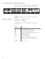
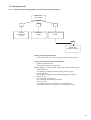
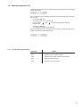
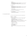
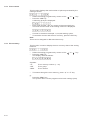
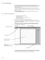
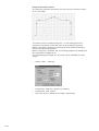
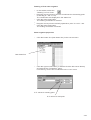
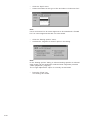
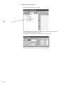
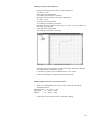
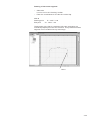
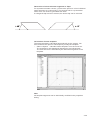
Contents:
Page:
Part 4: Programming Instructions for Class 739
Programme version:
Contents:
Page:
1.
Programming of 739-23 . . . . . . . . . . . . . . . . . . . . . . . . . . . . . . . . . . . . . . . . .
3
1.1
Introduction . . . . . . . . . . . . . . . . . . . . . . . . . . . . . . . . . . . . . . . . . . . . . . . .
Operating elements of the key bar (control panel) . . . . . . . . . . . . . . . . . . . . . . . .
3
4
1.3
1.3.1
1.3.2
Operating mode . . . . . . . . . . . . . . . . . . . . . . . . . . . . . . . . . . . . . . . . . . . . .
Structure of sewing programme and setting and test programmes . . . . . . . . . . . . . . . .
Starting of sewing machine programme . . . . . . . . . . . . . . . . . . . . . . . . . . . . . . . .
5
5
6
1.4
1.4.1
1.4.2
1.4.3
1.4.4
1.4.5
1.4.6
Setting programmes(F3) . . . . .
List of setting programmes. . . . .
Measuring of transponder reading
Measuring of “needle position” . .
Edge cutter zero position. . . . . .
Piece counter . . . . . . . . . . . .
Error memory . . . . . . . . . . . .
.
.
.
.
.
.
.
7
7
8
8
9
10
10
1.5
Default parameter settings (F4). . . . . . . . . . . . . . . . . . . . . . . . . . . . . . . . . . . .
11
1.6
1.6.1
1.6.2
1.6.3
1.6.4
1.6.5
1.6.6
1.6.7
1.6.8
1.6.9
1.6.10
Multitest (F2) . . . . . . . . . . . . . . . . . . . .
Display of machine class and software version
Display of input change . . . . . . . . . . . . . .
Switching of outputs . . . . . . . . . . . . . . . .
Testing of sewing motor . . . . . . . . . . . . . .
Testing of step motors . . . . . . . . . . . . . . .
Testing of transponder reading unit . . . . . . .
Testing of key bar . . . . . . . . . . . . . . . . . .
Testing of control RAM . . . . . . . . . . . . . . .
Testing of control FLASH . . . . . . . . . . . . . .
Adjustment of bobbin thread monitor. . . . . . .
.
.
.
.
.
.
.
.
.
.
.
.
.
.
.
.
.
.
.
.
.
.
.
.
.
.
.
.
.
.
.
.
.
.
.
.
.
.
.
.
.
.
.
.
.
.
.
.
.
.
.
.
.
.
.
.
.
.
.
.
.
.
.
.
.
.
.
.
.
.
.
.
.
.
.
.
.
.
.
.
.
.
.
.
.
.
.
.
.
.
.
.
.
.
.
.
.
.
.
.
.
.
.
.
.
.
.
.
.
.
.
.
.
.
.
.
.
.
.
.
.
.
.
.
.
.
.
.
.
.
.
.
.
.
.
.
.
.
.
.
.
.
.
.
.
.
.
.
.
.
.
.
.
.
.
.
.
.
.
.
.
.
.
.
.
.
.
.
.
.
.
.
.
.
.
.
.
.
.
.
.
.
.
.
.
.
.
.
.
.
.
.
.
.
.
.
.
.
.
.
.
.
.
.
.
.
.
.
.
.
.
.
.
.
.
.
.
.
.
.
.
.
.
.
.
.
.
.
.
.
.
.
.
.
.
.
.
.
.
.
.
.
.
.
.
.
.
.
.
.
.
.
.
.
.
.
.
.
.
.
.
.
.
.
.
.
.
.
.
.
.
.
.
.
.
.
.
.
.
.
.
.
.
.
.
.
.
.
.
.
.
.
.
.
.
.
.
11
12
12
13
14
15
16
17
17
18
18
1.7
1.7.1
1.7.2
1.7.3
1.7.4
1.7.5
1.7.6
1.7.7
1.7.8
Global parameters (F1) . . . . . . . .
Piece counter . . . . . . . . . . . . . .
Sewing motor speed . . . . . . . . . .
Stitch length . . . . . . . . . . . . . . .
Setting of material clamp infeed time
Setting of initial bartack . . . . . . . .
Setting of final bartack . . . . . . . . .
Setting of initial stitch condensation .
Setting of end stitch condensation . .
.
.
.
.
.
.
.
.
.
.
.
.
.
.
.
.
.
.
.
.
.
.
.
.
.
.
.
.
.
.
.
.
.
.
.
.
.
.
.
.
.
.
.
.
.
.
.
.
.
.
.
.
.
.
.
.
.
.
.
.
.
.
.
.
.
.
.
.
.
.
.
.
.
.
.
.
.
.
.
.
.
.
.
.
.
.
.
.
.
.
.
.
.
.
.
.
.
.
.
.
.
.
.
.
.
.
.
.
.
.
.
.
.
.
.
.
.
.
.
.
.
.
.
.
.
.
.
.
.
.
.
.
.
.
.
.
.
.
.
.
.
.
.
.
.
.
.
.
.
.
.
.
.
.
.
.
.
.
.
.
.
.
.
.
.
.
.
.
.
.
.
.
.
.
.
.
.
.
.
.
.
.
.
.
.
.
.
.
.
.
.
.
.
.
.
.
.
.
.
.
.
.
.
.
.
.
.
.
.
.
.
.
.
.
.
.
.
.
.
.
.
.
.
.
.
.
.
.
.
.
.
.
.
.
.
.
.
.
.
.
.
.
.
19
19
20
20
21
21
22
23
24
. . . . .
. . . . .
position
. . . . .
. . . . .
. . . . .
. . . . .
.
.
.
.
.
.
.
.
.
.
.
.
.
.
.
.
.
.
.
.
.
.
.
.
.
.
.
.
.
.
.
.
.
.
.
.
.
.
.
.
.
.
.
.
.
.
.
.
.
.
.
.
.
.
.
.
.
.
.
.
.
.
.
.
.
.
.
.
.
.
.
.
.
.
.
.
.
.
.
.
.
.
.
.
.
.
.
.
.
.
.
.
.
.
.
.
.
.
.
.
.
.
.
.
.
.
.
.
.
.
.
.
.
.
.
.
.
.
.
.
.
.
.
.
.
.
.
.
.
.
.
.
.
.
.
.
.
.
.
.
.
.
.
.
.
.
.
.
.
.
.
.
.
.
.
.
.
.
.
.
.
.
.
.
.
.
.
.
.
.
.
.
.
.
.
.
.
.
.
.
.
.
.
.
.
.
.
.
.
.
.
.
.
.
.
.
.
.
.
.
.
.
.
.
.
.
.
.
.
.
.
.
.
.
.
.
.
.
.
.
.
.
.
.
.
.
.
.
.
.
.
.
.
.
.
.
.
.
.
.
.
.
.
.
.
.
.
.
.
.
.
.
.
.
.
.
.
Contents:
Page:
1.7.9
1.7.10
1.7.11
1.7.12
Switching on/off of thread monitor . . .
Setting of reduced sewing motor speed
Setting of edge cutter speed. . . . . . .
Setting of suction delay. . . . . . . . . .
.
.
.
.
25
25
26
26
1.8
Special functions for the repair of a thread breakage . . . . . . . . . . . . . . . . . . . . . .
27
1.9
Tread breakage in seam (needle thread) . . . . . . . . . . . . . . . . . . . . . . . . . . . . . .
27
1.10
1.10.1
Dispays and error messages . . . . . . . . . . . . . . . . . . . . . . . . . . . . . . . . . . . . .
Error messages . . . . . . . . . . . . . . . . . . . . . . . . . . . . . . . . . . . . . . . . . . . . . .
28
28
1.11
Loading of programme in control system . . . . . . . . . . . . . . . . . . . . . . . . . . . . .
29
A.1
Appendix . . . . . . . . . . . . . . . . . . . . . . . . . . . . . . . . . . . . . . . . . . . . . . . . . .
Inputs and Outputs . . . . . . . . . . . . . . . . . . . . . . . . . . . . . . . . . . . . . . . . . . . .
30
30
2.
2.1
2.2
2.3
2.4
2.5
2.6
2.6.1
Dacs739 software . . . . . . .
Introduction . . . . . . . . . . . .
System requirements . . . . . .
Installation of Dacs739 . . . . .
Starting of Dacs739 . . . . . .
Help options . . . . . . . . . . .
Dacs739 tutorial . . . . . . . . .
Generation of a seam contour .
31
31
31
32
32
33
34
34
.
.
.
.
.
.
.
.
.
.
.
.
.
.
.
.
.
.
.
.
.
.
.
.
.
.
.
.
.
.
.
.
.
.
.
.
.
.
.
.
.
.
.
.
.
.
.
.
.
.
.
.
.
.
.
.
.
.
.
.
.
.
.
.
.
.
.
.
.
.
.
.
.
.
.
.
.
.
.
.
.
.
.
.
.
.
.
.
.
.
.
.
.
.
.
.
.
.
.
.
.
.
.
.
.
.
.
.
.
.
.
.
.
.
.
.
.
.
.
.
.
.
.
.
.
.
.
.
.
.
.
.
.
.
.
.
.
.
.
.
.
.
.
.
.
.
.
.
.
.
.
.
.
.
.
.
.
.
.
.
.
.
.
.
.
.
.
.
.
.
.
.
.
.
.
.
.
.
.
.
.
.
.
.
.
.
.
.
.
.
.
.
.
.
.
.
.
.
.
.
.
.
.
.
.
.
.
.
.
.
.
.
.
.
.
.
.
.
.
.
.
.
.
.
.
.
.
.
.
.
.
.
.
.
.
.
.
.
.
.
.
.
.
.
.
.
.
.
.
.
.
.
.
.
.
.
.
.
.
.
.
.
.
.
.
.
.
.
.
.
.
.
.
.
.
.
.
.
.
.
.
.
.
.
.
.
.
.
.
.
.
.
.
.
.
.
.
.
.
.
.
.
.
.
.
.
.
.
.
.
.
.
.
.
.
.
.
.
.
.
.
.
.
.
.
.
.
.
.
.
.
.
.
.
.
.
.
.
.
.
.
.
.
.
.
.
.
.
.
.
.
.
.
.
.
.
.
.
.
.
.
.
.
.
.
.
.
.
.
.
.
.
.
.
.
.
.
.
.
.
.
.
.
.
.
.
.
.
.
.
.
.
.
.
.
.
.
.
.
.
.
.
.
.
.
.
.
.
.
.
.
.
.
.
.
.
.
.
.
.
1. Programming of 739
1.1 Introduction
This programming manual includes instructions for the safe and
economical handling of the new “DAC” (Dürkopp Adler Control) control
system.
Programming convenience
The following functions must be programmed by the user.
– Display/delete piece counter
– Sewing motor speed
– Stitch length
– Initial bartack
– Final bartack
– Initial stitch condensation
– End stitch condensation
– Switch thread monitor on/off
Setting and test programmes
The DAC includes the comprehensive functions of the
MULTITEST testing and monitoring software.
The system is controlled by a microcomputer, which also monitors the
sewing process and indicates incorrect operation and errors.
Errors and test results are displayed on a 8-digit LED display with 7
segments. During normal operation, the display shows data regarding
the operation of the unit and the sewing process.
If an error occurs in the operation or the sewing process, the current
function is terminated.
In certain cases the main switch must be switched off in order to
eliminate an error for safety reasons.
Certain error messages are designated for service personnel only.
Special programmes simplify the mechanical configuration and
make it possible to quickly check input and output components without
the need for additional measuring devices.
4-3
1.2. Operating elements of the key bar (control panel)
For the input and output of data, the machine is equipped with a key
bar
including an 8-digit display, which is divided into 3 distinct blocks.
Display
During the standard programme run, the display is structured as
follows:
left 3 digits:
sewing machine class
centre 2 digits: no display
right 3 digits:
piece counter
If a test programme is activated, the display shows various other
parameters.
Key/
key groups
OK
0 to 9
Key for the selection of a function
Start key for the infeed of a template
Key for the selection of a function
Cancellation of sewing process/sewing machine is
reset to initial position
Confirmation of an entry
Entry of numerical values
á
â
Modification of settings in indicated direction
Modification of settings in indicated direction
F1, F2,
F3, F4
Function keys
S
ESC
4-4
Function
1.3 Operating mode
1.3.1
Structure of sewing programme and setting and test programmes
Switch on
main switch
F1
F2
F3
Global
parameters
(1XX)
Multitest
(2XX)
Setting programmes
(3XX)
F4
Parameter
default settings
Calling of global parameters
– Prior to the start of a new sewing process, press “F1” key.
Calling of setting and test programmes
– Switch on main switch.
The control system is initialised.
During display of “739 23 A00", press one of the following keys:
– Press “F2” key.
The display changes to the test programmes group.
– Press “F3” key.
The display changes to the setting programmes group.
– Press “9” key.
The machine runs slower.
For checking and testing purposes.
– Press “8” key.
If a material clamp is inserted, it is sewed again.
Cancel function by switching off the sewing machine.
4-5
1.3.2
Starting of sewing machine programme
–
Switch on the main switch.
The control system is initialised.
The start message is displayed.
To operate the sewing machine, the sewing axes must first be
positioned in the reference position.
CAUTION!
The reference run must be carried out by the operator.
CAUTION Risk of breakage!
Do not insert a material clamp during the reference run.
The following display indicates that a reference run is necessary:
To manually remove a material clamp that is inserted in the machine,
press the arrow keys “ ” and “ ”.
– Press the “OK” key.
The reference run is carried out.
After successful referencing, the display changes to:
After 0.5 seconds, the machine programme changes to operating
mode.
4-6
1.4 Setting programmes (F3)
Press the F3 function key to call the setting programmes. The display
reads as follows:
Prior to executing the setting programmes, the sewing axes must be
referenced.
– Press the “OK” key.
The reference run is carried out.
– Use the keys “ ” and “ ” to select the required setting
programme.
– Press the “OK” key.
The setting programme is started.
The first digits show the activated menu function, while the last three
digits indicate the selected function.
1.4.1
List of setting programmes
Number
301
302
303
304
305
Name
Measuring of transponder reading position
Measuring of needle position
Measuring of edge cutter zero position
Display of DA counter
Display of error memory
4-7
1.4.2
Measuring of transponder reading position
This setting programme is used to adjust the reading position of the
transponder in the material clamp.
Operating steps
– Insert the setting template into the X-guide of the sewing machine.
– Select the setting programme by means of the “ ” or “ ” key.
– Press the “OK” key.
The setting programme is started.
The X and Y axes are moved to the current transponder reading
position.
– To select a direction, press the corresponding key.
“1" key: X position
”2" key: Y position
Example: Change of X direction
–
–
–
1.4.3
Press key “á” or “â”.
The position for the reading of the transponder is moved in the
selected direction.
The last three digits of the display indicate the distance from the
original position in steps of 0.5 mm.
Press the “OK” key.
The new position is saved.
Press the “ESC” key.
The system returns to the programme for basic settings (300).
Measuring of needle position
This setting programme allows for the adjustment of the needle
position in relation to the material clamp.
–
–
–
–
4-8
Insert the setting template into the X-guide of the sewing machine.
Select the setting programme by means of the “ ” or “ ” key.
Press the “OK” key.
The setting programme is started.
The X and Y axes are moved to the current needle position.
To select a direction, press the corresponding key.
“1" key: X position
”2" key: Y-position
Example: Change of Y position
–
Press “3”.
Press “á” or “â”.
The needle position is moved in the selected direction and relative
to the material clamp in steps of 1/10 mm.
The last three digits of the display indicate the distance from the
original position.
or
– Press “4”.
Press “á” or “â”.
The needle position is moved in the selected direction and relative
to the material clamp in steps of 5/10 mm.
The last three digits of the display indicate the distance from the
original position.
–
Press the “OK” key.
The new position is saved and the system returns to the
programme for basic settings (300).
or
– Click the “ESC” key.
The system returns to the programme for basic settings (300)
without saving the new position.
1.4.4
Edge cutter zero position
This function is used to define the zero position of the edge cutter.
–
–
–
–
–
Select the setting programme by means of the “ ” or “ ” key.
Press the “OK” key.
The edge cutter is moved to its initial position.
Press the “á” or “â” key.
The zero position is moved into the selected direction.
The last three digits of the display show the distance from the initial
position.
Adjust the zero position in such a way that the edge cutter is
pointing straight ahead.
Press the “OK” key.
The new position is saved.
Press the “ESC” key.
The system returns to the setting programme for basic settings
(300).
4-9
1.4.5
Piece counter
This function displays the total number of pieces processed by the
sewing machine.
–
–
Select the setting programme by means of the “
Press the “OK” key.
A following prompt is displayed:
–
Enter code number “???” by means of the numerical keys.
The total counter value of the sewing machine is displayed.
” or “
” key.
Counter in the above example: 1,234,500 sewing cycles.
– To reset the counter and the error memory, press the “F4” key.
Note
This menu is designed for DA technicians only.
1.4.6
Error memory
This function is used to display the error memory data of the sewing
machine.
–
–
Select the setting programme by means of the “
Press the “OK” key.
The display reads as follows:
Symbols:
“nn”
“GG”
“NNN”
–
” or “
” key.
Error memory number (1 - 32)
Error group
Error number
To browse through the error memory, press “á” or “â” key.
or
– Press the “ESC” key.
The system returns to the programme for basic settings (300).
4-10
1.5 Default parameter settings (F4)
To reset the unit to the default parameters, press the “F4” key (default
parameters). The display reads as follows:
The following functions are completed:
– Internal memory is initialised.
– Error memory is deleted.
– Default values are loaded.
1.6 Multitest (F2)
If the “F2” key is pressed immediately after the main switch is witched
on, the machine changes to test mode.
The following test programmes are available:
No.
201
202
203
204
205
206
207
208
209
210
211
Name
Display of the software version
Testing of control inputs
Testing of control outputs
Testing of sewing motor
Testing of positioning by means of the step motors
Testing of CAN BUS
Testing of transponder reading unit
Testing of key bar
Testing of control RAM
Testing of control FLASH
Setting of hook thread monitor (if installed)
Operating steps
– Switch on main switch.
The control system is initialised.
– Press the F2 function key while “739 23 00" is displayed.
After a display test, the display changes to the group of setting
programmes.
4-11
1.6.1
Display of machine class and software version
No entries can be made in this test programme.
It is exclusively designed to query the machine class and the current
software version.
Operating steps
– Switch to test mode (see chapter 1.6)
– Select the test programme by means of the “
– Press the “OK” key.
The machine class is displayed.
–
Press the “OK” key.
The software version is displayed.
–
Press the “OK” key.
The date of the software is displayed.
” or “
” key.
Press “OK” key.
The system returns to the basic multitest programme.
1.6.2
Display of input change
This test programme monitors the entire input picture for changes. If a
change occurs, the input number and the switching status are
displayed.
Operating steps
– Switch to test mode (see chapter 1.6)
– Select the test programme by means of the “
– Press the “OK” key.
– Enter input manually.
The display reads e.g.:
–
Input No. 21 changed to “Off” status.
For inputs, see appendix A.1
4-12
” or “
” key.
1.6.3 Switching of outputs
In this test programme, you have the option to individually switch the
outputs. The change of a switch is indicated in the display.
Operating steps
– Switch to test mode (see chapter 1.6)
– Select the test programme by means of the “ ” or “ ” key.
– Press the “OK” key.
– Select the output with the “ ” or “ ” key.
– Change the switching status by means of the “á” or “â” key
(ON-OFF).
Example: Testing of output 16
Output 16 is switched to “ON” status.
The output status is not altered upon change to another output number.
Therefore, you have the option to set up any possible combination.
After exiting the test mode, all outputs are reset to “OFF”.
For outputs, see appendix A.1
1.6.4
Testing of sewing motor
This option allows for the testing of the sewing motor.
Operating steps
– Switch to test mode (see chapter 1.6)
– Select the test programme by means of the “ ” or “ ” key.
– Press the “OK” key.
The sewing motor is called from the serial interface and initialised.
After successful initialisation,
is displayed. If an error occurs during initialisation, the respective
error code is displayed.
–
Press the “OK” key.
The display shows three digits of the 9-digit sewing motor software
version.
4-13
–
Press the “OK” key.
The display shows three digits of the 9-digit sewing motor software
date code.
–
Press the “OK” key.
The status of the communication with the sewing motor is
displayed.
–
Press the “OK” key.
The error status of the sewing motor is displayed.
–
Press the “OK” key.
The error status message is acknowledged.
–
–
is displayed. The sewing motor can now be tested at a set speed.
Press key “á” or “â” to select the speed
(200 to 4000 r.p.m. in steps of 200 r.p.m.).
Press the “OK” key.
The sewing motor is started at the pre-selected speed.
The speed is displayed to the right of the display (3 digits) in 100
r.p.m.
Press the “ESC” key.
The sewing motor is stopped and reset to the basic multitest
programme.
–
–
4-14
1.6.5
Testing of step motors
This option allows for the testing of the step motors.
CAUTION!
To complete the test programme, the axes must be referenced.
Operating steps
–
–
–
–
Insert the setting template into the X-guide of the sewing machine.
Switch to test mode (see chapter 1.6).
Select the test programme by means of the “ ” or “ ” key.
Press the “OK” key.
The following data is displayed:
–
Press the “OK” key.
The reference run is started.
After completion of the reference run, the three step motor axes
complete 50 test cycles each.
The control checks whether the reference position has been reached
without step losses. If no step loss has occurred, the display reads as
follows:
If step losses have occurred, the display reads as follows:
The figure before “Err” indicates the axis/axes where a step loss
occurred.
Display
1
2
3
4
5
6
7
–
Axis
X axis
Y axis
X and Y axes
Z axis
X and Z axes
Y and Z axes
X and Y and Z axes
Press “OK” key.
The system returns to the basic multitest programme.
4-15
1.6.6
Testing of transponder reading unit
This programme allows for the testing of the transponder reading unit.
Operating steps
– Switch to test mode (see chapter 1.6).
– Select the test programme by means of the “ ” or “
– Press the “OK” key.
The transponder reading unit is initialised.
Upon correct initialising the display changes to:
” key.
If initialising could not be carried out, the following error code is
displayed:
–
Press the “OK” key.
The 9-digit software version number of the transponder reading
unit is displayed in three steps. Continue by pressing the “OK” key.
The display switches to:
The control system waits for 20 seconds for a transponder to be read.
– Insert setting template into the sewing machine and move it across
the aerial within these 20 seconds.
The transponder is read, and the display reads as follows:
If errors occur during the reading of the transponder, the display reads
as follows:
4-16
1.6.7
Testing of key bar
With this test programme, the individual keys of the operating panel
can be tested.
Operating steps
– Switch to test mode (see chapter 1.6).
– Select the test programme by means of the “
– Press the “OK” key.
The test programme is started.
– Press the individual keys.
Example: “F1" function key
–
1.6.8
” or “
” key.
Press the “ESC” key.
The system returns to the basic multitest programme.
Testing of control RAM
This option allows for the testing of the RAM.
Operating steps
– Switch to test mode (see chapter 1.6).
– Select the test programme by means of the “
– Press the “OK” key.
The test programme is started.
The display reads as follows:
” or “
” key.
Display if OK:
Display if error occurred:
–
Press the “OK” key.
The NV-RAM capacity of the control system is displayed.
DAC2b
DAC2c
4-17
1.6.9
Testing of control FLASH
This option allows for the testing of the flash memory.
Operating steps
– Switch to test mode (see chapter 1.6).
– Select the test programme by means of the “
– Press the “OK” key.
The test programme is started.
The display reads as follows:
” or “
” key.
Display if OK:
Display if error occurred:
1.6.10 Setting of the bobbin thread monitor (optional)
With this test programme, the sensitivity of the remaining thread
monitor (RTM) can be adjusted.
Operating steps
– Switch to test mode (see chapter 1.6)
– Select the test programme by means of the “
– Press the “OK” key.
The test programme is started.
The display reads as follows:
” or “
” key.
The remaining thread monitor is initially set to its lowest sensitivity.
When the light barrier is activated, a counter displayed in the last three
digits of the display, is started.
–
4-18
Press the “ESC” key.
The system returns to the basic multitest programme.
1.7 Global parameters (F1)
These parameters can be modified before or during every sewing
process.
The new values apply however only after the next start of the entire
process.
–
Press the “F1” key.
The machine switches to ”global parameter" mode.
–
Select the desired submode by means of the “
” or “
” key.
Note
Press the “F4” key to reset all “global parameters” to the respective
default values.
List of setting menus
No.
101
102
103
104
105
106
107
108
109
110
111
112
1.7.1
Setting
Piece counter
Setting of sewing motor speed
Setting of stitch length
Setting of template infeed
Setting of initial bartack
Setting of final bartack
Setting of initial stitch condensation
Setting of end stitch condensation
Switching on/off of thread monitor
Setting of reduced sewing speed
Setting of edge cutter speed
Setting of suction delay
Piece counter
The piece counter parameter can be reset to “0" by the operator.
Simultaneously, the counter in the main display (daily counter) is reset.
Operating steps
– Select menu with the “ ” or “
– Press the “OK” key.
– Press the “F4” key.
The counter is reset to “0".
” key.
4-19
1.7.2
Sewing motor speed
With this parameter, the sewing motor speed can be adjusted to suit
individual requirements.
Operating steps
– Select menu with the “ ” or “ ” key.
– Press the “OK” key.
– Press key “á” or “â” to select the speed
(200 to 4000 r.p.m in steps of 200 r.p.m.).
– Press the “OK” key.
The set speed is applied.
Note
The speed settings in the individual transponders are ignored.
If the speed is set to “0", the machine sews according to the speed
settings of the transponders.
1.7.3
Stitch length
With this parameter, the stitch length can be adjusted.
Operating steps
– Select menu with the “ ” or “ ” key.
– Press the “OK” key.
– Set the desired stitch length with the “á” or ”â” key
(2.0 to 3.0 mm, step width 0.1 mm).
– Press the “OK” key.
The set stitch length is transferred to the control system.
Note
The stitch length settings in the individual transponders are ignored.
If the stitch length is set to “0", the machine sews according to the
stitch length settings of the transponders.
4-20
1.7.4
Setting of material clamp infeed time
With this parameter, the time during which the X axis is running to feed
a new template into the machine is set.
Operating steps
– Select menu with the “ ” or “ ” key.
– Press the “OK” key.
– Set the desired time with the “á” or “â” key
(0 to 60 seconds).
Example: 30 seconds
–
1.7.5
Press the “OK” key.
The set time is transferred to the control system.
Setting of initial bartack
With this parameter, the initial bartack for the contour to be sewed can
be defined.
The first digit of the display indicates the type of initial bartack, while
the second digit indicates the number of stitches in the tack.
Tack type: 1 = Single tack
2 = Double tack
Number of stitches
0 to 20 stitches
Example: Tack type = 1, number of stitches = 6
Note
If the tack type is set to “0", the machine sews according to the tack
settings of the transponders.
Operating steps
– Select menu with the “ ” or “ ” key.
– Press the “OK” key.
– Set the desired tack type with the “1" or ”2" key.
– Set the desired number of stitches in the tack with the “á” or “â”
key.
– Press the “OK” key.
The set values are transferred to the control system.
or
– Press the “ESC” key.
The changes are cancelled.
4-21
1.7.6
Setting of final bartack
With this parameter, the final bartack for the contour to be sewed can
be defined.
The first digit of the display indicates the type of final bartack, while the
second digit indicates the number of stitches in the tack.
Tack type: 1 = Single tack
2 = Double tack
Number of stitches
0 to 20 stitches
Example: Tack type = 1, number of stitches = 6
Note
If the tack type is set to “0", the machine sews according to the tack
settings of the transponders.
Operating steps
– Select menu with the “ ” or “ ” key.
– Press the “OK” key.
– Set the desired tack type with the “1" or ”2" key.
– Set the desired number of stitches in the tack with the “á” or “â”
key.
– Press the “OK” key.
The set values are transferred to the control system.
or
– Press the “ESC” key.
The changes are cancelled.
4-22
1.7.7
Setting of initial stitch condensation
With this parameter, the initial stitch condensation for the contour to be
sewed can be defined.
The first digit of the display indicates the number of stitches, while the
last digits in the display indicate the stitch length for the stitch
condensation.
Number of stitches
0 to 20 stitches
Stitch length
0.5 mm to 2.3 mm in 8 steps
Example: Number of stitches = 5, stitch length = 0.5 mm
Note
If the stitch length is set to “0", the machine sews according to the
stitch condensation settings of the transponders.
Operating steps
– Select menu with the “ ” or “ ” key.
– Press the “OK” key.
– Set the desired number of stitches with the “á” or “â” key.
– Set the desired stitch length with keys “1" to ”8".
– Press the “OK” key.
The set values are transferred to the control system.
or
– Press the “ESC” key.
The changes are cancelled.
4-23
1.7.8
Setting of end stitch condensation
With this parameter, the end stitch condensation for the contour to be
sewed can be defined.
The first digit of the display indicates the number of stitches, while the
last digits in the display indicate the stitch length for the stitch
condensation.
Number of stitches
0 to 20 stitches
Stitch length
0.5 mm to 2.3 mm, in 8 steps
Example: Number of stitches = 5, stitch length = 0.5 mm
Note
If the stitch number is set to “0", the machine sews according to the
stitch condensation settings of the transponders.
Operating steps
– Select menu with the “ ” or “ ” key.
– Press the “OK” key.
– Set the desired number of stitches with the “á” or “â” key.
– Set the desired stitch length with keys “1" to ”8".
– Press the “OK” key.
The set values are transferred to the control system.
or
– Press the “ESC” key.
The changes are cancelled.
4-24
1.7.9
Switching on/off of thread monitor
With this parameter, the thread monitor can be switched on or off
respectively.
Operating steps
– Select menu with the “ ” or “ ” key.
– Press the “OK” key.
The selected setting are displayed.
–
–
Select the desired setting with the “0" or ”1" key.
0 = Thread monitor switched off
1 = Thread monitor switched on.
Press the “OK” key.
The set values are transferred to the control system.
or
– Press the “ESC” key.
The changes are cancelled.
1.7.10 Setting of reduced sewing motor speed
With this parameter, you have the option to adjust the reduced sewing
motor speed.
If the parameter is set to “0", the reduced speed saved in the
transponder is applied.
The speed can be adjusted in steps of 200 r.p.m.
Operating steps
– Select menu with the “ ” or “ ” key.
– Press the “OK” key.
The selected settings are displayed.
–
–
Set the desired reduced speed with the “á” or ”â” key.
Press the “OK” key.
The set value is saved.
or
– Press the “ESC” key.
The changes are cancelled.
4-25
1.7.11 Setting of edge cutter speed
With this parameter, you have the option to set the speed of the edge
cutter.
If the parameter is set to “0", the edge cutter speed saved in the
transponder is applied.
The speed can be adjusted in steps of 200 r.p.m.
Operating steps
– Select menu with the “ ” or “ ” key.
– Press the “OK” key.
The selected settings are displayed.
–
–
Set the desired speed with the “á” or “â” key.
Press the “OK” key.
The set value is saved.
or
– Press the “ESC” key.
The changes are cancelled.
1.7.12 Setting of suction delay
With this parameter, you have the option to adjust the delay until the
suction unit is switched on.
If the parameter is set to “0", the switching delay saved in the
transponder is applied.
The switching delay is set in % values of the material clamp seam
length.
Operating steps
– Select menu with the “ ” or “ ” key.
– Press the “OK” key.
The selected setting are displayed.
–
–
Set the desired switch-on delay with the “á” or “â” key.
Press the “OK” key.
The set value is saved.
or
Press the “ESC” key.
The changes are cancelled.
4-26
1.8 Special functions for the repair of a thread breakage
After a thread breakage has occurred, the sewing machine must be
switched off, re-threaded and then switched on again.
To insert the needle thread and the bobbin thread under the thread
cutter hook after threading, proceed as follows:
– Press the “1" key.
The display reads as follows:
The thread cutter is activated for one second. Within this time, both
threads can be placed under the hook.
After one second, the basic display appears.
1.9 Thread breakage in seam (needle thread)
If a thread breakage occurs in the seam, the sewing process is
interrupted and an error / warning message is displayed.
Note
The “Err” display is blinking.
(Error group 0, error number 1 = needle thread broken)
4-27
1.10 Displays and error messages
If an error or a warning occurs, a respective message is displayed at
the key bar.
The various errors are displayed in the form of 5-digit codes. The “Err”
display is blinking to clearly indicate that an error occurred.
1.10.1 Error messages
Group
Number
0
1
2
1
1
2
5
1
2
3
4
8
16
24
50
4-28
Description
Thread breakage
Needle thread
Bobbin thread
Thread monitor error
Bobbin thread is used up.
Re-wind bobbin
Needle thread is broken
Re-thread needle thread
Step motor error
Z axis referencing error.
The Z motor did not reach its reference point
within 20 seconds.
Y axis referencing error.
The Y motor did not reach its reference point
within 20 seconds.
YZ referencing error.
The Y motor and/or the Z motor did not reach
its/their reference point within 20 seconds.
X axis referencing error.
The X motor did not reach its reference
position (gauge pin) within 20 seconds upon
setting of a position (301, 302) or upon testing
of the step motor axes (2059).
XY axes system positioning error.
The XY system did not reach its target position
within 5 seconds upon positioning.
Z axis positioning error.
The Z axis did not reach its target position
within 5 seconds upon positioning.
Positioning error.
The XYZ system did not reach its target
position within 5 seconds upon positioning.
Step motor high-level error.
Step motor high-levels indicate a hardware
error.
Group
Number
6
1
2
3
4
5
6
7
8
9
10
11
50
7
1
2
3
4
10
0
1
4
8
Description
Sewing motor error
Poor connection
Communication interrupted
Illegal command
Command buffer full
Protocol error
Timeout
Sending register 422
NAK
Drive not ready
UART not ready
Hardware error
Sewing motor timeout upon thread cutting
process
Internal errors
Contour data memory full.
The contour requires more than 1600 stitches.
Error upon cycle calculation.
Incorrect direction of rotation in the cycle, or
calculation overflow.
Error, NV-RAM data lost.
Default values are activated, reference
positions must be set again.
Call menus 301, 302 and 303.
Power fail input is activated.
Insufficient supply voltage to the sewing
machine.
Transponder errors
Zero-point gauge pin recognised, but
transponders could not be read.
Communication timeout Transponder reading
unit.
Communication with the transponder module is
disrupted. The module does not respond.
Transponder content is damaged. Incorrect
transponder checksum.
Communication error with the transponder
reading unit.
Transfer is disrupted. Incorrect transfer
checksum.
1.11 Loading of the programme to the control system
The DAK 2A/B control system is equipped with a flash memory. It is
thus possible to transfer the software data via a boot box or a PC to the
control system.
4-29
Appendix
A.1 Inputs and Outputs
Input
S1
S4
S5
S8
Output
Y1
Y2
Y3
Y4
Y5
Y6
4-30
Description
Reference switch Z axis
Reference switch Y axis
Reference switch X axis
Needle thread monitor
Description
Blower (edge cutter on)
Release thread tension
Thread cutter on
Vacuum suction on
Thread clamp on (thread scissors)
Release thread clamp (thread scissors)
2. Dacs739 software
2.1 Introduction
The Dacs739 software is a user-friendly tool to create your own sewing
templates for the 739-23 sewing machine.
A two-dimensional graphics editor allows for the design or modification
of seam contours by mouse-click or by numerical entries.
The software package includes a comprehensive help function.
Additional functions:
•
•
•
•
•
•
The programme carries out plausibility checks of all entries.
Calculation of the ideal material clamp contour after completion of
the seam contour by the programme.
Calculation of the fullness contour
The material clamp contour can be printed out on a scale of 1:1.
The seam contour, material clamp contour and fullness contour can
be written to a transponder by means of a read/write device.
All data of the material clamps can be archived, reread and
modified.
2.2 System requirements
Dacs739 requires the following hardware and software components:
•
•
•
•
•
•
•
•
•
PC with 486 or Pentium processor
MS Windows 95, 98 or NT version 3.5.1 or later
Minimum 16 MB RAM
CD-ROM drive or 3.5 “ floppy disk drive
10 MB free memory on hard disk
Free serial port
VGA graphic card, min. 600 x 800 pixels, 256 colours
Mouse
Windows-compatible printer including driver
4-31
2.3 Installation of Dacs739
–
–
–
Terminate all programmes in Windows and deactivate all virus scan
programmes.
Place the Dacs739 CD into your CD-ROM drive
or
insert disk no. 1 into your 3.5" floppy drive.
Follow the instructions of your platform:
For Windows NT 3.5.1, select the “Run” command from the “File”
menu of the programme manager.
–
–
–
For Windows 95, 98 or Windows NT 4.0, select the “Run” command
from the start menu.
Enter d:\setup.exe (whereby d: is your CD-ROM drive)
or
enter a:\setup.exe and click “OK”.
The “Welcome” screen is displayed. Follow the instructions on the
screen.
Click “Next”.
Confirm the default values for target drive and folder displayed
under “Target folder”.
Click “Browse” or enter a different folder and/or drive.
–
Click “Next”.
Confirm the programme folder displayed under “Programme
folder”,
or
enter a different folder.
–
–
Click “Next” to start the installation.
When asked to do so, insert the next disk into the floppy disk drive.
–
Follow the instructions for your platform:
2.4 Starting of Dacs739
Open the programme group “Dacs739" in the programme manager
of Windows NT 3.5.1 and double-click the ”Dacs739" programme
icon.
In Windows 95, 98 or Windows NT 4.0, click the start menu and
select “Programmes > Dacs739> Dacs739".
4-32
2.5 If you need help ...
Dacs739 includes a comprehensive online help facility. It can be called
at any time by pressing “F1”.
Contents of help facility
The help topics are divided into five categories. Each category is
represented by a button in the help contents window.
The following table provides an overview of the information available in
the individual categories.
Button
Topics
Introduction
Reference to further help
Operation
List of the
programme functions
Useful hints
Dialogs
Menues
Description of the menu commands
Context-related help
Use the context-related help
to call up the relevant help texts
for a specific Dacs739 option.
If the “Context help” button is selected from the toolbar, the mouse
pointer changes to an arrow with a question mark. Click anywhere in
the Dacs739 window, e.g. a button in the toolbar.
The help topic corresponding to the clicked object is displayed.
4-33
2.6 Dacs739 tutorial
This practical tutorial allows you to familiarize yourself with the
Dacs739 software within a very short time. It covers all the basic steps
that must be carried out for the creation and archiving of your own
individual contours.
The tutorial includes additional information on any given topic and
indicates, where the respective chapter can be found in the online help
facility of Dacs739.
Dacs739 support multi-tasking so that several documents can be
processed simultaneously.
2.6.1
Creation of a seam contour
–
Start the Dacs739 software
(see chapter 2.4).
The programme window is opened.
– Select “File > New”.
The document window is divided into two parts.
To the left, a tree diagram is displayed, showing the sections of the
seam contour. To the right, a CAD design window for the seam contour
to be drawn is displayed.
Below the menu bar, the “standard” toolbar is displayed, while the
“drawing” toolbar is located to the right. At the bottom of the screen,
the “status bar” is displayed.
Menu bar
“Drawing” toolbar
“Standard" toolbar
Tree diagram
Entry field for the
seam contour
Zero point P0
Origin of the
system of coordinates
Status bar
The zero point P0 is the origin of the coordinates system. It is always
located in the bottom left corner of the CAD window. The coordinates
run from this point, increasing upwards and to the right.
4-34
Additional information
For more information, click the object you would like to know more
about in the diagram.
Import of background pictures
Depending on the application, (waistband extension or flap), a
background picture can be imported.
This background picture is very helpful for the entry of the seam
contour.
– Open “File > HPGL import”.
– Select a file:
flap_pattern.plt for the entry of a flap pattern
bottom seam start/end
or
waist-band_pattern.plt for the entry of a waistband extension.
4-35
Entry of the seam contour
The following exercise introduces you to the entry of a seam contour
for a curved flap.
The seam contour is entered as a line, i.e. the starting point of a
segment corresponds to the end point of the preceding segment.
When a segment is deleted, its starting point becomes the starting
point of the following segment.
When a segment is inserted, the next existing segment is divided into
two segments of straight lines.
The segment type (straight, arc of circle) can be modified at a later
stage.
4-36
–
Select “Tools > Settings".
–
–
–
Activate the “Direction” option in the dialog.
Activate the “Grid” option.
Enter 5.0 mm for “Width” and “Height” respectively.
Drawing of first seam segment
–
–
–
–
–
In the toolbar, select the
“Drawing” icon for lines.
Drag the mouse pointer to the first coordinate for the starting point
of the flap (X = 50/ Y = 50).
The coordinates are displayed in the status bar.
Click the left mouse button.
The starting coordinate is entered.
Drag the mouse pointer vertically upwards to point X = 50/ Y = 85.
Click the left mouse button.
The ending coordinate is entered.
Seam segment properties
–
Click the bottom line (last drawn line) in the tree structure.
–
Click the right mouse button (or double-click the left mouse button)
and activate the “Properties” menu.
If necessary, correct the coordinates in the “Line” menu.
Last drawn line
X /Y values for starting point
X /Y values for end point
4-37
–
–
Click the “Style” menu.
Select the listbox for the type of line and select “Continuous line”.
Note
Use a continuous line for seam segments to be sewed and a “Dotted
line” for seam segments that are not to be sewed.
–
–
Click the “Sewing options” menu.
Activate the “Segment is sewed” option in the dialog.
Note
In the “Sewing options” dialog, a reduced sewing speed or a reduced
stitch length can be assigned to selected seam segments (see also
“Seam properties”, page 44).
The “Length adjustment” option is currently not activated.
–
4-38
Press the “Enter” key.
The settings are saved.
Drawing of second seam segment (curve)
–
–
–
–
–
–
–
Select the
icon for curve in the “Drawing” toolbar.
Drag the mouse pointer to the end point of the preceding line (X =
50/ Y = 85).
Click the left mouse button.
The starting coordinate is entered.
Drag the mouse pointer to the upper right point
X = 60/ Y = 95.
Click the left mouse button.
The ending coordinate is entered.
Drag the mouse to the left to point X = 58/ Y = 95. The radius of the
circle is generated.
Click the left mouse button.
The ending coordinate is entered.
The arc is defined by the three points P1, P2 and P3.
The radius of the arc can be modified by means of points M and
P3.
Note
To delete the last drawn segment, press the “Del” key.
4-39
Seam segment properties
–
In the tree structure, click the arc.
–
Click the right mouse button (or double-click the left mouse button)
and activate the “Properties” menu.
If necessary, correct the coordinates in the “Arc” menu.
–
Check the settings for “Style” and “Sewing options”.
Click
Arc
4-40
Drawing of next seam segment
–
–
–
–
–
–
Drag the mouse pointer to the end point of the arc
(X = 60/ Y = 95).
Click the left mouse button.
The starting coordinate is entered.
Drag the mouse pointer to the upper right point
X = 95/ Y = 102.
Click the left mouse button.
The ending coordinate is entered.
Drag the mouse to the left to the point X = 78/ Y = 95. The radius of
the circle is generated.
Click the left mouse button.
The ending coordinate is entered.
–
Click the right mouse button (or double-click the left mouse button)
and activate the “Properties” menu.
If necessary, correct the coordinates in the “Arc” menu.
–
Check the settings for “Style” and “Sewing options”.
Seam segment for the curve at the centre
–
Enter the coordinates for the curve at the centre of the flap as
described above.
Starting point = X = 95/ Y = 102
End point = X = 105/ Y = 102
Radius
= X = 100/ Y = 104
–
Check the arc properties in the “Properties” dialog.
4-41
Arcs 4 and 5
–
Enter the coordinates for the next two arcs of the flap.
Arc 4
Starting point
X = 105/ Y = 102
End point
X = 140/ Y = 95
Radius
X = 125/ Y = 95
Arc 5
Starting point
X = 140/ Y = 95
End point
X = 150/ Y = 85
Radius
X = 150/ Y = 87.5
Arc 4
Arc 5
4-42
Drawing of last seam segment
–
–
Select the
icon for line in the “Drawing” toolbar.
Enter the coordinates for the last line of the flap.
Line 6
Starting point
X = 150/ Y = 85
End point
X = 150/ Y = 50
The drawing of the flap is completed. All seam segments are
individually displayed in the tree structure. Every individual seam
segment can be modified at any later stage.
Line 6
4-43
Seam properties
–
–
In the tree structure, click “Seam”.
Click the right mouse button.
The “Seam properties” dialog is displayed.
–
Enter the desired values for the seam.
The following values are available:
Stitch length:
1.0 to 4.0 mm.
Suction delay: 0% to 93 %, in steps
Speed:
200 to 4000 r.p.m.
Reduced speed: 200 to 4000 r.p.m.
Limited speed: 200 to 4000 r.p.m.
–
Click “Seam start”.
–
Activate a “Stitch condensation” with a stitch length of
0.5 mm and 6 stitches.
The following options are available:
•
•
•
–
–
4-44
Standard = no tack / no stitch condensation
Tack/double tack 1 to 15 stitches
Stitch condensation 0.5 to 2.25 mm, 1 to 15 stitches
Click “Seam end”.
Activate a “Stitch condensation” with a stitch length of
0.5 mm and 6 stitches.
Generation of mirrored seam segments or flaps
For symmetrical seam courses, you have the option to mirror individual
seam segments to a centred line. The second half of a symmetrical
seam curve can thus be generated with ease.
If a diagonal flap has been entered, the entire flap can be mirrored.
Calculation of seam template
The seam template is calculated automatically by the system. You
have however the option to subsequently modify the template.
– Select “Objects > Calculate seam template” from the menu bar.
The template is calculated and displayed in the CAD window.
The tree structure is extended by the individual segments of the
template.
Note
All template segments can be individually modified in the properties
dialog.
4-45
Calculation of fullness contour
The fullness contour is also calculated automatically by the system.
You have the option to subsequently modify the template.
Select “Objects > Calculate fullness template” from the menu bar.
The template is calculated and displayed in the CAD window.
The individual segments of the pattern are added to the tree structure.
File properties
For every document, you have the option to save additional
information. This simplifies the file management.
– Select “File > File properties”.
– Enter your details in the available fields.
Saving of seam contour
– Select “File>Save as”.
The “DACS739\Documents” folder is opened automatically.
– Enter a name for your seam contour in the “File name” field.
(Example: Seam contour 1)
– Click the “Save” button.
4-46
Data transfer to the transponder
Seam contours, material clamp contours and fullness contours can be
transferred individually to the transponder in the “Material clamp zero
point” gauge. The “Material clamp zero point” gauge is included in the
delivery.
You have thus the option to transfer individual contours to the stitching
plate, where they can be controlled and processed.
–
–
–
–
Connect the transponder to your PC
see operating instructions of the transponder).
Place the “Material clamp zero point” gauge with the respective
transponder onto the transponder device.
Select “File > Transponder”.
According to your needs, select:
Transfer seam data, or
Transfer template data, or
Transfer fullness data.
The selected data is transferred to the transponder in the gauge.
4-47
Sample flaps and waistband extensions
In the “Documents” inventory of Dacs software, various sample files for
flaps and waistband extensions are saved.
These samples can be modified.
Caution!
Prior to modification, save the sample files under a different name.
Congratulations!
You have reached the end of this tutorial. Please remember that more
information on all topics is available from the online help.
The further procedure for the creation of material clamps is described
in
“Part 5: Instructions for material clamp manufacture class 739-23".
4-48