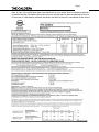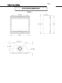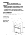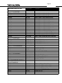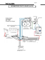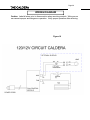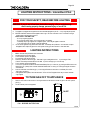
1
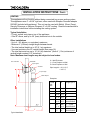
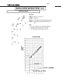
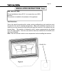
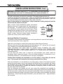
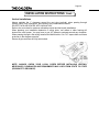
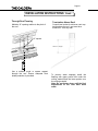
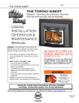
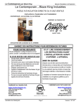
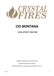
Page 1 THE CALDERA THE CALDERA DIRECT VENTED Room Heater For use with natural gas or propane USERS’ INSTALLATION OPERATION & MAINTENANCE WARNING: If the information in this manual is not followed exactly, fire or explosion may result causing property damage, personal injury or loss of life. — Do not store or use gasoline or other flammable vapors and liquids in the vicinity of this or any other appliance. — WHAT TO DO IF YOU SMELL GAS · Do not try to light any appliance. · Do not touch any electrical switch; do not use any phone in your building. · Immediately call your gas supplier from a neighbor’s phone. Follow the gas supplier’s instructions. · If you cannot reach your gas supplier, call the fire department. — Installation and service must be performed by a qualified installer, service agency or the gas supplier. This appliance may be installed in an aftermarket permanently locat ed, manufactured (mobile) home, where not prohibited by local codes. This appliance is only for use with the type of gas indicated on the rating plate. This appliance is not convertible for use with other gases, unless a certified kit is used. INSTALLER: PLEASE LEAVE THIS MANUAL WITH THE CUSTOMER CUSTOMER: PLEASE KEEP MANUAL FOR FUTURE REFERENCE Pour la version française de nos manuels S.V.P. vous référez à notre site web : www.blazeking.com Version 1.12 SIT Aug 2013 Page 2 THE CALDERA CONTENTS Page Introduction 4 General Information 5 Appliance Dimensions 6 Installation Clearances 7-9 Installation Instructions - Appliance 10 - 12 Assembly Instructions - Log Set 13-14 Installation Instructions - Venting 15-22 Rigid Venting Parts List 23-25 Intermittent Pilot & Valve Information 26-27 Wiring Diagram 28 Lighting Instructions 29-30 Handheld Thermostat Remote Control - Operation instructions 31-35 Maintenance 36-37 Servicing 38-39 Fuel Conversion 40-41 Allowed Termination Location 42 Troubleshooting 43-44 Fan Kit Installation 45-46 Replacement Parts 47-48 Warranty 49-52 Notes & Service History 53 MANUFACTURED IN CANADA BY: MANUFACTURED IN USA BY: Valley Comfort Systems Inc. 1290 Commercial Way Penticton, BC V2A 3H5 Blaze King Industries 146 A Street Walla Walla, WA. 99362 Ph# 1-250-493-7444 Email [email protected] Patents Pending Ph# 1-509-522-2730 Email [email protected] THE CALDERA Page 3 Note: A copy of the certification label is provided here for your review. Due to constant up-grades it is possible that the information shown here may not coincide with the label as attached to the unit. In the event of a discrepancy between the labels, the label on the unit is considered as the correct Page 4 THE CALDERA INTRODUCTION Thank you for purchasing the Caldera Zero Clearance Fireplace Gas Heater. The Caldera is one of the most advanced direct vented zero clearance gas heaters on the market. It is designed using the latest technology and manufactured to the highest quality. Some of the many features are: Electronic Valve Intermittent pilot & remote capability. Heater Classification It is classified as a heating appliance. Therefore, it can be operated continuously for zone heating. High Efficiency It has high efficiency; therefore, it is less expensive to operate. Adjustable Flame The flame aesthetics and heat output can be adjusted to suit the owner’s moods and heating needs. Solid Construction It is constructed mainly heavy gauge steel for long life and durability. Please read the manual carefully prior to installation and operation of the appliance. Proper installation, operation and maintenance of the appliance will provide you with many years of enjoyment. CAUTION Due to high temperatures, the appliance should be located out of traffic and away from furniture and draperies. Children and adults should be alerted to the hazards of high surface temperature and stay away to avoid burns or clothing ignition. Young children should be carefully supervised when they are in the same room as the appliance. Clothing or other flammable material should not be placed on or near the appliance. Any parts removed or opened for servicing of the appliance must be properly replaced prior to operating the appliance. The appliance must be inspected before use and at least annually by a qualified service person. More frequent cleaning maybe required due to excessive lint from carpeting, bedding material, etc. It is imperative that the control compartments, burners and circulating air passageways for the appliance be kept clean. Venting terminals shall not be recessed into a wall or siding. This gas appliance must not be connected to a chimney flue serving a separate solid fuel burning appliance. Page 5 THE CALDERA GENERAL INFORMATION APPLIANCE CERTIFICATION This appliance is tested and certified to the following US and Canadian gas appliance standards. - ANSI Z21.88-2007 / CSA 2.33-2007 Vented Gas Fireplace Heaters, - CAN/CGA-2.17-M91 Gas-Fired Appliance fo Use at High Altitudes - CSA P.4.1-02 Testing Method for Measuring Annual Fireplace Efficiency Please contact Valley Comfort or Blaze King, if you have any questions regarding the certification of this appliance. INSTALLATION CODES This appliance must be installed by a qualified gas appliance installer. The installation must conform with the local codes or, in the absence of local codes, with the current National Fuel Gas Code, ANSI Z223.1/ NFPA 54, in the US or Installation Code, CSA-B149.1, in Canada. Electrical connections and grounding must be in accordance with local codes, if any, if not, follow the current CAN/CSA C22.1 in Canada and ANSI/NFPA 70 in the US. This appliance is certified for installation in a bedroom or a bedsitting room. This appliance is only for use with the type of gas indicated on the rating plate and may be installed in an aftermarket, permanently located, manufactured (mobile) home where not prohibited by local codes. See owner’s manual for details. This appliance is not convertible for use with other gases, unless a certified kit is used. This appliance must be installed in accordance with the current Standard CAN/CSA Z240 1411, Mobile Housing, or with the Manufactured Home Construction and Safety Standard Title 24 CFR, Part 3280, or when such a standard is not applicable, ANSI/NCSBCS A225.1/NFPA 501A, Manufactured Home Installations Standard. Only for direct discharge without duct connection. This appliance must be direct vented using listed and approved Simpson Dura-Vent, Selkirk, Security or American Metal Products vent components. SPECIFICATIONS Natural Gas (NG) Propane (LP) Manifold Pressure 3.5 in. W.C. (0.9 kpa) 10.0 in. W.C. (2.5kpa) Min. Supply Pressure for Purpose of Input Adjustment 5.0 in. W.C. (1.24 kPa) 12.0 in. W.C. (3.0 kPa) Orifice Size #35 DMS #51 DMS Nominal Input Rating 35,000 - 24,000 BTU/hr (10.26 – 7.04 kW) 35000 - 26,000 BTU/hr (10.26 – 7.26 kW) Altitude 0 - 4,500 ft. (0 - 1372 m) 0 - 4,500 ft. (0 - 1372 m) Primary Air Opening closed 100% open HIGH ALTITUDE INSTALLATION When installing this appliance beyond 4500 ft. (1372 m) above sea level, the appliance must be properly de-rated and installed according to local codes, in the absence of local codes, with the current National Fuel Gas Code, ANSI Z223.1/ NFPA 54, in the US or Installation Code, CSA-B149.1, in Canada. Page 6 THE CALDERA APPLIANCE DIMENSIONS Figure 1 Page 7 THE CALDERA INSTALLATION CLEARANCES Figure 2 C D A - Internal Ceiling Height min. 60" (1524 mm) B - Internal Framing min. 45" (1143 mm) C - Sidewall Clearance min. 6" (152 mm) D - Unexposed Back & Sides min. 2" (51 mm) Mantle - See Chart Vertical Vent - 1" (25 mm) to outside surface Can be installed on a combustible surface. Page 8 THE CALDERA INSTALLATION CLEARANCES Figure 3A Minimum framing dimensions Figure 3B Mantle Clearances to Combustibles Mantle Height from Floor (B) Mantle Depth (A) Max. 50" (1270 mm) 12" (300 mm) 49" (1245 mm) 11-5/16" (287 mm) 48" (1219 mm) 10-9/16" (268 mm) 47" (1194 mm) 9-7/8" (251 mm) 46" (1168 mm) 9-3/16" (233 mm) 45" (1143 mm) 8-7/16" (214 mm) 44" (1118 mm) 7-3/4" (197 mm) 43" (1092 mm) 7-1/16" (179 mm) 42" (1067 mm) 6-5/16" (160 mm) 41" (1041 mm) 5-5/8" (143 mm) 40" 1016 mm) 4-15/16" (125 mm) 39" (991 mm) 4-3/16" 106 mm) 38" (965 mm) 3-1/2" (89 mm) 37" (940 mm) 2-13/16" (71 mm) 36" (914 mm) 2-1/16" (52 mm) 35" (889 mm) 1-3/8" (35 mm) 34" (864 mm) 11/16" (17 mm) THE CALDERA INSTALLATION CLEARANCES Figure 3C Minimum Framing Dimensions Figure 3D Minimum Framing Dimensions Page 9 Page 10 THE CALDERA INSTALLATION INSTRUCTIONS Figure 3C Cement Board Dimensions INSTALL VERTICAL HEAT SHIELD The heat shield which comes with the appliance, needs to be mounted vertically on top of the appliance. The three holes line up with the ones on top of the appliance, in front of the flue collar. Use three screws to mount the heat shield. IMPORTANT:When the heat shield is not installed, fire may result, causing property damage, personal injury or loss of life. THE CALDERA Page 11 INSTALLATION INSTRUCTIONS Cont... PRECAUTIONS This appliance must be installed by a qualified gas installer and the installation conform to applicable installation codes. This appliance needs fresh air for safe operation and must be installed so there are provisions for adequate ventilation air. Provide adequate clearance around air openings of the appliance. Never obstruct front openings. Provide adequate clearances for proper operation and servicing of the appliance. This appliance must be properly connected to a venting system. This appliance must NOT be connected to a chimney flue serving a solid-fuel appliance. LOCATING GAS FIREPLACE The venting system of this appliance must be installed in a location that is free of plumbing, electrical wiring and heating or air conditioning ducts. Select a location that is accessible for venting. See the ALLOWABLE TERMINATION LOCATIONS - page 45, in this manual. ANCHORING UNIT After determining the location, the appliance needs to be anchored to framing and floor. Attach to the floor with two screws through the holes in the bottom of the appliance (see Figure 3D) The holes are located behind the bottom louver, one on the left, one on the right. Attach to the frame by the standoffs on top of the unit (See Figure 3D) The standoffs can be adjusted by loosening the screws on top of the appliance Figure 3D THE CALDERA Page 12 INSTALLATION INSTRUCTIONS Cont... VENT TERMINATION LOCATION 1. Establish a suitable vent termination location. (See ALLOWABLE TERMINATION LOCATIONS - page 42) 2. In heavy snowfall areas make sure vent termination is located where it can not be blocked by snowfall or snow from snow removal equipment. 3. Locate vent termination away from plants, bushes or any other object on or near the vent termination that will interfere or obstruct the air flow around it. 4. DO NOT recess vent termination into walls, sidings or planters. 5.Vent terminations located below 7 ft (2130 mm) from grade level or anywhere that it is a burn hazard to the public, such as patios and balconies, must be protected with an approved termination cage. POWER CONNECTION You will need to have an electrician supply 120 volts to the area of the fireplace and terminate in the junction box inside the unit. GAS CONNECTIONS Have your gas supplier or a qualified gas fitter run a gas supply line to the gas fireplace. For your convenience the appliance has a shut-off valve and flex line installed, check with your local installation codes if this is to code. There is an access hole situated under the burner for easier access to the gas valve connection. (Left side under burner, triangular shaped) CAUTION: The appliance and its individual shutoff valve must be disconnected from the gas supply piping system during any pressure-testing of that system at test pressures in excess of 1/2 psig (3.5 kPa). The appliance must be isolated from the gas supply piping system by closing its individual manual shutoff valve during any pressure-testing of the gas supply piping system at test pressures equal to or less than 1/2 psig (3.5 kPa). Failure to do so will damage the appliance’s gas valve. Such damage is not covered by the manufacturer’s warranty. Check for proper gas supply pressure by loosening the set screw on supply pressure tap on the gas valve with a small flat tip screw driver and placing a test gauge on the tap. The minimum permissible gas supply pressure is 5 in. w.c. (1.24 kPa) for natural gas and 12.0 in. w.c. (3.00 kPa) for propane. Maximum gas supply pressure should never exceed 14.0 in. w.c. (3.48 kPa) or 1/2 psi. for both natural gas and propane. BE SURE TO TIGHTEN THE PRESSURE TAP SET SCREW AFTER CHECKING THE PRESSURE. Before connecting the appliance to the gas supply line, double check that the appliance you have purchased is designed for the gas type you are using. The gas type markings are located on the certification label and also on the appliance’s gas valve. Adequate clearance for proper installation and checking of the gas connections must be provided. All gas connections must be checked for gas leaks. Page 13 THE CALDERA ASSEMBLY INSTRUCTIONS GLASS DOOR REMOVAL Removing the Glass Door - Remove the top & bottom louvers. - Unhook the door latches found on the bottom of the firebox. - Carefully lift and remove the door. - Place the door at a safe location where it cannot be scratched or damaged. - If the glass door is damaged, it must be replaced with another glass door certified with this appliance only. - Replacement glass doors are available through your Blaze King dealer (See Replacement Parts page 47) Replacing the Glass Door - Check the condition of the glass and the gasket before installing door. - Carefully hook the door onto the tabs on the top of the firebox. - Connect the door latches, at the bottom of the door, and close latches. Install the top & bottom louvers. If the glass has been damaged contact your dealer and replace the glass and gasket with a new glass and gasket provided by your dealer. WARNING: - Do not attempt to remove the glass door when the appliance is hot. - Do not abuse the glass door. - Do not strike or slam the glass. - Do not operate this appliance with cracked or broken glass. - Do not use any substitute materials. Page 14 THE CALDERA ASSEMBLY INSTRUCTIONS Cont... PLACEMENT OF LOGS AND TWIGS Step 1: Place rear log in notch on left side and on log pin on right side. Step 2: Place left and right twigs on log pins as shown. Step 3: Place left log on left front burner and rear log as shown. Step 4: Place center twig on rear log and front of burner as shown. Step 5: Place right log on rear log and front of burner as shown. WARNING : Do not place the logs in any other configuration than the one shown. Fire, explosion or excessive carbon monoxide (CO) may result, causing property damage, personal injury or loss of life. Page 15 THE CALDERA INSTALLATION INSTRUCTIONS Cont... VENTING This appliance will not function without being connected to a proper venting system. This appliance uses 4" x 6-5/8" rigid vent, when used with Simpson Duravent adapter 0923AR (included with appliance). This unit can be used with Selkirk (Direct-Temp), Security Chimneys or Simpson Duravent 4" x 6-5/8" venting. Read the manufacturer’s installation instructions before installing the venting system. Typical Installation - 9”(min) vertical vent pipe on top of the appliance, - One 90o elbow, and up to 24” (max) horizontal run to the outside. Other installations - Up to 4 - 90o elbows, or equivalent, maximum. - Minimum 2’ (610mm) straight length between bends. - The total vertical height up to 30’ (9.1 m) maximum. - Use vent restrictor over 20’ vertical height (See page 18) - The total horizontal run up to 16’ (4.9 m) maximum (Note: 4’ (1.2m) minimum of vertical height required if 16’ horizontal). Note: Maximum vent lengths may be subject to local codes. Vent Termination X = Wall Thickness Y = Front Fireplace to Wall Z = Back Fireplace to Wall Wall thimble Pipe Length A 90 Elbow Pipe Length A = X+Y-15 ½” = X+Z- ½” 9" Pipe Length 923AR Adaptor Examples: X= Wall Y thickness Z Length Pipe A 4” 17 ½” 2 ½” 6” 5” 19 ½” 4 ½” 9” 6” 18 ½” 3 ½” 9” 7” 17 ½” 2 ½” 9” 8” Min. 18 ½” Min. 3 ½” 11” - 14 5/8” ADJUSTABLE 9” Min. 17 ½” Min. 2 ½” 11” - 14 5/8” ADJUSTABLE 10” Min. 17” Min. 2” 11” - 14 5/8” ADJUSTABLE Z X Typical installation Y THE CALDERA Page 16 INSTALLATION INSTRUCTIONS Cont... For best venting performance, here are some general venting rules: 1. Use only vent systems and components certified for use with this appliance 2. Maintain a minimum of 1” (26 mm) clearance to combustibles from the outside surfaces of vertical vents and minimum of 1” (26 mm) sides and bottom, and 2” (51 mm) from top surfaces of horizontal vents. Always use a wall thimble when passing through combustible construction. 3. Observe all local code restrictions, if any, regarding the installation of this type of gas appliance. 4. Observe the vent height and length restrictions given in this manual. 5. Never slope horizontal vents downwards. 6. Maintain at least an upward slope of 1/4” (7 mm) for every 1 ft (305 mm) of horizontal vent. 7. Terminate the vent with a termination certified for use with this appliance. 8. Support horizontal vent every 3 ft (915 mm) to prevent it from sagging. Page 17 THE CALDERA INSTALLATION INSTRUCTIONS Cont... VENTING CHART Example 1 V Value = 3A (12') + 1C (3') = 15' H Value = 2B (4') =4' V Value = Total length of all vertical sections in feet. H Value = Total length of all horizontal sections in feet. Note: for H & V values for 45º venting see Chart IV elbows are not counted in H or V values vent chart starts from the top of the unit THE CALDERA Page 18 INSTALLATION INSTRUCTIONS Cont... VENT RESTRICTORS All vent installations above 20' (6.1 m) require the use of 60% restrictor. The restrictor is installed in the exhaust of the appliance. Vent Restrictors Due to the extra flow produced by certain venting configurations vent restrictors must be placed in the vent to maintain performance. When your installation requires a vent restrictor you must remove the flue baffle and install the restrictor in the exhaust box as shown below. The restrictor is fastened in with 2 screws represented by the dotted line in the figure below. Once the vent restrictor has been installed the flue baffle must then be re-installed. Note: The unit must be cooled to room temperature before installing the restrictor. Figure 4 Page 19 THE CALDERA INSTALLATION INSTRUCTIONS Cont... WARNING: A minimum clearance of 1” to combustibles must be maintained on vertical pipe runs and 2” for horizontal pipe runs (sides and bottom 1”) The rigid vent systems use twist lock connections. The adaptor attached to the unit connects to the approved venting system. While you are assembling the pipe bear in mind the best visual appearance. Seams should be aligned and hidden as much as possible. Make sure you twist the mating section all the way to make a solid connection. Note: As this system is a sealed system, a high temperature sealing compound must be used to seal the metal to metal joint. Apply a bead of high temperature sealant (non-silicone based) to both the 4” exhaust and 6-5/8” intake section of the male pipe. The female section of the pipe/fitting has four indentations evenly spaced around the pipe. These indentations are designed to slide over the male section of the pipe and locate into the four entry slots of the male section of pipe. Twist the female section clockwise a quarter turn to fully lock the sections together. HIGH TEMPERATURE SEALANT (Mil-Pac) DO NOT USE SILICONE BASED SEALANTS Horizontal Wall Vent Terminations The position of the horizontal vent termination must be positioned to meet all local building codes (see termination chart on page 42). Attach the correct length of vertical section pipe and an elbow fitting to the stove. Mark the center line of the pipe facing the wall (allowing for a 1/4” rise per foot of horizontal run). Example 10 ft of horizontal would require a rise of 2.5”. NOTE: ALLOWING THE VENT PIPE TO SLOPE DOWN TOWARDS THE VENT TERMINATION COULD CAUSE POOR COMBUSTION AND/OR HIGH TEMPERTURES THAT MAY PRESENT A FIRE HAZARD. Mark a 10” x 10” square around the center mark (inside dimensions). Cut and frame the exterior wall to accept the wall penetration heat shield. Install the penetration shield using wood screws. If the wall being penetrated is constructed of noncombustible material a 7” hole sufficient for the vent pipe, is acceptable. Caution: When installing the termination on to vinyl siding, a vinyl siding kit must be used. This prevents the termination from being recessed into the siding. When the termination is to be attached to vinyl siding apply a bead of non-hardening mastic around the outside edge to form a seal between the standoff and the termination cap. Attach the termination cap to the exterior wall inserting four wood screws through the holes in the corner of the vent termination. Complete the installation by applying a bead of mastic around the outer edge of the vinyl standoff. With the termination cap installed you can now connect the completed vent assembly by sliding the unit back towards the wall and carefully inserting the pipe into the terminal. Before the final connection is made slide on the decorative wall thimble. Secure the termination cap by securing the termination straps to the pipe as close to the exterior wall as possible using sheet metal screws. Ensure that the straps are hidden by the wall thimble cover. Apply decorative trim if required. THE CALDERA Page 20 INSTALLATION INSTRUCTIONS Cont... Vertical Installations Always maintain the 1” clearance around the vent pipe (vertical), when passing through ceilings, walls, roofs, enclosures, attic rafters or any combustible surfaces. DO NOT PACK AIR SPACES WITH INSULATION. Refer to the vent chart for maximum allowable vertical and horizontal installations. When planning your installation determine if ceiling joists, roof rafters or other framing will obstruct the vent system. You may have to use 45° elbows to navigate around any obstacles. When passing through a flat ceiling install a Box/Wall thimble. Cut a 10” square hole and frame as shown in the diagram opposite. Ensure all pipe sections are fully twist locked. NOTE: ALWAYS CHECK YOUR LOCAL CODES BEFORE INSTALLING VENTING. NECESSARY CLEARANCES AND REQUIRMENTS MAY VARY FROM STATE TO STATE (PROVINCE TO PROVINCE). Page 21 THE CALDERA INSTALLATION INSTRUCTIONS Cont... Through Roof Framing Termination Above Roof Maintain 10” opening relative to the pitch of the roof. Consult local codes for minimum vent cap height above the roof, vent must be a minimum 2’ from any wall. 10” square Use a suitable round or square support through the roof. Ensure adequate heat shield protection is provided. To prevent water seepage install the flashing with upper portion slid under the roofing material and the lower portion over the roofing material. Note: Do not fasten down until the final adjustments to the vent have been made. Page 22 THE CALDERA INSTALLATION INSTRUCTIONS Cont... Typical vent Installation High Wind Vertical Termination Cap Flashing Alternate 45° pipe requiring strap support Figure 5 Twist Lock Joints Wall Thimble or Fire-Stop Page 23 THE CALDERA SIMPSON DURAVENT DIRECTVENT PRO GS SYSTEM PARTS SIMPSON DURAVENT GS/ SYSTEM PARTS LISTLIST Description Description Horizontal HorizontalTermination TerminationKitKit- In - InCanada—Mandatory Canada—Mandatorytotoadd adda awall wallthimble thimble. (46DVA-KHC.) VerticalTermination TerminationKitKit Vertical PipeLength Length-Black -Black 6”6”Pipe Part # Part Old # Part # 46DVA-KHA971 971 PipeLength Length-Black 6”9”Pipe –Galvanized 12” Pipe Length-Black 8,5” Black Extension (3”-7”) 46DVA-06 907B908 906B46DVA-08AB 12”Galvanized Pipe Length-Galvanized 8,5” Extension (3”-7”) 24” Pipe Length-Black 9” Pipe Length-Black 46DVA-08A906 46DVA-09B904B907B Pipe Length-Galvanized 9”24” Pipe Length-Galvanized 36”Pipe PipeLength-Black Length-Black 12” 46DVA-09 904 907 46DVA-12B903B906B 36”Pipe PipeLength-Galvanized Length-Galvanized 12” 48”Black PipeExtension Length-Black 16” (3”-14.5”) 46DVA-12 903 906 902B46DVA-16AB 48”Galvanized Pipe Length-Galvanized 16” Extension (3”-14.5”) 11”14 Length-Black 5/8” Adjustable Pipe Length-Black 24” Pipe 46DVA-16A902 46DVA-24B911B904B 17”24”Length-Galvanized Adjustable Pipe Length-Black 24” Pipe 45° Elbow-Black 36” Pipe Length-Black 46DVA-24 917B904 46DVA-36B945B903B 45° Elbow-Galvanized 36” Pipe Length-Galvanized 45° Elbow-Swivel-Black 48” Pipe Length-Black 46DVA-36 945 903 46DVA-48B945BG 902B 45° Elbow-Swivel-Galvanized 48” Pipe Length-Galvanized 90° Elbow-Galvanized 11”- 14 5/8” Adjustable Pipe Length-Black 46DVA-48 945G902 990 911B - 978 978 46DVA-06B908B908B - 90°24” Elbow-Black 990B917B 17”Adjustable Pipe Length-Black 90° Elbow-Swivel-Galvanized 990G 45° Elbow-Black 46DVA-E45B 945B, 945BG 90° Elbow-Swivel-Black 990GB 45° Elbow-Galvanized 46DVA-E45 945, 945G Vertical High Wind Termination Cap (must be used for all vertical terminations) 991 90° Elbow-Galvanized 46DVA-E90 990, 990G Horizontal. DV Termination with 1” return 984GL 90° Elbow-Black 46DVA-E90B 990B, 990BG Horizontal. Square Termination Cap 984 Vertical High Wind Termination Cap (must be used for all vertical termina46 DVA-VCH 991 Horizontal. Square High Wind Termination Cap 985 tions) Horizontal. DVRise Termination withCap 1” return Snorkel-14” Termination - 982 984GL Horizontal. Square Termination Cap Wall Thimble Cover—Support Box - 940 984 Horizontal. Wind Termination Cap CathedralSquare Ceiling High Support Box 46DVA-HC 941 985 Horizontal Round Termination Cap Brass Trim fro Ceiling Support Box 46DVA-HRCS 3951- Sconce Termination Fire stop Spacer Cap 46DVA-HSC963 - Wall Thimble Cover—Support Box Flashing 0/12-6/12 46DVA-DC 943 940 Cathedral Support Box Flashing Ceiling 7/12-12/12 46DVA-CS 943S941 Brass Trim fro Ceiling Support Box Storm Collar 953 3951 Firestop Spacer Vinyl Siding Standoff 46DVA-FS 950 963 Flashing 0/12-6/12 Wall Strap 46DVA-F6 988 943 Flashing 7/12-12/12 Wall Pen Heat Shield (Wall Thimble) 46DVA-F12942 943S Storm Collar 46DVA-SC 953 Vinyl Siding Standoff 46DVA-VSS 950 Wall Strap 46DVA-WS 988 Wall Pen Heat Shield (Wall Thimble) 46DVA-WT 942 Page 24 THE CALDERA SELKIRK PARTS LIST PART NUMBER DESCRIPTION 4DT- 6 4DT- 6B 4DT- 9 4DT- 9B 4DT-12 4DT-12B 4DT-18 4DT-18B 4DT-24 4DT-24B 4DT-36 4DT-36B 4DT-48 4DT-48B 4DT-AJ12 4DT-AJ12B 4DT-AJ14 4DT-AJ14B DIRECT-TEMP 6" PIPE LENGTH DIRECT-TEMP 6" PIPE LENGTH BLACK DIRECT-TEMP 9" PIPE LENGTH DIRECT-TEMP 9" PIPE LENGTH BLACK DIRECT-TEMP 12" PIPE LENGTH DIRECT-TEMP 12" PIPE LENGTH BLACK DIRECT-TEMP 18" PIPE LENGTH DIRECT-TEMP 18" PIPE LENGTH BLACK DIRECT-TEMP 24" PIPE LENGTH DIRECT-TEMP 24" PIPE LENGTH BLACK DIRECT-TEMP 36" PIPE LENGTH DIRECT-TEMP 36" PIPE LENGTH BLACK DIRECT-TEMP 48" PIPE LENGTH DIRECT-TEMP 48" PIPE LENGTH BLACK DIRECT-TEMP 12" ADJ PIPE LENGTH DIRECT-TEMP 12" ADJ PIPE LENGTH BLACK DIRECT-TEMP TELESCOPE ADJ LENGTH DIRECT-TEMP TELESCOPE ADJ LEN BLACK 4DT-EL45 4DT-EL45B 4DT-EL90S 4DT-EL90SB 45 DEGREE ELBOW 45 DEGREE ELBOW BLACK 90S DEGREE ELBOW 90S DEGREE ELBOW BLACK 4DT-WTB 4DT-FS 4DT-TP 4DT-VS WALL THIMBLE BLACK FIRESTOP SPACER TRIM PLATE BLACK VINYL SIDING STANDOFF 4DT-CS 4DT-CCS 4DT-WS/B 4DT-OS CEILING SUPPORT CATHEDRAL SUPPORT BOX WALL SUPPORT/BAND OFFSET SUPPORT 4DT-VKC 4DT-HKA 4DT-HKB 4DT-VC 4DT-HC 4DT-SC 4DT-AF6 4DT-AF12 VERTICAL TERMINATION KIT HORIZONTAL TERMINATION KIT "A" HORIZONTAL TERMINATION KIT "B" HIGH WIND VERTICAL CAP HIGH WIND HORIZONTAL CAP STORM COLLAR ADJ FLASH 0/12-06/12 ADJ FLASH 6/12-12/12 4" x 6 5/8" LENGTHS 1604006 1604006B 1604009 1604009B 1604012 1604012B 1604018 1604018B 1604024 1604024B 1604036 1604036B 1604048 1604048B 1604082 1604082B 1604084 1604084B 4" x 6 5/8" FITTINGS 1604215 1604215B 1604230 1604230B 4" x 6 5/8" ACCESSORIES 1604460B 1604500 1604502 1604806 4" x 6 5/8" SUPPORTS 1604400 1604424 1604430 1604435 4" x 6 5/8" TERMINATIONS AND FLASHINGS 1604620 1604621 1604622 1604802 1604804 1604810 1604825 1604830 THE CALDERA Page 25 AMERICAN METAL PRODUCTS COMPONENTS LIST Description Part # 7” Pipe Length 4D7 12” Pipe Length 4D12 2’ Pipe Length 4D2 3’ Pipe Length 4D3 4’ Pipe Length 4D4 4” - 10” Adjustable Length 4D12A 45° Elbow 4D45L 90° Elbow 4D90L Vertical Termination 4DVC Horizontal Termination 4DHC 36” Snorkel 4D36S Wall Thimble 4DWT Wall Strap 4DWS Fire stop Support Plate 4DFSP Faceplate, Ceiling Support / Wall Thimble 4DFPB Roof Support 4DRSB Storm Collar 4DSC Standard Flashing 4DF Steep Pitch Flashing 4DF12 Attic Insulation Shield 4DAIS12 SECURITY VENTING COMPONENTS LIST 6” Pipe Length SV4L6 12” Pipe Length SV4L12 24” Pipe Length SV4L24 36” Pipe Length SV4L36 48” Pipe Length SV4L48 6” Adjustable Length SV4LA 12” Adjustable Length SV4LA12 45° Elbow SV4E45 90° Elbow SV4E90 Wall Band SV4BM Insulated Attic Shield SV4RSA Wall Shield SV4RSM Fire stop SV4BF Adjustable Roof Flashing 1/12 — 7/12 SV4FA Horizontal Termination SV4CHC Vertical Termination SV4CGV Page 26 THE CALDERA INTERMITTENT PILOT & VALVE SIT 885 Proflame Valve Outlet pressure tap Stepper motor Pilot Connection (green) Main valve Connection (red) Ground connection Inlet pressure tap Pilot Flame adjustment Page 27 THE CALDERA INTERMITTENT PILOT & VALVE (cont’d) Optional Wall thermostat (interrupt green wire) Page 28 THE CALDERA WIRING DIAGRAM Caution: Label all wires prior to disconnection when servicing controls. Wiring errors can cause improper and dangerous operation. Verify proper operation after servicing. Figure 16 Page 29 THE CALDERA LIGHTING INSTRUCTIONS - Intermittent Pilot FOR YOUR SAFETY, READ BEFORE LIGHTING WARNING: If you do not follow these instructions exactly, a fire or explosion may result causing property damage, personal injury or loss of life. A. B. C. This appliance is equipped with an ignition device which automatically lights the pilot. Do not try to light the pilot by hand. BEFORE LIGHTING smell all around the appliance area for gas. Be sure to smell next to the f loor because some gas is heavier than air and will settle on the floor. WHAT TO DO IF YOU SMELL GAS: - Do not try to light any appliance. - Do not touch any electric switch; do not use any phone in your building. - Immediately call your gas supplier from a neighbor’s phone. Follow the gas supplier’s instructions. - If you cannot reach your gas supplier, call the fire department. Do not use this appliance if any part has been under water. Immediately call a qualified se rvice technician to inspect the appliance and to replace any part of the control system and any gas control which has been under water. LIGHTING INSTRUCTIONS 1. 2. 3. 4. 5. 6. 7. 8. 9. STOP! Read the safety information above on this label. Set the thermostat to the lowest setting. Turn off all electric power to the appliance. Do not attempt to light the pilot by hand. Wait five (5) minutes to clear out any gas. Then smell for gas, including near the floor. If you smell gas, STOP! Follow “B” in the safety information above on this label. If you don’t smell gas, go to t he next step. Turn on all electric power to the appliance. You must now synchronize the remote with the Receiver/Battery Pack (for 1st time use) by pressing the PRG button on the Battery Pack (fig. 1 (Battery Pack is situated behind the Pedestal front or Louvers)) fol lowed by pressing the “ON” button on the Remote. Press the "ON" button on the Remote (fig. 2) or if not using the Remote turn the switch on the Battery Pack to the "ON" position (see figure1 ). If the appliance will not operate, follow the instructions "To Turn Off Gas To Ap pliance" and call your service technician or gas supplier. TO TURN GAS OFF TO APPLIANCE 1. 2. Press the "OFF" button on the remote or if not using the remote turn the switch on the batt ery pack to the “OFF” position. (See fig. 1) Turn off all electric power to the appliance. ON /OFF FIG 1: RECEIVER / BATTERY PACK FIG 2: REMOTE CONTROL #0361Se Page 30 THE CALDERA OPERATION LIGHTING INSTRUCTIONS FOR YOUR SAFETY, READ BEFORE LIGHTING INITIAL OPERATION - Check that the appliance is properly vented and connected to the gas supply. - Check the logs and twigs are properly placed. - Check all external parts, such as grills, door and control cover are properly attached and fastened. NOTE : When operated for the first few times, the appliance will emit some odor and fumes. This is due to the evaporation of oils and solvents used in fabricating the appliance. Close off the room to the rest of the house and open all windows. Keep the room well ventilated. THE CALDERA Page 31 HANDHELD THERMOSTAT REMOTE CONTROL-operation instructions Fig. 3: Receiver body THE CALDERA Page 32 HANDHELD THERMOSTAT REMOTE CONTROL-operation instructions THE CALDERA Page 33 HANDHELD THERMOSTAT REMOTE CONTROL-operation instructions THE CALDERA Page 34 HANDHELD THERMOSTAT REMOTE CONTROL-operation instructions Page 35 THE CALDERA HANDHELD THERMOSTAT REMOTE CONTROL-operation instructions Continuous Pilot ON/OFF Continuous pilot The pilot on this unit will light automatically when turning the unit on. If a standing pilot is preferred (especially in cold weather) , the pilot can be run continuously by switching the continuous pilot switch to the ON position. The switch is located behind the bottom louver, above the Receiver / Battery pack. Batteries under this cover Fig. 20 Page 36 THE CALDERA MAINTENANCE CAUTION :Do not conduct maintenance on the appliance while it is operating or while it is still hot. Make sure Remote switch on the Module is in OFF position (See Fig. 20 page 35) and turn burner switch OFF. Turning the electric supply off will not prevent unexpected ignition !! CLEANING THE APPLIANCE The exterior surfaces and glass may be cleaned with a soft, non-abrasive cloth and water or a suitable, mild, non-abrasive cleaner. Regularly, - Clean and remove any lint accumulations or debris from the grills and in any combustion and convection air passage ways. - Keep the appliance area free from combustible materials, such as paper, wood, clothing, gasoline and flammable solids, liquids and vapors. - Check for unusual noise, odor and operation of the appliance. - Check the vent terminal for any damage, or obstruction by plants or debris accumulation. - Visually check the height and color of the burner and pilot flames. MAIN FLAME INTERMITTENT PILOT FLAME: Figure 12 Figure 14 Once a Year, - Remove the glass door and clean the inside of the glass with a soft, non-abrasive cloth and water or a suitable, mild, non-abrasive cleaner. - Carefully remove the logs and gently brush off any loose carbon deposits. This job is best done outside the house, wearing a dust mask.The logs are very fragile, take care not to break them. After cleaning, the logs must be replaced as per the instructions in this manual. Once a Year have a qualified service technician, - Completely inspect the appliance and the venting system. - Clean and remove any lint accumulations or debris in the firebox, on the burners, on the pilot, at the primary air opening, on the convection air blower and in any combustion and convection air passage ways. - Check the safety shut-off system of the gas valve. WARNING : All parts removed or disturbed must be properly replaced after maintenance. Service and repair must be conducted by a qualified service person. If these instructions are not followed, a fire or explosion may result, causing property damage, personal injury or loss of life. VERIFY PROPER OPERATION AFTER SERVICING. Page 37 THE CALDERA MAINTENANCE PLATING: 1. The plating requires little maintenance and needs only to be cleaned with a soft damp cloth. Do not use any abrasive cleaning materials. 2. Avoid fingerprints on gold. Wipe off fingerprints before firing. DOOR : Check the gasket to see that it is still forming a seal. Replace gasket if there is any sign of wear. VIEWING GLASS REPLACEMENT: This appliance is supplied with high temperature 5mm high temperature ceramic glass that will easily withstand the heat your unit was designed to produce. In the event the glass breaks, contact your dealer or BLAZE KING to arrange for your glass to be replaced / repaired (see page 12). IMPORTANT - GLASS CLEANING - WHITE MINERAL DEPOSITS One of the byproducts of the combustion process in a gas appliance, is a mineral which can show up as a white film on the ceramic glass of the viewing door. The composition of the deposit varies widely from various locations and also from time to time in the same location. You may have the problem for a time and then not see it for many months when it will reappear in your area. It seems this is associated with the varying sulfur content of the gas. We have discussed this problem with ceramic glass manufacturers and they cannot give us a definitive answer to this problem. Dealers have tried various cleaning products with varying results. The following recommendations will not guarantee results in your particular case. Ensure the stove is completely cooled before you change the bulb. Make sure switch on the Battery pack / Receiver is in OFF position. Turning the electric supply off will not prevent unexpected ignition !! 1. Clean the glass regularly as soon as you notice the buildup (white film). If the film is left for a long period of time build up will bake on. It is then much harder, if not impossible, to remove. 2. NEVER use an abrasive cleaner on the ceramic glass. Any abrasion of the surface has the immediate effect of lessening the strength of the glass. An emulsion type cleaner is recommended. 3. Use a soft damp cloth to apply the cleaner. Dry the glass with a soft, dry, preferably cotton cloth. Most paper towels and synthetic materials are abrasive to ceramic glass and should be avoided. 4. Our dealers have had good results from the products listed below. We can not however guarantee the results of these products. a) BRASSO b) POLISH PLUS by KEL KEM c) COOK TOP CLEAN CREME by ELCO d) WHITE OFF by RUTLAND NOTE: This is a problem beyond Blaze King’s control and is not covered under warranty. NOTICE: COLD WEATHER OPERATION When using any gas appliance (LPG or NAT Gas) water is a byproduct of the combustion process. Under normal conditions this moisture is expelled through the vent into the atmosphere and does not cause any harm. In extreme cold weather the vapor may condense and freeze on any exposed surface it comes into contact with. This can cause a problem by restricting or blocking the vent, particularly with direct vent wall terminations as the exhaust is only a few inches away from the outside wall surface. What happens to the moisture after it leaves the vent cannot be controlled by the manufacturer. To extend the vent further out from the wall can sometimes but not always be an advantage. Extending the vent out from the wall may present other design problems such as ice falling from the eaves above. It is the homeowners responsibility to ensure that there is not an excessive build-up of ice on the termination. CAUTION: WHEN OPERATING YOUR APPLIANCE DURING COLD WEATHER YOU MUST FREQUENTLY CHECK THE EXHAUST CAP FOR EXCESSIVE ICE BUILD UP. If the appliance begins to operate abnormally—Poor flame pattern, shutting down, etc…, this could be an indication of ice build up. Page 38 THE CALDERA SERVICING SERVICING UNDER WARRANTY Before servicing, read the terms and conditions of the Blaze King warranty at the back of this manual. Contact the Blaze King authorized dealer which you purchased the appliance from and provide him with details of the problem and the installation information which the installer filled out at the back of the manual. WARNING: Servicing of this appliance must be conducted by a qualified service technician. Improper servicing, adjustment or alteration of this appliance may cause property damage, personal injury or loss of life. All servicing should be conducted with the appliance cold. ADJUSTING PRIMARY AIR - Remove the lower louver (open doors/remove optional front first if used) to gain access to the shutter. - Loosen the primary air shutter screw (above burner rocker switch) (caution, make sure unit is not hot as burns may result). - Sliding the shutter lever right increases aeration while sliding the lever to the left decreases aeration. - Tighten screw. CHANGING MAIN BURNER ORIFICE - Remove the glass door, logs and firebox liner panels. - Remove the burner. Remove the screws holding the aeration box to the firebox floor and lift it out. - Use a 1/2” wrench to unscrew the orifice - Change the orifice. Do not over tighten. - Replace all parts in reverse order and properly set the primary air shutter according to the specifications. - Check for leaks. CHECKING INLET AND OUTLET GAS PRESSURE - The pressure test taps are located on the valve. - The taps are located in the front. - Loosen the set screw inside the tap with a 1/8” wide flat screw driver. - Connect a 1/4” rubber tube to the tap and a pressure gauge. - Be sure to tighten the set screw inside the tap after you are finish taking pressure readings. Page 39 THE CALDERA SERVICING Cont... GAS COMPONENTS ASSEMBLY The gas component assembly can be taken out of the appliance for easier servicing. Replacing Gas Component Assembly - Disconnect electricity to the appliance. - Shut off the gas supply to the appliance and disconnect the gas line at the valve - Remove the glass door, logs and burner. - Disconnect the wires from the module-box - Remove the screws holding the gas component assembly to the appliance firebox bottom. - Gently lift the assembly out and remove through the front. - Replacing the assembly is the reverse of the above instructions. * Check the tray sealing gasket. Replace if damaged. Page 40 THE CALDERA FUEL CONVERSION “WARNING” This conversion kit shall be installed by a qualified service agency in accordance with the manufacturer’s instructions and all applicable codes and requirements of the authority having jurisdiction. If the information in these instructions is not followed exactly, a fire, explosion or production of carbon monoxide may result causing property damage, personal injury or loss of life. The qualified service agency is responsible for the proper installation of this kit. The installation is not proper and complete until the operation of the converted appliance is checked as specified in the manufacturer’s instructions supplied with the kit. Conversion Kit Contents This conversion kit contains the following parts: 1) For LPG # 51 orifice and LPG Stepper motor 2) For NG # 35 orifice and NG stepper motor To convert from NG to LPG or reverse, follow the next steps. - Replace burner orifices, - Replace stepper motor (see next page). - Convert pilot fuel (see instructions below) How to convert Pilot fuel: Use a 7/16” wrench to loosen the pilot hood Push the little tab in and the little tab with hole should pop out. The hole stamp tab (LP) out is used for Propane The stamped tab (NA) out is for Natural Gas Re-tighten the pilot hood. Fill out the fuel conversion label on the appliance (inside side doors) All valves have been pre-set and certified for installation at elevations from 0 – 4500 feet (1 – 1372m) above sea level. High Elevations When installing this unit at higher elevations, it is necessary to decrease the input rating by replacing the existing burner orifice with a smaller size for installations over 2000 feet (608 m). The appliances input should be reduced 4% for each additional 1000 feet (305 m) above sea level. For the USA, derate the unit from sea level according to the gas installation code. Altitude 0 – 4,500 ft (0 – 1372 m) Natural Gas Orifice Size 35 Propane Orifice Size 51 4,500 – 6,500 ft (1372 – 1981 m) 36 52 6,500 – 8,000 ft (1981 – 2438 m) 37 53 Page 41 THE CALDERA FUEL CONVERSION THE CALDERA Page 42 ALLOWABLE TERMINATION LOCATIONS Figure 19 Canadian Installations1 US Installations2 ____________________________________________________________________________________________________ A= Clearance above grade, veranda *min. 12”(30 mm) *min. 12”(30 mm) porch, deck or balcony ____________________________________________________________________________________________________ B= Clearance to window or door *min. 12”(30 mm) *min. 12”(30 mm) that may be opened _______________________________________________________________________________________________ C= Clearance to permanently closed *min. 12”(30 mm) *min. 12”(30 mm) window ____________________________________________________________________________________________________ D= Vertical clearance to ventilated *min. 20-1/2” (521 mm) *min. 20-1/2” (521 mm) soffit located above the terminal within from center of termination from center of termination a horizontal distance of 2’ (61 cm) from the centerline of the terminal ____________________________________________________________________________ E= Clearance to unventilated soffit *min. 20-1/2” (521 mm) *min. 20-1/2” (521 mm) from center of termination from center of termination _________________________________________________________________________________________________ F=Clearance to outside corner *min. 10”(250 cm) *min. 10” (250 cm) from center of termination from center of termination ____________________________________________________________________________________________________ G=Clearance to inside corner *min. 12-1/2" (318 mm) *min. 12-1/2" (318 mm) from center of termination from center of termination ____________________________________________________________________________________________________ H= Clearance to each side of centerline 3’ (91cm) within a height 15’ (4.5m) * extended above meter/regulator assembly above the meter/regulator assembly ____________________________________________________________________________________________________ I= Clearance to service regulator vent outlet 3’ (91cm) * ____________________________________________________________________________________________________ J= Clearance to no mechanical air supply inlet 12” (30cm) 9” (23cm) to building or the combustion air inlet to any other appliance ____________________________________________________________________________________________________ K= Clearance to a mechanical air supply inlet 6’ (1.83 m) 3’ (91 cm) above if within 10’ (3 m) horizontally ____________________________________________________________________________________________________ L= Clearance above paved sidewalk or paved 7’ (2.13 m)† * driveway located on public property ____________________________________________________________________________________________________ M = Clearance under veranda, porch, deck or 12” (30 cm)‡ * balcony ____________________________________________________________________________________________________ 1 In accordance with the current CSA B149.1, Natural Gas and Propane Installation Code 2 In accordance with the current ANSI Z223.1/NFPA 54, National Fuel Gas Code † A vent shall not terminate directly above a sidewalk or paved driveway that is located between two single family dwellings and serves both dwellings. ‡ Permitted only if veranda, porch, deck or balcony is fully open on a minimum of two sides beneath the floor. * For clearances not specified in ANSI Z223.1/NFPA 54 or CSA B149.1, one of the following shall be indicated: a) A minimum clearance value determined by testing in accordance with section 2.23.7, or ; b) A reference to the following footnote: “Clearance in accordance with local installation codes and the requirements of the gas supplier” Page 43 THE CALDERA TROUBLESHOOTING Please check to make sure the instructions are followed exactly before attempting trouble shooting of the appliance. WARNING: Troubleshooting and servicing of gas and electrical devices of the appliance should only be conducted by a qualified service technician. The pilot will not stay lit. If the main burner does not come ON when the manual switch or remote control is turned ON. Pilot will not light. 1) Confirm that the Spark electrode and sense electrode wires are properly connected to the DFC board (See page 27 for terminal locations) 2) Confirm that the Pilot burner is properly grounded to the DFC board and stove chassis. 3) Check the power source or the battery pack connections and condition of batteries. 1) Confirm that the pilot sparks and lights. 2) Confirm that the Spark electrode and sense electrode wires are properly connected to the DFC board (See page 27 for terminal locations) 3) If using the remote control check the condition of the batteries. 4) Check if there is gas supply to the appliance 1. When lighting the appliance for the first time after installation or after servicing, there is air in the gas line. It takes a while for all the air to purge out of the pilot before gas can reach the pilot and ignite. Remove the glass door and try lighting the pilot many times to purge the air. 2. Check to make sure the gas supply to the appliance is turned on and there is adequate gas supply pressure to the appliance. 3. Check for sparks between the spark electrode and the pilot head when the unit is turned on. If there are no sparks, a. Check for broken or poor connection from the sparker to the electrode. b. Check for the spark shorting or arcing at other locations. c. Check for defective sparker. d. Check for defective spark electrode. e. Check the power source or the battery pack connections and condition of batteries. Page 44 THE CALDERA TROUBLESHOOTING Cont... SYMPTOM ACTION The main burner shuts off when the appliance is warm. 1. This may be the normal operation of a wall thermostat installed to appliances. 2. Check for good pilot flames on the flame sensor (see fig.3 page 9). 3. Check for proper functioning of venting system (including termination for blockage). 4. Check wire connections. Expansion from heat affects a loose connection 5. Check for adequate grounding from the Module ( page 27) Sooty deposits on the glass door. 1. If the flame is yellow and lazy, check for lint etc. around primary air shutter. Increase primary air by opening the primary air shutter if necessary (See page 39for adjusting primary air)). 2. Check for proper placement of the logs and branches. Ensure logs and burner are clean. See that section in the instruction manual. 3. Check for proper venting and blockage of the vent termination. 4. Check manifold pressure and clock input rating for over-firing. Sharp blue flames with flames lifting off the burner at the ends. 1. Too much primary air. Reduce primary air by closing the primary air shutter. During cold temperatures, some flame lifting may occur during start-up (See page 34 for adjusting primary air). Convection blower does not turn on. 1. The convection fan is thermostatically controlled. It will only turn on when the appliance is warmed-up. This may take up to 15 minutes with the appliance on high. 2. Check for 120VAC electrical supply to the appliance. (Is the cord plugged in?) 3. Check if speed controller is not in OFF position 4. Check for proper mounting of the thermal snap disc (under firebox). 5. Check electrical connections. 6. Check for defective thermal snap disc. 7. Check for defective convection blower speed controller. 8. Check for defective convection blower. Page 45 THE CALDERA FAN KIT REMOVAL & INSTALLATION Before removing the fan be sure to let unit cool to room temperature, disconnect electrical power to the unit, shut off gas to the unit and disconnect the gas line to the appliance. To remove fan, for maintenance or replacement: 1) Remove the louvers and door. 2) Remove the logs, brick panels and burner. Note: Be careful when handling these items as they may break if dropped or handled roughly. 3) Remove fan guard (figure 24) and valve tray. 4) Disconnect wires, be sure to label wires prior to disconnecting to ensure they are replaced in the correct location. 5) Remove the four screws (Figure 22) and take fan out. 6) Installation is the reverse order of the previous steps See next page for continued installation instructions. Figure 22 Figure 23 THE CALDERA FAN KIT INSTALLATION - continued Figure 24 Page 46 Page 47 THE CALDERA Replacement Parts list for Caldera No expl. view Part # Description QTY Unit OM7405 OWNERS MANUAL, CALDERA DVT/DVR 1 EA Z0758A CONVERSION KIT-NATURAL GAS TO PROPANE 0-4,500ft 1 EA Z0758B CONVERSION KIT-NATURAL GAS TO PROPANE 4,500-6,500ft 1 EA Z0758C CONVERSION KIT-NATURAL GAS TO PROPANE 6,500-8,500ft 1 EA Z0759A CONVERSION KIT-PROPANE TO NATURAL GAS 0-4,500ft 1 EA Z0759B CONVERSION KIT-PROPANE TO NATURAL GAS 4,500-6,500ft 1 EA Z0759C CONVERSION KIT-PROPANE TO NATURAL GAS 6,500-8,500ft 1 EA 01 0254C DOOR GASKET (part # FTI 1071, 114" long) 1 EA 02 0244 GLASS CERAMIC (33-1/8" x 22-15/16") 1 EA 03 M \Z7405B BURNER TRAY 1 EA 04 Z7454 BRICK PANEL SET 1 EA 05 0712A PSE PILOT (PSE-C7-520) 1 EA 06 M \SIT003 IGNITION CONTROL MODULE 1 EA 07 M \SIT001 VALVE WITH STEPPER MOTOR 1 EA 08 M \SIT004 RECEIVER / BATTERY PACK 1 EA 09 0719D FAN 1 EA 10 0136 RHEOSTAT FAN SPEED CONTROL 1 EA M \SIT002 FAN MODULE 1 EA 13 1144AA SNAPDISK 1 EA 14 7412 FLUE BAFFLE 1 EA 15 7480 60 % VENT RESTRICTOR 1 EA 16 M \SIT005 REMOTE TRANSMITTER SIT 1 EA M \SIT006 MODULE/VALVE WIRE HARNESS 1 EA M \SIT007 WIRE HARNESS RECEIVER 1 EA 0822 LOG SET (6 PIECES) 1 EA 0779A LIGHT BULB HALOGEN BI-PIN 12V 20W G6.35 1 EA Parts can be ordered through your local dealer or distributor by giving PART # and DESCRIPTION. THE CALDERA Replacement Parts list for Caldera 1 Page 48 Page 49 THE CALDERA WARRANTY BLAZE KING GAS LIMITED WARRANTY Blaze King and its respective brands extends the following warranty for gas appliances purchased from an authorized Blaze King dealer and installed in the United States of America or Canada. Warranty starts with date of purchase by the original owner (End User) except as noted for replacement parts. Components Covered Warranty Period Parts Labor 1 Year Gas X X 2 Years All parts ,materials and surface finishes ( flaking and peeling) Except as covered by Conditions Exclusion, and Limitations listed Igniters, Thermocouple, Thermopile Molded Refractory Panels, Log sets Fan assembly, Ignition components, Gas valve, Burner components ,Thermostat 5 Years 2 Year X Firebox & Heat Exchanger 10 Years 2 Years X All Exterior Steel Cabinets (excluding paint finishes) Glass (thermal breakage only) X Other Replacement Parts 1 Year See Conditions, Exclusions, and Limitations. Page 50 THE CALDERA Blaze King Gas Limited 10 Year Warranty Blaze King is the manufacturer of the Blaze King line of heating products. At Blaze King, our commitment to the highest level of quality and customer service is the most important thing we do. Each Blaze King stove is built on a tradition of using only the finest materials and is backed by our limited lifetime warranty to the original purchaser. With Blaze King, you’re not just buying a fireplace or stove, you’re buying a company with years of unequalled performance and quality. Limited 10 Year Warranty: Under this warranty, Blaze King covers the fireplace or stove, exterior body, pedestals, legs and glass (thermal breakage only) against defects in materials and workmanship, for part repair or replacement for (10) years from original purchase date and limited labor for the first two (2) years to the original purchaser. This warranty does not cover exterior finishes. Please see the exclusions and limitation section below as certain restrictions and exclusions apply to this warranty. Limited 5 Year Warranty: Under this warranty, Blaze King covers the fireplace or stove firebox and heat exchanger against defects in materials and workmanship, for part repair or replacement for the first five (5) years and limited labor for the first two (2) years to the original purchaser. This Warranty covers: Heat Exchanger, Steel Firebox Panels and any steel components not covered under the ten (10) year Warranty excluding burner components and gas components. Please see the exclusions and limitation section below as certain restrictions and exclusions apply to this warranty. Limited Two (2) Year Warranty: Under this warranty, Blaze King covers: Gas Assembly, Burner components (ceramic and steel), Log sets, Blower and control, Temperature Sensors, thermocouple, thermopile, electronic ignition components and wire harness against defects in materials and workmanship, for part repair or replacement for the first two (2) years and limited labor for the first two (2) years to the original purchaser. Please see the exclusions and limitation section below as certain restrictions and exclusions apply to this warranty. Limited One (1) Year Warranty: Under this warranty, Blaze King covers all exterior surface finishes against defects in materials and workmanship, for part repair or replacement and limited labor for the first (1) year to the original purchaser. Please see the exclusions and limitations section below as certain restrictions and exclusions apply to this warranty. How the Warranty Works (Includes Conditions, Exclusions and Limitations) 1. All warranties by the manufacturer are set herein and no claim shall be made against the manufacturer on any oral warranty or representation. All claims under this Limited Warranty must be made in writing by your dealer. 2. Any stove or part thereof that is repaired or replaced during the Limited Warranty period will be warranted under the terms of the Limited Warranty for a period not exceeding the remaining term of the original Limited Warranty or six (6) months, whichever is longer. 3. For any part or parts of this stove, which in our judgment show evidence of defects, Blaze King reserves the option to repair or to replace the defective product through an accredited distributor or agent, provided the defective part is returned to the distributor or agent, transportation prepaid, if requested. 4. If you discover a problem that you think may be covered by the Limited Warranty, you MUST REPORT it to your Blaze King dealer WITHIN 30 DAYS from the date the problem was first detected, giving them proof of purchase and the date of purchase. The dealer will investigate the problem and work with Blaze King to determine whether the problem: a) Is covered by the Limited Warranty or b) Can be fixed in your home or does the product need to be returned to Blaze King for repair. 5. If Blaze King determines that the stove needs to be returned to Blaze King for repair, the customer has the responsibility and the expense of removing it from their home and shipping it to Blaze King If the problem is covered by the Warranty, Blaze King will replace the item at their discretion and the customer will be responsible for return shipping and re-installation in their home. 6. If the problem is not covered by the Limited Warranty, the customer will be responsible for all repair costs, as well as all storage, shipping and the cost of removing and re-installing the stove. THE CALDERA Page 51 If you are not satisfied with the service provided by the Blaze King dealer, write to Blaze King at the address listed on the last page of the Owner’s Manual. Include a copy of the original purchase invoice and a description of the problem. Exclusions and Limitations: 1. This Warranty does not cover tarnish, discoloration or wear on the plated surfaces. Painted finishes will change colour after initial firing and will continue to change through the lifetime of the stove. This is normal occurrence for all high temperature coatings. 2. This Warranty excludes wear and tear or breakage caused by cleaning, moving or service on log set and panels. 3. Blaze King strongly recommends that installation be done by a certified installer. Failure to comply may adversely affect coverage under this warranty. This Limited Warranty covers defects in materials and workmanship only if the product has been installed in accordance with local building and fire codes; in their absence, refer to the owner’s manual. If the product is damaged or broken as a result of any alteration, wilful abuse, mishandling, accident, neglect, or misuse of the product, the Limited Warranty does not apply. 4. The stove must be operated and maintained at all times in accordance with the instructions in the Owner’s Manual. If the unit shows signs of neglect or misuse, it is not covered under the terms of this Warranty policy. Performance problems due to operator error will not be covered by the Limited Warranty policy. 5. Some minor expansion, contraction, or movement of certain parts and resulting noise, is normal and not a defect and, therefore, is not covered under this Limited Warranty. 6. Misuse includes over-firing. Over-firing this appliance can cause serious damage and will nullify the Limited Warranty. 7. The Limited Warranty will cover glass thermal breakage only and will not cover misuse of the stove glass, including but not limited to glass that is struck, has surface contaminates or has had harsh or abrasive cleaners used on it. 8. This warranty does not cover products made or provided by other manufacturers and used in conjunction with the operation of this stove without prior authorization from Blaze King The use of such products may nullify the Limited Warranty on this stove. If unsure as to the extent of this Limited Warranty, contact your authorized Blaze King dealer before installation. 9. Blaze King will not be responsible for inadequate performance caused by environmental conditions. 10. The Limited Warranty does not cover installation and operational related problems such as use of downdrafts or spillage caused by environmental conditions. environmental conditions include but are not limited to nearby trees, buildings, roof tops, wind, hills, mountains, inadequate venting or ventilation, excessive offsets, negative air pressures or other influences caused by mechanical systems such as furnaces, fans, clothes dryers etc. 11. The Limited Warranty is void if: a) The stove has been operated in atmospheres contaminated by chlorine, fluorine or other damaging chemicals. b) The stove is subject to submersion in water or prolonged periods of dampness or condensation. c) Any damage to the unit, combustion chamber or other components due to water, or weather damage which is the result of, but not limited to, improper chimney/venting installation. c) Salt air in coastal areas or high humidity can be corrosive to the finish; these environmental can cause rusting. Damage caused by salt air or high humidity is not covered by the Limited Warranty. 12. Exclusions to the Limited Warranty include: injury, loss of use, damage, failure to function due to accident, negligence, misuse, improper installation, alteration or adjustment of the manufacturer’s settings of components, lack of proper and regular maintenance, alteration, or act of God. 13. The Limited Warranty does not cover damage caused to the fireplace or stove while in transit. If this occurs, do not operate the stove and contact your courier and/or dealer. 14. Limited Warranty does not extend to or include firebox paint, door or glass gaskets with damage caused by normal wear and tear, or exterior paint discoloration or chipping, worn gaskets, etc. 15. The Limited Warranty does not include damage to the unit caused by abuse, improper installation, or modification of the unit. 16. Damage to plated surfaces caused by fingerprints, scratches, melted items, or other external scores and residues left on the plated surfaces from the use of abrasive cleaners or polishes is not covered in this warranty. 17. The Limited Warranty does not cover tarnish, discoloration or wear on the plated surfaces. 18. The paint on the brick liner may peel. It is not a flaw and is not covered under warranty, due to extreme conditions in the firebox. THE CALDERA Page 52 19. Blaze King is free of liability for any damages caused by the fireplace or stove, as well as inconvenience expenses and materials. The Limited Warranty does not cover incidental or consequential damages. 20. The Limited Warranty does not cover any loss or damage incurred by the use or removal of any component or apparatus to or from the Blaze King fireplace or stove without the express written permission of Blaze King and bearing a Blaze King label of approval. 21. Any statement or representation of Blaze King Products and their performance contained in Blaze King advertising, packaging literature, or printed material is not part of the Limited Warranty. 22. The Limited Warranty is automatically voided if the fireplace or stove’s serial number has been removed or altered in any way. If the stove is used for commercial purposes, it is excluded from the Limited Warranty. 23. No dealer, distributor, or similar person has the authority to represent or warrant Blaze King Products beyond the terms contained within the Limited Warranty. Blaze King assumes no liability for such warranties or representations. 24. Blaze King will not cover the cost of the removal or re-installation of the stove, hearth, facing, mantels, venting or other components. 25. Labor to replace or repair items under this Limited Warranty will be covered per our warranty service fee reimbursement schedule. Labor rates are set per component and as such total labor costs may not be covered. 26. If a defect or problem is determined by Blaze King to be non warrantable, Blaze King will not be liable for travel costs for service work. In the event of in-home repair work, the customer will pay any in-home travel fees or service charges required by the Authorized Dealer. 27. At no time will Blaze King be liable for any consequential damages which exceed the purchase price of the unit. Blaze King has no obligation to enhance or modify any stove once manufactured (example: as a stove model evolves, field modifications or upgrades will not be performed). 28. This Limited Warranty is applicable only to the original purchaser and it is non-transferable. 29. This warranty only covers Blaze King Products that are purchased through an authorized Blaze King dealer. 30. If for any reason any section of the Limited Warranty is declared invalid, the balance of the warranty remains in effect and all other clauses shall remain in effect. 31. The Limited Warranty is the only warranty supplied by Blaze King, the manufacturer of the stove. All other warranties, whether express or implied, are hereby expressly disclaimed and purchaser’s recourse is expressly limited to the Limited Warranty. 32. Blaze King and its employees or representatives will not assume any damages, either directly or indirectly, caused by improper usage, operation, installation, servicing or maintenance of this stove. 33. Blaze King reserves the right to make changes without notice. Please complete and mail the warranty registration card and have the installer fill in the installation data sheet in the back of the manual for warranty and future reference. 34. Blaze King is responsible for stocking parts for a maximum of seven (7) years after discontinuing the manufacture or incorporation of the item into its products. An exception to this would be if an OEM supplier is not able to supply a part. Page 53 THE CALDERA NOTES SERVICE HISTORY DATE CORRECTIVE ACTION (INCLUDE REPLACEMENT PARTS)