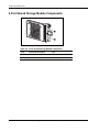
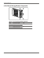
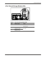
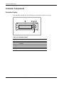
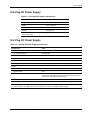
1
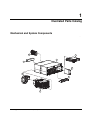
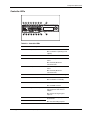
HP StorageWorks Modular Smart Array 500
System
Maintenance and Service Guide
(formerly Smart Array Cluster Storage System)
October 2003 (Fourth Edition)
Part Number 251850-004
© 2002, 2003 Hewlett-Packard Development Company, L.P.
Microsoft®, Windows®, and Windows NT® are trademarks of Microsoft Corporation in the U.S. and other
countries.
Hewlett-Packard Company shall not be liable for technical or editorial errors or omissions contained herein. The
information in this document is provided “as is” without warranty of any kind and is subject to change without
notice. The warranties for HP products are set forth in the express limited warranty statements accompanying such
products. Nothing herein should be construed as constituting an additional warranty.
HP StorageWorks Modular Smart Array 500 System Maintenance and Service Guide
October 2003 (Fourth Edition)
Part Number 251850-004
Contents
About This Guide
Audience Assumptions..................................................................................................................................v
Technician Notes...........................................................................................................................................v
Where to Go for Additional Help.................................................................................................................vi
Telephone Numbers ...............................................................................................................................vi
Chapter 1
Illustrated Parts Catalog
Mechanical and System Components........................................................................................................ 1-1
Chapter 2
Removal and Replacement Procedures
Safety Considerations................................................................................................................................ 2-1
Preventing Electrostatic Discharge ..................................................................................................... 2-1
Rack Warnings and Cautions.............................................................................................................. 2-2
Device Warnings and Cautions........................................................................................................... 2-2
Weight Warning.................................................................................................................................. 2-3
System Power Down ................................................................................................................................. 2-4
Hard Drive Blank ...................................................................................................................................... 2-4
Hot-Plug SCSI Hard Drive........................................................................................................................ 2-5
Universal Hot-Plug Tape Drive................................................................................................................. 2-7
Bezel Blank ............................................................................................................................................... 2-8
HP StorageWorks Modular Smart Array 500 Controller .......................................................................... 2-9
Battery-Backed Cache Module................................................................................................................ 2-10
Blower ..................................................................................................................................................... 2-11
Hot-Plug Power Supply........................................................................................................................... 2-12
2-Port and 4-Port Shared Storage Modules ............................................................................................. 2-14
Interconnect Blank .................................................................................................................................. 2-15
Power Button/LED Assembly ................................................................................................................. 2-16
MSA500 System Chassis and Backplane................................................................................................ 2-17
Chapter 3
Diagnostic Tools
Server Utilities........................................................................................................................................... 3-1
ROM Upgrades.......................................................................................................................................... 3-2
Array Diagnostics Utility .......................................................................................................................... 3-2
Array Configuration Utility....................................................................................................................... 3-2
NetWare Online Array Configuration Utility (CPQONLIN).................................................................... 3-3
HP StorageWorks Modular Smart Array 500 System Maintenance and Service Guide
iii
Contents
Chapter 4
Component Identification
Front Panel Components............................................................................................................................4-1
Enclosure LEDs .........................................................................................................................................4-2
Rear Panel Components.............................................................................................................................4-3
Power Supply/Blower Assembly LEDs.....................................................................................................4-3
2-Port Shared Storage Module Components..............................................................................................4-4
2-Port Shared Storage Module LEDs.........................................................................................................4-5
4-Port Shared Storage Module Components..............................................................................................4-6
4-Port Shared Storage Module LEDs.........................................................................................................4-7
Controller Components..............................................................................................................................4-8
Controller Display ...............................................................................................................................4-8
Controller LEDs ..................................................................................................................................4-9
SCSI IDs ..................................................................................................................................................4-11
Hot-Plug SCSI Hard Drive LEDs ............................................................................................................4-12
Hot-Plug SCSI Hard Drive LED Combinations ......................................................................................4-12
Chapter 5
Specifications
System Unit Specification..........................................................................................................................5-1
Memory......................................................................................................................................................5-2
2-Port and 4-Port Shared Storage Modules................................................................................................5-2
Hot-Plug AC Power Supply.......................................................................................................................5-3
Hot-Plug DC Power Supply.......................................................................................................................5-3
Index
iv
HP StorageWorks Modular Smart Array 500 System Maintenance and Service Guide
About This Guide
This maintenance and service guide can be used for reference when servicing the HP
StorageWorks Modular Smart Array 500 system.
WARNING: To reduce the risk of personal injury from electric shock and hazardous
energy levels, only authorized service technicians should attempt to repair this
equipment. Improper repairs can create conditions that are hazardous.
Audience Assumptions
This guide is for service technicians. HP assumes you are qualified in the servicing of
computer equipment and trained in recognizing hazard in products with hazardous energy
levels and are familiar with weight and stability precautions for rack installations.
Technician Notes
WARNING: Only authorized technicians trained by HP should attempt to repair this
equipment. All troubleshooting and repair procedures are detailed to allow only
subassembly/module-level repair. Because of the complexity of the individual boards
and subassemblies, no one should attempt to make repairs at the component level or
to make modifications to any printed wiring board. Improper repairs can create a safety
hazard.
WARNING: To reduce the risk of personal injury from electric shock and hazardous
energy levels, do not exceed the level of repairs specified in these procedures.
Because of the complexity of the individual boards and subassemblies, do not attempt
to make repairs at the component level or to make modifications to any printed wiring
board. Improper repairs can create conditions that are hazardous.
WARNING: To reduce the risk of electric shock or damage to the equipment:
•
Disconnect power from the system by unplugging all power cords from the power
supplies.
•
Do not disable the power cord grounding plug. The grounding plug is an important
safety feature.
•
Plug the power cord into a grounded (earthed) electrical outlet that is easily
accessible at all times.
HP StorageWorks Modular Smart Array 500 System Maintenance and Service Guide
v
About This Guide
CAUTION: To properly ventilate the system, you must provide at least 7.6 cm (3.0 in) of
clearance at the front and back of the system.
CAUTION: The equipment is designed to be electrically grounded (earthed). To ensure
proper operation, plug the AC power cord into a properly grounded AC outlet only.
NOTE: Any indications of component replacement or printed wiring board modifications may void any
warranty.
Where to Go for Additional Help
In addition to this guide, the following information sources are available:
•
HP StorageWorks Modular Smart Array 500 System User Guide
•
HP StorageWorks Modular Smart Array 500 System Hardware Configuration and
Installation Poster
•
HP StorageWorks Modular Smart Array 500 Controller Installation Instructions
•
HP DC Power Supply Option Installation Instructions
•
HP 4-Port Shared Storage Module Option Installation Instructions
•
Operating System and Drivers Manual Installation Guide
•
Documentation CD
•
Service Quick Reference Guide
•
Service training guides
•
Service advisories and bulletins
•
QuickFind information services
•
Insight Manager software
Telephone Numbers
For the name of the nearest HP authorized reseller:
•
In the United States, call 1-800-345-1518.
•
In Canada, call 1-800-263-5868.
For HP technical support:
•
In the United States and Canada, call 1-800-652-6672.
•
Outside the United States and Canada, refer to
www.hp.com
vi
HP StorageWorks Modular Smart Array 500 System Maintenance and Service Guide
1
Illustrated Parts Catalog
Mechanical and System Components
6
7
1
3
8
5
2
4
HP StorageWorks Modular Smart Array 500 System Maintenance and Service Guide
1-1
Illustrated Parts Catalog
Table 1-1: Mechanical and System Components
Item
Description
Spare Part Number
Mechanical Components
1
Chassis, 4U, with backplane
229198-001
2
Bezel blank
229208-001
3
Interconnect blank
229200-001
System Components
4
AC power supply assembly, 499 W
212398-001
5
Blower
123482-001
Boards
6
2-Port Shared Storage Module for HP StorageWorks Modular Smart Array 500
system
229205-001
7
Controller
229202-001
8
Power button/LED assembly
229201-001
9
Cache module, DIMM, SDRAM, 128 MB, with battery *
171387-001
Miscellaneous
10
AC power cord *
187335-001
11
Return kit *
249670-001
Options
12
4-Port Shared Storage Module for MSA500 system *
300867-001
13
DC power supply, -48 V *
243791-001
14
Cache module, DIMM, SDRAM, 256 MB, with battery *
262012-001
15
Universal hard drive, 1-inch *
177986-001
16
Universal Hot-Plug Tape drives *
17
a) AIT, 50/100-GB capacity
190716-001
b) AIT, 35/70-GB capacity
218575-002
c) DDS-4, 20/40-GB capacity
230203-001
M-Series Rack Rail option *
314635-001
* Not shown
1-2
HP StorageWorks Modular Smart Array 500 System Maintenance and Service Guide
2
Removal and Replacement Procedures
To service the MSA500 system, you may need the following tools:
•
Flat-blade screwdriver
•
From the SmartStart CD:
— Advanced Diagnostics Utility (ADU)
— ROM Update Utility
Safety Considerations
Before performing service procedures, review all the safety information.
Preventing Electrostatic Discharge
To prevent damaging the system, be aware of the precautions you need to follow when
setting up the system or handling parts. A discharge of static electricity from a finger or other
conductor may damage system boards or other static-sensitive devices. This type of damage
may reduce the life expectancy of the device.
To prevent electrostatic damage:
•
Avoid hand contact by transporting and storing products in static-safe containers.
•
Keep electrostatic-sensitive parts in their containers until they arrive at static-free
workstations.
•
Place parts on a grounded surface before removing them from their containers.
•
Avoid touching pins, leads, or circuitry.
•
Always be properly grounded when touching a static-sensitive component or assembly.
HP StorageWorks Modular Smart Array 500 System Maintenance and Service Guide
2-1
Removal and Replacement Procedures
Rack Warnings and Cautions
WARNING: Because the rack allows stacking of computer components on a vertical
rather than horizontal plane, be sure that precautions have been taken to provide for
rack stability and safety. It is important to follow these precautions providing for rack
stability and safety, and to protect both personnel and property. Heed all cautions and
warnings throughout the installation instructions provided with the device.
WARNING: To reduce the risk of personal injury or damage to the equipment:
•
Observe local occupational safety requirements and guidelines for heavy
equipment handling.
•
Obtain adequate assistance to lift and stabilize the product during installation or
removal.
•
Always load the heaviest item first, and load the rack from the bottom up. This
makes the rack bottom-heavy and helps prevent the rack from becoming unstable.
•
Extend the leveling jacks to the floor.
•
Rest the full weight of the rack on the leveling jacks.
•
Attach the stabilizing feet to the rack if it is a single-rack installation.
•
The racks are coupled together in multiple-rack installations.
•
Fully extend the bottom stabilizers on the equipment. Be sure that the equipment is
properly supported/braced when installing options and boards.
•
Be sure that the rack is adequately stabilized before extending a component
outside the rack. Extend only one component at a time. A rack may become
unstable if more than one component is extended for any reason.
•
Do not attempt to move a fully loaded equipment rack. Remove equipment from the
rack before moving the rack.
•
At least two people are needed to safely unload the rack from the pallet. An empty
42U rack weighs 115 kg (253 lb), is over 2.1m (7 ft) tall, and may become unstable
when being moved on its casters. Do not stand in front of the rack as it rolls down
the ramp from the pallet; handle it from the sides. Stabilize the device by keeping
the unit on the rails.
Device Warnings and Cautions
Before installing a system, be sure that you understand the following warnings and cautions.
WARNING: To reduce the risk of personal injury or damage to the equipment, observe
all warnings and cautions throughout this chapter.
WARNING: Do not exceed the level of repair specified in the procedures in the product
documentation. All troubleshooting and repair procedures are detailed to allow only
subassembly or module-level repair. Because of the complexity of the individual
boards and subassemblies, do not attempt to make repairs at the component level or to
make modifications to any printed wiring board. Improper repairs can create a safety
hazard.
2-2
HP StorageWorks Modular Smart Array 500 System Maintenance and Service Guide
Removal and Replacement Procedures
WARNING: Be sure that the AC power supply branch circuit that provides power to the
rack is not overloaded. Not overloading AC power to the rack power supply circuit
reduces the risk of personal injury, fire, or damage to the equipment. The total rack
load should not exceed 80 percent of the branch circuit rating. Consult the electrical
authority having jurisdiction over your facility wiring and installation requirements.
WARNING: To reduce the risk of personal injury or damage to the equipment, the
installation of options other than hot-plug power devices should be performed only by
individuals who are qualified in servicing computer equipment and trained to deal with
products capable of producing hazardous energy levels.
WARNING: To reduce the risk of electric shock or damage to the equipment:
•
Do not disable the power cord grounding plug. The grounding plug is an important
safety feature.
•
Plug the power cord into a grounded (earthed) electrical outlet that is easily
accessible at all times.
•
Unplug the power cord from the power supply to disconnect power to the
equipment.
•
Do not route the power cord where it can be walked on or pinched by items placed
against it. Pay particular attention to the plug, electrical outlet, and the point where
the cord extends from the system.
•
Do not use conductive tools that could bridge live parts.
•
Remove all watches, rings, or loose jewelry when working in hot-plug areas of an
energized device.
WARNING: To reduce the risk of personal injury from hot surfaces, allow the drives
and the internal system components to cool before touching them.
CAUTION: Protect the device from power fluctuations and temporary interruptions with a
regulating uninterruptible power supply (UPS). This device protects the hardware from
damage caused by power surges and voltage spikes, and keeps the system in operation
during a power failure.
Weight Warning
WARNING: The MSA500 system weighs 22.7 kg (50 lb) when assembled for
shipping. To reduce the risk of personal injury or damage to equipment:
22.7 kg
50 lb
•
Observe local health and safety requirements and guidelines for manual
material handling.
•
Obtain adequate assistance to lift and stabilize the MSA500 system during
installation or removal.
•
Remove all tape drives, if installed, to reduce the overall weight of the
system.
HP StorageWorks Modular Smart Array 500 System Maintenance and Service Guide
2-3
Removal and Replacement Procedures
System Power Down
WARNING: To reduce the risk of personal injury, electric shock, or damage to the
equipment, remove the power cord to remove power from the system. The front panel
Power On/Standby button does not completely shut off system power. Portions of the
power supply and some internal circuitry remain active until AC power is removed.
IMPORTANT: If installing a hot-plug device, it is not necessary to power down the system.
To power down the system:
1. Power down any attached servers. Refer to the server documentation.
2. Press the Power On/Standby button. Wait for the system power LED to go from green to
off.
3. Disconnect the power cords.
Hard Drive Blank
CAUTION: Always populate drive bays with either a hard drive or blank. Proper airflow can
only be maintained when the bays are populated. Operating the system with unpopulated
drive bays can lead to improper cooling and thermal damage.
To remove the component:
1
2
To replace a blank, slide the blank into the bay until it locks into place.
2-4
HP StorageWorks Modular Smart Array 500 System Maintenance and Service Guide
Removal and Replacement Procedures
Hot-Plug SCSI Hard Drive
CAUTION: If you must replace a hot-plug drive, follow the guidelines in this section. Failure
to do so can result in data loss and can void the warranty.
RAID 0 is not a fault-tolerant configuration. Never remove a drive from a RAID 0 array
unless it has failed. Drive failure is indicated by an amber drive failure LED. In a RAID 0
configuration, removal of an operating drive results in data loss. To remove a drive without
losing data, always back up the entire array, replace the drive, and restore the entire array.
Backing up a single drive and replacing it does not restore the array.
Some instances exist in which you may replace a drive in RAID 1, 5, and Advanced Data
Guarding configurations. To determine when drive replacement is possible without data loss,
use the hot-plug SCSI hard drive LEDs combination table in Chapter 4, “Component
Identification.”
Follow these additional guidelines when replacing drives:
•
Never remove more than one drive at a time (or two drives if you are using
Advanced Data Guarding). When you replace a drive, the controller uses data from the
other drives in the array to reconstruct data on the replacement drive. If you remove more
than one drive, a complete data set is not available to reconstruct data on the replacement
drive(s) and permanent data loss could occur.
•
Never remove a drive while the controller is rebuilding another drive. A drive’s
online LED flashes green while it is being rebuilt. The controller requires the data from
all other drives to rebuild the replacement drive.
•
If the system has an online spare drive, wait for it to complete rebuilding before
replacing the failed drive. When a drive fails, the online spare becomes active and
begins rebuilding as a replacement drive. After the online spare has completed Automatic
Data Recovery (the online LED is continuously lit), replace the failed drive with a new
replacement drive. Do not replace the failed drive with the online spare. The system
automatically rebuilds the replacement drive and resets the spare drive to an available
state.
•
If you replace a drive while the system is off, it may be necessary to rebuild the
replaced drive.
HP StorageWorks Modular Smart Array 500 System Maintenance and Service Guide
2-5
Removal and Replacement Procedures
To remove the component:
1. Be sure that the online and activity LEDs on the failed drive are both off.
CAUTION: To prevent improper cooling and thermal damage, do not operate the system
unless all bays are populated with either a component or a blank.
2. Remove the failed drive.
3
2
1
To replace a hot-plug SCSI hard drive:
1. Slide the drive into the bay until it locks into place.
2. Close the lever.
CAUTION: Data loss can occur if the drive is not firmly seated.
3. Be sure that the drive LEDs illuminate one at a time and then turn off together to indicate
that the system has recognized the new drive.
In fault-tolerant configurations, allow the replacement drive to be reconstructed
automatically with data from the other drives. While reconstruction is in progress, the
online LED flashes.
2-6
HP StorageWorks Modular Smart Array 500 System Maintenance and Service Guide
Removal and Replacement Procedures
Universal Hot-Plug Tape Drive
To remove the component:
CAUTION: To prevent improper cooling and thermal damage, do not operate the system
unless all bays are populated with either a component or a blank.
CAUTION: Installation of the tape drive height converter is permanent. Attempting to
remove the converter after installation voids the tape drive warranty.
1
2
To replace the Universal Hot-Plug Tape drive:
1. Install a new tape drive height converter on the replacement tape drive.
2. Slide the tape drive into the bay until it locks into place.
CAUTION: Data loss can occur if the drive is not firmly seated.
HP StorageWorks Modular Smart Array 500 System Maintenance and Service Guide
2-7
Removal and Replacement Procedures
Bezel Blank
To remove the component:
CAUTION: Always populate bays with either a component or blank. Proper airflow can only
be maintained when the bays are populated. Operating the system with unpopulated bays can
lead to improper cooling and thermal damage.
1
2
3
To replace the bezel blank:
1. Slide the bezel blank into the bay until it locks into place.
2. Close the lever.
2-8
HP StorageWorks Modular Smart Array 500 System Maintenance and Service Guide
Removal and Replacement Procedures
HP StorageWorks Modular Smart Array 500 Controller
When the MSA500 controller in a single-controller system fails, HP recommends that you
migrate the cache module to a new controller. Battery-backed cached data in a failed
controller can remain intact for up to 3 days with 256-MB modules or up to 4 days with
128-MB modules.
CAUTION: Failure to migrate the cache to a new controller and flush the data can result in
loss of the data that is written in the cache but was unable to be written to the hard drives
before controller failure.
To remove the component:
2
1
To restore the data:
1. Remove the cache modules from the failed controller. Refer to “Battery-Backed Cache
Module” in this chapter.
2. Install the cache modules in the new controller.
3. Install the new controller and allow the cache to write the stored data.
To replace the controller:
1. Slide the controller into the bay until it locks into place.
2. Close the lever.
3. Verify that the controller is seated properly by observing the controller LEDs. When
seated properly, the LEDs illuminate when the system is powered.
HP StorageWorks Modular Smart Array 500 System Maintenance and Service Guide
2-9
Removal and Replacement Procedures
Battery-Backed Cache Module
CAUTION: To prevent data loss or equipment damage, follow the instructions in this
procedure.
To remove the component:
1. Determine if the controller configuration supports hot-plug cache replacement:
— If the system is equipped with a single controller, power down the system before
performing step 2. Refer to “System Power Down” in this chapter.
— If the system has redundant controllers and the replacement cache is a different
capacity than the failed cache, power down the system before performing step 2.
— If the system has redundant controllers and the replacement cache is the same
capacity as the failed cache, proceed with step 2.
2. Remove the controller. Refer to “HP StorageWorks Modular Smart Array 500
Controller” in this chapter.
3. Remove the cache module.
2
1
3
4
4. Repeat steps 2 and 3 if the system has redundant controllers and the replacement cache is
a different capacity than the failed cache.
To replace the cache module:
1. Install the module in the slot.
2. Close the slot latches.
3. Close the controller.
2-10
HP StorageWorks Modular Smart Array 500 System Maintenance and Service Guide
Removal and Replacement Procedures
Blower
To remove the component:
WARNING: The blower blades rotate at a high speed. Avoid touching the rotating
blades when removing the blower.
NOTE: The power supply is designed so that removing a blower does not adversely affect system
performance. However, do not remove a blower until the replacement blower is available.
1
2
1
To replace the blower:
1. Align the guidepost on the blower with the connector on the power supply.
CAUTION: Do not press on the center section of the blower because this action can
damage the blades. Press only on the outer edge of the blower.
2. Slide the blower into the connector until it locks into place.
3. Be sure the following conditions occur:
— The blower begins operating immediately.
— The power supply/blower assembly LED is green.
HP StorageWorks Modular Smart Array 500 System Maintenance and Service Guide
2-11
Removal and Replacement Procedures
Hot-Plug Power Supply
Observe the following cautions for AC power supplies:
CAUTION: Removing a power supply significantly changes the airflow within the enclosure.
The system will shut down to prevent overheating unless the power supply is replaced within
5 minutes.
CAUTION: Handle the blower carefully to avoid damaging the housing.
•
Do not press on the center section of the blower because this action can damage the
blades. Press only on the outer edge of the blower.
•
Do not rest the power supply on the blower because the weight of the power supply can
damage the blower housing.
Observe these additional warnings and cautions for DC power supplies:
WARNING: A risk of personal injury from electric shock and hazardous energy levels
exists. The installation of options and routine maintenance and service of this product
must be performed by individuals who are knowledgeable about the procedures,
precautions, and hazards associated with DC power products.
WARNING: To reduce the risk of electric shock, fire, and damage to the equipment,
this product must be installed in accordance with the following guidelines:
•
This power supply is intended only for installation in HP equipment located in a
restricted access location.
•
This power supply is not intended for direct connection to the DC supply branch
circuit. It should be connected to a power distribution unit (PDU) that provides an
independent overcurrent-protected output for each DC power supply. Each output
overcurrent-protected device in the PDU must be suitable for interrupting fault
current available from the DC power source and must be rated no more than 20A.
•
This power supply is designed to be connected only to a DC power source that can
be classified as SELV or TNV, in accordance with applicable national requirements
for Information Technology Equipment and Telecommunications Equipment.
Generally, these requirements are based on the International Standard for
Information Technology Equipment, IEC 60950, and/or the European
Telecommunication Standard ETC 300 132-2. The DC source is to have one pole
(Neutral/Return) reliably connected to earth ground in accordance with
local/regional electric codes and/or regulations.
•
The green/yellow cable of the power cord assembly must be connected to a
suitable ground/earth terminal located within the rack or cabinet. This terminal
must be connected to a suitable building ground/earth terminal in accordance with
local/regional electric codes/regulations. Do not rely on the rack or cabinet chassis
to provide adequate ground/earth continuity.
CAUTION: Do not operate the storage system with one AC power supply and one DC power
supply installed.
2-12
HP StorageWorks Modular Smart Array 500 System Maintenance and Service Guide
Removal and Replacement Procedures
To remove the component:
1. Disconnect the power cord from the power supply.
2. Remove the blower. Refer to “Blower” in this chapter.
3. Remove the power supply.
1
2
To replace the power supply:
1. Lift the locking latch.
2. Slide the power supply into the bay until it locks into place.
3. Install the blower on the power supply.
4. Connect the power cord.
If you are replacing AC power supplies with DC power supplies, refer to the DC Power
Supply Option Installation Instructions that ship with the option.
HP StorageWorks Modular Smart Array 500 System Maintenance and Service Guide
2-13
Removal and Replacement Procedures
2-Port and 4-Port Shared Storage Modules
To remove the component:
1. Power down the system. Refer to “System Power Down” in this chapter.
2. Disconnect the SCSI cabling connected to the 2-Port Ultra3 SCSI I/O module.
3. Remove the module.
1
2
To replace the component, reverse the removal procedure.
If you are replacing a failed 2-Port Shared Storage Module with a 4-Port Shared Storage
Module, refer to the 4-Port Shared Storage Module Installation Instructions that ship with
the option.
2-14
HP StorageWorks Modular Smart Array 500 System Maintenance and Service Guide
Removal and Replacement Procedures
Interconnect Blank
To remove the component:
CAUTION: Always populate interconnect bays with a blank. Proper airflow can only be
maintained when the bays are populated. Operating the system with unpopulated bays can
lead to improper cooling and thermal damage.
1
2
To replace the component, reverse the removal procedure.
HP StorageWorks Modular Smart Array 500 System Maintenance and Service Guide
2-15
Removal and Replacement Procedures
Power Button/LED Assembly
To remove the component:
1. Power down the system. Refer to “System Power Down” in this chapter.
2. Remove the hot-plug SCSI hard drives in bays 10 through 14. Refer to “Hot-Plug SCSI
Hard Drive” in this chapter.
IMPORTANT: To press the plastic latches behind the front bezel, you may choose to use a
flat-head screwdriver.
3. Remove the power button/LED assembly:
1
2
1
To replace the component, slide the power button/LED assembly into the bay until it locks
into place.
2-16
HP StorageWorks Modular Smart Array 500 System Maintenance and Service Guide
Removal and Replacement Procedures
MSA500 System Chassis and Backplane
If the backplane board fails or the chassis sustains significant damage, you must order a
replacement chassis.
To replace the chassis and backplane:
1. Power down the system. Refer to “System Power Down” in this chapter.
2. Remove all installed hard drive blanks. Refer to “Hard Drive Blank” in this chapter.
3. Remove all installed hot-plug SCSI hard drives. Refer to “Hot-Plug SCSI Hard Drive” in
this chapter.
4. Remove the Universal Hot-Plug Tape drive, if installed. Refer to “Universal Hot-Plug
Tape Drive” in this chapter.
5. Remove the bezel blank. Refer to “Bezel Blank” in this chapter.
6. Remove the controllers. Refer to “HP StorageWorks Modular Smart Array 500
Controller” in this chapter.
7. Remove the power supplies. Refer to “Hot-Plug Power Supply” in this chapter.
8. Remove the 2-Port or 4-Port Shared Storage module. Refer to “2-Port and 4-Port Shared
Storage Modules” in this chapter.
9. Remove the interconnect blanks. Refer to “Interconnect Blank” in this chapter.
10. Remove the power button/LED assembly. Refer to “Power Button/LED Assembly” in
this chapter.
11. Handwrite the serial number of the original chassis on the label on the replacement
chassis, shown in the following figure.
IMPORTANT: Always keep the serial number of the original chassis for warranty validation
purposes.
12. Install all the removed components in the new chassis. To replace each component, refer
to the procedures in this chapter.
HP StorageWorks Modular Smart Array 500 System Maintenance and Service Guide
2-17
3
Diagnostic Tools
Server Utilities
HP utilities provide reporting functions that enable event-focused management and
diagnostics. To install and run these utilities, refer to the server documentation.
•
Diagnostics Utility—This utility tests and verifies proper operation of the system
hardware. If problems are found, the utility isolates failure(s) down to the replaceable
part, whenever possible. When an operating system is installed with SmartStart
Version 5.30 or later, the Diagnostics and utilities are installed on a partition of the hard
drive that contains the operating system. (This hard drive may or may not be located in
the storage system.) Always access these utilities when a system configuration error is
detected during POST.
•
INSPECT Utility—This utility provides a report detailing system information.
•
Insight Manager 7—This Web-based application enables system administrators to
accomplish normal administrative tasks from any remote location, using a Web browser.
Insight Manager 7 provides device management capabilities that consolidate and
integrate management data from HP and third-party devices.
•
Insight Management Agents—These agents enable easy manageability of the server
through Insight Manager 7 software and third-party SNMP management platforms.
Management agents monitor key subsystems that are instrumental in making health,
configuration, and performance data available to the agent software. The agents act upon
that data by initiating alarms in the event of faults. The agents also provide updated
management information, such as network interface or subsystem performance statistics,
to the management systems.
•
Survey Utility—This utility gathers critical hardware and software information on
servers running Microsoft® Windows® and Novell NetWare operating systems. If a
significant change occurs between data-gathering intervals, the Survey Utility marks the
previous information and overwrites the Survey text files to reflect the latest changes in
the configuration.
HP StorageWorks Modular Smart Array 500 System Maintenance and Service Guide
3-1
Diagnostic Tools
ROM Upgrades
Each MSA500 controller has a ROM that contains the controller firmware.
The ROM flash tool enables system administrators to efficiently upgrade array controller
ROM images. This tool has the following features:
•
Supports Microsoft Windows NT® 4.0, Windows 2000, Novell NetWare (offline only),
and Linux operating systems
•
Integrates with other software maintenance, deployment, and operating system tools
•
Automatically checks for hardware, firmware, and operating system dependencies, and
installs only the correct ROM upgrades required by each target controller
For firmware procedures, refer to the SmartStart CD.
Array Diagnostics Utility
ADU collects all possible information about the array controllers in the system and generates
a list of detected problems. You can save this data to a file for analysis. In most cases, ADU
provides sufficient information for troubleshooting procedures.
To obtain ADU, download the utility from the HP website:
www.hp.com
Array Configuration Utility
ACU Version 6.0 (or later) is a browser-based utility with the following features:
•
Supports online array capacity expansion, logical drive capacity extension, assignment of
online spares, and RAID or stripe size migration
•
Suggests the optimum configuration for an unconfigured system
•
Provides different operating modes, enabling faster configuration or greater control over
the configuration options
•
Remains available any time that the server is on
•
Displays on-screen tips for individual steps of a configuration procedure
The minimum display settings for optimum performance are 800 × 600 resolution and 256
colors. The server must have Microsoft Internet Explorer 5.5 (with Service Pack 1) installed
and be running Microsoft Windows 2000, Windows NT 4.0, or Linux. Refer to the
README.TXT file for further information about browser and Linux support.
For more information about ACU Version 6.0 (or later), refer to the HP Array Configuration
Utility User Guide on the Documentation CD.
3-2
HP StorageWorks Modular Smart Array 500 System Maintenance and Service Guide
Diagnostic Tools
NetWare Online Array Configuration Utility (CPQONLIN)
The NetWare Online Array Configuration Utility, also called CPQONLIN, is a NetWare
Loadable Module (NLM) for configuring drive arrays without shutting down the server.
CPQONLIN also provides information about the status of drives attached to the MSA500
controller. It indicates drive failure, expansion, or waiting for expansion or rebuild (queued).
For more NetWare Online Array Configuration Utility information, refer to the HP
StorageWorks Modular Smart Array 500 System User Guide or the HP Array Configuration
Utility User Guide on the Documentation CD.
HP StorageWorks Modular Smart Array 500 System Maintenance and Service Guide
3-3
4
Component Identification
Front Panel Components
1
2
3
7
4
6
5
Table 4-1: Front Panel Components
Item
Description
1
Bezel blank (bay for optional redundant controller)
2
Service port (for HP service technicians only)
3
Hot-plug MSA500 controller
4
Controller display
5
Power On/Standby button
6
Enclosure LEDs (refer to Table 4-2)
7
Hot-plug SCSI hard drive bays with blanks
HP StorageWorks Modular Smart Array 500 System Maintenance and Service Guide
4-1
Component Identification
Enclosure LEDs
1
2
3
Table 4-2: Enclosure LEDs
Item
LED Description
Status
1
Environmental
Monitoring Unit
(EMU) heartbeat
Green flashing = Shared storage module is
operating normally.
System power
Green = System power is On.
2
Green/Off = Shared storage module is not
operating normally.
Off = System is in standby mode or power
is removed from the system.
3
Fault
Amber = Fault detected in a subsystem
Off = No faults detected
IMPORTANT: The Power On/Standby button does not remove all power from the system. The Standby
mode removes power from most of the electronics and the drives, but portions of the power supply and
some internal circuitry remain active. To remove power completely, disconnect all power cords from the
equipment.
4-2
HP StorageWorks Modular Smart Array 500 System Maintenance and Service Guide
Component Identification
Rear Panel Components
1
2
3
4
Table 4-3: Rear Panel Components
Item
Description
1
Interconnect blanks (Required for proper airflow)
2
Power supply/blower assemblies
3
AC power connectors
4
2-Port Shared Storage Module
Power Supply/Blower Assembly LEDs
The power supply/blower assembly LEDs have the following functions:
•
Green—The power supply is receiving power, and the blower is operating normally.
•
Off—No power is present; the power supply or the blower has failed.
HP StorageWorks Modular Smart Array 500 System Maintenance and Service Guide
4-3
Component Identification
2-Port Shared Storage Module Components
1
2
Table 4-4: 2-Port Shared Storage Module Components
4-4
Item
Connector Description
Bus
1
SCSI port connector
A
2
SCSI port connector
B
HP StorageWorks Modular Smart Array 500 System Maintenance and Service Guide
Component Identification
2-Port Shared Storage Module LEDs
1
2
3
Table 4-5: 2-Port Shared Storage Module LEDs
Item
LED Description
Status
1
Power
Green = Power on
Off = Power off
2
SCSI host port A
Flashing green = On/Activity
3
SCSI host port B
Off = Off
HP StorageWorks Modular Smart Array 500 System Maintenance and Service Guide
4-5
Component Identification
4-Port Shared Storage Module Components
1
2
3
4
Table 4-6: 4-Port Shared Storage Module Components
4-6
Item
Connector Description
Bus
1
SCSI port connector A1
A
2
SCSI port connector A2
3
SCSI port connector B1
4
SCSI port connector B2
B
HP StorageWorks Modular Smart Array 500 System Maintenance and Service Guide
Component Identification
4-Port Shared Storage Module LEDs
1
2
3
Table 4-7: 4-Port Shared Storage Module LEDs
Item
LED Description
Status
1
Power
Green = Power on
Off = Power off
2
SCSI host port A
connectors 1 and 2
3
SCSI host port B
connectors 1 and 2
Flashing green = On/Activity
Off = Off
HP StorageWorks Modular Smart Array 500 System Maintenance and Service Guide
4-7
Component Identification
Controller Components
Controller Display
Each MSA500 controller has an LCD display for informational and error messages.
1
2
3
4
5
Table 4-8: Controller Display
4-8
Item
Description
1
Display
2
Left button
3
Up button
4
Right button
5
Down button
HP StorageWorks Modular Smart Array 500 System Maintenance and Service Guide
Component Identification
Controller LEDs
15
14
13
12
11
10
9
8
17
7
6
5
4
3
2
1
0
16
Table 4-9: Controller LEDs
Item
LED Description
Status
0-2
Busy status
Green = Controller is idle.
Off = Controller is operating at full
capacity.
3-5
No function
—
6
Host port A notification
Green = Notify On Event command
active
Off = No Notify On Event
command active
7
Host port B notification
Green = Notify On Event command
active
Off = No Notify On Event
command active
8
Idle heartbeat
Controller is idle and functioning.
9
Active/Standby
Green = Controller is active.
Off = Controller is in standby.
10
DMA activity
Green = DMA transfers are active.
Off = No DMA transfers.
11
Logical I/O activity
Green = Currently processing
logical requests from the host
adapter.
Off = No processing of logical
requests
12
SCSI bus 0 activity
13
SCSI bus 1 activity
Green = Outstanding requests on
the SCSI bus
Off = No outstanding requests
continued
HP StorageWorks Modular Smart Array 500 System Maintenance and Service Guide
4-9
Component Identification
Table 4-9: Controller LEDs continued
Item
LED Description
Status
14
Cache activity
Green = Cache activity
Off = No cache activity
Flashing green = Cache transfer
pending
15
Drive failure
Green = An array-configured drive
has failed.
Off = No drive failures
16
Active redundancy
Green = Controllers are operating
with redundancy.
Off = No redundancy
17
Fault
Amber = Error message received
by controller display.
Off = No error message received
or no error message currently
displayed.
4-10
HP StorageWorks Modular Smart Array 500 System Maintenance and Service Guide
Component Identification
SCSI IDs
1
2
3
4
5
6
7
8
9
10 11 12 13 14
Table 4-10: SCSI IDs
Bay
SCSI ID
Bus Port
1
0
0
2
1
3
2
4
3
5
4
6
5
7
8
8
0
9
1
10
2
11
3
12
4
13
5
14
8
1
HP StorageWorks Modular Smart Array 500 System Maintenance and Service Guide
4-11
Component Identification
Hot-Plug SCSI Hard Drive LEDs
1
3
2
Table 4-11: Hot-Plug SCSI Hard Drive LEDs
Item
LED Description
1
Activity
2
Online
3
Fault
Hot-Plug SCSI Hard Drive LED Combinations
Table 4-12: Hot-Plug SCSI Hard Drive LED Combinations
Activity LED
Online LED
Fault LED
Status
On
Flashing
Off
Do not remove the drive. Removing a drive during this process
can cause data loss in non-fault-tolerant configurations
Off
Off
On
•
The drive is a replacement drive and is being rebuilt or
•
If all online LEDs in a drive array are flashing, an expansion is
occurring.
OK to replace the drive online.
The drive has failed and has been placed offline.
Off, on, or
flashing
On
Off
Do not remove the drive. Removing a drive during this process
can cause data loss in non-fault-tolerant configurations.
The drive is online and configured as part of an array.
Off, on, or
flashing
4-12
On or Off
Flashing
A predictive failure alert has been received for this drive. Replace the
drive as soon as possible.
HP StorageWorks Modular Smart Array 500 System Maintenance and Service Guide
5
Specifications
System Unit Specification
Table 5-1: System Unit Specifications
Specification
Value
Dimensions
Height
17.5 cm (6.9 in)
Depth
52.1 cm (20.5 in)
Width
48.3 cm (19.0 in)
Weight, no drives installed
22.7 kg (50 lb)
Input power requirements * (US and international)
Rated input voltage
100 to 240 VAC
Rated input frequency
50 to 60 Hz
Rated input current
7.35 A Max
Input power (max)
641 W *
Power supply specifications
Rated steady-state power
499 W
Maximum peak power
681 W
Heat dissipation (max) *
2187 Btu/hr *
Acoustic noise (LWAdc bels and LpAm dBA)
Idle
<6.9 and 53
Fixed disk (random writes)
<7.3 and 54
Temperature range
Operating
10° to 35° C (50° to 95° F)
[derated 1°C per 304.8 m (1.8°F per 1000 ft) of
elevation to 3,048 m (10,000 ft)]
Shipping
-30° to 50° C (-22° to 122° F)
* Input power and heat dissipation specifications are maximum values and apply to worst-case
conditions at a full-rated power supply load. The power/heat dissipation for your installation varies
depending on the equipment configuration.
continued
HP StorageWorks Modular Smart Array 500 System Maintenance and Service Guide
5-1
Specifications
Table 5-1: System Unit Specifications continued
Specification
Value
Relative humidity (noncondensing)
Operating
10% to 90%
Nonoperating
up to 95%
Maximum wet bulb temperature
Long-term storage
29°C (84.2°F)
Short term storage
30°C (86°F)
Memory
Table 5-2: SDRAM DIMM Specifications
Specification
Value
Speed
100 MHz minimum
Width
80 bits
Note: Use only HP battery-backed cache modules.
2-Port and 4-Port Shared Storage Modules
Table 5-3: 2-Port and 4-Port Shared Storage Module
Specifications
5-2
Specification
Value
Height
11.4 cm (4.5 in)
Width
3.5 cm (1.38 in)
Depth
24.1 cm (9.5 in)
Weight
0.6 kg (1.3 lb)
HP StorageWorks Modular Smart Array 500 System Maintenance and Service Guide
Specifications
Hot-Plug AC Power Supply
Table 5-4: Hot-Plug Power Supply Specifications
Specification
Value
Height
12.7 cm (4.5 in)
Width
15.9 cm (6.25 in)
Depth
24.1 cm (9.5 in)
Weight
2.9 kg (6.4 lb)
Note: The MSA500 system power supply specifications are calculated
without the blower.
Hot-Plug DC Power Supply
Table 5-5: Hot-Plug DC Power Supply Specifications
Specification
Value
Voltage
Nominal input voltage
-48 or 48 VDC
Maximum input voltage
75 VDC
Operating voltage range
36 to 72 VDC
Ripple/Noise
100 mV PARD*
Overshoot
Must remain within regulation limits during startup or shutdown
Current
Max steady state input current
13.2 A
In-rush current
70 A
Input over-current
Customer must provide fusing for facility DC feeds that protect the
system from catastrophic over-current within 20 uS. Fuse should
sustain all in-rush and operating currents.
Max input current slew rate
1A/uS
Max rated power
499 W
*Periodic and random noise (PARD). Maximum allowable peak-to-peak ripple and noise (as measured at the load on
any output channel). The ripple and noise is measured over a 20 Hz to 100 MHz frequency band.
HP StorageWorks Modular Smart Array 500 System Maintenance and Service Guide
5-3
Index
Symbols and Numbers
2-Port Shared Storage Module
components 4-4
LEDs 4-5
location 4-3
removing 2-14
replacing 2-14
spare part number 1-2
4-Port Shared Storage Module
components 4-6
LEDs 4-7
removing 2-14
replacing 2-14
spare part number 1-2
A
AC power connectors 4-3
AC power cord, spare part number 1-2
ADU See Array Diagnostics Utility (ADU)
Array Configuration Utility (ACU)
features 3-2
version 3-2
array controllers
LEDs 4-9
MSA500 4-1
removing 2-9
replacing 2-9
spare part number 1-2
Array Diagnostics Utility (ADU) 3-2
B
backplane
removing 2-17
replacing 2-17
battery-backed cache module
removing 2-10
replacing 2-10
spare part number 1-2
bays, SCSI hard drive 4-1
bezel blank
location 4-1
removing 2-8
replacing 2-8
spare part number 1-2
blowers
LEDs 4-3
location 4-3
removing 2-11
replacing 2-11
spare part number 1-2
C
cache module See battery-backed cache module
CDs
Documentation 3-2
SmartStart 3-2
chassis
replacing 2-17
spare part number 1-2
component-level repairs v
components
2-Port Shared Storage Module 4-4
4-Port Shared Storage Module 4-6
controller display 4-8
front panel 4-1
mechanical and system 1-2
rear panel 4-3
repairs, warning 2-2
configuring arrays 3-2
connectors
AC power 4-3
SCSI ports 4-4, 4-6
controller See array controllers
controller display
components 4-8
location 4-1
D
Diagnostic Utility 3-1
display 4-1, 4-8
Documentation CD 3-2
drive activity LED 4-12
drive bays 4-1
drive online LED 4-12
HP StorageWorks Modular Smart Array 500 System Maintenance and Service Guide
Index-1
Index
drives See hot-plug SCSI hard drives; tape drives
fault 4-10, 4-12
fault, enclosure 4-2
hot-plug SCSI hard drives 4-12
power supply/blower assembly 4-3
system power 4-2
E
EMU heartbeat LED 4-2
enclosure LEDs 4-1, 4-2
M
F
G
mechanical components 1-2
modules See 2-Port Shared Storage Module; 4-Port
Shared Storage Module; battery-backed cache
module
M-Series Rack Rail option, spare part number 1-2
grounding vi
grounding plug v
P
fault LEDs 4-2, 4-10, 4-12
front panel components 4-1
ports
H
hard drive blank
removing 2-4
replacing 2-4
hard drives See hot-plug SCSI hard drives
help resources vi
hot-plug SCSI hard drives
bays 4-1
LED combinations 4-12
LEDs 4-12
removing 2-6
replacement guidelines 2-5
replacing 2-6
SCSI IDs 4-11
spare part number 1-2
HP authorized reseller vi
R
I
Insight Management Agents 3-1
Insight Manager 7 3-1
INSPECT Utility 3-1
interconnect blanks
location 4-3
removing 2-15
replacing 2-15
spare part number 1-2
L
LEDs
2-Port Shared Storage Module 4-5
4-Port Shared Storage Module 4-7
combinations 4-12
controller 4-9
drive activity 4-12
drive online 4-12
EMU heartbeat 4-2
enclosure 4-1, 4-2
Index-2
LEDs 4-5, 4-7
service 4-1
power button/LED assembly
removing 2-16
replacing 2-16
spare part number 1-2
power fluctuations, caution 2-3
Power On/Standby button 2-4, 4-1
power supplies
LEDs 4-3
location 4-3
removing 2-13
replacing 2-13
spare part number 1-2
power supply/blower assembly See blowers; power
supplies
rack warnings 2-2
rear panel components 4-3
removing
2-Port Shared Storage Module 2-14
4-Port Shared Storage Module 2-14
array controllers 2-9
backplane 2-17
battery-backed cache module 2-10
bezel blank 2-8
blower 2-11
hard drive blank 2-4
hot-plug SCSI hard drives 2-6
interconnect blank 2-15
power button/LED assembly 2-16
power supplies 2-13
tape drives 2-7
replacing
2-Port Shared Storage Module 2-14
4-Port Shared Storage Module 2-14
array controllers 2-9
HP StorageWorks Modular Smart Array 500 System Maintenance and Service Guide
Index
backplane 2-17
battery-backed cache module 2-10
bezel blank 2-8
blower 2-11
chassis 2-17
hard drive blank 2-4
hot-plug SCSI hard drives 2-6
interconnect blank 2-15
power button/LED assembly 2-16
power supplies 2-13
tape drives 2-7
restoring data 2-9
return kit, spare part number 1-2
S
SCSI IDs 4-11
service port 4-1
shared storage modules See 2-Port Shared Storage
Module; 4-Port Shared Storage Module
SmartStart CD 2-1, 3-2
spare part numbers
2-Port Shared Storage Module 1-2
4-Port Shared Storage Module 1-2
AC power cord 1-2
array controller 1-2
battery-backed cache module 1-2
bezel blank 1-2
blower 1-2
chassis 1-2
hot-plug SCSI hard drives 1-2
interconnect blank 1-2
M-Series Rack Rail option 1-2
power button/LED assembly 1-2
power supplies 1-2
return kit 1-2
tape drives 1-2
Survey Utility 3-1
system components 1-2
system power LED 4-2
T
tape drives
removing 2-7
replacing 2-7
spare part number 1-2
technician notes v
telephone numbers vi
tools
required for servicing 2-1
software 2-1
U
UPS, caution 2-3
utilities
ADU 3-2
array configuration 3-2
Diagnostic 3-1
INSPECT 3-1
Survey 3-1
V
ventilation clearances vi
W
warranty vi
weight, warning 2-3
HP StorageWorks Modular Smart Array 500 System Maintenance and Service Guide
Index-3