1
SINUMERIK 840C
SINUMERIK 880/880 GA2
PLC 135 WB/WB2/WD
Planning Guide
Manufacturer Documentation
12.93 Edition
SINUMERIK 840C
SINUMERIK 880/880 GA2
PLC 135 WB/WB2/WD
Planning Guide
Manufacturer Documentation
Applies to:
Control
SINUMERIK 840C/CE
SINUMERIK 880 T/M
SINUMERIK 880 N
SINUMERIK 880 G
SINUMERIK 880 GA2 T/M
12.93 Edition
Software version
1, 2 and 3
3, 4, 6
4
2
1
SINUMERIK® documentation
Printing history
Brief details of this edition and previous editions are listed below.
The status of each edition is shown by the code in the ”Remarks” column.
Status code in ”Remarks” column:
A . . . New documentation
B . . . Unrevised reprint with new Order No.
C . . . Revised edition with new status.
If factual changes have been made on the page since the last edition, this is
indicated by a new edition coding in the header on that page.
Edition
Order No.
Remarks
03.90
6ZB5 410-0FC02-0BA0
A
03.91
6ZB5 410-0FC02-0AA1
C
06.92
6ZB5 410-0FC02-0AA2
C
11.92
6FC5197-0AA80-1BP0
A (replaces 6ZB5
410-0FC02-0AA2)
12.93
6FC5197-3AA80-0BP0
C
Other functions not described in this documentation might be
executable in the control. This does not, however, represent an
obligation to supply such functions with a new control or when
servicing.
This publication was produced on
System.
Subject to change without prior notice.
the
Siemens
5800
Office
The reproduction, transmission or use of this document or its
contents is not permitted without express written authority.
Offenders will be liable for damages. All rights, including rights
created by patent grant or registration of a utility model or
design, are reserved.
©
Siemens AG 1990, 1991, 1992, 1993 All Rights Reserved
Preliminary Remarks
Notes for the reader
This manual is intended for the manufacturers of machine tools using SINUMERIK 840C, 880
or 880 GA2.
With every new software version, certain functions, conditions, modules etc. are either no
longer possible or are added. Parts of this documentation affected by such changes are
marked by the following footnotes.
The Guide describes in detail the program structure and the operation set of the PLC.
The SINUMERIK documentation is organized in four parts:
•
•
•
•
General documentation
User documentation
Manufacturer documentation and
Service documentation
The Manufacturer Documentation for the SINUMERIK 840C and SINUMERIK 880 controls
is divided into the following:
•
•
•
•
•
•
Loose-leaf Sheets/Instruction Manual
Interface Guide
– Part 1: Signals
– Part 2: Connection Conditions
Function Macros
Function Blocks
– Package 0:
Basic Functions
– Package 1/2: Tool Management
– Package 4/5: Computer Link
– Package 6:
Loading and Unloading Tools with Code Carriers
– Package 7:
Code Carriers
– Package 8:
PLC-controlled Data Input/Output
PLC 135 WB/WB2/WD Planning Guide
S5-HLL High-Level Language Programming
Additional SINUMERIK publications are also available for all SINUMERIK controllers
(e.g. publications on the Measuring Cycles, CL800 Cycles language).
Please contact your Siemens regional office for further details.
•
The PLC 135 WB is used with SINUMERIK 880 and 880 GA2.
•
•
The PLC 135 WB2 is used with SINUMERIK 840C.
The PLC 135 WD is used with SINUMERIK 840C, SW 3 and higher.
aaaaaaaaaaaaaaaaaaaaaaaaaaaaaaaaaaaaaaaaaa
aaaaaaaaaaaaaaaaaaaaaaaaaaaaaaaaaaaaaaaaaa
aaaaaaaaaaaaaaaaaaaaaaaaaaaaaaaaaaaaaaaaaa
aaaaaaaaaaaaaaaaaaaaaa
aaaaaaaaaaa
aaaaaaaaaaaaaaaaaaaaaaaaaaaaaaaaaaaaaaaaaaaaaaaaaaaaa
aaaaaaaaaaaaaaaaaaaaaaaaaaaaaaaaaaaaaaaaaa
aaaaaaaaaaaaaaaaaaaaaaaaaaaaaaaaaaaaaaaaaa
aaaaaaaaaaaaaaaaaaaaa
Technical comments
Contents
Page
1
Introductory Remarks . . . . . . . . . . . . . . . . . . . . . . . . . . . . . . . . . . .
1–1
1.1
1.2
1.2.1
1.2.2
1.3
1.3.1
1.3.2
1.3.3
1.4
Application . . . . . . . . . . . . . . . . . . . . . . . . . . . . . . . . . . . . . . . . . . . .
Programming languages . . . . . . . . . . . . . . . . . . . . . . . . . . . . . . . . . .
STEP 5 programming language . . . . . . . . . . . . . . . . . . . . . . . . . . . . .
High-level language programming . . . . . . . . . . . . . . . . . . . . . . . . . . .
Programming . . . . . . . . . . . . . . . . . . . . . . . . . . . . . . . . . . . . . . . . . .
Program structure . . . . . . . . . . . . . . . . . . . . . . . . . . . . . . . . . . . . . .
Program organization . . . . . . . . . . . . . . . . . . . . . . . . . . . . . . . . . . . .
Program processing . . . . . . . . . . . . . . . . . . . . . . . . . . . . . . . . . . . . .
Differences between the PLC 135 WB2 and the PLC 135 WD
.......
1–1
1–1
1–1
1–2
1–2
1–2
1–3
1–4
1–6
2
Program Blocks
2–1
2.1
2.2
Programming program blocks . . . . . . . . . . . . . . . . . . . . . . . . . . . . . .
Calling program blocks . . . . . . . . . . . . . . . . . . . . . . . . . . . . . . . . . . .
2–1
2–2
3
Data Blocks
3–1
3.1
3.2
3.3
Programming data blocks . . . . . . . . . . . . . . . . . . . . . . . . . . . . . . . . .
Calling data blocks . . . . . . . . . . . . . . . . . . . . . . . . . . . . . . . . . . . . . .
Processing data words greater than data word 255 . . . . . . . . . . . . . . .
3–1
3–2
3–4
4
Function Blocks . . . . . . . . . . . . . . . . . . . . . . . . . . . . . . . . . . . . . . .
4–1
4.1
4.2
4.2.1
4.2.2
4.3
4.3.1
4.3.2
4.4
4.4.1
4.4.2
4.4.3
4.4.4
4.4.5
General remarks . . . . . . . . . . . . . . . . . . . . . . . . . . . . . . . . . . . . . . .
Structure of function blocks . . . . . . . . . . . . . . . . . . . . . . . . . . . . . . . .
Block header . . . . . . . . . . . . . . . . . . . . . . . . . . . . . . . . . . . . . . . . . .
Block body . . . . . . . . . . . . . . . . . . . . . . . . . . . . . . . . . . . . . . . . . . .
Calling and initializing function blocks . . . . . . . . . . . . . . . . . . . . . . . . .
Call statement . . . . . . . . . . . . . . . . . . . . . . . . . . . . . . . . . . . . . . . . .
Parameter list . . . . . . . . . . . . . . . . . . . . . . . . . . . . . . . . . . . . . . . . . .
Programming function blocks . . . . . . . . . . . . . . . . . . . . . . . . . . . . . . .
Library number . . . . . . . . . . . . . . . . . . . . . . . . . . . . . . . . . . . . . . . . .
Name of the function block . . . . . . . . . . . . . . . . . . . . . . . . . . . . . . . .
Formal operand (block parameter name) . . . . . . . . . . . . . . . . . . . . . . .
Block parameter types . . . . . . . . . . . . . . . . . . . . . . . . . . . . . . . . . . .
Block data type and permissible actual operand . . . . . . . . . . . . . . . . .
4–1
4–2
4–2
4–2
4–3
4–3
4–3
4–4
4–4
4–4
4–5
4–5
4–7
5
Organization Blocks . . . . . . . . . . . . . . . . . . . . . . . . . . . . . . . . . . . .
5–1
5.1
5.2
5.3
5.3.1
5.3.2
General remarks . . . . . . . . . . . . . . . . . . . . . . . . . . . . . . . . . . . . . . .
Overview . . . . . . . . . . . . . . . . . . . . . . . . . . . . . . . . . . . . . . . . . . . . .
Points of interruption . . . . . . . . . . . . . . . . . . . . . . . . . . . . . . . . . . . . .
Normal mode . . . . . . . . . . . . . . . . . . . . . . . . . . . . . . . . . . . . . . . . . .
Response time . . . . . . . . . . . . . . . . . . . . . . . . . . . . . . . . . . . . . . . . .
5–1
5–2
5–3
5–4
5–4
.......................................
..........................................
5.3.3
5.3.4
5.3.5
5.3.6
5.4
5.4.1
5.4.2
5.5
5.5.1
5.5.2
5.6
5.7
5.7.1
5.8
Special mode . . . . . . . . . . . . . . . . . . . . . . . . . . . . . . . . . . . . . . . . . .
Semaphore technique within the processing levels of a PLC (LIM/SIM)
.
Semaphore technique in multiprocessor mode (SES/SEF) . . . . . . . . . .
Priority assignment for interrupts . . . . . . . . . . . . . . . . . . . . . . . . . . . .
Programming the cyclic program . . . . . . . . . . . . . . . . . . . . . . . . . . . .
Interface between system program and cyclic program . . . . . . . . . . . . .
Basic program organization . . . . . . . . . . . . . . . . . . . . . . . . . . . . . . . .
Programming the interrupt service routine . . . . . . . . . . . . . . . . . . . . . .
Interface between operating system and the interrupt service routine . . .
Timeout in process interrupt processing . . . . . . . . . . . . . . . . . . . . . . .
Programming aperiodic processing . . . . . . . . . . . . . . . . . . . . . . . . . . .
Programming timed interrupt processing . . . . . . . . . . . . . . . . . . . . . . .
Interface between system program and time-controlled processing . . . .
Calling non-existent blocks . . . . . . . . . . . . . . . . . . . . . . . . . . . . . . . .
6
Start-up
6.1
6.2
6.3
6.4
Self-diagnostics program . . . . . . . . . . . . . . . . . . . . . . . . . . . . . . . . . .
System initialization program . . . . . . . . . . . . . . . . . . . . . . . . . . . . . . .
User data blocks . . . . . . . . . . . . . . . . . . . . . . . . . . . . . . . . . . . . . . .
Timeout analysis . . . . . . . . . . . . . . . . . . . . . . . . . . . . . . . . . . . . . . . .
6–1
6–3
6–4
6–4
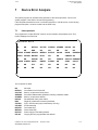
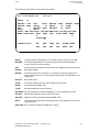
7
Device Error Analysis . . . . . . . . . . . . . . . . . . . . . . . . . . . . . . . . . . .
7–1
7.1
7.2
Interrupt stack . . . . . . . . . . . . . . . . . . . . . . . . . . . . . . . . . . . . . . . . .
Detailed error code . . . . . . . . . . . . . . . . . . . . . . . . . . . . . . . . . . . . . .
7–1
7–5
8
Memory Allocation and Organization
8–1
8.1
8.2
8.2.1
8.2.2
8.3
Segment allocation . . . . . . . . . . . . . . . . . . . . . . . . . . . . . . . . . . . . . .
Segment switch . . . . . . . . . . . . . . . . . . . . . . . . . . . . . . . . . . . . . . . .
Changing the segment switch . . . . . . . . . . . . . . . . . . . . . . . . . . . . . .
Processing data blocks with the segment switch . . . . . . . . . . . . . . . . .
Block lists . . . . . . . . . . . . . . . . . . . . . . . . . . . . . . . . . . . . . . . . . . . .
8–1
8–4
8–4
8–4
8–4
9
STEP 5 Operation Set with Programming Examples
9–1
9.1
9.1.1
9.1.2
9.2
9.2.1
9.2.2
9.2.3
9.2.4
9.2.5
9.2.6
9.2.7
9.2.8
9.2.9
9.3
9.3.1
General notes . . . . . . . . . . . . . . . . . . . . . . . . . . . . . . . . . . . . . . . . .
Numeric representation . . . . . . . . . . . . . . . . . . . . . . . . . . . . . . . . . . .
Condition codes of the PLC 135 WB/WB2/WD
..................
Basic operations . . . . . . . . . . . . . . . . . . . . . . . . . . . . . . . . . . . . . . . .
Logic operations, binary . . . . . . . . . . . . . . . . . . . . . . . . . . . . . . . . . .
Storage operations . . . . . . . . . . . . . . . . . . . . . . . . . . . . . . . . . . . . . .
Load and transfer operations . . . . . . . . . . . . . . . . . . . . . . . . . . . . . . .
Timing and counting operations . . . . . . . . . . . . . . . . . . . . . . . . . . . . .
Comparison operations . . . . . . . . . . . . . . . . . . . . . . . . . . . . . . . . . . .
Block calls . . . . . . . . . . . . . . . . . . . . . . . . . . . . . . . . . . . . . . . . . . . .
Code operations . . . . . . . . . . . . . . . . . . . . . . . . . . . . . . . . . . . . . . . .
Arithmetic operations . . . . . . . . . . . . . . . . . . . . . . . . . . . . . . . . . . . .
Other operations . . . . . . . . . . . . . . . . . . . . . . . . . . . . . . . . . . . . . . . .
Supplementary operations (FBs, FXs only) . . . . . . . . . . . . . . . . . . . . .
Logic operations, binary . . . . . . . . . . . . . . . . . . . . . . . . . . . . . . . . . .
.............................................
.......................
............
5–5
5–5
5–7
5–9
5–9
5–9
5–11
5–13
5–13
5–14
5–15
5–15
5–15
5–18
6–1
9–1
9–1
9–3
9–4
9–4
9–7
9–10
9–12
9–20
9–24
9–26
9–27
9–28
9–28
9–29
9.3.2
9.3.3
9.3.4
9.3.5
9.3.6
9.3.7
9.3.8
9.3.9
9.3.10
9.3.11
9.3.12
9.3.13
9.3.14
Setting operations . . . . . . . . . . . . . . . . . . . . . . . . . . . . . . . . . . . . . .
Timing and counting operations . . . . . . . . . . . . . . . . . . . . . . . . . . . . .
Enabling operations for timing and counting operations . . . . . . . . . . . .
Bit test operations (FB, FX only) . . . . . . . . . . . . . . . . . . . . . . . . . . . .
Load and transfer operations . . . . . . . . . . . . . . . . . . . . . . . . . . . . . . .
Logic operations, digital . . . . . . . . . . . . . . . . . . . . . . . . . . . . . . . . . .
Shift operations . . . . . . . . . . . . . . . . . . . . . . . . . . . . . . . . . . . . . . . .
Conversion operations . . . . . . . . . . . . . . . . . . . . . . . . . . . . . . . . . . .
Decrementing and incrementing . . . . . . . . . . . . . . . . . . . . . . . . . . . . .
Jump operations . . . . . . . . . . . . . . . . . . . . . . . . . . . . . . . . . . . . . . .
Processing operations . . . . . . . . . . . . . . . . . . . . . . . . . . . . . . . . . . . .
Operations for page memory processing . . . . . . . . . . . . . . . . . . . . . . .
Other operations . . . . . . . . . . . . . . . . . . . . . . . . . . . . . . . . . . . . . . .
9–29
9–30
9–32
9–33
9–34
9–35
9–35
9–36
9–36
9–37
9–40
9–42
9–43
10
Rules of Compatibility between the LAD, CSF
and STL Methods of Representation
.......................
10–1
10.1
10.2
10.3
General . . . . . . . . . . . . . . . . . . . . . . . . . . . . . . . . . . . . . . . . . . . . . .
Rules of compatibility for graphic program input (LAD, CSF) . . . . . . . . .
Rules of compatibility for program input in a statement list . . . . . . . . . .
10–1
10–2
10–5
11
Hardware . . . . . . . . . . . . . . . . . . . . . . . . . . . . . . . . . . . . . . . . . . . .
11–1
11.1
11.1.1
11.1.2
11.2
11.2.1
General notes on the PLC 135 WB/WB2 . . . . . . . . . . . . . . . . . . . . . .
Operating the PLC 135 WB/WB2 using the mode switch . . . . . . . . . . .
Eprom submodule for user program . . . . . . . . . . . . . . . . . . . . . . . . . .
General notes on the PLC 135 WD . . . . . . . . . . . . . . . . . . . . . . . . . .
Operating the PLC 135 WD . . . . . . . . . . . . . . . . . . . . . . . . . . . . . . . .
11–1
11–2
11–3
11–4
11–5
12
Programming and Test Functions with the Programmer
12–1
12.1
12.2
12.3
12.4
Requirement . . . . . . . . . . . . . . . . . . . . . . . . . . . . . . . . . . . . . . . . . .
Output of information . . . . . . . . . . . . . . . . . . . . . . . . . . . . . . . . . . . .
START PLC . . . . . . . . . . . . . . . . . . . . . . . . . . . . . . . . . . . . . . . . . . .
Block handling using the programmer . . . . . . . . . . . . . . . . . . . . . . . . .
.........
12–1
12–1
12–2
12–3
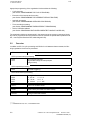
12.93
1 Introductory Remarks
1.1 Application
1
Introductory Remarks
1.1
Application
The PLC 135 WB/WB2/WD is a powerful interface controller for process automation
(controlling, reporting, monitoring). It is integrated in the SINUMERIK 880 / 880 GA2 and
SINUMERIK 840C numerical control and controls machine-related functional sequences
(auxiliary axes, tool magazines, monitors).
With the SINUMERIK 880 / 880 GA2 up to two PLCs and with the SINUMERIK 840C one PLC
(programmable logic controller) can be used per control. The user programs are developed in
the STEP 5 programming language or in high-level programming languages.
1.2
Programming languages
1.2.1
STEP 5 programming language
The operations available in STEP 5 enable the user to program functions ranging from simple
binary logic to complex digital functions and basic arithmetic operations.
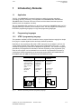
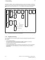
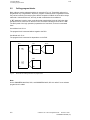
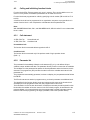
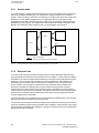
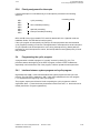
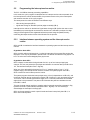
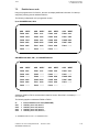
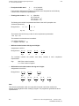
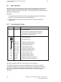
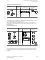
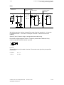
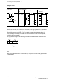
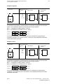
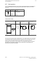
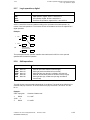
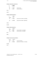
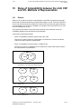
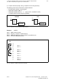
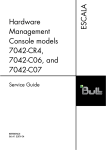
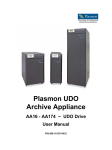
Depending on the programmer (PG) used a STEP 5 program may be written in the form of a
control system flowchart (CSF), ladder diagram (LAD) or statement list (STL) (Fig. 1.1), thus
enabling the programming method to be adapted to the application. The machine code (MC5)
generated by the programmers is identical for all three. Depending on the programmer (PG)
used, the user program can be translated from one method of representation to another by
conforming to certain programming conventions (see Section RULES OF COMPATIBILITY
BETWEEN LAD, CSF AND STL METHODS OF REPRESENTATION).
Ladder diagram
Statement list
Control system
flowchart
Programming with
symbols similar to
those used in schematic circuit diagrams
Complies with
DIN 19239
(draft)
Programming with
mnemonics
designating
functions
Programming
with graphic
symbols
Complies with
DIN 19239
(draft)
Complies with
IEC 117-15
DIN 40700
DIN 40719
DIN 19239
(draft)
LAD
STL
()
Fig. 1.1
CSF
A
AN
A
ON
O
=
I
I
I
I
I
Q
&
>=1
Methods of representing the STEP 5 programming language
© Siemens AG 1992 All Rights Reserved
SINUMERIK 840C/880 (PJ)
6FC5197- AA80
1–1
1 Introductory Remarks
1.2.2 High-level language programming
1.2.2
12.93
High-level language programming
The tasks of the PLC in a complex machine tool have grown enormously in the past. A highlevel language would be the optimum solution especially when parts of programs contain many
branches, jumps and comparisons. It is a quick way of formulating logical expressions which
must also be structured so that modules are comprehensible.
Structogram generators, which support structured programming with graphics, are also
available for program development using high-level languages. A structogram generator shows
the logical program structure in diagrammatical form and generates the source code
automatically.
For further information on high-level language programming see the Planning Guide ”PLC 135
WB S5-HLL”!
1.3
Programming
1.3.1
Program structure
The PLC software comprises the system program, the basic program and the user program.
The system program contains all statements and declarations for internal system functions.
The basic program has a flexible interface to the system program, it consists of technologyspecific functions and basic functions (e. g. generation of data blocks, NC-PLC interface
initialization, signal interchange with I/O modules). The basic program also contains pretested
function blocks written in STEP 5 and assembled to form function macros.
The system program and the basic program are supplied on EPROM submodules (in the case
of SINUMERIK 840C SW 3 and higher on hard disk or tape) and must not be modified in any
way. The user program is the total of all statements and declarations/data programmed by the
user.
The structure of the PLC 135 WB / WB2 / WD makes structured programming essential, i. e.
the program must be divided into individual, self-contained sections called blocks. This method
offers the following advantages:
•
•
•
•
•
•
Easy, lucid programming, even of large programs
Easy standardization of program sections
Simple program organization
Fast, easy modification
Simple program testing
Easy start-up
A number of block types, each of which is used for different tasks, is available for structuring
the user program:
•
Organization blocks (OBs)
The OBs serve as interface between operating system and user program.
•
Program blocks (PBs)
The PBs are used to break the user program down into technologically oriented sections.
1–2
© Siemens AG 1992 All Rights Reserved
6FC5197- AA80
SINUMERIK 840C/880 (PJ)
11.92
1 Introductory Remarks
1.3.1 Program structure
•
Function blocks (FBs and FXs)
The FBs are used to program frequently recurring complex functions (such as individual
controls, reporting, arithmetic and PID control functions).
•
Sequence blocks (SBs)
SBs are special forms of program blocks used primarily for processing sequencers.
•
Data blocks (DBs and DXs)
DBs are used for storing data or texts, and differ in both function and structure from all
other block types.
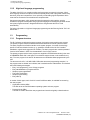
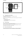
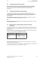
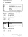
With the exception of the organization blocks, the maximum number of programmable blocks
of each type is 255. The number of organization blocks may not exceed 64; of these, only
OB 1-OB 7 are serviced by the operating system (see Section ”Organization blocks”).
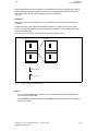
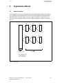
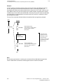
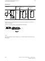
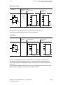
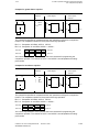
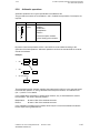
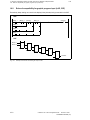
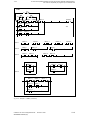
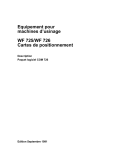
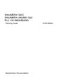
The programmer stores all programmed blocks in arbitrary order in program memory (Fig. 1.2).
1.3.2
Program organization
The manner in which the program is organized determines whether and in what order the
program, function and sequence blocks are executed. The order in which these blocks are
invoked is stipulated by programming the relevant calls (conditional or unconditional) in
organization blocks (see Section ”Programming the cyclic program”).
Like the other blocks, the organization blocks are stored in user memory.
a
a
a
a
a
a
a
a
a
a
a
a
a
a
a
a
a
a
a
a
a
a
a
a
a
a
a
aa
aa
aa
a
a
a
a
a
a
a
a
a
a
a
a
a
a
a
a
a
a
a
a
a
a
a
a
a
a
aa
aa
aa
a
a
a
PB1
PB2
•
•
FB1
•
•
DB1
•
SB10
•
FX1
•
•
OB1
Fig. 1.2
Storing the blocks in arbitrary order in program memory
Different organization blocks are provided for various methods of program execution (see
Section ”Organization blocks”).
© Siemens AG 1992 All Rights Reserved
SINUMERIK 840C/880 (PJ)
6FC5197- AA80
1–3
1 Introductory Remarks
1.3.2 Program organization
11.92
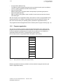
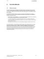
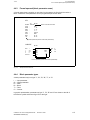
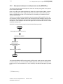
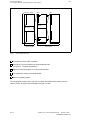
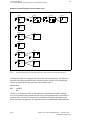
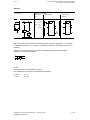
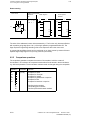
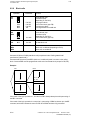
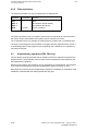
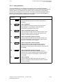
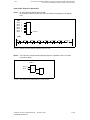
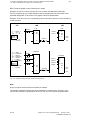
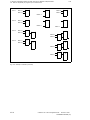
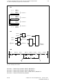
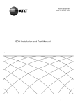
Organization, program, function and sequence blocks can invoke other program, function and
sequence blocks. The user program cannot call organization blocks. The maximum permissible
nesting depth is 62 blocks (all levels, Fig. 1.3), not including an accompanying data block, if
any.
OB 0 or
OB 1
FB
PB
FB
OB 1)
PB
PB
FB
FB
DB
FX
PB
DX
1)
OB 2 ... 7
OB
Organization block
PB
Program block
FB, FX Function block
DB, DX Data block
1
2
3
4
Fig. 1.3
Typical program organization in STEP 5; nesting depth 62
1.3.3
Program processing
5
6
7
The user program can be processed cyclically. Interrupt processing with organization blocks is
also possible.
•
Cyclic program processing
For cyclic program processing organization block OB 1 is available. This block is
processed cyclically and calls up the blocks programmed in it.
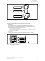
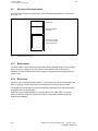
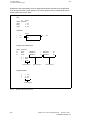
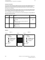
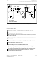
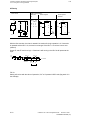
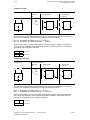
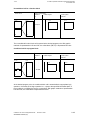
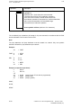
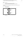
•
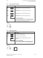
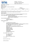
Interrupt-controlled processing
Cyclic program processing can be interrupted for interrupt servicing. For this, organization
blocks OB 2 to OB 7 are available (Fig. 1.4). OB 2 and OB 5 can only be executed in
special mode.
1–4
© Siemens AG 1992 All Rights Reserved
6FC5197- AA80
SINUMERIK 840C/880 (PJ)
11.92
1 Introductory Remarks
1.3.3 Program processing
OB 2
OB 3
Process interrupt processing
OB 4
Aperiodic triggering
OB 5
Timed interrupt processing
Fig. 1.4
OB 6
OB 7
Types of interrupt processing
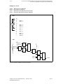
There are 2 modes available to the user for interrupting cyclic processing:
•
Normal mode
Here interruption of cyclic processing is only possible at the block limits (Fig. 1.5).
If you are working in normal mode, make sure that non-interruptible programs do not
require longer than 10 ms. Otherwise errors can occur:
– The MC5 times become imprecise.
– If the 10 ms limit is exceeded by a lot, the mutual NC-PLC monitoring can respond
(message "PLC CPU failed").
•
Special mode
In special mode the user program can be interrupted after every MC 5 command.
OB 1
PB
Interruption points
Fig. 1.5
Program processing in normal mode
© Siemens AG 1992 All Rights Reserved
SINUMERIK 840C/880 (PJ)
6FC5197- AA80
1–5
1 Introductory Remarks
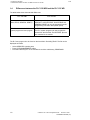
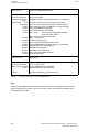
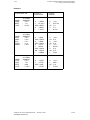
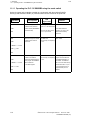
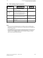
1.4 Differences between the PLC 135 WB2 and the PLC 135 WD
1.4
12.93
Differences between the PLC 135 WB2 and the PLC 135 WD
The table below shows the essential differences:
PLC 135 WB2
PLC 135 WD
Start-up switch
(RUN, STOP, GENERAL RESET)
No start-up switch (the functions WARM
RESTART, COLD RESTART, BOOTSTRAP and
GENERAL RESET can only be executed from the
programming unit and/or the operator panel).
EPROM submodules for PLC
system program and user program
No EPROM submodules.
The PLC system program and user program are
booted from the hard disk. The RESTART Eproms
are contained in the module.
The PLC user program is to be found on the hard disk in file ANW_PROG. The file can be
displayed as follows:
•
•
•
1–6
Select SERVICES operating area
Press DATA MANAGEMENT softkey
First select directory PLC in the user branch and then subdirectory PROGRAMS.
© Siemens AG 1992 All Rights Reserved
6FC5197- AA80
SINUMERIK 840C/880 (PJ)
11.92
2 Program Blocks
2.1 Programming program blocks
2
Program Blocks
2.1
Programming program blocks
The information presented in this Section applies to the programming of organization, program
and sequence blocks. These three block types are all programmed in the same way (see Section ”Data blocks” and Section ”Function blocks”). Program, organization and sequence
blocks can be programmed in all three STEP 5 modes of representation (STL, LAD, CSF)
using the basic operations.
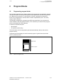
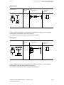
The first step in programming a program block (PB) is the specification of a program block
number between 0 and 255 (example: PB 25). This is followed by the actual control program,
which is terminated with a "BE" statement.
An S5 block comprises two parts:
•
•
Block header
S5 operations (block body)
The block header, which the programmer generates automatically, takes up five words in
program memory.
A program block should always be a self-contained program. Logical links to other blocks
serve no practical purpose.
PB25
Block header
A
I 5.7
STEP 5 program
BE
Fig. 2.1
Structure of a program block
© Siemens AG 1992 All Rights Reserved
SINUMERIK 840C/880 (PJ)
6FC5197- AA80
2–1
2 Program Blocks
2.2 Calling program blocks
2.2
12.93
Calling program blocks
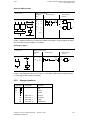
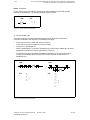
Block calls are used to release the blocks for execution (Fig. 2.2). These block calls can be
programmed only in organization, sequence, program or function blocks. Organization blocks
may not be invoked by the user program, with the exception of OB180. A block call is comparable with a "subroutine branch", and may be both conditional and unconditional.
A "BE" statement is used to return to the block that contained the block call. No further logic
operations can be carried out on the RLO in the "new block" following a block call or a "BE".
The RLO (result of the logic operation) is passed to the "new block", and can be evaluated
there.
Unconditional call: JU xx
The program block is executed without regard to the RLO.
Conditional call: JC xx
The program block is executed in dependence on the RLO.
PB 1
JU
O
PB 5
A
I 1.0
PB5
I 5.3
JC
PB 10
A
I 2.0
PB10
BE
BE
PB 6
O I 3.0
A
JC
A
BE
Fig. 2.2
I 1.5
PB 6
I 3.2
BE
Block calls for enabling execution of a program block
Note:
On the SINUMERIK 880 GA2, SW1, and SINUMERIK 840C, OB 19 is called if a non-existent
program block is called.
2–2
© Siemens AG 1992 All Rights Reserved
6FC5197- AA80
SINUMERIK 840C/880 (PJ)
11.92
3 Data Blocks
3.1 Programming data blocks
3
Data Blocks
3.1
Programming data blocks
The data required by the user program is stored in data blocks (DBs and DXs). No STEP 5
operations are programmed in these blocks.
Data can be of the following types:
•
•
•
Arbitrary bit patterns, e. g. for plant status indications
Numbers (hexadecimal, binary, decimal), e. g. for times and results of arithmetic
operations
Alphanumeric characters, e. g. for message texts
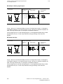
Generation of a data block on the programmer begins by specifying a data block number
between 1 and 255. Each data block (see example: DX 99 in fig. 3.1) may comprise as many
as 2043 data words (of 16 bits each). DW 0 to DW 255 can be addressed via load and transfer
operations. Data words > 255 can be addressed using O B180. The data must be entered by
word, beginning with data word 0; data word 0 (DW 0) should not be used, however, as certain
function blocks employ it as a buffer.
One word is reserved in program memory for each data word. The programmer also generates
a block header for each data block; the header takes up five words in program memory.
Data blocks DB 2, 3 and 4 are interface blocks between the NC and the PLC 135 WB.The
programmer (PG) prevents deletion and modification of these blocks.
DX99
DW0
DW1
DW2
DW3
DW4
DW5
Block header
NOP
3 F
4 A
0110 0100 0000 1111
2
U
NOP
NOP
Data words
0 to 2042
DW2042
Fig. 3.1
Structure of a data block
© Siemens AG 1992 All Rights Reserved
SINUMERIK 840C/880 (PJ)
6FC5197- AA80
3–1
3 Data Blocks
3.2 Calling data blocks
3.2
11.92
Calling data blocks
Data blocks can be called unconditionally only. Once called, a data block remains in force until
the next is invoked.
User data blocks must not conflict with those required by the system.
A data block call can be programmed in an organization, program, function or sequence block.
The "C DB xxx" or "CX DX 200" command calls a data block.
Example 1:
Transferring the contents of data word 1 of data block 10 to data word 1 of data block 20
(Fig. 3.2).
:C
:L
:C
:T
DB10
DW1
DB20
DW1
DB 10
DW0
DW1
DW255
DB 20
DW0
DW1
Fig. 3.2
3–2
Calling a data block
© Siemens AG 1992 All Rights Reserved
6FC5197- AA80
SINUMERIK 840C/880 (PJ)
12.93
3 Data Blocks
3.2 Calling data blocks
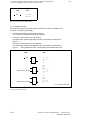
When a program block in which a data block is addressed calls another program block that addresses another data block, the latter is valid only in the program block that was called. The
original data block is again valid following return to the calling block
(Fig. 3.3).
Example 2:
Data block 10 is called in program block 7, and the data in this data block are subsequently
processed.
Program block 20 is then called and executed. Data block 10 is still valid. Only when data
block 11 has been opened is the data area changed. Data block 11 is now valid until program
block 20 has terminated.
Data block 10 is once again valid following the return to program block 7.
PB 7
C
DB10
JU
PB 20
PB20
C
BE
DB11
BE
DB 10 is open
DB 11 is open
Fig. 3.3
Validity range of a selected data block
Notes:
•
If a non-existent data word or a data word of an unopened data block is addressed, the
PLC goes into the stop state.
•
With SINUMERIK 880 GA2, SW1, and SINUMERIK 840C, OB19 is called if a non-existent
data block is called.
© Siemens AG 1992 All Rights Reserved
SINUMERIK 840C/880 (PJ)
6FC5197- AA80
3–3
3 Data Blocks
3.3 Processing data words greater than data word 255
3.3
11.92
Processing data words greater than data word 255
The size of data blocks was increased from 256 words to 2K words. This gives the user 2043
words as a data field per data block.
The corresponding DBs can be generated using the function macro FB 11 (EINR_DB). The
system block OB 180 is provided for addressing the additional data words with STEP 5
statements.
Function description of the OB 180:
OB 180 is used to address data words and data bytes in data blocks over 256 long (up to
2043 words). Only 256 data words (data words 0 to 255) can be addressed using STEP5
statements. In order to address the remaining data words of a longer data block, the initial
address of the open data block is shifted in OB 180. The number of data words by which the
initial address is shifted must be transferred to ACCU 1 (e.g. with L KF + 12).
The OB 180 can be invoked with the commands JU OB or JC. The data block length is
reduced by the corresponding number of words so that a validity check can still be carried out
when the data block is written to. If the shift specified is bigger than the data block length or if
no data block is open, no shift is performed and the RLO is set to 1. RLO is reset to 0 on a
legal shift.
It is possible to switch back to the original initial address by opening the data block again.
If OB 180 is called several times in a row, the shifts are added up until the data block is
reopened. It is not possible to shift in the negative direction.
Example:
DB222
DW0
DW1
DW2
DW3
DW4
DW5
DW6
DW7
DW8
DW9
:
:
:
:
:
:
:
:
:
:
KH=0000
KH=1111
KH=2222
KH=3333
KH=4444
KH=5555
KH=6666
KH=7777
KH=8888
KH=9999
Shift by 5 words:
L
JU
KF +05
OB180
After shifting:
DB222
3–4
DW0
DW1
DW2
DW3
DW4
:
:
:
:
KH=5555
KH=6666
KH=7777
KH=8888
: KH=9999
© Siemens AG 1992 All Rights Reserved
6FC5197- AA80
SINUMERIK 840C/880 (PJ)
12.93
4 Function Blocks
4.1 General remarks
4
Function Blocks
4.1
General remarks
Function blocks are used to implement frequently recurring or extremely complex functions.
The PLC 135 WB / WB2 / WD interface control also permits function blocks of type FX to be
programmed in addition to the previously used function block type FB. The handling of both types is identical.
Functions blocks (FBs and FXs) are as much a part of the user program as, for example,
program blocks. There are three basic differences between function blocks and organization,
program or sequence blocks:
•
Function block can be initialized, i. e. a function block's formal parameters can be replaced
by the actual operands with which the function block is called.
•
In contrast to organization, program and sequence blocks, an extended operation set
comprising the STEP 5 supplementary operations can be used to program function blocks,
and only function blocks.
•
The program in a function block can be generated and logged in statement list form only.
The function blocks in a user program represent complex, self-contained functions. The user
can program function blocks in the STEP 5 programming language or purchase them from
Siemens as a software product. In addition, a number of pretested, technology-specific
function blocks can be assembled to form function macros and linked into the basic program.
The user can call these macros as he would a function block, but he cannot modify them.
These blocks are written in assembly language and are also referred to as "resident" or
"integral function blocks".
© Siemens AG 1992 All Rights Reserved
SINUMERIK 840C/880 (PJ)
6FC5197- AA80
4–1
4 Function Blocks
4.2 Structure of function blocks
4.2
11.92
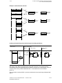
Structure of function blocks
A function block comprises a block header, name and parameter declaration, and the block
body (Fig. 4.1).
Block header
Name and parameter
declarations
Block body with STEP
5 program or assembly
language statements
Fig. 4.1
Structure of a function block
4.2.1
Block header
The block header contains all the information which the programmer needs in order to display
the function block in graphic form and check the operands when the function block is
initialized. The user must enter the header (using the programmer) before programming the
function block.
4.2.2
Block body
The block body contains the actual program, i. e. describes the function to be executed in the
STEP 5 language. Only the block body is processed when the function block is called.
The programmer echoes the block name and parameter declaration when integral assemblylanguage function blocks are called.
When the "first executable statement" in the block body is the "ASM" STEP 5 command
(switch to assembly code), the processor executes the subsequent assembly language
statements immediately.
4–2
© Siemens AG 1992 All Rights Reserved
6FC5197- AA80
SINUMERIK 840C/880 (PJ)
12.93
4.3
4 Function Blocks
4.3 Calling and initializing function blocks
Calling and initializing function blocks
Function blocks (FBs, FXs) are present only once in memory. They can be called once or more than once by a block, and different parameters can be used for each call.
Function blocks are programmed or called by specifying a block number (FB 0 to 255 or FX 0
to 255).
A function block call can be programmed in an organization, sequence or program block or in
another function block. A call comprises the call statement and the parameter list.
Note:
With SINUMERIK 880 GA2, SW1, and SINUMERIK 840C, OB19 is called if a non-existent data
block is called.
4.3.1
Call statement
JU FBn, DO FXn
JC FBn, DOC FXn
Unconditional call
Conditional call
Unconditional call:
The function block is executed without regard to the RLO.
Conditional call:
The function block is executed only if the previous result of logic operation is zero
(RLO = 1).
4.3.2
Parameter list
The parameter list immediately follows the call statement (Fig. 4.2), and defines all input
variables, output variables and data. The parameter list may contain no more than 40 variables.
The variables from the parameter list replace the formal parameters when the function block is
executed. The programmer (PG) monitors the order in which the variables are entered in the
parameter list.
The programmer automatically generates, but does not display, the jump statement that follows
the FB call.
The FB call reserves two words in program memory, and each parameter one additional word.
The identifiers for the function block's inputs and outputs and the name of the function block
are displayed on the programmer when the user programs the function block.
This information is in the function block itself. It is therefore necessary that all required function
blocks either be resident as function macros in the PLC's basic program, be transferred to the
program diskette, or be entered directly into the programmable controller's program memory
before function block programming can begin (for details, refer to the Operator' Guide).
© Siemens AG 1992 All Rights Reserved
SINUMERIK 840C/880 (PJ)
6FC5197- AA80
4–3
4 Function Blocks
4.3.2 Parameter list
11.92
PB 3
Call
is generated by the
programmer
Parameter list
Call
is generated by the
programmer
Parameter list
JU
JU
I
T
F
Q
AI
AI
JU
JU
I
T
F
F
FB 5
+
5
2.4
5
3.1
6.0
3.2
5.1
FB 5
+
5
5.2
7
3.6
5.0
FB 5
Block header
A =PAR 1
O =PAR 2
O =PAR 3
Formal
parameters
= =PAR 4
BE
BE
Fig. 4.2
Calling a function block
4.4
Programming function blocks
In keeping with its structure, a function block is generated in two parts:
the block header and the block body.
The block header must be entered before the block body (STEP 5 program). The block header
contains
•
•
•
•
The library number
The name of the function block
The formal operands (the names of the block parameters)
The block parameters
4.4.1
Library number
The library number can be a number between 0 and 65535. The library number of a function
block is unconnected with its symbolic or absolute parameters.
A library number should be assigned only once to permit unique identification of a function
block. Standard function blocks have a product number.
4.4.2
Name of the function block
The name that identifies the function block may comprise no more than eight characters, the
first of which must be a letter. The name is not identical with the symbolic plant identifier.
4–4
© Siemens AG 1992 All Rights Reserved
6FC5197- AA80
SINUMERIK 840C/880 (PJ)
11.92
4 Function Blocks
4.4.3 Formal operand (block parameter name)
4.4.3
Formal operand (block parameter name)
A formal operand may comprise no more than four characters, the first of which must be a
letter. A maximum of 40 parameters can be programmed per function block.
STL
NAME
ZU-E
RME
ESB
UEZ
ZEIT
ZU-A
BEA
LSL
:JU
FB 201
:E-ANTR
:
DW1
:
I 3.5
:
F 2.5
:
T 2
:
KT010.1
:
DW2
:
Q 2.3
:
Q 6.0
Name of the function block
Formal operands (names of the block parameters)
LAD/CSF
FB 201
DW 1
I
3.5
F
2.5
T
2
KT010.1
ZU-E
RME
ESB
UEZ
ZEIT
ZU-A
BEA
LSL
DW
Q
Q
2
2.3
6.0
Formal operands (names of the block parameters)
Fig. 4.3
Sample function block call
4.4.4
Block parameter types
A block parameter may be of type "I", "Q", "D", "B", "T", or "C".
I
Q
D
B
T
C
=
=
=
=
=
=
Input parameter
Output parameter
Data
Block
Timer
Counter
In graphic representation, parameters of type "I", "D", "B" and "C" are shown to the left of
the function symbol and those of type "Q" to the right.
© Siemens AG 1992 All Rights Reserved
SINUMERIK 840C/880 (PJ)
6FC5197- AA80
4–5
4 Function Blocks
4.4.4 Block parameter types
11.92
Operations to which parameters are to be assigned (substitution operations) are programmed
in the function block with formal operands. The formal operands may be addressed at various
locations within the function block.
STL
NAME
ANNA
BERT
HANS
:JU
FB 202
:EXAMPLE
:
I 13.5
:
F 17.7
:
Q 23.0
LAD/CSF
FB 202
I
F
13.5
17.7
ANNA
BERT
HANS
Q
23.0
Program in the function block
NAME
ID
ID
ID
:EXAMPLE
:ANNA
:BERT
:HANS
:A
:A
:=
I/Q/D/B/T/C:
I/Q/D/B/T/C:
I/Q/D/B/T/C:
I
I
Q
BI/BY/W/D:
BI/BY/W/D:
BI/BY/W/D:
BI
BI
BI
= ANNA
= BERT
= HANS
Formal operand
Parameter type
Parameter type
Program executed
:A
:A
:=
I 13.5
F 17.7
Q 23.0
Actual operand
Fig. 4.4
4–6
Example: Calling a function block
© Siemens AG 1992 All Rights Reserved
6FC5197- AA80
SINUMERIK 840C/880 (PJ)
11.92
4.4.5
4 Function Blocks
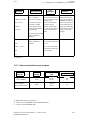
4.4.5 Block data type and permissible actual operand
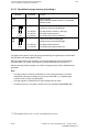
Block data type and permissible actual operand
Parameter
type
Data type
Permitted actual operands
I, Q
BI
for an operand with bit address
I
Q
F
n.m inputs
n.m output
n.m flags
BY
for an operand with byte address
IB
QB
FB
DL
DR
PB
n
n
n
n
n
n
input bytes
output bytes
flag bytes
data byte left
data byte right
peripheral bytes
W
for an operand with word address
IW
QW
FW
DW
PW
n
n
n
n
n
input words
output words
flag words
data words
peripheral words
D
for an operand with double word address
ID
QD
FD
DD
n
n
n
n
input double words
output double words
flag double words
data double words
KM
KY
for a binary pattern (16-digit)
for two absolute numbers bytewise in the
range of 0 to 255
for a hexadecimal pattern up to four digits
for a symbol (max. 2 alphanumeric
characters)
for a time value (BCD coded) with time
grid 1.0 to 999.3
for a count value (BCD coded) 0 to 999
for a fixed-point number -32768 to
+32767
for a floating-point number
Constants
D
KH
KS
KT
KC
KF
KG
B
data type definitions are not permitted
DB
FB
FX
PB
SB
n data blocks, the command B =
"Parameter" n is executed
n function blocks (only permissible
without parameters)
n are called unconditionally with the
command JU FB n or BA FX n
n program blocks are called
unconditionally (JU..n)
n Sequence blocks are called
unconditionally (JU..n)
T
data type definitions are not permitted
T
timer; the time must be programmed as
a data or programmed as a constant in
the function block
C
data type definitions are not permitted
C
counter; the count value must be
programmed as a data or programmed
as a constant in the function block
© Siemens AG 1992 All Rights Reserved
SINUMERIK 840C/880 (PJ)
6FC5197- AA80
4–7
11.92
5 Organization Blocks
5.1 General remarks
5
Organization Blocks
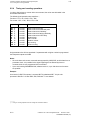
5.1
General remarks
The organization blocks form the interface between the system program and the user program.
The organization blocks (OBs) are as much a part of the user program as are program blocks,
sequence blocks and function blocks, but only the system program can invoke them. A user
can only program organization blocks; he cannot invoke them (with the exception of OB 180)
(Fig. 5.1).
OB
PB
BE
BE
OB
PB
BE
System program
BE
FB
BE
FB
BE
User program
OB Organization block
PB Program block
FB Function block
Fig. 5.1
PLC program
© Siemens AG 1992 All Rights Reserved
SINUMERIK 840C/880 (PJ)
6FC5197- AA80
5–1
5 Organization Blocks
5.1 General remarks
12.93
Appropriate programming of the organization blocks enables the following:
•
Cyclic execution
(see Section PROGRAMMING THE CYCLIC PROGRAM)
•
Execution of the interrupt service routine
(see Section PROGRAMMING THE INTERRUPT SERVICE ROUTINE)
•
Aperiodic processing
(see Section PROGRAMMING APERIODIC PROCESSING)
•
Time-controlled processing
(see Section PROGRAMMING TIMED-INTERRUPT PROCESSING)
•
Shift of a DB initial address
(see Section PROCESSING DATA WORDS GREATER THAN DATA WORD 255)
The organization blocks are programmed in the same manner as program or sequence blocks,
and can be programmed and documented in all three methods of representation (statement list
STL, control system flowchart CSF, ladder diagram LAD).
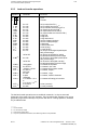
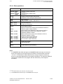
5.2
Overview
In addition to OB 1 for cyclic processing and OB 20 for cold restart and warm restart, the following organization blocks can be processed:
OB 1
cyclic processing
OB for process interrupt processing
OB 2
OB 3
I/Os causing interrupts
signal state change at interrupt inputs
(edge control)
OB for aperiodic processing
OB 4
aperiodic triggering
OB for timed interrupt processing
OB 5
OB 6
OB 7
time grid with
n . 2.5 ms
n = 1, 2, 3
m . 10 ms
m = 1...9
p . 100 ms
p = 1...255
OB 19 1)
call of non-existent blocks
OB 20
system start (cold restart and warm restart)
OB 180
change of DB-initial address
_______
1)
5–2
SINUMERIK 880 GA2, SW 1, and SINUMERIK 840C
© Siemens AG 1992 All Rights Reserved
6FC5197- AA80
SINUMERIK 840C/880 (PJ)
12.93
5 Organization Blocks
5.2 Overview
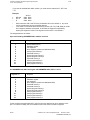
Organization block OB 1 must always be available. Organization blocks OB 2 to OB 7 are not
mandatory. If they are missing, the call must be disabled by entering the machine data (see
Interface Description Part 1: Signals, ”PLC MD bits for basic program”); otherwise the control
goes into the STOP state.
When changing the processing level (execution of an OB is interrupted by interrupt processing
or when another OB is called) all MC5 registers (ACCU 1, ACCU 2, RLO etc.) and flag bytes
224 to 255 or MB 200 to 255 1) (if MD bit 6026.3 is set) are saved or reconstituted. Branching
to the DB opened in the respective processing level is also saved (as are changes implemented by OB 180).
The "event counter processing timeout in OB 2 to OB 7" registers record how much requests
for interrupt processing were lost while an interrupt-controlled program was being executed
(see Section "Detailed error code" and Section "Delay during process interrupt processing").
In addition, a machine data bit can be set to cause the control to go into the STOP state when
a processing timeout occurs; otherwise a respective bit is set in flag byte 6 (see Interface
Description Part 1: Signals).
5.3
Points of interruption
The cyclically processed user program can be interrupted in two different ways for interrupt
servicing:
•
in normal mode
•
in special mode
Normal or special mode can be selected via a machine data bit (see Interface Description
Part 1: Signals, "PLC MD bits for basic program").
_______
1)
SINUMERIK 880 GA2, SW 1, and SINUMERIK 840C
© Siemens AG 1992 All Rights Reserved
SINUMERIK 840C/880 (PJ)
6FC5197- AA80
5–3
5 Organization Blocks
5.3.1 Normal mode
5.3.1
11.92
Normal mode
In normal mode the cyclically processed program can only be interrupted at the block limits by
interrupt-controlled processing (Fig. 5.2). Only when a change is made from one block to
another - either by calling a new block or by returning to a higher-order block after a block end
statement - can the system program call up an organization block for interrupt servicing.
Organization blocks OB 2 and OB 5 cannot be called up in normal mode. If these blocks are
available in the user program and enabled via machine data (see Interface Description Part 1:
Signals, "PLC MD bits for basic program"), they are nevertheless not processed.
OB 1
PB 3
JU
FB 5
FB 5
BE
JU
PB 3
PB 13
JU
BE
BE
PB 13
BE
Point of interruption
at which interrupt servicing can be erfolgen
Fig. 5.2
Point of interruption of the cyclically processed program in normal mode
5.3.2
Response time
In normal mode interrupt-controlled processing cannot normally take place while a block is
being processed. An interrupt is only serviced on a block change, i.e. when a block is called or
terminated. The maximum response time between an interrupt occuring and being serviced is
therefore, in the worst case, the processing time of the longest block. If two alarms occur
simultaneously, the response time for the interrupt increases for the interrupt with lower
priority. First the cyclic program is processed up to the next block change and then the
processor processes the "interrupt service routine" with the highest priority. Once the
"interrupt service routine" with the higher priority has been completed, the "interrupt service
routine" with lower priority is then processed. The response time of this lower-priority program
has thus been increased by the processing time of the higher-priority program (see Section
"Priority assignments for interrupts").
If several interrupts occur simultaneously, the interrupt with the lowest priority is only serviced
when all higher-priority interrupts have been serviced.
The priorities of an interrupt-controlled processing can be shifted if an interrupt occurs while an
interrupt-controlled program is being processed. After completion of the servicing of the higherpriority interrupt, the priorities are reassigned, causing the response time for the lowest-priority
interrupt to be further increased.
5–4
© Siemens AG 1992 All Rights Reserved
6FC5197- AA80
SINUMERIK 840C/880 (PJ)
11.92
5.3.3
5 Organization Blocks
5.3.3 Special mode
Special mode
In special mode the user program can be interrupted after each MC5 instruction (dependent on
PLC MD 6051.0, see Interface Description Part 1: Signals, "PLC MD bits for basic program").
The last command is completed; at the end of the command the timed and process interrupts
are enabled. The maximum response time in special mode is therefore reduced to the
processing time of a command, if interrupt processing has not yet been activated.
5.3.4
Semaphore technique within the processing levels of a PLC
(LIM/SIM)
The commands LIM and SIM give the user a way of protecting sections of programs from
interruptions by higher priority processing levels within a PLC. Lock bits, which each apply to
an OB, can be first set and then reset in a user program to enclose a section of the program.
This section cannot be interrupted by the OB to which a set lock bit applies even if this OB
has a higher priority.
Command sequence:
The command LIM loads the OB locks into the ACCU 1 (low byte), which can now be changed
by setting and resetting individual bits. Setting a bit disables the OB concerned and resetting
the bit enables it. Either all or any combination of OB lock bits can be set or reset. If, after an
OB has been disabled, the corresponding timed or process interrupt occurs, the higher priority
OB is not executed immediately by the system program but stored in a buffer.
The command SIM supplies the OB lock bits with the content of ACCU 1 (low byte). It also
checks whether lock bits were reset. If they were, it checks whether a request was put in the
buffer for the corresponding OB. If it was, this OB is invoked, as long as there is no request
for a higher-priority OB.
If a time or process interrupt occurs more than once while the lock bit for the corresponding
OB is set, requests are lost. In the diagnostics DB (DB 1) a counter for each OB keeps count
of how many requests are lost. Flag 6.1 is also set as a group identifier for OB 2 to OB 7.
Assignment of the lock bits (=ACCU 1 low byte):
Bit
7
6
5
4
3
2
OB 7 OB 6 OB 5 OB 4 OB 3 OB 2
1
0
not
not
assigned assigned
1 = OB x disabled
0 = OB x enabled
© Siemens AG 1992 All Rights Reserved
SINUMERIK 840C/880 (PJ)
6FC5197- AA80
5–5
5 Organization Blocks
5.3.4 Semaphore technique within the processing levels of a PLC (LIM/SIM)
11.92
Example:
A user program is processed cyclically, during which the lock bit for the OB5 (time interrupt
2.5 ms - time grid) is set. If a timed interrupt occurs in the 2.5 ms time grid, OB5 is not
immediately executed by the system program but the request is put in a buffer. When the lock
bit for OB5 is reset in the cyclic user program, the system program recognizes that a request
for OB5 was put in the buffer and executes OB5. In this way, the user can make sure that data
is not changed by an interrupt before it is stored in the form in which it is required for further
processing by the progam.
The use of the commands LIM and SIM can be explained with a programming example:
OB 1
JU FB 200
FB 200
LIM
L
KH 0020
OW
SIM
;Read the OB lock bits
;Load constant for disabling OB 5
;Set lock bit OB 5 in ACCU1
;Write lock bit
BE
This section of the
program cannot be
interrupted by OB 5.
Access to
protected data
A timed interrupt
occurring in the 2.5 time
grid would be serviced
after this section.
LIM
L
KH FFDF
UW
SIM
;Read the OB lock bits
;Load constant for disabling OB 5
;Read lock bit OB 5 in ACCU 1
;Write lock bit
BE
Note:
Do not test program sections containing the commands LIM and SIM with the programmer
function "status block" because the locked program sections could be interrupted.
5–6
© Siemens AG 1992 All Rights Reserved
6FC5197- AA80
SINUMERIK 840C/880 (PJ)
11.92
5 Organization Blocks
5.3.5 Semaphore technique in multiprocessor mode (SES/SEF)
Semaphore technique in multiprocessor mode (SES/SEF) 1)
5.3.5
The user has the use of 32 user semaphores; these are used to protect global memory areas
in the communication RAM.
If two or more PLCs use certain global memory areas in the communication RAM in common,
there is a danger that the PLCs might overwrite each other's data or that invalid temporary
states of the data may be read out. For this reason it is necessary to coordinate access to
common memory areas.
The PLCs are coordinated using semaphores and the commands SES and SEF: A PLC can
only access the common memory area if it has successfully set the semaphore (SES) for that
memory area. The semaphore can only be set by one PLC at a time. If a PLC cannot set the
semaphore or if the semaphore has been reset again with the command SEF, the PLC cannot
access the memory area.
All the PLCs concerned must contain a block with the following structure:
Begin
Set semaphore: SES n (n=0 to 31)
Operation successful?
yes
no
Access to the
global memory
areas protected by the
semaphore
Reset semaphore: SEF n
End
The commands SES and SEF must be used by all PLCs which need to access synchronisiert
a common memory area. The use of SES and SEF guarantees that a piece of information belonging to a PLC can be transferred in or out of a memory area without interruption by another
PLC.
_______
1)
SINUMERIK 880 only
© Siemens AG 1992 All Rights Reserved
SINUMERIK 840C/880 (PJ)
6FC5197- AA80
5–7
5 Organization Blocks
5.3.5 Semaphore technique in multiprocessor mode (SES/SEF)
11.92
Command description:
The command "Set semaphore" (SES) sets a byte in the communication RAM assigned to the
semaphore for the PLC executing the command (provided it has not already been set by
another PLC). As long as this PLC reserves this byte the other PLCs cannot access the area
protected by the semaphore.
The command "Reset semaphore" (SEF) resets the byte in the communication RAM assigned
to the semaphore. After this, the protected memory area can be read and written by the other
PLCs. A semaphore can only be reset by the PLC that set it.
The commands SES and SEF scan the state of the specified semaphore. The flags ANZ0 and
ANZ1 are influenced as follows:
ANZ1
ANZ0
0
0
1
0
Meaning
Evaluation
SES:
Semaphore is already set by another PLC and
cannot be set.
SEF:
Semaphore is not set or is set by another PLC
and cannot be reset
SPZ
SES:
Semaphore is set
SEF:
Semaphore is reset
SPN, SPP
Example:
PLC 1
FB 200
PLC 2
DB 59
Semaphore 20 set
program section
data processed
e.g. DB 59
: SEF20
ENDE : BE
5–8
: SES20
: JZ=ENDE
aaaaaaaaaaaaaaaaaaaaaaaaaaaaa
a
a
a
a
a
a
a
a
aaaaaaaaaaaaaaaaaaaaaaaaaaaaa
a
a
a
a
a
a
a
a
a
a
aaaaaaaaaaaaaaaaaaaaaaaaaaaaa
a
a
a
a
a
a
a
a
aaaaaaaaaaaaaaaaaaaaaaaaaaaaa
a
a
a
a
a
a
a
a
a
a
aaaaaaaaaaaaaaaaaaaaaaaaaaaaa
a
a
a
a
a
a
a
a
a
aaaaaaaaaaaaaaaaaaaaaaaaaaaaa
a
a
a
a
a
a
a
a
a
aaaaaaaaaaaaaaaaaaaaaaaaaaaaa
a
a
a
aa
aa
aa
aa
a
aaaaaaaaaaaaaaaaaaaaaaaaaaaaa
a
a
a
a
a
a
aaaaaaaaaaaaaaaaaaaaaaaaaaaaa
a
a
a
a
a
a
a
a
a
aaaaaaaaaaaaaaaaaaaaaaaaaaaaa
a
a
a
a
a
a
a
a
a
aaaaaaaaaaaaaaaaaaaaaaaaaaaaa
a
a
a
aa
aa
aa
aa
a
aaaaaaaaaaaaaaa
a
: SES20
: JZ=ENDE
FB 201
Semaphore 20 set
program section
data processed
e.g. DB 59
: SEF20
ENDE : BE
© Siemens AG 1992 All Rights Reserved
6FC5197- AA80
SINUMERIK 840C/880 (PJ)
11.92
5.3.6
5 Organization Blocks
5.3.6 Priority assignment for interrupts
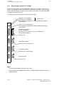
Priority assignment for interrupts
If several interrupts occur simultaneously, the interrupts are processed in the following
sequence:
OB 1
OB 7
OB 6
OB 5
OB 4
OB 3
OB 2
cyclic processing
Increasing priority
time-controlled processing
aperiodic processing
interrupt-controlled processing
OB 2 and OB 5 are only processed if PLC machine data bit 6051.0 is 0 (Special mode see
Installation Guide, "PLC MD bits for basic program").
If the cyclic program is interrupted by an interrupt, all interrupts present are serviced before
cyclic program processing is continued. This applies both to interrupts which cause interruption
of cyclic operation and all interrupts which occur during interrupt servicing. Hereby after the
processing of each interrupt service routine, the interrupt with the next highest priority is found
and processed.
5.4
Programming the cyclic program
A programmable controller's program is "normally" scanned cyclically (Fig. 5.4). The
processor starts at the beginning of the STEP 5 program, scans the STEP 5 statements
sequentially until it reaches the end of the program, and then repeats the entire procedure.
5.4.1
Interface between system program and cyclic program
Organization block OB 1 is the interface between the system program and the cyclic user
program. The first STEP 5 statement in OB 1 is also the first statement in the user program,
i. e. is equivalent to the beginning of the cyclic program.
The program, sequence and function blocks comprising the cyclic program are called in
organization block 1. These blocks may themselves contain block calls, i. e. the blocks can be
nested (see Section "Program organization").
© Siemens AG 1992 All Rights Reserved
SINUMERIK 840C/880 (PJ)
6FC5197- AA80
5–9
5 Organization Blocks
5.4.1 Interface between system program and cyclic program
Operating system
11.92
OB 1
1
PB n
2
PB call
OB 1 call
etc.
5
4
3
BE
Operating system
Fig. 5.4
BE
User program
Cyclic program scanning
1
First statement in the STEP 5 program.
2
First PB call. The block called may contain additional calls
(cf. Section 1, "Program organization").
3
Return from the last program or function block executed.
4
The organization block is terminated with BE.
5
Return to operating system.
The user program's runtime is the sum of the runtimes of all blocks called. When a block is
called "n" times, its runtime must be added to the total "n" times.
5–10
© Siemens AG 1992 All Rights Reserved
6FC5197- AA80
SINUMERIK 840C/880 (PJ)
11.92
5.4.2
5 Organization Blocks
5.4.2 Basic program organization
Basic program organization
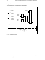
Organization block OB 1 contains the basic structure of the user program.
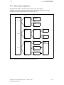
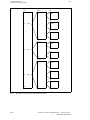
A diagram of this block shows the essential program structures at a glance (Fig. 5.5) and
emphasizes program-interdependent plant sections (Fig. 5.6).
OB 1
PB ”A”
Operating
mode program
JU
PB ”A”
Halt,
emergency
shutdown
BE
FB
Bring to initial
state
BE
BE
PB ”B”
Sequence
control
JU
FB
FB
Sequencer
control
SB
Sequence
step
BE
PB ”B”
BE
BE
PB ”C”
Individual
control level
FB
Group control
BE
SB
Sequence
step
BE
DB
Interface flags
for the
individual
control modules
FB
Unit control
JU
PB ”C”
BE
FB
Unit control
BE
Fig. 5.5
BE
BE
Breakdown of the user program based on the program structure
© Siemens AG 1992 All Rights Reserved
SINUMERIK 840C/880 (PJ)
6FC5197- AA80
5–11
5 Organization Blocks
5.4.2 Basic program organization
OB 1
11.92
PB ”X”
Plant section"X"
FB
Individual
control
BE
JU
FB
Closed-loop
control
PB ”X”
BE
FB
Message
BE
PB ”Y”
Plant section"Y"
BE
FB
Sequence
control
BE
JU
PB ”Y”
FB
Message
BE
PB ”Z”
Plant section"Z"
BE
FB
Closed-loop
control
BE
FB
Arithmetic
JU
PB ”Z”
BE
FB
Logging
BE
Fig. 5.6
5–12
BE
BE
Breakdown of the user program based on the plant structure
© Siemens AG 1992 All Rights Reserved
6FC5197- AA80
SINUMERIK 840C/880 (PJ)
11.92
5.5
5 Organization Blocks
5.5 Programming the interrupt service routine
Programming the interrupt service routine
The PLC 135 WB has interrupt-processing capabilities.
In this mode, the cyclic program is interrupted and an interrupt service routine executed. Once
the interrupt service routine has terminated, the processor returns to the point of interruption
and resumes execution of the cyclic program.
The interrupt service routine is initiated in two different ways:
•
•
I/Os causing interrupts (OB 2)
signal state change of selected input bits (edge-controlled) (OB 3)
Interrupt service routines on the basis of signal status changes (OB 3) allow the user to react
immediately to process signals connected to a maximum of 4 selected input bytes. An edge
change in these signals is thus registered before the process image is updated, thereby
minimizing the response time to time-critical functions in the process.
5.5.1
Interface between operating system and the interrupt service
routine
OB 2 and OB 3 constitute the interface between the operating system and the interrupt service
routines.
Organization block OB 2
OB 2, the block with the highest priority, is called by interrupts of the process I/Os causing the
interrupts. It can only be processed in special mode. The alarms are retained in flag bytes FY 8
to FY 10 and must be acknowledged (reset) by the user.
Organization block OB 3
OB 3 is always invoked when the signal state of a bit in up to four interrupt input bytes
changes. The user may select the input bytes and default it via machine data (PLC MD 124 to
127, see Interface Description Part 1: Signals).
When one of the selected bits changes from "0" to "1" (positive edge) or from "1" to "0"
(negative edge), the interrupt service routine is invoked. The system program calls OB 3,
which contains the user's interrupt service routine.
The system program checks the interrupt bytes every 10 ms (in dependence on MD 155), and
invokes an interrupt service routine when required. OB 3, however, is only processed once per
10 ms scan, even if several signal state changes occur. This means that all the accumulated
edges have to be processed in one pass of OB 3 because they will be overwritten the next
time OB 3 is called.
The type of signal change (positive or negative edge) is entered as transfer parameter in flag
bytes FB 12 to FB 19 (see Interface Description Part 1: Signals). It is not necessary to
acknowledge the interrupts in the flag bytes.
OB 3 can be processed in normal or special mode and has a lower priority than OB 2, i.e.
OB 3 cannot interrupt OB 2.
© Siemens AG 1992 All Rights Reserved
SINUMERIK 840C/880 (PJ)
6FC5197- AA80
5–13
5 Organization Blocks
5.5.2 Timeout in process interrupt processing
5.5.2
12.93
Timeout in process interrupt processing
Timeout with OB 3
If an edge change is detected on an interrupt byte while OB3 is running, the call request for
OB3 is renewed. After OB3 has terminated it is called again.
If the operating system detects that an interrupt has already been entered, it signals a timeout
(FY 6, bit 3). The following then applies:
•
On versions up to SINUMERIK 880, SW6, no distinction is made between a positive edge
and a negative edge. A timeout arises if, for example, a positive and then a negative edge
is detected at a process interrupt input.
•
On SINUMERIK 880 GA2, SW1, and SINUMERIK 840C, a timeout is signalled if a positive
or negative edge is detected at least twice while OB3 is running.
If the PLC MD bit 6048.3 is set when a timeout occurs, the event counter timeout OB 3 (DB 1,
DW 23) is incremented and an OB 3 call is requested again. If the bit is not set, the PLC goes
into the stop state.
Notes:
With the SINUMERIK 880 GA2, SW1, and SINUMERIK 840C the following applies:
•
If several timeouts occur simultaneously within an interrupt byte, no more than one timeout
for the positive edges and one timeout for the negative edges is entered.
•
If several edges occur within an interrupt byte only one timeout is signalled (e.g. two
positive edges).
•
If several positive and several negative edges occur simultaneously within an interrupt byte
with timeout, the event counter timeout OB 3 is incremented by two.
Interrupt-forming I/Os (OB 2)
If an edge change is detected at an interrupt input while OB 2 is running, a new request to call
OB 2 is set. A timeout occurs, if an edge change is detected while OB 2 is running.
5–14
© Siemens AG 1992 All Rights Reserved
6FC5197- AA80
SINUMERIK 840C/880 (PJ)
12.93
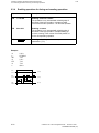
5.6
5 Organization Blocks
5.6 Programming aperiodic processing
Programming aperiodic processing
With organization block OB 4, blocks can be triggered aperiodically. By calling a defined
function macro FB 68 a delay time is started after which OB 4 is called up by the system
program. The function macro is defaulted when called with the desired delay time
(0-32767 ms).
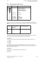
5.7
Programming timed interrupt processing
The processor of the interface control also executes time-controlled processing. Timecontrolled processing is when a signal coming from the "internal clock" causes the processor
in the programmable controller to interrupt "normal" cyclic processing and to process a
specific program.
After processing this program the processor returns to the point of interruption in the lowerpriority program and continues processing (Figs. 5.7 and 5.8).
Note:
Time-controlled processing is not enabled when the system is started up (OB 20), i.e., OB 20
is not interrupted by OB 5, 6 or 7.
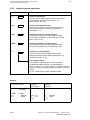
5.7.1 Interface between system program and time-controlled
processing
Organization blocks OB 5, 6 and 7 constitute the interface between system program and timecontrolled processing. Each of these organization blocks is called by the system program in a
defined time grid.
Factors n, m and p can be defined freely by the user within the defined limits and are stored in
PLC MD, 2, 3 and 4 (see INSTALLATION INSTRUCTIONS).
Organization block
Time grid
OB 5
OB 6
OB 7
n . 2.5 ms
m . 10 ms
p . 100 ms
n = 1, 2, 3
m = 1...9
p = 1...255
Organization block OB 5 can only be processed in special mode, OB 6 and 7 can be processed in either normal or special mode.
If several timed interrupts occur simultaneously, interrupt processing is executed with the
priorities specified in Section "Priority assignment for interrupts".
© Siemens AG 1992 All Rights Reserved
SINUMERIK 840C/880 (PJ)
6FC5197- AA80
5–15
5 Organization Blocks
5.7.1 Interface between system program and time-controlled processing
11.92
Example of processing when several alarms occur:
OB 1
PB 17
FB 132
2
JU
1
PB 17
JU
18
13
BE
3
FB 132
11
BE
12
SB 72
5
8
JU
SB 72
BE
6
7
BE
OB 6
4
BE
OB 3
JU
9
FB 8
FB 8
BE
BE
OB 6
10
BE
OB 3
FB 8
15
14
JU
FB 8
BE
16
OB 7
17
JU
PB 73
PB 73
BE
Fig. 5.7
BE
BE
Interrupt-controlled and time-controlled processing (in normal mode) when several interrupts occur
In program block PB 73 is a program part without time-critical response time. It is sufficient if
the inputs and outputs programmed are processed every two seconds. (This programming
method can reduce the average cycle time of the interface control.)
Programming:
OB 7
: JU PB 73
: BE
The call for the program block PB 73 is programmed in organization block OB 7, whereby
20 x 100 ms (p=20) has been selected as time grid for the organization block, so that OB 7 is
processed every 2 seconds. The call can be unconditional or conditional depending on the
previous operations programmed. The organization block is completed with the BE statement.
5–16
© Siemens AG 1992 All Rights Reserved
6FC5197- AA80
SINUMERIK 840C/880 (PJ)
11.92
5 Organization Blocks
5.7.1 Interface between system program and time-controlled processing
OB 1
OB 1
PB 17
FB 132
13
aaaaaaaa
aaaaaaaa
11
12
2
SB 72
18
7
9
OB 3
OB 3
14
OB 3
2
aaaaaa
aaaaaa
4
3
FB 8
17
10
OB 6
16
aaaaaaaa
aaaaaaaa
FB 8
OB 3
15
aaaaaaaa
aaaaaaaa
5
aaaaaaaa
aaaaaaaa
3
aaaaaaaa
aaaaaaaa
8
6
aaaaaaaa
aaaaaaaa
1
FB 132
aaaaaaaa
aaaaaaaa
1
aaaaaaaa
aaaaaaaa
PB 17
OB 6
OB 7
1 Cyclic processing
2 Process alarm processing
3 Timed interrupt processing
Fig. 5.8
Schematic representation of the blocks in the previous example in processing sequence
Legend for Figs. 5.7 and 5.8
1
Start of cyclic processing. The system program calls up organization block OB 1.
2
The timer pulse of the "internal clock" occurs.
3
Block change: The request for the time-controlled program is registered. Cyclic program
processing is interrupted.
4
System program calls up user organization block OB 6 which is to be processed in a 10
ms time frame.
5
After processing the time-controlled program, cyclic program processing is continued.
6
A timer pulse from the "internal clock" occurs.
7
A process interrupt occours: Signals state changes at input 0.4.
8
Block change: The request for the time-controlled and interrupt-controlled program
processing is registered. Cyclic program processing is interrupted.
9
As process interrupt processing of the user program has a higher priority than the timeinterrupt processing, process-interrupt processing is carried out first. The system
program calls up organization block OB 3.
© Siemens AG 1992 All Rights Reserved
SINUMERIK 840C/880 (PJ)
6FC5197- AA80
5–17
aaa
aa
aa
aa
aa
a
5 Organization Blocks
5.7.1 Interface between system program and time-controlled processing
10
12.93
aaaaaaaa
aaaa
After processing of the time-controlled program has been completed, cyclic program
processing is resumed as there is no further alarm.
aaaaaaaa
aaaa
A process interrupt occurs: Signal state change at input 0.3.
aaaaaaaa
aaaa
Block change: The process interrupt is registered; cyclic program processing is
interrupted.
aaaaaaaa
aaaa
The system program calls up organization block OB 3 assigned to input 0.3.
aaaaaaaa
aaaa
A timer pulse of the "internal clock" occurs requesting time-controlled program
processing during processing of the process interrupt.
a
aa
a
a
aa
aa
aa
a
Block change: The request for time-controlled program processing is registered. Process
interrupt processing is not interrupted.
a
aa
a
a
aa
aa
aa
a
After completion of the processing of the interrupt-controlled program, processing of the
time-controlled program is started. The system program calls up OB 7.
a
aa
a
a
aa
aa
aa
a
After the request interrupt has been completely processed, cyclic program processing is
not resumed, as there is still a time-controlled program processing waiting. The system
program calls up organization block OB 6, which is processed in a 10 ms time grid.
As there is no further alarm, cyclic program processing is continued at the point of
interruption.
11
12
13
14
15
16
17
18
Calling non-existent blocks 1)
5.8
Calling a non-existent block
If a user program calls a non-existent (not loaded) block of type PB, SB, FX or OB (OB 180),
the system program calls organization block OB 19 (if present) and continues the interrupted
program without an error message. If OB 19 is not present the call to the non-existent block is
ignored.
The PLC only goes into the stop state with an error message if an non-existent block is called
within the level of OB 19.
When OB 19 is called the type and the number of the missing block is loaded into ACCU1-L
(see Figure).
_______
1)
SINUMERIK 880 GA2, SW 1, and SINUMERIK 840C
5–18
© Siemens AG 1992 All Rights Reserved
6FC5197- AA80
SINUMERIK 840C/880 (PJ)
11.92
5 Organization Blocks
5.8 Calling non-existent blocks
Opening a non-existent data block
When you attempt to open a non-existent (not loaded) block of type DB or DX, the system
program tries to call the organization block OB 19.
If OB 19 is present, the value "0" is entered in the system data "current DB" and "DB length"
(i.e. no data block has been opened). The user program contained in OB 19 is executed and
the interrupted program is continued without an error message.
If OB 19 is not present, the PLC goes into the stop state.
Within the level of the OB 19, the PLC always goes into the stop state with an error message
when an attempt is made to open a non-existent data block.
When OB 19 is called the type and the number of the missing block is loaded into ACCU1-L
(see Figure).
aaaaaaaa
aaaaaaaa
aaaa
aaaaaaaa
aaaaaaaa
aaaaaaaa
aaaaaaaa
aaaaaaaa
aaaaaaaa
aaaaaaaa
aaaaaaaa
aaaaaaaa
aaaaaaaa
aaaaaaaa
aaaaaaaa
aaaaaaaa
aaaaaaaa
aaaaaaaa
aaaaaaaa
aaaaaaaa
aaaaaaaa
aaaaaaaa
aaaaaaaa
aaaaaaaa
aaaaaaaa
aaaaaaaa
aaaaaaaa
aaaaaaaa
aaaaaaaa
aaaaaaaa
aaaaaaaa
aaaaaaaa
aaaaaaaa
aaaaaaaa
aaaaaaaa
aaaaaaaa
aaaaaaaa
aaaaaaaa
aaaaaaaa
Assignment of the ACCU1-L
15 14 13 12 11 10 9
8
7
6
5
4
3
2
1
0
a
a
a
a
a
a
a
a
a
a
a
a
a
a
a
a
a
a
a
a
a
a
a
a
a
a
a
aa
aa
aa
a
a
a
a
a
a
a
a
a
a
a
a
a
a
a
a
a
a
a
a
a
a
a
a
a
a
aa
aa
aa
a
a
a
a
a
a
a
a
a
a
a
a
a
a
a
a
a
a
a
a
a
a
a
a
a
a
a
a
a
a
a
a
a
a
a
a
a
a
a
a
a
a
a
a
a
a
a
a
a
a
a
a
a
a
a
a
a
a
aa
aa
aa
a
a
a
a
a
a
a
a
a
a
a
a
a
a
a
a
a
a
a
a
a
a
a
a
a
a
aa
aa
aa
a
a
a
a
a
a
a
a
a
a
a
a
a
a
a
a
a
a
a
a
a
a
a
a
a
a
a
a
a
a
a
a
a
a
a
a
a
a
a
a
a
a
a
a
a
a
a
a
a
a
a
a
a
a
a
a
a
a
aa
aa
aa
a
a
a
a
a
a
a
a
a
a
a
a
a
a
a
a
a
a
a
a
a
a
a
a
a
a
aa
aa
aa
a
a
a
a
a
a
a
a
a
a
a
a
a
a
a
a
a
a
a
a
a
a
a
a
a
a
aaaa
a
Bit
V
Block type
Block number
V (validity)
0: Block number is valid
1: Block number is invalid (the block number could not be calculated)
Block type
0
0
0
0
0
1
1
0
0
0
0
1
0
0
0
0
1
1
0
0
0
0
1
0
1
0
0
1
:
:
:
:
:
:
:
OB
PB
SB
FB
FX
DB
DX
Notes:
•
If an attempt is made to open a non-existent data block in a high-level language block with
the function HLL_ADB, OB 19 is also called. The PLC goes into the stop state with the
error message 9B. F0004 contains 1.
•
If an attempt is made to open a non-existent data block in a high-level language block with
the function HLL_HLL or with the function HLL_MACRO, the PLC always goes into the
stop state with an error message and OB 19 is not called.
© Siemens AG 1992 All Rights Reserved
SINUMERIK 840C/880 (PJ)
6FC5197- AA80
5–19
12.93
6
6 Start-up
6.1 Self-diagnostics program
Start-up
Starting up of the PLC 135 WB / WB2 / WD is subordinate to the starting up of the numerical
machine tool control (NC). The CPUs of the PLC have subordinate functions.
When the NC branches into the "Start-up mode overall reset" mode a start-up bit is set. In the
NC, deletion and loading of NC and PLC machine data or parameter assignment for the
system program can be executed, with the aid of which start-up of PLC 135 WB / WB2 / WD
is controlled.
Note:
Start-up of the control and the PLC is described in the INSTALLATION INSTRUCTIONS of the
individual controls.
6.1
Self-diagnostics program
After switching on the mains voltage, the interface control runs a self-diagnostics program.
This program tests the most important hardware components and initializes the software
required for system start-up. If errors in the system are recognized, the LED on the front plate
displays the error (Table 6.1 for SINUMERIK 880/880 GA2 and Table 6.2 for SINUMERIK
840C).
LED
Significance (SINUMERIK 880/880 GA2)
continuous (green only)
continuous (red only)
continuous (red and
green)
flashing
once
twice
three times
4 times
5 times
6 times
7 times
8 times
10 times
Cyclic operation
STOP state
GENERAL RESET required (initial power on or data loss)
11 times
12 times
13 times
14 times
15 times
16 times
17 times
18 times
19 times
20 times
Table 6.1
Error with cross-check sum via the system program
Error in the CPU RAM test
Error in timer 0 (process-internal timer) or watchdog error
Error in monitoring test for timeout (880 SW4 only)
Access to link RAM not possible
Error with test access to link RAM
Error in system initialization program
Other PLC failed (if two PLCs are used)
Error of the internal co-processor (COP) register or in the step
address counter (SAZ) creation
Command delegation to word processor (WOP)
Processing of binary commands
Processing of OR, bracket expressions, NOP- or BLD-commands
Processing of block calls and jump commands
Processing of timer and counter operations
Addressing in data memory
Command execution mode
Test address comparator machine code (MC5) and interrupt
processing via co-processor
Monitoring test for timeout with access of the co-processor to the
user memory
ACOP2 not present
LED displays and their meanings for SINUMERIK 880/880 GA2
© Siemens AG
1992 All Rights Reserved
SINUMERIK 840C/880 (PJ)
6FC5197- AA80
6–1
6 Start-up
6.1 Self-diagnostics program
12.93
LEDs for PLC
Significance (SINUMERIK 840C)
continuous (green only)
continuous (red only)
continuous (red and
green)
flashing (red)
once
three times
4 times
5 times
6 times
7 times
Cyclic operation
PLC in STOP state
GENERAL RESET required (initial power on or data loss)
9 times
10 times
11 times
12 times
13 times
14 times
15 times
16 times
17 times
Error with cross-check sum via the system program
Error timer 0 (process-internal timer) or Watch dog error
SW 3: Module is a PLC 135 WB (can no longer be used)
Access to link RAM not possible
Error with test access to link RAM
SW 1 and 2:
Error in system initialization program
(synchronization pattern)
SW 3: No communication with MMC
SW 3: Booting error
ACOP error (group error)
IF PLC cannot be addressed from the PLC
IF PLC RAM defective (program memory or CPU RAM)
Dual Port RAM of IF PLC defective
ADS link to NC defective
ADS link to IF PLC defective
SW 3: ADS link to MMC defective
ADS link (reserved)
LED for IF PLC
Significance
continuous (green only)
continuous (red only)
flashing (red) 12 times
13 times
IF PLC in cyclic operation (no errors), MPC transmission running
IF PLC in STOP state
IF PLC RAM defective (CPU RAM)
Dual Port RAM of IF PLC defective
LED off
No MPC transmission, processor running
Table 6.2
LED displays and their meanings for SINUMERIK 840C
Note:
If the PLC 135 WB2 is used, the LEDs for the PLC and IF PLC are situated on the PLC 135
WB2 or interface PLC module. If the PLC 135 WD is used, all the LEDs are situated on the
front panel of this module.
6–2
© Siemens AG
1992 All Rights Reserved
6FC5197- AA80
SINUMERIK 840C/880 (PJ)
11.92
6.2
6 Start-up
6.2 System initialization program
System initialization program
After the self-diagnostics program has run, the system initialization program is called.
In its first section, the data required for running the organization program are set up. This
setting up includes:
•
•
•
•
•
•
Stack organization,
Segmentation for word processor and co-processor,
Entries in the location-dependent CPU interrupt table,
Task priority lists,
Setting up task data and
Initialization of counts and periodic values.
In the second section the system initialization program defines the type of start up after
switching on the mains voltage. The following points are checked:
•
•
•
•
•
•
Whether the switch-on test pattern is missing (i.e. data lost)
Whether there is a battery interrupt
If the setting-up bit is set
Request from the NC "automatic warm restart after setting-up overall reset"
STOZUS operating status bit set (acquisition of interrupt event or continuation of the
STOP state, see Section "Memory Allocation and Organization")
Cold restart or warm restart attempt aborted.
If the STOZUS identifier is set, the control remains in the STOP state.
If, in the second section, (testing of run-up after switching on the mains voltage) the STOZUS
identifier is not set, but one of the other conditions is fullfilled, an automatic cold restart is
executed; a warm restart of the control only occurs if none of the mentioned conditions are
fulfilled.
Overall reset with subsequent bootstrapping of the user memory (URLOE = 1) is always
required
•
•
If first start-up is instigated,
Data loss occured by removing the PLC CPU from the central controller or with power
failure simutaneous battery voltage failure.
If the mains voltage fails during active processing checks, the processing checks are aborted
by the programmer. The system initialization program instigates the cold restart.
© Siemens AG 1992 All Rights Reserved
SINUMERIK 840C/880 (PJ)
6FC5197- AA80
6–3
6 Start-up
6.3 User data blocks
6.3
12.93
User data blocks
On each cold restart, certain data blocks are set up and written in ascending order into the
user data segment. A list of these data blocks is contained in the INTERFACE DESCRIPTION
PART 1: SIGNALS of the control concerned.
Data blocks DB 30 to DB 71 are defaulted with 0. The channel, spindle and axes data blocks
are defaulted with the user data if they are enabled for writing (see INTERFACE DESCRIPTION, PART 1: SIGNALS).
A warm restart has the same initialization as a cold restart except that
•
•
User machine data (DB 62, DB 65) and
Setting data (DB 68, DB 71)
are not defaulted with 0, but retain their values.
Note:
The decoding blocks for the NC channels (DB 80 and higher) are not set up or initialized by
the system.
6.4
Timeout analysis
A write access of the PLC to the communication or local bus is executed independently by the
bus interface. Write accesses are acknowledged immediately, and the PLC program can continue (Buffered access to communication/local bus). If a timeout occurs during such an access
the current state of the registers of the processor and co-processor give no information as to
the cause of the timeout.
The user can switch off buffered accesses to the communication and local bus (e.g. to test
STEP 5 programs during the installation phase) via machine data (PLC operating system MD
bit 6049.0). These accesses are then slower because the processor only receives an
acknowledgement when the whole bus cycle has finished.
Machine data 6049.0 must be set in order to be able to determine the exact cause of a
timeout.
6–4
© Siemens AG 1992 All Rights Reserved
6FC5197- AA80
SINUMERIK 840C/880 (PJ)
11.92
7
7 Device Error Analysis
7.1 Interrupt stack
Device Error Analysis
The system program can ascertain faulty operation of the central processor, errors in the
system program or the effect of erroneous programming.
If the interpreter ascertains an error in command execution or if another error occurs causing
program interruption, a branch is made into the STOP loop.
7.1
Interrupt stack
The programmer's ”Output ISTACK” function can be invoked to help analyze errors. This
function displays the control bits.
CONTROL BITS
NB
NB
BSTSCH
SCHTAE
ADRBAU
SPABBR
NAUAS
NB
NB
NB
NNN
NB
NB
NB
NB
NB
STOZUS STOANZ NEUSTA
WIEDAN
BATPUF
URLAD
BARB
BARBEND
KEINPS
UAFEHL MAFEHL
EOVH
NB
NB
OBWIED NB
NB
NB
NB
NB
PADRFE
ASPLUE RAMADFE
EAADFE SYNFEH NINEU
NIWIED
RUFBST
NB
SUMF
URLOE
NB
NB
STS
STP
NB
NB
NB
NB
NB
NB
NB
NB
NB
NB
NB
NB
KOPFNI
The control bits in detail:
NB
BSTSCH
SCHTAE
ADRBAU
SPABBR
NAUAS
NNN
STOZUS
STOANZ
NEUSTA
WIEDAN
BATPUF
URLAD
Not used
Coordination bit for block shift
Memory compression facility active
Successful address table generation following cold/warm restart
Memory compression aborted
Decentralized mains power failure
Illegal OP-code/invalid command parameter
PLC in STOP mode (may be set/reset by OS only)
STOP status flag
Cold restart flag
Warm restart flag
Power supply unit is battery-backed
Copying the user program data was aborted
© Siemens AG 1992 All Rights Reserved
SINUMERIK 840C/880 (PJ)
6FC5197- AA80
7–1
7 Device Error Analysis
7.1 Interrupt stack
BARB
BARBEND
KEINPS
UAFEHL
MAFEHL
EOVH
OBWIED
KOPFNI
PADFRE
ASPLUE
RAMADFE
EAADFE
SYNFEH
NINEU
NIWIED
RUFBST
SUMF
URLOE
STS
STP
7–2
11.92
Processing check test function active
STOP state caused by abortion of processing check test function
No user program memory or user data memory submodule
STOP status due to interrupt event
Restart error flag (PLC could not go into normal operation)
Input bytes available for process alarms (four successive inputs)
Organization block for warm restart (OB20) active
Block header in user memory cannot be interpreted
Bad EPROM
User memory addressing not contiguous
Bad RAM
Error in I/O area
Invalid block length in user memory or bad block synchronization word
No cold restart possible (bootstrapping required)
No warm restart possible (cold restart required)
Non-existent block called
Sumcheck error
Overall reset and subsequent bootstrap loading of user memory required
Direct STOP initiated via STS
Interrupt condition code following STP
© Siemens AG 1992 All Rights Reserved
6FC5197- AA80
SINUMERIK 840C/880 (PJ)
12.93
7 Device Error Analysis
7.1 Interrupt stack
The following can be called to screen as the next display:
PLC INFORMATION
DEPTH:
ISTACK
01
BEF-REG: 13E0
SAZ:
35F3A
BST-STP: 00004
XX-NR.r:
38
AKT
REL-SAZ: 0004A
OB-NR.:
1
BEF-Z:
ACCU1: 76B1 0000 ACCU2: 0000 E45C
RESULT COND. COD.: ANZ1
ANZ0
X
STATUS VKE
X
DB-ADR: 065F0
DB-NR.:
23
DBL-REG:
99
CAUSE OF FAULT:
BR-ADR:
YY-NR.:
BEF-Z:
368A2
1
ERR CODE: 0079 0000 0120 0000
OVFL
OVFLS ODER ERAB
X
KB
KDB
TRAF
SUF
STUEB STUEU
NAU
QVZ
ADF
ZYK
WEFE
PEU
DEPTH
The last interrupt event (DEPTH = 01) is always shown for the PLC 135 WB
BEF-REG
OP code and parameters of instruction being content of the step address
counter, points to the next instruction
SAZ
Content of the stop address counter points to the address of the next command
DB-ADR
Block start address
BR-ADR
specifies the block return address, i.e. the address at which processing of a
block is resumed when the current block has been exited. This address is in the
calling block.
BST-STP
Block stack pointer
XX-NR.
Current block whose execution was initiated by the interrupt
DB-NR.
Current data block (DB or DX)
YY-NR.
Block that called the current block (XX)
AKTOB-NR. Current processing level 9999 is displayed, if no processing level is active
REL-SAZ
Relative step address counter in the current block
DBL-REG
Register containing the data block length (DB or DX)
BEF-Z
Instruction pointer (for high-level language blocks), see description of high-level
language blocks
ERR CODE Error number as in address F0000 (error coding)
© Siemens AG 1992 All Rights Reserved
SINUMERIK 840C/880 (PJ)
6FC5197- AA80
7–3
7 Device Error Analysis
7.1 Interrupt stack
12.93
See Section EVENT FLAGS OF THE PLC 135 WB/WB2/WD for the meaning of the result
condition codes.
KB
Invocation of a non-existent block
KDB
Invocation of a non-existent block
TRAF
Transfer error
SUF
Substitution error
STUEB
Block stack overflow (maximum 64 entries possible)
STUEU
Interrupt stack overflow (maximum 7 levels possible)
NAU
Mains power failure (controller remains in the STOP mode until power is
recovered)
QVZ
Timeout
ADF
Adressing error
ZYK
Cycle scan time exceeded
WEFE
Group flag for runtime error of a time-controlled program
PEU
I/Os not ready (in the expansion unit)
7–4
© Siemens AG 1992 All Rights Reserved
6FC5197- AA80
SINUMERIK 840C/880 (PJ)
12.93
7 Device Error Analysis
7.2 Detailed error code
7.2
Detailed error code
Using the programmer's info function, the user can display additional information for interrupt
analysis by entering pseudo address F0000hex.
The following is displayed on the programmer screen:
Up to SINUMERIK 880, SW 6
ADR
WERT
ADR
WERT
ADR
WERT
ADR
WERT
F0000 00xx
F0001 xxx1
F0002 xxx2
F0003 xxx3
F0004 zob2
F0005 zob3
F0006 zob4
F0007 zob5
F0008 zob6
F0009 zob7
F000A 0000
F000B 0000
F000C 0000
F000D 0000
F000E 0000
F000F 0000
F0010 0000
F0011 0000
F0012 0000
F0013 * * * *
F0014 * * * *
F0015 * * * *
F0016 * * * *
....
SINUMERIK 880 GA2, SW 1, and SINUMERIK 840C
ADR
WERT
ADR
WERT
ADR
WERT
ADR
WERT
F0000 00xx
F0001 xxx1
F0002 xxx2
F0003 xxx3
F0004 xxx4
F0005 * * * *
F0006 * * * *
F0007 * * * *
F0008 * * * *
F0009 * * * *
F000A 0000
F000B 0000
F000C 0000
F000D 0000
F000E 0000
F000F 0000
F0010 0000
F0011 0000
F0012 0000
F0013 * * * *
F0014 * * * *
F0015 * * * *
F0016 * * * *
....
Addresses F000C to F0012 are described in detail in Section ”Block lists”, the displays ”* * * *”
are irrelevant.
The following applies to addresses F0000 to F0009:
xx
=
Internal detailed error code (ERRCODE)
xxx1
xxx2
xxx3
xxx4
=
=
=
=
Auxiliary error info, word 1
Auxiliary error info, word 2
Auxiliary error info, word 3
Auxiliary error info, word 4 1)
_______
1)
SINUMERIK 880 GA2, SW 1, and SINUMERIK 840C
© Siemens AG 1992 All Rights Reserved
SINUMERIK 840C/880 (PJ)
6FC5197- AA80
7–5
7 Device Error Analysis
7.2 Detailed error code
zob2
zob3
zob4
zob5
zob6
zob7
=
=
=
=
=
=
12.93
Event counter, processing timeout in OB 2 2)
Event counter, processing timeout in OB 3 2)
Event counter, processing timeout in OB 4 2)
Event counter, processing timeout in OB 5 2)
Event counter, processing timeout in OB 6 2)
Event counter, processing timeout in OB 7 2)
Event counter timeout
The "Event counters, timeout in OB 2 to OB 7" show how many requests for interrupt
processing were lost while an interrupt-controlled program was being processed (see the
Section "Timeout in process interrupt processing").
The number of the organization block which caused the delay is entered in word 1 (xxx1) of
the auxiliary error info.
Note:
On the SINUMERIK 880 GA2, SW1 and higher and SINUMERIK 840C and higher, the "event
counters, timeout" were removed from the pseudoaddresses F0004 to F0009 and put into the
diagnostics DB (DB 1, DW 22 to DW 27). Flags F0005 to F0009.
Supplementary error data
The auxiliary error info enables more precise analysis of the reason for a timeout or parameter
initialization error. All auxiliary error info is deleted on a cold restart.
The opcode of the instruction that generated the timeout is stored in word 1 (xxx1).
Words 2 and 3 (xxx2, xxx3) contain the following:
•
Timeout caused by LIR, TIR, TNB or TNW:
xxx2
Offset address and
xxx3
Segment number of the non-addressed memory
•
Timeout caused by substitution operations:
xxx2
Substitution operation
•
Timeout caused by LPB, LPW, TPB, TPW operations:
xxx2
= 000E (Timeout during loading of the input modules)
= 000A (Timeout during transport to the output modules)
xxx3 = Byte address (BCD coded) of the operation parameter
Note:
•
•
On the SINUMERIK 880 GA2, SW1 and higher and SINUMERIK 840C and higher, the
detailed error code (F0000) and the supplementary error data (F0001 to F0004) are also
stored in the diagnostics DB (DB 1, DW 160 to DW 164).
The error messages of the detailed error code (ERRCODE) are listed in the
INSTALLATION INSTRUCTIONS of the control concerned.
_______
2)
7–6
Up to and including SINUMERIK 880, SW 6
© Siemens AG 1992 All Rights Reserved
6FC5197- AA80
SINUMERIK 840C/880 (PJ)
12.93
8 Memory Allocation and Organization
8.1 Segment allocation
8
Memory Allocation and Organization
8.1
Segment allocation
The expanded memory area of the PLC 135 WB/WB2/WD interface control can be addressed
directly with the new programmer software. The segment switch is no longer required.
The following address areas can be selected:
Segment
SYDSEG
AWDSEG
Addresses
AWPSEG
Segment
switch
Error
identifier
Programmer initial
address/effective address
for:
SINUMERIK 880
00000/00000 06000/0C000 30000/60000 E0000/---
F0000/---
SINUMERIK 880 GA2
00000/00000 06000/0C000 30000/60000 E0000/---
F0000/---
SINUMERIK 840C SW1
and 2
00000/00000 06000/0C000 30000/60000 E0000/---
F0000/---
SINUMERIK 840C SW3
00000/00000 08000/10000 30000/60000 E0000/---
F0000/---
Because the programmer addresses are word-oriented addresses, the programmer address is
the effective address divided by two.
The segment switch is now only required when reading in blocks and in the function SPAUS.
© Siemens AG 1992 All Rights Reserved
SINUMERIK 840C/880 (PJ)
6FC5197- AA80
8–1
8 Memory Allocation and Organization
8.1 Segment allocation
12.93
Memory allocation
Segment number
System data memory
48 KByte
51) or 62)
User data memory part 1
16 KByte
61) or 92)
User data memory part 2
32 KByte
User program memory 1
64 KByte
a
a
a
a
a
a
a
a
a
a
a
a
a
a
a
a
a
a
a
a
a
a
a
a
a
a
a
a
a
aa
aa
aa
aa
a
a
a
a
a
a
a
a
a
a
a
a
a
a
a
a
a
a
a
a
a
a
a
a
a
a
a
a
a
a
a
a
a
a
aa
aa
aa
aa
a
1
91) or 52)
10
User program memory 2
64 KByte
11
User program memory 3
64 KByte
12
User program memory 4
64 KByte
7
System program
128 KByte
memory
8
Fig. 8.1
Memory allocation in the PLC 135 WB/WB2 interface control
_______
1)
2)
8–2
SINUMERIK 880, SW 6
Up to and including SINUMERIK 880, SW 4
© Siemens AG 1992 All Rights Reserved
6FC5197- AA80
SINUMERIK 840C/880 (PJ)
12.93
8 Memory Allocation and Organization
8.1 Segment allocation
Memory allocation
1
System data memory
64 KByte
User data memory
64 KByte
User program memory 1
64 KByte
aaaaaaaaaa
aaaaaaaaaa
5 and 6
9
10
User program memory 2
64 KByte
11
User program memory 3
64 KByte
12
User program memory 4
64 KByte
7
System program
128 KByte
memory
8
Table 8.2
Memory allocation in the PLC 135 WD interface control
© Siemens AG 1992 All Rights Reserved
SINUMERIK 840C/880 (PJ)
6FC5197- AA80
8–3
8 Memory Allocation and Organization
8.2 Segment switch
11.92
8.2
Segment switch
8.2.1
Changing the segment switch
The following sequence applies to the PG 685 programmer:
•
•
•
•
•
Call the information functions with the F5 key
Call any memory areas with the F1 key
Enter the pseudo-address E0000hex
Press the Enter key
Press the Abort key
The first word shown is the current setting of the segment switch.
•
•
Press the correction key
Enter the new segment address
8.2.2
Processing data blocks with the segment switch
By setting the segment switch you can choose between the user program memory the target
segment of data blocks (DB, DX). If the segment switch is set to AWDSEG, i.e. the content of
address E0000hex = 0006, all data blocks inputs from the programmer go to the user data
memory.
If the segment switch has another content, i.e. the content of address E0000hex is not equal
to 0006 (AWPSEG), all blocks go to the user program memory.
For reasons of compatibility, the value 0006H applies to the user data memory on SINUMERIK
880, software version 6 and higher.
Data blocks, created using the FB11 (EINR-DB) always go to the user data memory.
However, data blocks of FB11 also go to the user program memory on editing if the segment
switch is not set to 0006.
Data blocks created using FB11 or edited using the programmer can be edited or erased and
can be controlled with a programmer using STEUERN VAR. The initial address of a data block
changes when it is read in or compressed.
8.3
Block lists
The start addresses of the block lists can be output by entering pseudo-address F0000hex (see
Section ”Detailed error code” for the significance of addresses F0000 to F0009):
F000C
F000D
F000E
F000F
F0010
F0011
F0012
8–4
Start address of the OB block list
Start address of the FB block list
Start address of the DB block list
Start address of the FX block list
Start address of the SB block list
Start address of the PB block list
Start address of the DX block list
© Siemens AG 1992 All Rights Reserved
6FC5197- AA80
SINUMERIK 840C/880 (PJ)
11.92
8 Memory Allocation and Organization
8.3 Block lists
The following should be observed with regard to output of the block lists via the address list:
•
The first address of the address list entry is the offset address; the second one is the
segment address.
•
High and low bytes are interchanged in the specified address.
•
The offset addresses are word-oriented, except that the enteries of the DB list are byteoriented; these must be divided by two after the high/low swap.
It is important to observe the internal structure of the block list for direct processing of the
block list using the instructions LIR and TIR on versions SINUMERIK 880, SW6 and higher and
SINUMERIK 840C and higher.
Structure of a block list entry
Bit
15
14
13
12
11
10
9
8
7
6
5
4
3
2
1
0
Offset address
Segment address
D:
0:
1:
M/H:
00:
MC5 block
otherwise: HLL block
D
M/H
Data block not write-protected
Data block write-protected
The identification bits 0 to 11 have to be masked for address processing.
© Siemens AG 1992 All Rights Reserved
SINUMERIK 840C/880 (PJ)
6FC5197- AA80
8–5
11.92
9 STEP 5 Operation Set with Programming Examples
9.1 General notes
9
STEP 5 Operation Set with Programming
Examples
9.1
General notes
The STEP 5 operation set is subdivided into basic operations and supplementary operations.
The basic operations are intended for the execution of simple binary functions. As a rule, they
can be input/output in the three methods of representation (LAD,CSF and STL) of the STEP 5
language on the programmer.
The supplementary operations are intended for complex functions (e.g. control, signalling and
logging); they cannot be represented graphically and can only be input/output in the statement
list (STL) on the programmer.
Most of the STEP 5 operations use two registers (each 32 bits wide) as the source for the
operands and as the destination for the results: Accumulator 1 (ACCU 1) and Accumulator 2
(ACCU 2). Since these registers are not always used or affected in their full width, they are
subdivided into smaller units for the following descriptions, as shown below:
Bit significance:
231 ... 216
ACCU-H
215 ... 20
ACCU-L
Load and transfer commands use the contents of ACCU 1 as follows, depending on the
addressing (byte, word or double word-oriented):
Byte by byte: ACCU 1-L,
Bit 27 to 20
Transfer
Addressed byte
Load
Word by word: ACCU 1-L,
Addressed word
Double word by double
word: ACCU 1-L+H
Addressed double word
For load operations, the bit positions of ACCU 1 which are not involved are always filled with
zeros. For all load commands, the content of the address is first loaded in ACCU 1. For
transfer commands, ACCU 1 and ACCU 2 remain unchanged.
9.1.1
Numeric representation
Numbers in different types of representation are allowed as operands for the STEP 5
commands which operate on or change or compare the contents of ACCU 1 and ACCU 2.
Depending on the operation to be executed, the content of ACCU 1 or ACCU 2 is interpreted
as one of the following representations:
•
Fixed-point number:
+ 0...+ 32 767
– 1... – 32 768
The fixed-point number is located in ACCU L and is interpreted as a 16-bit binary number
in two's complement representation.
© Siemens AG 1992 All Rights Reserved
SINUMERIK 840C/880 (PJ)
6FC5197- AA80
9–1
9 STEP 5 Operation Set with Programming Examples
9.1.1 Numeric representation
11.92
•
Fixed-point double-word:
0 ...
+2 147 483 647
– 1 ...
– 2 147 483 648
The fixed-point double-word is located in the ACCU and is interpreted as a 32-bit binary
number in two's complement representation.
•
Floating-point number: m . 2exp
m = Mantissa
exp = Exponent
±0.1 701 412 · 1039
±0.1 469 368 · 10-38
The floating-point number is represented as follows in the ACCU (exception: see
"Arithmetic operations"):
Bit significance :
231 ... 224
223 ... 20
Sign +exp
Sign + m
The exponent is an 8-bit binary number in two's complement representation:
–128 exp < 127
The mantissa is 24 bits wide and normalized:
0.5 positive mantissa < 1
–1 < negative mantissa –0.5
•
BCD word-coded number with sign and 3 digits:
Assignments in ACCU L
Bit significance: 215...212
Sign
211...28
27...24
102
101
23...20
100
The individual numbers are positive 4-bit binary numbers in two's complement
representation.
Sign:
•
0000 if the number is positive
1111 if the number is negative
BCD double word-coded number with sign and 7 digits:
Assignments in the ACCU
Bit significance: 231...228
Sign
219...216
104
227...224
223...220
106
105
215...212
211...28
103
102
27...24
23...20
101
100
Note:
This internal representation need not comply with the format in which the numbers are
entered via the programmer when creating a program. The programmer generates the above
representations.
9–2
© Siemens AG 1992 All Rights Reserved
6FC5197- AA80
SINUMERIK 840C/880 (PJ)
12.93
9 STEP 5 Operation Set with Programming Examples
9.1.2 Condition codes of the PLC 135 WB/WB2/WD
9.1.2
Condition codes of the PLC 135 WB/WB2/WD
There are commands for processing individual bit information, and there are commands for
processing word information (8, 16 or 32 bits). In both groups, there are commands which set
condition codes and commands which interpret condition codes. For both command groups
there are "condition codes for bit operations" and "condition codes for word operations". The
CC byte for the PLC 135 is as follows:
27
CC for word operations
CC 1
CC 0
OV
20
CC for bit operations
OR
OS
RLO
ER
Condition codes for bit operations:
ER:
ER signifies first interrogation. This is the start of a logic operation. ER is set at the end
of a logic operation sequence (memory operations).
RLO: Result of logic operation; result of binary operations. Logical value for comparison
commands.
OR:
This informs the processor that the following AND operations must be handled before
an OR operation (AND before OR).
Condition codes for word operations:
OV:
OVER; this indicates whether, for the arithmetic operation just terminated, the valid
numeric range has been exceeded.
OS:
OVER LATCHING; in the course of two or more arithimetic operations, the overflow
memory bit serves to indicate whether an overflow error (OVER) has occurred at some
time. The bit OS is reset on end-of-block.
CC 1, CC 0 are condition codes whose interpretation can be found in the following table.
Condition codes
0
0
0
Fixed-point
calculation:
Result
Result = 0
0
1
0
Result < 0
-
ACCU2 < ACCU1
-
1
0
0
Result > 0
0
ACCU2 > ACCU1
1
0
0
1
”Over-Null 1)”
-
-
-
0
1
1
0 from pos. range
-
-
-
1
0
1
0 from neg. range
-
-
-
1
1
1
Division by zero
-
-
-
CC 1
CC 0
OVER
Boolean:
result
nis0
Comparison:
Contents of
ACCU1 + ACCU 2
ACCU2 = ACCU1
Shift:
shifted bit
0
Floating-point
calculation:
Result
Mantissa=0;
Exp. allowed
Mantissa <0;
Exp. allowed
Mantissa >0;
Exp. allowed
Mantissa=0;
Exp.=–128
Mantissa <0;
Exp.=+127
Mantissa >0;
Exp.=+127
Division by zero
Jump operations are available for immediate interpretation of the condition codes (see Section
"Supplementary operations").
_______
1)
Special case: Greatest negative number added to itself
© Siemens AG 1992 All Rights Reserved
SINUMERIK 840C/880 (PJ)
6FC5197- AA80
9–3
9 STEP 5 Operation Set with Programming Examples
9.2 Basic operations
9.2
11.92
Basic operations
Basic operations are programmable in program, sequence, organization and function blocks.
They can be input and output in program, sequence and organization blocks in the three
methods of representation (LAD, CSF and STL). In the function blocks, the operations are only
displayed in the statement list.
Exceptions:
1. Load, transfer and code operations can only be programmed graphically, indirectly and
with limits in conjunction with timing and counting operations.
2. Arithmetic operations and the Stop command (STL) can only be programmed in a
statement list.
9.2.1
Logic operations, binary
Operation
Parameter
Function
)
Right parenthesis
A(
O(
O
AND operation with parenthesized expressions
OR operation with parenthesized expressions
OR operation on AND functions
A
O
AND operation with:
OR operation with:
I
Q
F
0.0 to 127.7
0.0 to 127.7
0.0 to 255.7
Scanning an input for logic 1
Scanning an output for logic 1
Scanning a flag for logic 1
D
0.0 to 255.15
Scanning data for logic 1
N I
N Q
0.0 to 127.7
0.0 to 127.7
Scanning an input for logic 0
Scanning an output for logic 0
N F
N D
T
N T
0.0 to 255.7
0.0 to 255.15
0 to 255
0 to 255
Scanning a flag for logic 0
Scanning data for logic 0
Scanning a timer for logic 1
Scanning a timer for logic 0
C
N C
0 to 255
0 to 255
Scanning a counter for contents >0
Scanning a counter for contents=0
Binary logic operations produce the "RLO" (result of the logic operation).
At the beginning of a logic sequence, the result depends only on the type of operation
(A =AND, AN = AND NOT, O = OR, ON = OR NOT) and the scanned logic level. Within a
logic sequence, the RLO is formed from the type of operation, previous RLO and scanned
logic level. A logic sequence is terminated by a limited-step command (e.g. storage
operations).
9–4
© Siemens AG 1992 All Rights Reserved
6FC5197- AA80
SINUMERIK 840C/880 (PJ)
11.92
9 STEP 5 Operation Set with Programming Examples
9.2.1 Logic operations, binary
AND operation
Given circuit
Control system
list
flowchart
A
A
A
=
I 1.1 1.3 1.7
I1.1
I1.3
&
STEP 5 representation
Statement
Ladder diagram
I
I
I
Q
1.1
1.3
1.7
3.5
I1.1
I1.3
I1.7
Q3.5
I1.1
&
I1.3
I1.7
Q3.5
I1.7
Q3.5
Q 3.5
A logic 1 appears at output Q 3.5 if all inputs are simultaneously at logic 1. A logic 0 appears
at output Q 3.5 if at least one of the inputs is at logic 0.
The number of scans and the order of programming are arbitrary.
OR operation
Given circuit
STEP 5 representation
Statement
list
I 1.2 1.7 1.5
I1.2
I1.7
I1.5
O
O
O
=
1
I
I
I
Q
1.2
1.7
1.5
3.2
Ladder diagram
I1.2
Control system
flowchart
Q3.2
I1.2
>=1
I1.7
I1.7
I1.5
Q3.2
I1.5
Q3.2
Q 3.2
A logic 1 appears at output Q 3.2 if at least one of the inputs is at logic 1. A logic 0 appears
at output Q 3.2 if all inputs are simultaneously at logic 0.
The number of scans and the order of programming are arbitrary.
© Siemens AG 1992 All Rights Reserved
SINUMERIK 840C/880 (PJ)
6FC5197- AA80
9–5
9 STEP 5 Operation Set with Programming Examples
9.2.1 Logic operations, binary
11.92
AND before OR operation
Given circuit
I1.5
I1.6
I1.4
&
I1.3
&
I1.5
I1.4
I1.6
I1.3
STEP 5 representation
Statement
Ladder diagram
Control system
list
flowchart
A
A
O
A
A
=
I
I
I1.5
1.5
1.6
I1.4
I1.6
Q3.1
I1.5
&
I1.6
I1.3
I 1.4
I 1.3
Q 3.1
I1.4
>=1
&
Q3.1
I1.3
Q 3.1
1
Q 3.1
A logic 1 appears at output Q 3.1 if at least one AND condition is fulfilled. A logic 0 appears at
output Q 3.1 if no AND condition is fulfilled.
OR before AND operation
Given circuit
STEP 5 representation
Statement
list
I6.0
I6.1
I6.2
I6.3
I6.0
I6.2
>=1
I6.1
&
I6.3
O
O
A
A(
O
O
)
=
Ladder diagram
I
6.0
I6.0
I
6.1
I6.2
Q2.1
I6.1
Control system
flowchart
>=1
I6.0
I6.1
I6.2
I
I
6.2
6.3
I6.3
&
>=1
I6.3
Q3.1
Q 2.1
1
Q2.1
Q2.1
A logic 1 appears at output Q 2.1 if input I 6.0 or input I 6.1 and one of inputs I 6.2 and I 6.3 at
logic 1. A logic 0 appears at output Q 2.1 if input I 6.0 is at logic 0 and the AND condition is
not fulfilled.
9–6
© Siemens AG 1992 All Rights Reserved
6FC5197- AA80
SINUMERIK 840C/880 (PJ)
12.93
9 STEP 5 Operation Set with Programming Examples
9.2.1 Logic operations, binary
OR before AND operation
Given circuit
I1.4
I1.5
I2.0
1
1
I1.5
I2.0
I2.1
Control system
list
flowchart
A(
O
O
)
A(
O
O
)
=
I2.1
I1.4
STEP 5 representation
Statement
Ladder diagram
Q 3.0
&
I
I
1.4
1.5
I
I
2.0
2.1
I1.4
I2.0
I1.5
I2.1
Q3.0
I1.4
1
I1.5
&
I2.0
1
Q3.0
I2.1
Q 3.0
Q 3.0
A logic 1 appears at output Q 3.0 if both OR conditions are fulfilled. A logic 0 appears at output
Q 3.0 if at least one OR condition is not fulfilled.
Scanning for logic 0
Given circuit
I1.5
I1.6
STEP 5 representation
Statement
Ladder diagram
Control system
list
flowchart
A
I 1,5
AN I 1.6
=
Q 3.0
I1.5
I1.6
Q3.0
I1.5
I1.6
&
Q3.0
&
Q3.0
Q3.0
A logic 1 only appears at output Q 3.0 if input I 1.5 is at logic 1 (N/O contact closed) and input
I 1.6 is at logic 0 (N/C contact not opened).
9.2.2
Storage operations
Operation
Parameter
S
R
=
Function
Set
Reset
Assign
I
Q
F
D
0.0 to 127.7
0.0 to 127.7
0.0 to 255.7
0.0 to 255.15
© Siemens AG 1992 All Rights Reserved
SINUMERIK 840C/880 (PJ)
an input
an output
a flag
a data word
6FC5197- AA80
9–7
9 STEP 5 Operation Set with Programming Examples
9.2.2 Storage operations
11.92
RS flipflop for latching signal output
Given circuit
I1.4
I2.7
R
I1.4
I2.7
S
1 1
1 0
STEP 5 representation
Statement
Ladder diagram
Control system
list
flowchart
A
S
A
R
I
Q
I
Q
2.7
3.5
1.4
3.5
I2.7
I1.4
Q3.5
Q3.5
S
I2.7
S
RQ
I1.4
RQ
Q3.5
Q3.5
A logic 1 at input I 2.7 causes the flipflop to be set. If the logic level at input I 2.7 changes to
0, this state is retained, i.e. the signal is stored. A logic 1 at input 1.4 causes the flipflop to be
reset. If the logic level at input I 1.4 changes to 0, this state is retained.
If the set signal (input I 2.7) and reset signal (input I 1.4) are applied simultaneously, the last
programmed scan (AI 1.4 in this case) is effective during processing of the rest of the
program.
RS flipflop with flags
Given circuit
I1.3
I2.6
R
I1.3
I2.6
S
1 1
1 0
STEP 5 representation
Statement
Ladder diagram
Control system
list
flowchart
A
S
A
R
I
F
I
F
2.6
1.7
1.3
1.7
I2.6
I1.3
F1.7
F1.7
S
I2.6
S
RQ
I1.3
RQ
F1.7
F1.7
A logic 1 at input I 2.6 causes the flipflop to be set. If the logic level at input I 2.6 changes to
0, this state is retained, i.e. the signal is stored. A logic 1 at input 1.3 causes the flipflop to be
reset. If the logic level at input I 1.3 changes to 0, this state is retained.
If the set signal (input I 2.6) and reset signal (input I 1.3) are applied simultaneously, the last
programmed scan (AI 1.3 in this case) is effective during processing of the rest of the
program.
9–8
© Siemens AG 1992 All Rights Reserved
6FC5197- AA80
SINUMERIK 840C/880 (PJ)
11.92
9 STEP 5 Operation Set with Programming Examples
9.2.2 Storage operations
Simulation of a momentary-contact relay
Given circuit
STEP 5 representation
Statement
Ladder diagram
Control system
list
I1.7
A
AN
=
A
S
AN
R
I1.7
F4.0
F2.0
F2.0
flowchart
I
F
F
F
F
I
F
1.7
4.0
2.0
2.0
4.0
1.7
4.0
I1.7
F4.0
F2.0
F4.0
I1.7
S
F4.0
R
&
F2.0
S
I1.7
Q
R
Q
The AND condition (A I 1.7 and AN F 4.0) is fulfilled with each leading edge of input I 1.7; flags
F 4.0 ("signal edge flag") and F 2.0 are set when RLO = 1.
With the next processing cycle, the AND condition A I 1.7 and AN F 4.0 are not fulfilled
because flag F 4.0 has been set. Flag F 2.0 is reset. Flag F 2.0 is therefore at logic 1 during a
single program run.
Binary scaler (trigger circuit)
Given circuit
STEP 5 representation
Statement
Ladder diagram
list
I1.0
F1.0
I1.0
F1.1
Q3.0
F2.0
Q3.0
0
I1.0
Q3.0
A
AN
=
A
S
AN
R
A
A
=
A
AN
AN
S
A
R
I
F
F
F
F
I
F
F
Q
F
F
Q
F
Q
F
Q
1.0
1.0
1.1
1.1
1.0
1.0
1.0
1.1
3.0
2.0
1.1
3.0
2.0
3.0
2.0
3.0
I1.0
F1.1
F1.0
Control system
flowchart
F1.1
I1.0
S
R Q
Q3.0
F1.1
Q3.0
F1.1
F1.0
I1.0
F1.1
&
F1.0
F1.0
F1.1
S
I1.0
R Q
F2.0
F2.0
Q3.0
S
F2.0
F1.1
&
Q3.0
F2.0
R Q
F1.1
&
Q3.0
Q3.0
F2.0
S
F2.0
R Q
The binary scaler (output Q 3.0) changes its logic state with each change of logic level from 0
to 1 (leading edge) of input I 1.0. Half the input frequency therefore appears at the output of
the flipflop.
© Siemens AG 1992 All Rights Reserved
SINUMERIK 840C/880 (PJ)
6FC5197- AA80
9–9
9 STEP 5 Operation Set with Programming Examples
9.2.3 Load and transfer operations
9.2.3
11.92
Load and transfer operations
Operation
Parameter
L
T
Functions
Load
Transfer
I B
I W
I D
Q B
Q W
Q D
F B
F W
F D
D R
D L
D W
D D
T 1)
C 1)
P Y
0 to 127
0 to 126
0 to 124
0 to 127
0 to 126
0 to 124
0 to 225
0 to 254
0 to 252
0 to 255
0 to 255
0 to 255
0 to 254
0 to 255
0 to 255
0 to 127
128 to 255
P W 4)
0 to 126
128 to 254
K
K
K
K
M 1)
H 1)
F 1)
Y 1)
K B 1)
K S 1)
K G 1)
K T 1)
K C 1)
16-bit pattern
0 to FFFFH
–32768 to +32767
0 to 255 for
each byte
0 to 255
2 alpha
characters
± 0.1469368 . 10-38
to
± 0.1701412 . 10+39
0.0 to 999.3
0 to 999
an input byte from PII 2)
an input word from the PII 2)
an input double word from the PII 2)
an output byte from the PIQ 3)
an output word from the PIQ 3)
an output double word from the PIQ 3)
a flag byte
a flag word
a flag double word
an item of data (right byte)
an item of data (left byte)
a data word
a data double word
a time (binary)
a count (binary)
an I/O byte of the digital inputs/outputs
with process image
an I/O byte of the digital or analog
inputs/outputs without process image
an I/O word of the digital inputs/outputs
with process image
an I/O word of the digital or analog
inputs/outputs without process image
a constant as bit pattern
a constant in hex code
a constant as fixed-point number
a constant, 2 bytes
a constant, 1 byte
a constant, 2 ASCII characters
a constant as floating-point number
a time (constant)
a count (constant)
The load and transfer operations are unconditional commands, i.e. they are executed
irrespective of the result of the logic operation. The load and transfer operations can only be
graphically programmed indirectly in conjunction with time or counting operations, otherwise
only in statement lists.
_______
1)
2)
3)
4)
Not for transfers
PII: Process input image
PIQ: Process output image
Only even parameters are allowed; error NNP is signalled for odd parameters.
9–10
© Siemens AG 1992 All Rights Reserved
6FC5197- AA80
SINUMERIK 840C/880 (PJ)
11.92
9 STEP 5 Operation Set with Programming Examples
9.2.3 Load and transfer operations
Example: Load and transfer function
(DR 5)
DW 5
(DL 5)
L DD 5
DW 6
ACCU1-H
ACCU1-L
(DW 5)
T DW 10
(DW 6)
(DW 6)
ACCU2-H
ACCU2-L
DW 10
FB 0
aaaaaaaaaaaaaaaa
aaaaaaaaaaaaaaaa
0
(FB0)
ACCU1-H
ACCU1-L
(DW 5)
ACCU1-H
ACCU1-L
ACCU2-H
ACCU2-L
(DW 6)
FB 25
FB 26
FB 27
FB 28
IB 5
IB 6
a
a
a
a
a
a
a
a
a
a
a
a
a
a
a
a
aa
aa
a
a
a
a
a
a
aaa
a
L IW 5
0
0
(IB5)
(IB6)
0
0
a
a
a
aa
a
a
aa
aa
a
0
0
0
(FB0)
0
aaaaaa
aaaaaa
aaaaaa
aaa
0
T FD 25
a
a
a
aa
aa
aa
aa
a
a
aa
aa
aa
aa
aa
a
a
a
a
a
a
a
a
aa
aa
a
aaaaaa
aaaaaa
aaaaaa
aaa
aaaaaa
aaa
L FB 0
0
(FB0)
ACCU2-H
ACCU2-L
T QB 54
QB 54
(EB 6)
Loading and transferring a time (also timing and counting operations)
Given circuit
STEP 5 representation
Statement
Ladder diagram
list
T10
Load
A
L
SP
T
I 5.0
IW 22
T 10
QW 64
Control system
flowchart
T10
T10
I5.0
1
IW22
TW
R
DU
DE
Q
QW64
I 5.0
1
IW22
TW
R
DU
DE
Q
QW64
Transfer
AW64
With graphic input, QW 64 was assigned to output DU of the timer. The programmer then
automatically inserts the appropriate load and transfer command in the user program. Thus the
contents of the memory location addressed with T 10 are loaded into the accumulator
(ACCU 1).
The accumulator contents (ACCU 1) are then transferred to the process image addressed with
QW 64.
© Siemens AG 1992 All Rights Reserved
SINUMERIK 840C/880 (PJ)
6FC5197- AA80
9–11
9 STEP 5 Operation Set with Programming Examples
9.2.4 Timing and counting operations
9.2.4
11.92
Timing and counting operations
In order to load a timer or counter with a set command, the value must be loaded in the
accumulator beforehand.
The following load operations are expedient: 1)
For timer: L KT, L IW, L QW, L FW, L DW
For counter: L KC, L IW, L QW, L FW, L DW
Operation
Parameter
Function
SP
SE
SD
SF
SF
R
S
R
CU
CD
0 to 255
0 to 255
0 to 255
0 to 255
0 to 255
0 to 255
0 to 255
0 to 255
0 to 255
0 to 255
Start a timer as a pulse
Start a timer as an extended pulse
Start a timer as an ON-delay
Start a timer as a latching ON-delay
Start a timer as an OFF-delay
Reset a timer
Set a counter
Reset a counter
Up counting
Down counting
T
T
T
T
T
T
C
C
C
C
Only parameters 0 to 255 are permitted. If a parameter with a higher number is programmed
the interpreter outputs error NNP.
Notes:
•
•
Since the timer and counter commands are supported by LAD/ACOP, and the latter has no
parameter check, it is possible for the signal edge flags to be affected by timers or
counters which are not programmed in this command.
Up to and including SINUMERIK 880, software version 5, up to 128 timers and counters
are possible.
Example:
As a result of a DO FW command, command SD T0 (substituted SD T 129) is to be
processed. With RLO = 0: Bits ZWG, ZKS, FMS with T 1 are deleted.
_______
1)
Timing or counting operations do not change the contents of ACCU 1.
9–12
© Siemens AG 1992 All Rights Reserved
6FC5197- AA80
SINUMERIK 840C/880 (PJ)
11.92
9 STEP 5 Operation Set with Programming Examples
9.2.4 Timing and counting operations
Pulse
Given circuit
I3.0
S
10s
1
Control system
list
flowchart
A
L
SP
A
=
I3.0
R
STEP 5 representation
Statement
Ladder diagram
I 3.0
KT 10.2
T 1
T 1
Q 4.0
T1
T10
I3.0
1
I 3.0
1
DU
DU
10.2
TW
10.2
TW
DE
R
Q
DE
T1
T1
Q4.0
Q
Q4.0
Q4.0
Q4.0
With the first execution, the timer is started if the result of the logic operation is 1. If execution
is repeated with RLO = 1, the timer is unchanged. If the RLO = 0 the timer is set to zero
(cleared).
Scans A T and O T result in a logic 1 as long as the timer is still running.
DU and DE are digital outputs of the timer. The time is present with the timebase, binarycoded at output DU and BCD-coded at output DE.
I3.0
Q4.0
T
KT 10.2:
The specified value (10) is loaded in the timer. The number to the right of the point specifies
the timebase:
0 = 0.01 s
1 = 0.1 s
2=1s
3 = 10 s
© Siemens AG 1992 All Rights Reserved
SINUMERIK 840C/880 (PJ)
6FC5197- AA80
9–13
9 STEP 5 Operation Set with Programming Examples
9.2.4 Timing and counting operations
11.92
Extended pulse
Given circuit
STEP 5 representation
Statement
Ladder diagramn
Control system
list
flowchart
I3.1
T2
A
L
SE
A
=
I3.1
R
S
T2
T2
1
I 3.1
IW15
T 2
T 2
Q 4.1
T2
I3.1
1
V
I 3.1
1
V
DU
DU
IW15
TW
IW15
TW
DE
R
Q
DE
T2
Q4.1
Q4.1
R
Q
Q4.1
Q4.1
With first execution, the timer is started if the result of the logic operation is 1. If the RLO = 0
the timer is unchanged.
Scans AT or OT result in a logic 1 as long as the timer is still running.
Byte 15
I3.1
Q4.1
T
T
54
Timebase
3
Byte 16
7
4
10 2 10 1
3
0
Bit number
10 0
Time
IW 15:
Setting the time with the value of operands I, Q, F or D present in BCD code (input word 15 in
the example).
9–14
© Siemens AG 1992 All Rights Reserved
6FC5197- AA80
SINUMERIK 840C/880 (PJ)
11.92
9 STEP 5 Operation Set with Programming Examples
9.2.4 Timing and counting operations
ON-delay
Given circuit
STEP 5 representation
Statement
Ladder diagram
Control system
list
flowchart
I3.5
R
S
9s
0
T3
A
L
SD
A
=
I3.5
I 3.5
KT 9.2
T 3
T 3
Q 4.2
T3
I3.5
T
0
T
0
DU
DU
K9.2
K9.2
TW
TW
DE
R
Q
DE
T3
T3
Q4.2
R
Q4.2
I 3.5
Q
Q4.2
Q4.2
With the first execution, the timer is started if the result of the logic operation is 1. If execution
is repeated and the RLO = 1, the timer is unchanged. If the RLO = 0 the timer is set to zero
(cleared).
Scans A T or O T result in a logic 1 if the time has elapsed and the result of the logic
operation is still present at the input.
I3.5
Q4.2
T
KT 9.2:
The specified value (9) is loaded in the timer.
The number to the right of the point specifies the timebase:
0 = 0.01 s
1 = 0.1 s
2=1s
3 = 10 s
© Siemens AG 1992 All Rights Reserved
SINUMERIK 840C/880 (PJ)
6FC5197- AA80
9–15
9 STEP 5 Operation Set with Programming Examples
9.2.4 Timing and counting operations
11.92
OFF-delay
Given circuit
I3.4
0
S
t
Control system
list
flowchart
AN
L
SF
A
=
I3.4
R
STEP 5 representation
Statement
Ladder diagram
I3.4
T5
I 3.4
FW13
T 5
T 5
Q 4.4
T5
I3.4
0
T
I 3.4
0
T
DU
DU
FW13
TW
FW13
TW
DE
R
Q
DE
T5
T5
Q4.1
R
Q4.4
Q
Q4.4
Q4.4
With the first execution, the timer is started if the result of the logic operation is 0. If execution
is repeated and the RLO = 0, the timer is unchanged. If the RLO = 1 the timer is set to zero
(cleared).
Scans AT and OT result in a logic 1 if the time is still running or the RLO is still present at the
input.
Byte 13
I3.4
Q4.4
T
T
54
Timebase
3
Byte 14
0
7
4
10 2 10 1
3
0
Bit number
10 0
Time
FW 13:
Setting of the time with the value of operands I, Q F or D present in BCD code (flag word 13 in
the example).
9–16
© Siemens AG 1992 All Rights Reserved
6FC5197- AA80
SINUMERIK 840C/880 (PJ)
11.92
9 STEP 5 Operation Set with Programming Examples
9.2.4 Timing and counting operations
Latching ON-delay
Given circuit
I3.2
STEP 5 representation
Statement
Ladder diagram
Control system
list
flowchart
I3.3
A
L
SS
A
R
A
=
I3.3
R
S
20s
T4
0
I3.2
T4
T4
T4
I 3.3
DW21
T 4
I 3.2
T 4
T 4
Q 4.3
T4
I3.3
T
s
I 3.3
T
s
DU
DU
DW21
DW21
TW
TW
DE
R
Q
DE
Q4.3
I3.2
R
Q
I3.2
Q4.3
Q4.3
Q4.3
With the first execution, the timer is started if the result of the logic operation is 1. If the
RLO = 0, the timer is unchanged. Scans A T and O T result in a logic 1 if the time has
elapsed.
The logic level only goes to 0 when the timer has been reset with function RT.
DW21
T
T
54
Timebase
3
0
7
4
10 2 10 1
3
0
Bit number
10 0
Time
DW 21:
Setting the time with the value of operands I, Q, F or D present in BCD code (data word 21 in
the example).
© Siemens AG 1992 All Rights Reserved
SINUMERIK 840C/880 (PJ)
6FC5197- AA80
9–17
9 STEP 5 Operation Set with Programming Examples
9.2.4 Timing and counting operations
11.92
Setting a counter
Given circuit
I4.1
R
S
IW20
STEP 5 representation
Statement
Ladder diagram
Control system
list
flowchart
A
L
S
CI
C1
I 4.1
IW20
C 1
C1
CU
CU
CD
CD
I4.1
S
+
CQ
Binary
16 bits
IW20
CV
I4.1
DU
IW20
S
CV
DE
R
DU
DE
R
Q
Q
With the first execution, the counter is set if the result of the logic operation is 1. If execution is
repeated, the counter is unchanged (irrespectively of whether the RLO is 1 or 0). With
repeated first execution with RLO = 1, the counter is set again (signal edge decoding). DU
and DE are digital outputs of the counter. The count is present in binary code at output DU,
and BCD-coded at output DE.
The flag required for signal edge decoding of the set input is also present in the count word.
Byte 20
3
Byte 21
0
7
4
10 2 10 1
3
0
10 0
Time
IW 20:
Setting a counter with the value of operands I, Q, F or D present in BCD code (input word 20
in the example).
9–18
© Siemens AG 1992 All Rights Reserved
6FC5197- AA80
SINUMERIK 840C/880 (PJ)
11.92
9 STEP 5 Operation Set with Programming Examples
9.2.4 Timing and counting operations
Resetting a counter
Given circuit
Control system
list
flowchart
C1
I4.2
R
STEP 5 representation
Statement
Ladder diagram
S
A
R
A
=
CI
I
C
C
Q
4.2
1
1
2.4
= 0
CQ
CU
CD
CD
S
S
CV
IW20
Binary
16 bits
C1
CU
CV
DU
DU
DE
DE
Q2.4
I4.2
Q2.4
R
Q
R
I4.2
Q
Q2.4
If the result of the logic operation is 1 the counter is set to zero (cleared).
If the result of the logic operation is 0 the counter is unchanged.
Up counting
Given circuit
STEP 5 representation
Statement
Ladder diagram
list
C1
I4.1
A
I 4.1
CU C 1
R
S
CI
+
CQ
Binary
16 bits
Control system
flowchart
C1
I4.1
CU
CU
CD
CD
S
S
CV
DU
CV
DE
R
Q
DU
DE
R
Q
The value of the addressed counter is incremented by 1. Function CU (count up) is only
executed with a positive-going edge (from 0 to 1) of the logic operation programmed before
CU. The flags required for signal edge decoding of the count inputs are also contained in the
count word.
A counter with two different inputs can be used as an up or down counter by means of the two
separate signal edge flags for CU (count up) and CD (count down).
© Siemens AG 1992 All Rights Reserved
SINUMERIK 840C/880 (PJ)
6FC5197- AA80
9–19
9 STEP 5 Operation Set with Programming Examples
9.2.4 Timing and counting operations
11.92
Down counting
Given circuit
STEP 5 representation
Statement
Ladder diagram
Control system
list
flowchart
C1
I4.0
A
I 4.0
CD C 1
R
I4.0
S
CI
-
CQ
I4.0
CD
CU
CU
S
S
CV
Binary
16 bits
C1
CD
DU
CV
DE
R
DU
DE
Q
R
Q
The value of the addressed counter is decremented by 1. The function only becomes effective
with a positive-going edge (from 0 to 1) of the logic operation programmed before CD. The
flags required for signal edge decoding of the count inputs are also in the count word.
A counter with two different inputs can be used as an up or down counter by means of the two
separate signal edge flags for CU (count up) and CD (count down).
9.2.5
Comparison operations
The comparison operations compare the content of Accumulator 1 with the content of
Accumulator 2. The values to be compared must therefore first be stored in the accumulators,
e.g. with load operations. The accumulator contents remain unchanged during the comparison.
Operation
!=
><
>
>=
<
<=
(none)
F
G
D
9–20
Parameter
Function
Compare for equal
Compare for not equal
Compare for greater
Compare for greater than or equal to
Compare for less
Compare for less than or equal to
Two fixed-point numbers
Two floating-point numbers
Two fixed-point double-word numbers
© Siemens AG 1992 All Rights Reserved
6FC5197- AA80
SINUMERIK 840C/880 (PJ)
11.92
9 STEP 5 Operation Set with Programming Examples
9.2.5 Comparison operations
Compare for equal
Given circuit
IB19
STEP 5 representation
Statement
Ladder diagram
Control system
list
flowchart
IB20
C1
L
L
!=
=
C2
IB19
IB20
F
Q 3.0
IB19
C1
F
IB19
C1
!=
F
!=
Q3.0
IB20
C2
Q
C2
IB20
Q
Q3.0
Q3.0
The operand first specified is compared with the next operand according to the comparison
function. The comparison results in a binary result of the logic operation.
RLO = 1: Comparison is fulfilled, ACCU 1-L = ACCU 2-L
RLO = 0: Comparison is not fulfilled, ACCU 1-L ACCU 2-L
ACCU 2-H and ACCU 1-H are not involved in the operation with the fixed point comparison.
The numeric representation of the operands (fixed-point calculation) has to be considered in
programming the comparison operation.
0
IB19
ACCU 2-L
0
IB19
ACCU 1-L
Compare for not equal
Given circuit
STEP 5 representation
Statement
list
IB21
IB22
C1
L
L
><
=
C2
Ladder diagram
IB21
DW3
F
Q 3.1
IB21
C1
Control system
flowchart
IB19
F
C1
F
><
><
Q3.1
DW3
C2
Q
DW3
C2
Q
Q3.0
Q3.1
The operand first specified is compared with the next operand according to the comparison
function. The comparison results in a binary result of the logic operation.
RLO = 1: Comparison is fulfilled, ACCU 1-L ACCU 2-L
RLO = 0: Comparison is not fulfilled, ACCU 1-L = ACCU 2-L
ACCU 2-H and ACCU 1-H are not involved in the operation with the fixed point comparison.
The numeric representation of the operands (fixed-point calculation in this case) has to be
considered in programming the comparison operation.
0
IB21
DW3
ACCU 2-L
ACCU 1-L
© Siemens AG 1992 All Rights Reserved
SINUMERIK 840C/880 (PJ)
6FC5197- AA80
9–21
9 STEP 5 Operation Set with Programming Examples
9.2.5 Comparison operations
11.92
Compare for greater
Given circuit
IW3
STEP 5 representation
Statement
Ladder diagram
Control system
list
flowchart
FD5
C1
L
L
>
=
C2
>
<
IW3
FD5
D
Q 3.2
IW3
D
IW3
C1
>
D
>
Q3.2
FD5
>
C1
C2
Q
C2
FD5
Q
Q3.2
<
Q3.2
The operand first specified is compared with the next operand according to the comparison
function. The comparison results in a binary result of the logic operation.
RLO = 1: Comparison is fulfilled, ACCU 2 > ACCU 1
RLO = 0: Comparison is not fulfilled, ACCU 2 ACCU 1
ACCU2-H
0
0
IB3
IB4
ACCU2-L
ACCU1-H
FB5
FB6
FB7
FB8
ACCU1-L
The numeric representation of the operands has to be considered in programming the
comparison operation. The contents of ACCU 1 and ACCU 2 are interpreted as fixed-point
numbers with double-word width.
Compare for less
Given circuit
STEP 5 representation
Statement
list
DD2
Ladder diagram
Control system
flowchart
IB7
C1
L
L
<
=
C2
>
<
DD2
IB7
D
Q 3.4
DD2
DD2
D
C1
D
<
<
Q3.4
IB7
>
C1
C2
Q
IB7
C2
Q
Q3.4
<
Q3.4
The operand first specified is compared with the next operand according to the comparison
function. The comparison results in a binary result of the logic operation.
RLO = 1: Comparison is fulfilled, ACCU 2 < ACCU 1
RLO = 0: Comparison is not fulfilled, ACCU 2 ACCU 1
ACCU2-H
ACCU1-H
DW2
0
ACCU2-L
DW3
0
0
IB7
ACCU1-L
The numeric representation of the operands has to be considered in programming the
comparison. The contents of ACCU 1 and ACCU 2 are interpreted as fixed-point numbers
with double-word width.
9–22
© Siemens AG 1992 All Rights Reserved
6FC5197- AA80
SINUMERIK 840C/880 (PJ)
11.92
9 STEP 5 Operation Set with Programming Examples
9.2.5 Comparison operations
Compare for greater than or equal to
Given circuit
DD10
DD20
C1
C2
STEP 5 representation
Statement
Ladder diagram
list
L
DD10
L
DD20
>=G
=
>
<
DD10
G
DD10
C1
>=
G
>
Q3.3
DD20
>
C1
Control system
flowchart
C2
Q
C2
DD20
Q
Q3.3
<
Q3.3
The operand first specified is compared with the next operand according to the comparison
function. The comparison results in a binary result of the logic operation.
RLO = 1: Comparison is fulfilled, ACCU 2 ACCU 1
RLO = 0: Comparison is not fulfilled, ACCU 2 < ACCU 1
ACCU2-H
DW10
DW11
ACCU2-L
ACCU1-H
DW20
DW21
ACCU1-L
The numeric representation of the operands has to be considered in programming the
comparison operation. The contents of ACCU 1 and ACCU 2 are interpreted as a floatingpoint number.
Compare for less than or equal to
Given circuit
STEP 5 representation
Statement
list
DD2
Ladder diagram
Control system
flowchart
IB7
C1
L
L
<
=
C2
>
<
DD2
DD4
G
Q 3.4
DD2
DD2
D
C1
D
<
<
Q3.4
DD4
>
C1
C2
Q
IB7
C2
Q
Q3.4
<
Q3.4
The operand first specified is compared with the next operand according to the comparison
function. The comparison results in a binary result of the logic operation.
RLO = 1: Comparison is fulfilled, ACCU 2 ACCU 1
RLO = 0: Comparison is not fulfilled, ACCU 2 > ACCU 1
ACCU2-H
DW1
DW2
ACCU2-L
ACCU1-H
DW4
DW5
ACCU1-L
The numeric representation of the operands has to be considered in programming the
comparison operation. The contents of ACCU 1 and ACCU 2 are interpreted as a floatingpoint number.
© Siemens AG 1992 All Rights Reserved
SINUMERIK 840C/880 (PJ)
6FC5197- AA80
9–23
9 STEP 5 Operation Set with Programming Examples
9.2.6 Block calls
9.2.6
11.92
Block calls
Operation
Parameter
Function
0 to 255
0 to 255
0 to 255
180
Unconditional jump
Conditional jump
(depending on the RLO)
to a program block
to a function block (type FB)
to a sequence block
to an organization block OB 180
F X
0 to 255
Unconditional jump
Conditional jump
(depending on the RLO)
to a function block (type FX)
D B
D X
2 to 255
2 to 255
Data block call
DX data block call
JU
JC
P
F
S
O
B
B
B
B
DO
DOC
C
CX
BE
BEC
BEU
Block end
Block end, conditional (depending on RLO)
Block end, unconditional
Command C DB and CX DX (data block call) is explained under "Calling data blocks"
(see Section ”Data blocks”).
Commands BE (block end) and BEC (block end, conditional) result in a return to the calling
block. Command BE must be programmed at the end of each data block (except for DB, DX).
Example:
PB 7
PB 20
AF15.1
AI 20.0
JU PB20
BEC
BE
BE
If the result of the logic operation is 1, the return to PB7 already takes place with processing of
the BEC command.
If the result of the logic operation is not equal to 0, processing of PB20 continues up to the BE
command, which then initiates the return to PB7 when PB20 has been fully processed.
9–24
© Siemens AG 1992 All Rights Reserved
6FC5197- AA80
SINUMERIK 840C/880 (PJ)
11.92
9 STEP 5 Operation Set with Programming Examples
9.2.6 Block calls
Unconditional call for a function block
Given circuit
PB 101
FB 72
.
.
.
.
.
.
JU
.
.
.
.
FB72
STEP 5 representation
StatementLadder diagram
Control system
list
flowchart
.
.
.
JU FB 72
.
.
.
FB 72
FB 72
.
.
.
.
.
.
BE
BE
The unconditional function block call is entered at the desired program point. With graphic
methods of representation LAD and CSF, the called block (FB, FX) is represented as a box.
Conditional call for a program block
Given circuit
PB 135
Control system
list
flowchart
FB 83
.
.
.
JC
STEP 5 representation
StatementLadder diagram
.
.
.
.
.
.
.
FB83
.
.
.
BE
.
.
.
.
.
.
JC FB83
.
.
.
FB 83
FB 83
BE
At the desired program point, the conditional block call is entered after the appropriate logic
operation. If the result of the logic operation is 1, a jump to the specified block takes place. If
the condition is not fulfilled, the jump is not executed. With graphic methods of representation
LAD and CSF, the called block is represented as a box.
© Siemens AG 1992 All Rights Reserved
SINUMERIK 840C/880 (PJ)
6FC5197- AA80
9–25
9 STEP 5 Operation Set with Programming Examples
9.2.7 Code operations
9.2.7
11.92
Code operations
The code operations allow a time or count, which is present in binary from, to be loaded as a
code in the accumulator; the corresponding value is still available in BCD form for further
processing.
Operation
Parameter
LC
Function
Load as code
T
C
0 to 255
0 to 255
times
counts
Loading a time (coded)
Given circuit
STEP 5 representation
StatementLadder diagram
list
T10
Load
A
L
SP
LC
T
I 5.0
IW 22
T 10
T 10
QW50
Control system
flowchart
T10
T10
I5.0
1
IW22
CV
R
DU
DE
Q
I 5.0
1
IW22
CV
QW50
R
DU
DE
Q
QW50
Transfer
QW50
The content of the memory location addressed with T 10 is loaded coded into the accumulator.
The subsequent transfer operation transfers the content from the accumulator to the memory
location of the process images addressed with QW50. With the graphic methods of
representation LAD and CSF a coding operation can only take place indirectly as a result of
the assignment of output DE of a timer or counter. With method of representation STL,
however, this command can be isolated.
9–26
© Siemens AG 1992 All Rights Reserved
6FC5197- AA80
SINUMERIK 840C/880 (PJ)
11.92
9 STEP 5 Operation Set with Programming Examples
9.2.8 Arithmetic operations
9.2.8
Arithmetic operations
Arithmetic operations can only be represented in the statement list.
They process the contents of Accumulators 1 and 2. Suitable load operations, for example, are
required.
Operation
+
x
:
Parameter
Function
(none)
Addition
Subtraction
Multiplication
Division
F
G
of two fixed-point numbers
of two floating-point numbers
By means of two load operations, ACCU 1 and ACCU 2 can be loaded according to the
operands of the load operations. Arithmetic operations can then be executed with the contents
of both accumulators.
Example:
ACCU1
L
ACCU2
IW 1
IW1
L
IW 2
IW2
F
IW1
IW1–IW2=Result
ACCU1
IW1
The subsequent transfer operation transfers the result stored in ACCU 1 to the operand issued
for the transfer operation. If, during calculation with fixed-point numbers, an overflow occurs
(OV = 1) ACCU 1-H is cleared.
In the multiplication and division of floating-point numbers, only a 16-bit mantissa is used for
the calculation. The result is reduced precision:
Multiplication:
Division:
At least 12 bits of the mantissa are exact
At least 11 bits of the mantissa are exact
In the subtraction of floating-point numbers, Bit 24 may be incorrect if the difference between
the two exponents is greater than 24.
© Siemens AG 1992 All Rights Reserved
SINUMERIK 840C/880 (PJ)
6FC5197- AA80
9–27
9 STEP 5 Operation Set with Programming Examples
9.2.9 Other operations
9.2.9
11.92
Other operations
The following operations can only be represented in a statement list.
Operation
STP
NOP 0
NOP 1
BLD
Parameter
Function
0 to 255
Stop
No operation (all bits cleared)
No operation (all bits set)
Screen command
The STOP command is used, for example, when the PLC is required to go to the stop state in
the event of certain critical states of the system or when a device error occurs.
The no-operations serve, for example, for keeping memory locations free or overwriting them.
The screen command governs the subdivision of progam parts into segments within a block. It
is automatically stored in the program by the programmer and is treated as a no-operation by
the interface controller.
9.3
Supplementary operations (FBs, FXs only)
Function blocks can be programmed with an operation set which is extended compared to the
program blocks. The full operation set for function blocks comprises the basic operations and
the supplementary operations.
With the function blocks, the operations are only represented in a statement list. The programs
of the function blocks therefore cannot be programmed in graphic form (CSF or LAD).
Described in the following are the supplementary operations. Possibilities of combination of the
substitution commands with the actual operands are also given.
9–28
© Siemens AG 1992 All Rights Reserved
6FC5197- AA80
SINUMERIK 840C/880 (PJ)
11.92
9 STEP 5 Operation Set with Programming Examples
9.3.1 Logic operations, binary
9.3.1
Logic operations, binary
Operation
Description
A =
AND function to test a formal operand for logic 1
AN=
AND function to test a formal operand for logic 0
O =
OR function to test a formal operand for logic 1
ON=
OR function to test a formal operand for logic 0
Insert formal operand
The actual operands allowed are binary addressed inputs,
outputs and flags (parameters: I, O; parameter type DI) as
well as timers and counters (parameters T, C).
Example:
:A
: AN
: AN
:O
:=
=
=
=
=
=
9.3.2
ON
STOP
END
AMNT
RUN
Setting operations
Operation
Description
S =
Set (binary) a formal operand
RB=
Reset (binary) a formal operand
==
Assign the result of the logic operation to a formal
operand
Insert formal operand
The actual operands allowed are binary addressed inputs,
outputs and flags (parameters: I, Q; parameter type DI).
Example:
:A
: RB
:A
:S
=
=
=
=
I0.7
MSP
TIME
MSP
MSP
I0.7
TIME
R
S
© Siemens AG 1992 All Rights Reserved
SINUMERIK 840C/880 (PJ)
6FC5197- AA80
9–29
9 STEP 5 Operation Set with Programming Examples
9.3.3 Timing and counting operations
9.3.3
12.93
Timing and counting operations
Operation
Description
RD=
Reset (digital) a formal operand
(parameters: T,C)
SP=
Start a time, preset as formal operand, with the value
stored in the accumulator as a pulse
(parameter: T)
SR=
Start a time, preset as formal operand, with the value
stored in the accumulator as an on-delay
(parameter: T)
SEC=
Start a time, preset as formal operand, with the value
stored in the accumulator as an extended pulse; or
set a counter, preset as formal operand, with the
following, specified count
(parameters: T, C)
SSV=
Start a time, preset as formal operand, with the value
stored in the accumulator as a latching on delay, or
up-counting of a counter specified as formal operand
(parameters: T, C)
SFD=
Start a time, preset as formal operand, with the value
stored in the accumulator as an off-delay, or
down-counting of a counter preset as formal operand
(parameters: T, C)
Insert formal operand
The actual operands allowed are timers and counters;
exception: Timers only with SP and SR.
The time or count can be specified as follows, as for the
basic operations or as a formal operand:
Set the time or count with the value present in BCD code
of operands IW, QW, FW, DW (parameters: I; parameter
type: W) specified as formal operands, or as data
(parameter: D; parameter type: KT, KC).
Notes:
The following timers and counters are available to the user:
SINUMERIK 880 SW3 and 4:
SINUMERIK 880 GA2, SW1/840C:
9–30
128 timers, 128 counters
255 timers, 255 counters
© Siemens AG 1992 All Rights Reserved
6FC5197- AA80
SINUMERIK 840C/880 (PJ)
11.92
9 STEP 5 Operation Set with Programming Examples
9.3.3 Timing and counting operations
Examples:
Function block call
NAME
ANNA
BERT
JACK
: JU FB203
: EXAMPLE
:
I 10.3
:
T 17
:
Q 18.4
NAME
MAXI
IRMA
EVA
DORA
EMMA
: JU FB204
: EXAMPLE
:
I 10.5
:
I 10.6
:
I 10.7
:
C 15
:
F 58.3
NAME
CURT
CARL
PETE
CUTE
: JU FB205
: EXAMPLE
:
I 10.4
:
T 18
:
IW20
:
F 100.7
Program in
function block
Program
executed
:A
:L
: SSU
:A
:=
= ANNA
KT 010.2
= BERT
= BERT
= JACK
:A
:L
: SS
:A
:=
I 10.3
KT 010.2
T 17
T 17
Q 18.4
:A
: SSU
:A
: SFD
:A
:L
: SEC
: AN
:=
= MAXI
= DORA
= IRMA
= DORA
= EVA
KZ100
= DORA
= DORA
= EMMA
:A
: CU
:A
: CD
:A
:L
:S
: AN
:=
I 10.5
C 15
I 10.6
C 15
I 10.7
KC100
C 15
C 15
F 58.3
:A
:L
: SEC
:=
= CURT
= PETE
= CARL
= CUTE
:A
:L
: SE
:=
I 10.4
IW20
T 18
F 100.7
© Siemens AG 1992 All Rights Reserved
SINUMERIK 840C/880 (PJ)
6FC5197- AA80
9–31
9 STEP 5 Operation Set with Programming Examples
9.3.4 Enabling operations for timing and counting operations
9.3.4
11.92
Enabling operations for timing and counting operations
Operation
Description
FR
T 0 to 255
Enabling a time for a restart
The operation is only executed with a leading edge of
the result of the logic operation. It initiates a restart
of the time if the RLO present is 1 for the start operation.
FR
C0 to 255
Enabling a counter
The operation is only executed with a leading edge of
the result of the logic operation. It initiates setting, up
or down counting of the counter if the RLO present is 1
for the corresponding operation.
FR=
Enabling a formal operand a restart,
parameters (T, C)
Example:
:A
:L
: SP
:A
: FR
:A
:=
I 10.0
KT 500.0
T 10
I 10.1
T 10
T 10
Q 2.0
RLO
for SP T
(I 10.0)
RLO
for FR
(I 10.1)
t
Scan
with AT
9–32
t
(Q 2.0)
© Siemens AG 1992 All Rights Reserved
6FC5197- AA80
SINUMERIK 840C/880 (PJ)
11.92
9 STEP 5 Operation Set with Programming Examples
9.3.5 Bit test operations (FB, FX only)
9.3.5
Bit test operations (FB, FX only)
Operation
Parameter
TB
TBN
SU
RU
Function
Test the bit for logic 1
Test the bit for logic 2
Set bit unconditionally
Reset bit unconditionally
I
0.0 to 127.7
an input
Q
0.0 to 127.7
an output
F
C
T
D
0.0 to 255.7
0.0 to 255.15
0.0 to 255.15
0.0 to 255.15
a flag
a count word
a time word
a data word
Operations "P" and "PN" are scans. They test a bit of the operand specified in the following,
and then insert the result of the logic operation irrespective of previous scans and the previous
status.
Operation
Logic level of the bit
in the specified
operand
Result of logic operation
TB
0
1
0
1
0
1
1
0
TBN
The RLO formed in this way can be subjected to further logic operations. However, a bit test
operation must always be positioned at the beginning of a logic operation.
1st example:
The logic level of the 10th bit of data word 205 is ANDed with the logic level of input I 13.7.
:C
: TB
:A
:=
DB 200
D 205.10
I 13.7
F 210.3
Operations "SU" and "RU" are executed independently of the result of the logic operation.
When this operation has been processed, the addressed bit in the specified operand is set to
logic 1 (for SU) or logic 0 (for RU).
2nd example:
The third bit is to be set by DW 55 and the 9th bit by DW 103.
: SU D 55.3
: RU D 103.9
© Siemens AG 1992 All Rights Reserved
SINUMERIK 840C/880 (PJ)
6FC5197- AA80
9–33
9 STEP 5 Operation Set with Programming Examples
9.3.6 Load and transfer operations
9.3.6
11.92
Load and transfer operations
Operation
Description
L =
Load a formal operand
The value of the operand specified as a formal operand
will be loaded into the ACCU (parameters: I, Q;
parameter type: BY W, D).
LD=
Load a formal operand as code
The value of the timer or counter specified as a formal
operand will be loaded into the ACCU in BCD form
(parameters: T, C).
LW=
Load the bit pattern of a formal operand
The bit pattern of the formal operand will be loaded
into the ACCU (parameter : D; parameter type: KF, KH,
KM, KY, KS, KT, KC).
LDW=
Load the bit pattern of a formal operand
The bit pattern of the formal operand will be loaded
into the ACCU (parameter: D; parameter type: KG).
T =
Transfer to a formal operand
The accumulator content will be transferred to the
operand specified as formal operand (parameters: I,Q;
parameter type: BY, W, D).
Insert formal operand
The operands corresponding to the basic operations
are allowed as actual operands. The data allowed for
LW is in the form of a binary pattern, hex pattern, two-byte
absolute numbers, characters, fixed-point number, times and
counts.
For LD, a floating-point number is allowed as data.
Example:
Function block call
Program in
function block
Program
execution
: LW =C1
:L
=C2
: !=F
:L
KH7F0A
:L
DW20
: !=F
: JU FB206
NAME
C1
C2
9–34
: COMP.
:
KH7F0A
:
DW20
© Siemens AG 1992 All Rights Reserved
6FC5197- AA80
SINUMERIK 840C/880 (PJ)
11.92
9 STEP 5 Operation Set with Programming Examples
9.3.7 Logic operations, digital
9.3.7
Logic operations, digital
Operation
Description
AW
OW
XOW
AND operation, digital, ACCU 1 and ACCU 2
OR operation, digital, ACCU 1 and ACCU 2
Exclusive OR operation, digital, ACCU 1 and ACCU 2
ACCU 1 and ACCU 2 can be loaded according to the operands of the load operation, by
means of two load operations. The contents of both accumulators can then be subjected to a
digital operation.
Example:
ACCU 1
L
ACCU 2
IW 1
IW1
L
IW 2
IW2
AW
IW1
AND-operation
on IW 2 and IW 1
ACCU 1
IW1
The subsequent transfer operation transfers the result stored in ACCU 1 to the operand
specified with the transfer operation.
9.3.8
Shift operations
Operation
SLW
SRW
SSW
SLD
SSD
0 to
0 to
0 to
0 to
0 to
Description
15
15
15
32
32
Shift left (zeros are shifted in from the right)
Shift right (zeros are shifted in from the left)
Shift right with sign (the sign is shifted in from the left)
Shift left, double word (zeros are shifted in from the right)
Shift right with sign, double word (the sign is shifted in
from the left)
The shift functions are executed independently of conditions. The last bit to be shifted can be
scanned with jump functions. JZ can be used for the jump if the bit is 0, and JN or JC if the
bit is 1.
Example:
STEP 5 program:
Contents of data words
:L
DW52
:SLW
4
:T
DW53
H = 14AF
H = 4AF0
© Siemens AG 1992 All Rights Reserved
SINUMERIK 840C/880 (PJ)
6FC5197- AA80
9–35
9 STEP 5 Operation Set with Programming Examples
9.3.9 Conversion operations
9.3.9
11.92
Conversion operations
Operation
Meaning
CFW
CSW
CSD
DEF
DUF
DED
One's complement of ACCU 1-L
Two's complement of ACCU 1-L
Two's complement of ACCU 1
Conversion of BCD word-coded number to fixed-point number
Conversion of fixed-point number to BCD word-coded number
Conversion of BCD double-word-coded number to fixed-point
double-word
Conversion of fixed-point double-word to BCD double-wordcoded number
Conversion of fixed-point double-word to floating-point number
Conversion of floating-point number to fixed-point double-word
DUD
FDG
GFD
Examples:
The contents of data word 64 are to be inverted bit for bit and stored in data word 78.
STEP 5 program:
Assignments of data words:
: L DW64
: CFW
: T DW78
KM = 0011111001011011
KM = 1100000110100100
The contents of data word 207 are to be interpreted as a fixed-point number and stored in data
word 51 with the opposite sign.
STEP 5 program:
Assignments of data words:
: L DW207
: CSW
: T DW51
KF: +51
KF: – 51
9.3.10 Decrementing and incrementing
Operation
Description
D 0 to 255
I 0 to 255
Decrementing
Incrementing
Accumulator contents 1 are decremented/incremented by
the number specified in the parameter. Execution of the
operation is independent of conditions. It is restricted to the
right byte (without carry).
Example:
STEP 5 program:
Assignments of data words:
:L
:I
:T
:D
:T
KH = 1010
9–36
DW7
16
DW8
33
DW9
KH = 1020
KH = 10FF
© Siemens AG 1992 All Rights Reserved
6FC5197- AA80
SINUMERIK 840C/880 (PJ)
11.92
9 STEP 5 Operation Set with Programming Examples
9.3.11 Jump operations
9.3.11 Jump operations
The jump destination for unconditional and conditional jumps is specified symbolically
(maximum of 4 characters): the symbolic parameter of the jump command is identical with the
symbolic address of the statement to be jumped to. When programming, ensure that the
unconditional jump distance is not more than ± 127 words. If should be noted that a STEP 5
statement must not comprise more than one word. Jumps may only be executed within a
block. Jumps extending beyond networks are not allowed.
Operation
Description
JU
=
Jump, unconditional
The unconditional jump will be executed independently of
conditions.
JC
=
Jump, conditional
The conditional jump will be executed if the result of the
logic operation is 1. If the RLO is 0 the jump will not
be executed and the RLO will be set to 1.
JZ
=
Jump if accumulator content is zero
The jump will be executed if the accumulator content is zero.
If the accumulator content is not zero the jump will not be
executed. The RLO will not be changed.
JN
=
Jump if accumulator content is not zero
The jump will be executed if the accumulator content is not
zero. If the accumulator content is zero the jump will not be
executed. The RLO will not be changed.
JP
=
Jump if accumulator content is positive
The jump will be executed if the accumulator content is
greater than zero. If the accumulator content is zero or
less than zero, the jump will not be executed. The RLO will not
be changed.
JM
=
Jump if accumulator content is negative
The jump will be executed if the accumulator content is
less than zero. If the accumulator content is zero or greater
than zero, the jump will not be executed. The RLO will not
be changed.
JO
=
Jump if overflow
The jump will be executed in the event of an overflow. If
there is no overflow, the jump will not be executed. The RLO
will not be changed.
© Siemens AG 1992 All Rights Reserved
SINUMERIK 840C/880 (PJ)
6FC5197- AA80
9–37
9 STEP 5 Operation Set with Programming Examples
9.3.11 Jump operations
11.92
Operation
Description
JOS =
The jump will be executed if "Overflow stored" is
set (OS = 1)
Otherwise (OS = 0) the jump will not be executed.
"Overflow stored" will be set for arithmetic operations
in the event of an overflow, and will remain stored until
the arithmetic operation is interrupted. An overflow exists when,
with numeric representation, the permissible range
is exceeded by an arithmetic operation.
Insert symbolic address (maximum of 4 characters)
The conditional jump operations (all except for JU) are executed in accordance with the RLO
and the indicators in the control unit of the PLC.
Note:
The jump statement and jump destination must be located in a network. Only one symbolic
address is allowed for jump destinations per network.
Example:
: JU
:
FORT : A
:A
:
ZIEL : O
:O
:
:O
: JC
= FORT
= STOP
= END
Q 7.3
F 16.6
= BETR
= ZIEL
Example (comparison operations):
:L
:L
: !=F
: JC
: JM
: JP
:
KLNR :
:
GLCH :
:
GRSS :
9–38
DW 67
DW 107
= GLCH
= KLNR
= GRSS
(Jump if equal, JZ can also be programmed)
(Jump if less)
(Jump if greater)
© Siemens AG 1992 All Rights Reserved
6FC5197- AA80
SINUMERIK 840C/880 (PJ)
11.92
9 STEP 5 Operation Set with Programming Examples
9.3.11 Jump operations
Example (arithmetic operations):
:L
:L
:+F
: JZ
: JP
:
POSI :
:
ZERO :
= WERT
= MESS
= ZERO
= POSI
(Jump if zero)
(Jump if positive)
Example (digital operation):
:L
:L
: XOW
: JZ
FW25
IW10
= ZERO
(Jump if accu content = KH 0000)
: JN
= NONZ
(Jump if accu content KH 0000)
:
ZERO :
:
NONZ :
Example (shift operations):
:L
: SLW
: JZ
: JJN
:
NULL :
:
EINS :
:
QW101
10
= NULL
= EINS
(Jump if ACCU 1= KH 0000)
(Jump if ACCU 1 KH 0000)
Example (conversion operations):
:L
: KZW
: JO
: JN
:
NONZ :
:
OVFL :
:
PW169
= OVFL
= NONZ
(Jump if overflow)
(Jump if accu content = KH 0000)
© Siemens AG 1992 All Rights Reserved
SINUMERIK 840C/880 (PJ)
6FC5197- AA80
9–39
9 STEP 5 Operation Set with Programming Examples
9.3.12 Processing operations
11.92
9.3.12 Processing operations
Operation
Description
DO=
Process formal operand (type of parameter: DO)
Insert formal operand
Only the following operations can be substituted:
C
DB
JU
PB
JU
SB
JU
FB
(See Section "Type of block parameter and allowed
actual operand”)
DO DW 0 to 255
(Operation)
Process data word
The specified operation which follows will be combined
with the parameter given in the data word and executed.
DO FW 0 to 25
(Operation)
Process flag word
The specified operation which follows will be combined
with the parameter given in the flag word and executed.
With the operations DO DW and DO FW, two-word commands can also be substituted. The
following command sequences, for example, are therefore possible:
C
.
DB 20
.
DO FW 240
TB D 0.0
C DB 100
.
.
DO DW 21
S C 0.0
L KH 0064
T FW 90
.
.
DO FW 90
C DB 0
L KH 0064
T FW 90
.
.
DO FW 90
CX DX 0
The address of the bit actually addressed must be stored, as usual, in the corresponding
pointer word (FW 240 or DW 21 in the example). The byte/word address must be stored on
the right and the bit address on the left. The bits which are beyond the bit address in the high
byte of the pointer will be deleted.
When substituting two-word commands (P, SU) in the process image, the following should be
noted:
•
The distinction between inputs and outputs is not made in the OP code but in the address
part of the command i.e. the specification must be made in the pointer word.
Example:
L KH 0104
T FW 250
.
.
DO FW 250
SU I 0.0
9–40
(or SU Q 0.0)
I 4.1 is set
© Siemens AG 1992 All Rights Reserved
6FC5197- AA80
SINUMERIK 840C/880 (PJ)
11.92
9 STEP 5 Operation Set with Programming Examples
9.3.12 Processing operations
•
If Q 4.1 is to be set, the value KH0184 (pointer + KH0000) must be stored in the pointer
word.
•
In the specification of command F, the two expressions SU I 0.0 or SU Q 0.0 are fully
equivalent.
•
Any self-programmed bit address in the command (e.g. SU I 4.7) will be ignored.
Example: Process data word
The contents of data words DW 20 to DW 100 are to be deleted. The "index register" for the
parameter of the data words is DW 0.
M1
:L
:T
:L
: DO
:T
:L
:L
:+F
:T
:L
: <=F
: JC =
.....
KF 20
DW1
KF 0
DW1
DW0
DW1
KF 1
DW1
KF
M1
Assignment for "index register"
Reset
Increment the index register
100
Jump if the index is within the range
Next STEP 5 program
The following operations can be combined with DO DW or DO FW:
A, AN, O, ON
S, R, P =
FRT, R T, SF T, SD T, SI T, SS T, SE T
FRC, R C, S C, CD C, CU C
L, LD, T
JU, JC, DO, DOC, JZ, JN, JP, JM, JO
SLW, SRW
D, I
C DB, CX DX, JU, JC
Binary operations
Storage functions
Time functions
Counting functions
Loading and transfer function
Jump functions
Shift functions
Decrementing, incrementing
Block calls
The PG 685 programmer does not verify the validity of the combination. No two or three-word
commands and no operations with formal operands may be combined in function blocks.
© Siemens AG 1992 All Rights Reserved
SINUMERIK 840C/880 (PJ)
6FC5197- AA80
9–41
9 STEP 5 Operation Set with Programming Examples
9.3.13 Operations for page memory processing
12.93
9.3.13 Operations for page memory processing 1)
Operation
Parameter
Function
ACR
Opening a page
(page number is located in ACCU1-L, permissible
values 0 to 255)
LB
TB
Load from the byte-oriented page
Transfer into the byte-oriented page
C B
C W
C D
0 to 0FFEH
0 to 0FFCH
0 to 0FF8H
LW
TW
One byte into/from ACCU1-L (low byte)
One word into/from ACCU1-L
One double-word into/from ACCU1-L
Load from the word-oriented page
Transfer into the word-oriented page
C W
C D
0 to 0FFCH
0 to 0FF8H
One word into/from ACCU1-L
One double-word into/from ACCU1-L
The page memory area is used for acquiring and switching I/O signals when the I/O module
INT EU/16B is used (linking SIMATIC EUs).
Before the page area can be accessed, one of the 256 pages has to be opened with the
command ACR. The number of the page to be opened is transferred in the ACCU1-L.
With the load and transfer operations, an offset in the page memory area is transferred as a
parameter.
Note:
•
The page number is saved to the ISTACK on a level change (execution of an OB is
interrupted by interrupt processing or by a call to another OB), i.e. a separate page
number is used on every processing level.
•
The page register is cleared before a new processing level is called.
•
Accesses by one PLC to a page of another PLC are not possible (SINUMERIK 880).
_______
1)
With SINUMERIK 880 GA2, SW 1 and higher or SINUMERIK 840C and higher
9–42
© Siemens AG 1992 All Rights Reserved
6FC5197- AA80
SINUMERIK 840C/880 (PJ)
12.93
9 STEP 5 Operation Set with Programming Examples
9.3.14 Other operations
9.3.14 Other operations
Operation
Description
ADD BF -128 to
+127
ADD KF -32768 to
+32767
Add byte constant (fixed-point)
to ACCU 1
Add fixed-point constant (word)
to ACCU 1
+ D 2)
– D 2)
Addition of two fixed-point double-words
Subtraction of two fixed-point double-words
STS
TAK
Stop command
Swap contents of ACCU 1 and ACCU 2
SES 0 to 31
SEF 0 to 31
Set user semaphore
Enable user semaphore
LIR 0
LBS 0 to 255 1)
TBS 0 to 225 1)
BBS 0 to 255 1)
Load register (indirect):
with the contents of the memory word addressed via ACCU 1
Transfer register content (indirect):
to the memory word addressed via the contents of ACCU 1
Block transfer byte by byte, source address in ACCU 2,
destination address in ACCU 1
Block transfer block by block, source address in ACCU 2,
destination address in ACCU 1
Load a word from system data area
Transfer word to system data area
Do command in system data area
LIM
SIM
Read interrupt mask
Set interrupt mask
AFF 2)
Enable addressing error detection
TIR 2
TNB 0 to 255
TNW 0 to 255
Notes:
•
On SINUMERIK 880, SW6 and higher and SINUMERIK 840C and higher, the blocks lie
across user program and user data memory boundaries. The double-word commands
"+D" and "– D" take both the offset address and any change of segment number into
account in calculating addresses that cross segment boundaries. The instructions TNB and
TNW permit a transfer of the user program and user data memory across segment
boundaries.
_______
1)
2)
The area BS 0 to BS 199 is reserved for the system program.
With SINUMERIK 880, SW6 and higher and SINUMERIK 840C and higher
© Siemens AG 1992 All Rights Reserved
SINUMERIK 840C/880 (PJ)
6FC5197- AA80
9–43
9 STEP 5 Operation Set with Programming Examples
9.3.14 Other operations
12.93
If you want to calculate back within a block, you must use the instructions "L KF+" and
"– D".
Example:
ACCU1
0006 6002
0000 0002
0006 6000
L
L
–
MD 240
KF +2
D
•
With instructions LIR 0 and TIR 2 the parameters will not be verified, i.e. any value
can be programmed. No error message appears.
In the case of commands with direct memory access (LIR, TIR, TNB, TNW) an offset
and a segment address are required. In this case the segment is specified by
entering the segment number in the high word of the ACCU 1 and ACCU 2.
•
The assignments are as follows:
Up to and including SINUMERIK 880, software version 4
Segment no.
1
2
3
4
5
6
7
8
9
10
11
12
Segment
System data memory
Hardware register
Link segment
Servo segment (central and distributed I/Os)
User program memory 1
User data memory 1
System program memory 1
System program memory 2
User data memory 2
User program memory 2
User program memory 3
User program memory 4
On SINUMERIK 880, SW 6 and higher and SINUMERIK 840C, SW 1, 2 und 3
Segment no.
1
2
3
4
5
6
7
8
9
10
11
12
Segment
System data memory
Hardware register
Link segment
Servo segment (central and distributed I/Os)
User data memory 1
User data memory 2
System program memory 1
System program memory 2
User program memory 1
User program memory 2
User program memory 3
User program memory 4
If other numbers are assigned the PLC goes into the stop state and an error message is output. For reasons of safety, the TIR command must not be used in the Servo segment.
9–44
© Siemens AG 1992 All Rights Reserved
6FC5197- AA80
SINUMERIK 840C/880 (PJ)
12.93
9 STEP 5 Operation Set with Programming Examples
9.3.14 Other operations
The following applies when defaulting the offset address:
LIR, TIR, TBW:
TNB:
Defaulting word address
Defaulting byte address
Example:
L KB 6
T FW 250
L KH 0100
T FW 252
L MD 250
LIR 0
Offset address for DWx
Load DWx
See Section "Block lists" for the direct processing of the block list with the instructions LIR
and TIR.
•
If the addressing error code 1) is enabled (AFF), non-existent input and outputs are
detected on accesses to the process image and the PLC branches into the STOP state.
The addressing error code status can be scanned from the PLC user program via interface
signal F5.7.
The instruction AFS deactivates error detection. This is the default setting. The AFF/AFS
setting remains after a warm restart.
_______
1)
SINUMERIK 880, SW 6 and higher or SINUMERIK 840C and higher
© Siemens AG 1992 All Rights Reserved
SINUMERIK 840C/880 (PJ)
6FC5197- AA80
9–45
11.92
10 Rules of Compatibility between the LAD, CSF and STL Methods of Representation
10.1 General
10
Rules of Compatibility between the LAD, CSF
and STL Methods of Representation
10.1
General
What you can do with each method of representation in the STEP 5 programming language
has its limits. It therefore follows that a program block written in an STL cannot be output in an
LAD or CSF without restrictions; similarly, the LAD and CSF which are both graphic methods
of representation, may not be fully compatible. If the program was entered as an LAD or CSF,
it can be translated into an STL.
The purpose of this section is to provide some rules which, when observed, ensure full
compatibility between the three methods of representation.
These rules are arranged as follows:
•
Rules of compatibility for graphic program input (LAD, CSF)
With input in a graphic method of representation, the observance of these rules allows
output in the other methods of representation.
•
Rules of compatibility for program input in a statement list
With input in the form of a statement list, the observance of these rules ensures output in
the other methods of representation.
STL
CSF
Fig. 10.1
LAD
Extent and restrictions of the methods of
representation in the STEP 5 programming language
LAD
Input
CSF
Fig. 10.2
Output
LAD
STL
Graphic input
STL
Fig. 10.3
CSF
STL
LAD
CSF
Input in statement list
© Siemens AG 1992 All Rights Reserved
SINUMERIK 840C/880 (PJ)
6FC5197- AA80
10–1
10 Rules of Compatibility between the LAD, CSF and STL Methods of Representation
10.2 Rules of compatibility for graphic program input (LAD, CSF)
10.2
11.92
Rules of compatibility for graphic program input (LAD, CSF)
Excessively deep nesting can result in the display limits (8 levels) being exceeded in the CSF.
LAD
INPUT 1
INPUT 2
INPUT 4
INPUT 6
OUTPUT
INPUT 3
INPUT 5
INPUT 7
CSF
INPUT 1
&
>=1
INPUT 2
&
>=1
INPUT 3
&
INPUT 4
INPUT 5
>=1
INPUT 6
INPUT 7
Fig. 10.4
10–2
OUTPUT
Example of maximum LAD nesting for output in CSF
© Siemens AG 1992 All Rights Reserved
6FC5197- AA80
SINUMERIK 840C/880 (PJ)
11.92
10 Rules of Compatibility between the LAD, CSF and STL Methods of Representation
10.2 Rules of compatibility for graphic program input (LAD, CSF)
Input in CSF: Output in LAD and STL
Rule 1: Do not exceed the display limits for LAD:
An excessive number of inputs at a CSF box results in exceeding the LAD display
limit.
CSF
INPUT
INPUT
INPUT
INPUT
INPUT
INPUT
INPUT
&
1
2
3
4
5
6
7
OUTPUT
LAD
INPUT 1
Fig. 10.5
INPUT 2
INPUT 3
INPUT 4
INPUT 5
INPUT 6
INPUT 7
OUTPUT
Example of maximum AND-box expansion for output in LAD
Rule 2: The output of a complex element (storage element, comparator, timer or counter)
must not be ORed.
FLAG 1
INPUT 1
INPUT 2
S
R
Q
&
INPUT 3
Fig. 10.6
Only AND-boxes are allowed following a complex element
© Siemens AG 1992 All Rights Reserved
SINUMERIK 840C/880 (PJ)
6FC5197- AA80
10–3
10 Rules of Compatibility between the LAD, CSF and STL Methods of Representation
10.2 Rules of compatibility for graphic program input (LAD, CSF)
11.92
Rule 3: Connectors
•
•
Connectors are always allowed with an OR-box.
Connectors are only allowed at the first input with an AND-box.
(Connectors are intermediate flags which are used for economy with recurring logic
operations).
#
X
Fig. 10.7
Connector allowed
Connector not allowed
#
#
1
OUTPUT
#
X
X
&
OUTPUT
Example showing where connectors are allowed with OR and
AND-boxes
10–4
© Siemens AG 1992 All Rights Reserved
6FC5197- AA80
SINUMERIK 840C/880 (PJ)
11.92
10 Rules of Compatibility between the LAD, CSF and STL Methods of Representation
10.3 Rules of compatibility for program input in a statement list
10.3
Rules of compatibility for program input in a statement list
Rule 1: AND operation:
(Test of logic state and AND logic).
LAD:
LAD: Contact in series
CSF:
&
CSF: Input to an AND-box
STL: A . . . .
STL: Statement A . . .
a
a
a
a
a
a
a
a
a
a
a
a
a
a
a
a
a
a
a
aaaaa
a
A
A
O
a
a
a
a
a
a
a
a
a
a
a
a
a
a
a
a
a
a
a
a
a
a
a
a
a
a
a
a
a
a
a
aaaaaaaa
a
=
=
=
A
A
O
O
A
A
.
.
.
O
A
A
a
a
a
a
a
a
a
a
a
a
a
a
a
a
a
a
a
a
a
a
a
a
a
a
a
a
a
aaaaaaa
a
:
:
:
:
:
:
a
a
aaaaaaaaaaaaaa
a
a
a
a
aaaaaaa
a
a
aaaaaaaaaaaaaaaa
STL
=
=
=
=
=
=
=
INPUT 1
INPUT 2
INPUT 3
INPUT 4
INPUT 5
INPUT 1
INPUT 2
INPUT 3
LAD
INPUT 1
INPUT 2
CSF
&
INPUT 1
INPUT 2
>=1
INPUT 3
INPUT 3
INPUT 4
INPUT 5
INPUT 1
INPUT 2
INPUT 3
INPUT 4
INPUT 5
&
INPUT 1
INPUT 2
&
INPUT 4
INPUT 5
INPUT 4
INPUT 3
INPUT 5
INPUT 4
INPUT 5
Fig. 10.8
>=1
&
Explanations of the rule for AND operations
Rule 2: OR operation
(Scan of logic level and OR logic).
LAD
LAD: Only one contact in a parallel branch
CSF
CSF: Input to an OR-box
STL: Statement O . . .
© Siemens AG 1992 All Rights Reserved
SINUMERIK 840C/880 (PJ)
STL
6FC5197- AA80
>=1
O...
10–5
10 Rules of Compatibility between the LAD, CSF and STL Methods of Representation
10.3 Rules of compatibility for program input in a statement list
STL
:
:
:
:
:
:
A
A
O
O
A
A
.
.
.
Fig. 10.9
INPUT 1
INPUT 2
INPUT 3
INPUT 4
INPUT 5
LAD
INPUT 1
CSF
INPUT 2
>=1
INPUT 3
INPUT 4
INPUT 5
&
INPUT 4
INPUT 5
Explanations of the rule for OR operations
1st parallel branch Next parallel branch(es)
LAD
LAD: Two or more contacts in a
parallel branch
CSF
CSF: AND-box before OR-box
O ...
A ...
A ...
a
a
aa
aa
a
a
a
a
aa
aa
aa
aa
aa
a
a
aa
aa
aa
aa
aa
aa
a
STL
aaaaaaaaaaaaaa
aaaaaaaaaaaaaa
aaaaaaa
=
=
=
=
INPUT 1
INPUT 2
INPUT 3
INPUT 4
INPUT 5
&
&
>=1
a
a
a
a
a
a
a
a
a
a
a
a
a
a
a
a
a
a
a
a
a
a
a
a
a
a
a
a
a
a
a
a
a
a
a
a
a
a
a
a
a
a
a
a
a
a
a
a
a
a
a
a
a
a
a
a
a
a
a
a
a
a
aaaaaaaaa
a
STL: Statements
A
A
O
O
A
A
.
.
.
&
INPUT 1
INPUT 2
INPUT 3
Rule 3: AND before OR operation
(OR operation before AND functions)
:
:
:
:
:
:
11.92
STL
A ...
A ...
LAD
INPUT 1
>=1
O ...
A ...
A ...
CSF
INPUT 2
INPUT 1
INPUT 2
&
>=1
INPUT 3
INPUT 3
INPUT 4
INPUT 5
INPUT 4
INPUT 5
&
Fig. 10.10 Explanations of the rule for AND before OR operation
10–6
© Siemens AG 1992 All Rights Reserved
6FC5197- AA80
SINUMERIK 840C/880 (PJ)
11.92
10 Rules of Compatibility between the LAD, CSF and STL Methods of Representation
10.3 Rules of compatibility for program input in a statement list
Rule 4: Parentheses
Covered in this rule are the parenthesized, complex, enclosed binary operations or complex
elements with prior or subsequent operations.
A(
- PRIOR
OPERATION
Complex
)
SUBSEQUENT
OPERATION
a) Complex binary operation
This class of operation includes the OR before AND operations, the rules for which are as
follows:
(AND
LAD
operation before OR functions)
:
Sequencing of parallel contacts in series
CSF
:
STL
OR-box before AND-box
:
Statements A(
OR OPERATION
)
The OR before AND operations are a subset of the complex binary operations in which two
parallel contacts form the simplest operation.
STL
: A
CSF
= PRIOR
OPERATION
: A(
:
Complex
:
: )
: A
LAD
PRIOR
OPERATION
PRIOR
OPERATION
Complex
SUBSEQUENT
OPERATION
= SUBSEQUENT
OPERATION
A(
•
Complex
&
)
•
SUBSEQUENT
OPERATION
Fig. 10.11 Explanations of parenthesized, complex binary functions
STL
LAD
A(
O...
O...
O...
)
A...
CSF
>=1
&
Fig. 10.12 Explanations of the rule for OR before AND operation
© Siemens AG 1992 All Rights Reserved
SINUMERIK 840C/880 (PJ)
6FC5197- AA80
10–7
10 Rules of Compatibility between the LAD, CSF and STL Methods of Representation
10.3 Rules of compatibility for program input in a statement list
11.92
b) Complex elements (storage, timing, comparison and counting functions)
The following rules must be observed for complex elements:
No subsequent operation, no parentheses
Subsequent operation AND: A (. . .) . . .
Subsequent operation OR: O (. . .) . . . (only for CSF, not allowed for LAD)
A complex element cannot have prior operations.
aaaaaaaaaaaaaaaa
aaaaaaaaaaaaaaaa
aaaaaaaa
LAD/CSF
aaaaaaaaaaaaaaaa
aaaaaaaaaaaaaaaa
•
•
•
•
A(
CSF
O(
•
•
Complex
Function
element
)
&
Complex
Function
element
SUBSEQUENT
OPERATION
1
)
SUBSEQUENT
OPERATION
Fig. 10.13 Explanations of parentheses for complex elements
Example 1:
Case 1:
Case 2:
Case 3:
Case 4:
LAD/STL
AND (contact in series)
OR (only 1 contact in a parallel branch)
AND before OR (two or more contacts in a parallel branch)
OR before AND (parentheses)
STL
b
a
c
:
:
:
:
:
:
:
:
:
:
:
:
:
:
:
:
:
A(
A(
O
O
)
A(
A
A
O
)
O
)
A
O
A
A
=
=INPUT 1
=INPUT 5
=INPUT 2
=INPUT 3
=INPUT 6
=INPUT 7
=INPUT 4
=INPUT 8
=INPUT 9
=OUTPUT
Fig. 10.14 Example 1: LAD/STL (continued on next page)
10–8
© Siemens AG 1992 All Rights Reserved
6FC5197- AA80
SINUMERIK 840C/880 (PJ)
11.92
10 Rules of Compatibility between the LAD, CSF and STL Methods of Representation
10.3 Rules of compatibility for program input in a statement list
LAD
b
)
INPUT 1
INPUT 5
)
A(
aaaaaaaa
aaaaaaaa
aaaaaaaa
aaaaaaaa
aaaaaaaa
aaaa
A(
a
c
INPUT 2
)
aaaaaaaa
aaaaaaaa
aaaaaaaa
aaaaaaaa
aaaaaaaa
aaaaaaaa
aaaaaaaa
aaaaaaaa
aaaaaaaa
aaaaaaaa
aaaaaaaa
aaaa
A(
INPUT 3
INPUT 4
OUTPUT
INPUT 6
: BE
INPUT 7
INPUT 8
Case 1:
Case 2:
INPUT 9
INPUT 2
INPUT 3
INPUT 1
INPUT 4
INPUT 6
INPUT 2
INPUT 8
INPUT 9
INPUT 7
INPUT 3
INPUT 8
INPUT 9
Case 3:
INPUT 1
INPUT 2
INPUT 5
INPUT 6
INPUT 3
Case 4:
INPUT 1
INPUT 2
INPUT 5
INPUT 6
INPUT 3
INPUT 7
Fig. 10.14 Example 1: LAD/STL (continued)
© Siemens AG 1992 All Rights Reserved
SINUMERIK 840C/880 (PJ)
6FC5197- AA80
10–9
10 Rules of Compatibility between the LAD, CSF and STL Methods of Representation
10.3 Rules of compatibility for program input in a statement list
11.92
NOP O must be applied to each unused input or output.
Exception: S and TV for timers, and S and CV for counters must always be used jointly.
For STL programming, the complex elements must be programmed in the same order as the
parameter assignment on the screen in the graphic method of representation.
Exception: Time and count; the corresponding value must first be stored in the accumulator by
a load command.
STL
LAD
CSF
T 100
T 100
INPUT 2
A =
L
SE
NOP
NOP
NOP
A
= =
: A =
: CU=
: A =
: CD =
:A =
:L =
:S =
: NOP
: NOP
: NOP
: A =
: = =
INPUT 2
DW 10
T
100
O
O
O
T
100
OUTPUT
INPUT 1
COUNTER
INPUT 2
COUNTER
INPUT 3
COUNT
COUNTER
O
O
O
COUNTER
OUTPUT
DW 10
1 - V
TV DU
DE
INPUT 2
DW 10
1 -V
TV DU
DE
R
Q
OUTPUT
OUTPUT
R
: BE
Q
COUNTER
INPUT 1
CU
COUNTER
INPUT 2
CD
INPUT 3
a
a
a
a
a
a
a
a
a
a
a
a
a
a
a
a
a
a
a
a
a
a
a
a
a
a
a
a
a
a
a
a
a
a
a
a
a
a
a
a
a
a
a
a
a
a
a
a
a
a
a
a
a
a
aaaaa
a
:
:
:
:
:
:
:
:
COUNT
INPUT 1
INPUT 2
INPUT 3
S
COUNT
CV DU
DE
OUTPUT
R
CU
CD
S
CV DU
DE
R
Q
Q
OUTPUT
: BE
Fig. 10.15 Example of assignments for unused inputs and outputs
Note:
Only one complex function element is allowed per network.
The following examples show the four cases presented in a complex binary operation: In the
LAD and STL methods of representation and in the CSF and STL methods of representation.
10–10
© Siemens AG 1992 All Rights Reserved
6FC5197- AA80
SINUMERIK 840C/880 (PJ)
11.92
10 Rules of Compatibility between the LAD, CSF and STL Methods of Representation
10.3 Rules of compatibility for program input in a statement list
Example 2: CSF/STL
Case 1:
Case 2:
Case 3:
Case 4:
AND (input to an AND-box)
OR (input to an OR-box)
AND before OR (AND-box before OR-box)
OR before AND (OR-box before AND-box)
STL
:
:
:
:
:
:
:
:
:
:
:
:
:
:
:
:
:
b
a
c
A(
A(
O
O
)
A(
A
A
O
)
O
)
A
O
A
A
=
= INPUT 1
= INPUT 5
= INPUT 2
= INPUT 3
= INPUT 6
= INPUT 7
= INPUT 4
= INPUT 8
= INPUT 9
= OUTPUT
CSF
A
INPUT 1
INPUT 5
a
a
a
a
a
a
a
a
a
a
a
a
a
a
a
a
a
a
a
a
a
a
a
a
a
a
a
a
a
a
a
a
a
aa
aa
aa
aa
aa
aa
aa
a
a
a
a
a
a
a
a
a
a
a
a
a
a
a
a
a
a
a
a
a
a
a
a
a
a
a
a
a
a
a
a
a
a
a
a
a
a
a
a
a
a
a
a
a
a
a
a
a
a
a
a
a
a
a
a
a
a
a
a
a
a
a
a
a
a
aaaaaaaa
a
A
A
INPUT 2
INPUT 3
>=1
&
&
>=1
>=1
INPUT 6
&
INPUT 7
>=1
INPUT 4
INPUT 8
INPUT 9
&
OUTPUT
Fig. 10.16 Example 2: CSF/STL (continued on next page)
© Siemens AG 1992 All Rights Reserved
SINUMERIK 840C/880 (PJ)
6FC5197- AA80
10–11
10 Rules of Compatibility between the LAD, CSF and STL Methods of Representation
10.3 Rules of compatibility for program input in a statement list
Case 1:
INPUT 2
INPUT 3
&
&
11.92
INPUT 8
INPUT 9
&
INPUT 4
Case 2:
INPUT 1
INPUT 5
>=1
>=1
>=1
INPUT 6
Case 3:
INPUT 2
INPUT 7
&
>=1
>=1
INPUT 3
INPUT 8
INPUT 9
Case 4:
INPUT 1
INPUT 5
&
>=1
&
&
>=1
INPUT 6
>=1
&
INPUT 7
Fig. 10.16 Example 2: CSF/STL (continued)
10–12
© Siemens AG 1992 All Rights Reserved
6FC5197- AA80
SINUMERIK 840C/880 (PJ)
11.92
10 Rules of Compatibility between the LAD, CSF and STL Methods of Representation
10.3 Rules of compatibility for program input in a statement list
Rule 5: Connectors
For the sake of clarity, the rules for connectors are listed separately for the LAD and CSF
methods of representation. The following example is given for both.
LAD
STL
F. . .
: A = F. . .
#
: = = F. . .
Fig. 10.17 The connector in LAD and STL
a) Connectors with LAD
The result of the logic operations that were programmed on the power rail before the
connector is buffered in the connector. The following rules apply:
•
Connectors in series (in series with other connectors):
In this case a connector is treated as a normal contact.
•
Connector in a parallel branch:
Within a parallel branch, a connector is treated as a normal contact. Additionally, the entire
parallel branch must be enclosed in parentheses of Type O (. . .).
•
A connector may never be located immediately following the circuit (connector as first
contact) or immediately after the opening of a circuit (connector as first contact in a
parallel branch).
LAD
LAD
#
#
STL
:
:
:
:
:
:
.
.
.
STL
A
A(
A
= = F
A = F
A
:
:
:
:
:
:
:
:
:
:
.
.
.
A...
A(
A...
A(
A...
= = F
A = F
)
)
A...
Fig. 10.18 Connector controller for LAD
© Siemens AG 1992 All Rights Reserved
SINUMERIK 840C/880 (PJ)
6FC5197- AA80
10–13
10 Rules of Compatibility between the LAD, CSF and STL Methods of Representation
10.3 Rules of compatibility for program input in a statement list
STL
CSF
# F...
11.92
:= = F...
:A = F...
Fig. 10.19 The connector in CSF and STL
b) Connectors with CSF
The result of the entire binary logic operation before the connector is buffered in the
connector. The following rules apply:
•
Connector at the first input of an AND or OR-box:
The connector is transformed without parentheses.
•
Connector not at the first input of an OR-box:
The entire binary operation preceding the input is enclosed in parentheses of
Type O (. . .).
•
Connector not at the first input of an AND-box:
The entire binary operation preceding the input is enclosed in parentheses of
Type A (. . .). (Only allowed with CSF; not graphically representable with LAD.)
CSF
STL
#F
&
>=1
PRIOR OPERATION #
F
&
PRIOR OPERATION #
F
:
:
:
:
= = F...
A = F...
A...
A...
: O...
: O(
P. O. *
: = = F
: A = F...
: )
: A...
: A (
P. O. *
: = = F...
: A = F...
:)
* P. O. = PRIOR OPERATION
Fig. 10.20 Connector for CSF
10–14
© Siemens AG 1992 All Rights Reserved
6FC5197- AA80
SINUMERIK 840C/880 (PJ)
11.92
10 Rules of Compatibility between the LAD, CSF and STL Methods of Representation
10.3 Rules of compatibility for program input in a statement list
Examples for connectors:
Two examples are given: One without and one with connectors.
STL
:
:
:
:
:
:
:
:
:
:
:
:
:
A
A
A
A
A
A
A
O
A
A
)
A
=
CSF
= INPUT 1
= INPUT 2
= FLAG 1
(
INPUT 3
INPUT 4
FLAG 2
INPUT 1
INPUT 2
FLAG 1
INPUT 5
FLAG 3
FLAG 4
OUTPUT
INPUT 3
INPUT 4
FLAG 2
&
INPUT 5
FLAG 3
&
&
>=1
FLAG 4
OUTPUT
LAD
INPUT 1
INPUT 2
FLAG 1
INPUT 3
INPUT 4
INPUT 5
FLAG 3
FLAG 2
FLAG 4
OUTPUT
Fig. 10.21 Example without connectors
© Siemens AG 1992 All Rights Reserved
SINUMERIK 840C/880 (PJ)
6FC5197- AA80
10–15
10 Rules of Compatibility between the LAD, CSF and STL Methods of Representation
10.3 Rules of compatibility for program input in a statement list
11.92
STL
:
:
:
:
:
:
:
:
:
:
:
:
:
:
:
:
:
:
A
A
=
A
A(
A
A
=
A
O(
A
=
A
)
)
=
A
=
=
=
INPUT 1
INPUT 2
FLAG 1
FLAG 1
}
Connector 1
INPUT 3
INPUT 4
FLAG 2
FLAG 2
}
Connector 2
=
INPUT 5
FLAG 3
FLAG 3
}
Connector 3
=
=
FLAG 4
FLAG 4
OUTPUT
}
Connector 4
=
=
=
=
=
CSF
&
INPUT 1
#FLAG 1
INPUT 2
INPUT 3
&
#FLAG 2
INPUT 4
O
&
INPUT 5
>=1
#FLAG 3
&
#FLAG 4
OUTPUT
LAD
INPUT 1
INPUT 2
FLAG 1
INPUT 3
INPUT 4
#
FLAG 2
#
INPUT 5
FLAG 4
OUTPUT
#
FLAG 3
#
O
Fig. 10.22 Example with connectors
Connector 1:
Connector 2:
Connector 3:
Connector 4:
10–16
Result of logic operation INPUT 1 AND INPUT 2
Result of logic operation INPUT 3 AND INPUT 4
Result of logic operation (INPUT 3 AND INPUT 4) OR INPUT 5
Result of the entire binary operation
© Siemens AG 1992 All Rights Reserved
6FC5197- AA80
SINUMERIK 840C/880 (PJ)
Operating
Fig. 11.1
© Siemens AG
aaaaaaaaaaaaaaaaaaaaaa
aaaaaaaaaaaaaaaaaaaaaa
aaaaaaaaaaaaaaaaaaaaaa
aaaaaaaaaaaaaaaaaaaaaa
aaaaaaaaaaaaaaaaaaaaaa
aaaaaaaaaaaaaaaaaaaaaa
EPROM
a
a
a
a
a
a
a
a
a
a
a
a
a
a
a
a
a
a
a
a
a
a
a
a
a
a
a
a
a
a
a
aa
aa
aa
aa
aa
aa
aa
a
a
a
a
a
a
a
a
a
a
a
a
a
a
a
a
a
a
a
a
a
a
a
a
a
a
a
a
a
a
a
a
a
a
a
a
a
a
a
a
a
a
aaaaaaaa
a
User
program
EPROM
User
COCPU
system
EPROM
SINUMERIK 840C/880 (PJ)
1992 All Rights Reserved
6FC5197- AA80
aaaaaaaaaaa
a
a
a
a
a
a
a
a
a
a
aaaaaaaaaaa
a
a
a
a
a
a
a
a
a
a
a
a
aaaaaaaaaaa
a
a
a
a
a
a
a
a
a
a
aaaaaaaaaaa
a
a
a
a
a
a
a
a
a
a
a
a
aaaaaaaaaaa
a
a
a
a
a
a
a
a
a
a
a
aaaaaaaaaaa
a
a
a
a
aaaaaa
a
LEDs
a
a
a
a
aa
aa
aa
aa
aa
aa
aa
aa
aa
aa
aa
aaa
aa
aa
aa
aa
aa
aaaaaaaaaa
a
aa
aa
aa
aa
aa
aa
aa
aa
aa
aa
aa
aa
aa
aa
aa
aa
aa
aa
aa
aaaaaaa
a
a
a
a
a
a
a
a
a
a
a
a
a
a
a
a
a
a
a
a
a
aa
aa
aa
aa
aa
aa
aa
aa
aa
aaaaaaa
a
aa
aa
aa
aa
aa
aa
aa
aa
aa
aa
aa
aa
aa
aa
aa
aa
aa
aa
aa
aaaa
a
a
a
a
a
a
a
a
a
a
a
a
a
aaa
a
a
a
a
a
aaaaaa
a
a
a
a
a
a
a
a
a
a
a
a
a
a
a
a
a
a
a
a
a
a
a
a
a
a
a
a
a
a
a
a
a
a
a
a
a
a
a
aaaaaa
a
a
a
a
a
a
a
a
a
a
a
a
a
a
a
a
a
a
a
a
a
a
a
a
a
a
a
a
a
a
a
a
a
a
a
a
a
a
a
a
aaa
a
a
a
a
a
a
a
a
a
a
a
a
a
a
a
a
a
a
a
a
aa
aa
aa
aa
aa
aa
aa
aa
aa
aa
aa
aa
aa
aa
aa
aa
aa
aa
aa
aaaaaaaaaa
a
a
a
a
a
a
a
a
a
a
a
a
a
a
aaa
a
a
a
a
a
aaaaaa
a
a
a
a
a
a
a
a
a
a
a
a
a
a
a
a
a
a
a
a
a
a
a
a
a
a
a
a
a
a
a
a
a
a
a
a
a
a
a
aaaaaa
a
a
a
a
a
a
a
a
a
a
a
a
a
a
a
a
a
a
a
a
a
a
a
a
a
a
a
a
a
a
a
a
a
a
a
a
a
a
a
a
aaaaaa
a
a
a
a
a
a
a
a
a
a
a
a
a
a
a
a
a
a
a
a
a
aa
aa
aa
aa
aa
aa
aa
aa
aa
aa
aa
aa
aa
aa
aa
aa
aa
aa
aa
aaaaaaa
a
a
a
a
a
a
a
a
a
a
a
a
a
a
a
a
a
a
a
a
a
a
a
a
a
a
a
a
a
a
a
a
a
a
a
aaa
a
a
a
a
a
aaaaaa
a
a
a
a
a
a
a
a
a
a
a
a
a
a
a
a
a
a
a
a
a
a
a
a
a
a
a
a
a
a
a
a
a
a
a
a
a
a
a
a
a
a
a
a
a
a
a
a
a
a
a
a
a
a
a
a
a
a
a
a
a
a
a
a
a
a
a
a
a
a
a
a
a
a
a
a
a
a
a
a
a
a
a
aaaaaa
a
a
a
a
a
a
a
a
a
a
a
a
a
a
a
a
a
a
a
a
a
a
a
a
a
a
a
a
a
a
a
a
a
a
a
a
a
a
a
a
a
a
a
a
a
a
a
a
a
a
a
a
a
a
a
a
a
a
a
a
a
a
a
a
a
a
a
a
a
a
a
a
a
a
a
a
a
a
a
a
a
a
a
a
aaaaaa
a
a
a
a
a
a
a
a
a
a
a
a
a
a
a
a
a
a
a
a
a
a
a
a
a
a
a
a
a
a
a
a
a
a
a
a
a
a
a
a
a
a
a
a
a
a
a
a
a
a
a
a
a
a
a
a
a
a
a
a
a
a
a
a
a
a
a
a
a
a
a
a
a
a
a
a
a
a
a
a
a
a
a
a
aaa
a
aa
aa
aa
aa
aa
aa
aa
aa
aa
aa
aa
aa
aa
aa
aa
aa
aa
aa
aa
aa
aa
aa
aa
aa
aa
aa
aa
aa
aa
aa
aa
aa
aa
aa
aa
aa
aa
aa
aa
aa
aa
aaaaaaa
12.93
11 Hardware
11.1 General notes on the PLC 135 WB/WB2
11
Hardware
11.1
General notes on the PLC 135 WB/WB2
The interface controller consists of one module. In addition to the CPU it contains the
complete user and system memory.
The PLC CPU is a pure "RAM machine", i.e. the system and user programs are copied from
the EPROM submodules into the internal CPU RAM on startup and executed there (fast
execution without wait states).
Battery-backed RAM
Local
bus
System program + system data
User program + user data
program
Control
logic
Local
bus
CPU
16 MHz
Mode switch
Hardware overview of the PLC 135 WB/WB2
11–1
11 Hardware
11.1.1 Operating the PLC 135 WB/WB2 using the mode switch
12.93
11.1.1 Operating the PLC 135 WB/WB2 using the mode switch
On the front panel of the interface controller is a mode switch with the positions RUN (R),
STOP (S) and OVERALL RESET (U). With this switch various modes can be produced.
Operation
LED
signal state
PLC response
Comment
RUN
With the change from STOP When the green LED is lit
Warm restart
RUN the PLC performs
the PLC is in the STOP state
STOP
a warm restart (SINUMERIK
hardware reset).
When the red LED is lit the
PLC is in cyclic mode
RUN
If the STOP state was
caused by an error a cold
restart is automatically
performed.
RUN
With the change from STOP The LEDs blink
STOP
RUN a warm restart is
performed.
Warm restart
synchronously at a frequency
of 1 sec.
O. RESET tv <10 sec.
STOP tv<2 sec.
RUN
RUN
STOP
O. RESET tv <10 sec.
With the change from STOP The LEDs blink
Bootstrapping of the user
RUN a cold restart is
synchronously at a frequency program and the data from
performed bootstrapping the of 1 sec.
the EPROM followed by a
user program from EPROM
without data loss
in the data segment.
cold restart. The DBs and
DXs in the user data memory
(created with FB11 or input
on the programmer with a
segment switch) are not
deleted.
STOP tv>2 sec.
a
a
a
a
a
a
a
a
a
a
a
aa
aa
a
a
a
a
a
a
a
a
a
a
a
a
a
a
a
a
a
a
a
a
aa
aa
a
a
a
a
a
a
a
a
a
a
a
a
a
a
a
a
a
a
a
a
a
a
a
a
a
a
a
a
a
a
a
a
a
a
a
a
a
a
a
a
a
a
a
a
aa
aa
a
a
a
a
a
a
a
a
a
a
a
a
a
a
a
a
a
a
a
a
aa
aa
a
a
a
a
a
a
a
a
a
a
a
a
a
a
a
a
a
a
a
a
a
a
a
a
a
a
a
a
a
a
a
a
a
a
a
a
a
a
a
a
a
a
a
a
aa
aa
a
a
a
a
a
a
a
a
a
a
a
a
a
a
a
a
a
a
a
a
aa
aa
a
a
a
a
a
a
a
a
a
a
a
a
a
a
a
a
a
a
a
a
a
a
a
a
a
a
a
a
a
a
a
a
a
a
a
a
a
a
a
a
a
a
a
a
aa
aa
a
a
a
a
a
a
a
a
a
a
a
a
a
a
a
a
a
a
a
a
aa
aa
a
a
a
a
a
a
a
a
a
a
a
a
a
a
a
a
a
a
a
a
a
a
a
a
a
a
a
a
a
a
a
a
a
a
a
a
a
a
a
a
a
a
a
a
aa
aa
a
a
a
a
a
a
a
a
a
a
a
a
a
a
a
a
a
a
a
a
aa
aa
a
a
a
a
a
a
a
a
a
a
a
a
a
a
a
a
a
a
a
a
a
a
a
a
a
a
aaa
a
RUN
11–2
© Siemens AG
1992 All Rights Reserved
6FC5197- AA80
SINUMERIK 840C/880 (PJ)
12.93
11 Hardware
11.1.1 Operating the PLC 135 WB/WB2 using the mode switch
Operation
LED
signal state
PLC response
Comment
With the change from
STOP O. RESET an
overall reset is requested.
The LEDs blink
Overall reset with
synchronously at a frequency bootstrapping of the user
of 1 sec. The reset request is program and the data from
STOP tv>2 sec.
With the second change
from STOP O. RESET
indicated by fast
asynchronous blinking of
both LEDs. After the
the EPROM. The DBs and
DX in the user data memory
must be created again. On
O. RESET
(confirm reset) an overall
reset is performed followed
by bootstrapping.
operation "Confirm reset"
and when only the red LED
is lit the overall reset has
changing from STOP RUN
the reset request is deleted
again and a cold restart
ended.
performed.
RUN STOP
O. RESET tv >10 sec.
STOP RUN
With the change from STOP
RUN a cold restart is
performed.
RUN
With the change from STOP The LEDs blink
STOP
RUN a cold restart is
performed.
RESET tv >10 sec.
Cold restart
synchronously at a frequency
of 1 sec.
After 10 sec. have elapsed
both LEDs blink rapidly and
asynchronously
STOP
a
a
a
a
a
a
a
a
a
a
a
a
a
a
a
a
a
a
a
a
a
a
a
a
a
a
a
a
a
a
a
a
a
a
a
a
a
a
a
a
a
a
a
a
a
a
a
a
a
a
a
aa
aa
aa
a
a
a
a
a
a
a
a
a
a
a
a
a
a
a
a
a
a
a
a
a
a
a
a
a
a
aa
aa
aa
a
a
a
a
a
a
a
a
a
a
a
a
a
a
a
a
a
a
a
a
a
a
a
a
a
a
a
a
a
a
a
a
a
a
a
a
a
a
a
a
a
a
a
a
a
a
a
a
a
a
a
a
a
a
a
a
a
a
aa
aa
aa
a
a
a
a
a
a
a
a
a
a
a
a
a
a
a
a
a
a
a
a
a
a
a
a
a
a
aa
aa
aa
a
a
a
a
a
a
a
a
a
a
a
a
a
a
a
a
a
a
a
a
a
a
a
a
a
a
a
a
a
a
a
a
a
a
a
a
a
a
a
a
a
a
a
a
a
a
a
a
a
a
a
a
a
a
a
a
a
a
aa
aa
aa
a
a
a
a
a
a
a
a
a
a
a
a
a
a
a
a
a
a
a
a
a
a
a
a
a
a
aa
aa
aa
a
a
a
a
a
a
a
a
a
a
a
a
a
a
a
a
a
a
a
a
a
a
a
a
a
a
a
a
a
a
a
a
a
a
a
a
a
a
a
a
a
a
a
a
a
a
a
a
a
a
a
a
a
a
a
a
a
a
aa
aa
aa
a
a
a
a
a
a
a
a
a
a
a
a
a
a
a
a
a
a
a
a
a
a
a
a
a
a
aa
aa
aa
a
a
a
a
a
a
a
a
a
a
a
a
a
a
a
a
a
a
a
a
a
a
a
a
a
a
a
a
a
a
a
a
a
a
a
a
a
a
a
a
a
a
a
a
a
a
a
a
a
a
a
a
a
a
a
a
a
a
aa
aa
aa
a
a
a
a
a
a
a
a
a
a
a
a
a
a
a
a
a
a
a
a
a
a
a
a
a
a
aa
aa
aa
a
a
a
RUN
tv = dwell time
11.1.2 Eprom submodule for user program
EPROM
Order No.
aaaaaaaaaaaaaaaaaa
aaaaaaaaaaaaaaaaaa
aaaaaaaaaaaaaaaaaa
aaaaaaaaaaaaaaaaaa
aaaaaaaaaaaaaaaaaa
aaaaaaaaaaaaaaaaaa
aaaaaaaaaaaaaaaaaa
aaaaaaaaaaaaaaaaaa
aaaaaaaaaaaaaaaaaa
aaaaaaaaaaaaaaaaaa
aaaaaaaaaaaaaaaaaa
aaaaaaaaaaaaaaaaaa
aaaaaaaaaaaaaaaaaa
aaaaaaaaaaaaaaaaaa
6FX1 130-5BB00
6FX1 145-8BA00 2)
6FC5 130-0CA01-0AA0 3)
Memory
capacity
Programmable
with
64 KB
256 KB
PG 685 1)
PG 750
PG 685 1)
PG 750
Program No.
162
162
129
_______
1)
2)
3)
MEP adapter required for programming.
Order No. valid for SINUMERIK 880 and SINUMERIK 880 GA2
Order No. valid for SINUMERIK 840C
© Siemens AG
1992 All Rights Reserved
SINUMERIK 840C/880 (PJ)
6FC5197- AA80
11–3
a
a
a
a
a
a
a
a
a
a
a
a
a
a
a
a
a
aaa
a
a
a
a
a
a
a
a
a
a
a
a
a
a
a
a
a
a
a
a
a
a
a
a
a
a
a
a
a
a
a
a
a
a
a
a
a
a
a
a
a
a
a
a
a
a
a
a
a
a
a
a
a
a
a
a
a
a
a
a
a
a
a
a
a
a
a
aa
aa
aa
aa
aa
aa
aa
aa
aa
aa
aa
aa
aa
aa
aa
aa
aa
aa
aa
aa
aa
a
a
a
a
a
a
a
a
a
a
a
a
a
a
a
a
a
a
a
a
a
a
a
a
a
a
a
a
a
a
a
a
a
a
a
a
a
a
a
a
a
a
a
a
a
a
a
a
a
a
a
a
a
a
a
a
a
a
a
a
a
a
a
a
a
a
a
a
a
a
a
a
a
a
a
a
a
a
a
a
a
a
a
a
a
a
a
a
a
a
a
a
a
a
a
a
a
a
a
a
a
a
a
a
a
a
a
a
a
a
a
a
a
a
a
a
a
a
a
a
a
a
a
a
a
a
a
a
a
a
a
a
a
a
aa
aa
aa
aa
aa
aa
aa
aa
aa
aa
aa
aa
aa
aa
aa
aa
aa
aa
aa
aa
aa
a
a
a
a
a
a
a
a
a
a
a
a
a
a
a
a
a
a
a
a
a
a
a
a
a
a
a
a
a
a
a
a
a
a
a
a
a
a
a
a
a
a
a
a
a
a
a
a
a
a
a
a
a
a
a
a
a
a
a
a
a
a
a
a
a
a
a
a
a
a
a
a
a
a
a
a
a
a
a
a
a
a
a
a
a
a
a
a
a
a
a
a
a
a
a
a
a
a
a
a
a
a
a
a
a
a
a
a
a
a
a
a
a
a
a
a
a
a
a
a
a
a
a
a
a
a
a
a
a
a
a
a
a
a
a
a
a
a
a
a
a
a
a
a
a
a
a
a
a
a
a
a
a
a
a
a
a
a
a
a
a
a
a
a
a
a
a
a
a
a
a
a
a
a
a
a
a
a
a
a
a
a
a
a
a
a
a
a
a
a
a
a
a
a
a
a
a
a
a
a
a
a
a
a
a
a
a
a
a
a
a
a
a
a
a
a
a
a
a
a
a
a
a
a
a
a
a
a
a
a
a
a
a
a
a
a
a
a
a
a
a
a
a
a
a
a
a
a
a
a
a
a
a
a
a
a
a
a
a
a
a
a
a
a
a
a
a
a
a
a
a
a
a
a
a
a
a
a
a
a
a
a
a
a
a
a
a
a
a
a
a
a
a
a
a
a
a
a
a
a
a
a
a
a
a
a
a
a
a
a
aa
aa
aa
aa
aa
aa
aa
aa
aa
aa
aa
aa
aa
aa
aa
aa
aa
aa
aa
aa
aa
a
a
a
a
a
a
a
a
a
a
a
a
a
a
a
a
a
a
a
a
a
a
a
a
a
a
a
a
a
a
a
a
a
a
a
a
a
a
a
a
a
a
a
a
a
a
a
a
a
a
a
a
a
a
a
a
a
a
a
a
a
a
a
a
a
a
a
a
a
a
a
a
a
a
a
a
a
a
a
a
a
a
a
a
a
a
a
a
a
a
a
a
a
a
a
a
a
a
a
a
a
a
a
a
a
a
a
a
a
a
a
a
a
a
a
a
a
a
a
a
a
a
a
a
a
a
a
a
a
a
a
a
a
a
aa
aa
aa
aa
aa
aa
aa
aa
aa
aa
aa
aa
aa
aa
aa
aa
aa
aa
aa
aa
aa
a
a
a
a
a
a
a
a
a
a
a
a
a
a
a
a
a
a
a
a
a
a
a
a
a
a
a
a
a
a
a
a
a
a
a
a
a
a
a
a
a
a
a
a
a
a
a
a
a
a
a
a
a
a
a
a
a
a
a
a
a
a
a
a
a
a
a
a
a
a
a
a
a
a
a
a
a
a
a
a
a
a
a
a
a
a
a
a
a
a
a
a
a
a
a
a
a
a
a
a
a
a
a
a
a
a
a
a
a
a
a
a
a
a
a
a
a
a
a
a
a
a
a
a
a
a
a
a
a
a
a
a
a
a
a
a
a
a
a
a
a
a
a
a
a
a
a
a
a
a
a
a
a
a
a
a
a
a
a
a
a
a
a
a
a
a
a
a
a
a
a
a
a
a
a
a
a
a
a
a
a
a
a
a
a
a
a
a
a
a
a
a
a
a
a
a
a
a
a
a
a
a
a
a
a
a
a
a
a
a
a
a
a
a
a
a
a
a
a
a
a
a
a
a
a
a
a
a
a
a
a
a
a
a
a
a
a
a
a
a
a
a
a
a
a
a
a
a
a
a
a
a
a
a
a
a
a
a
a
a
a
a
a
a
a
a
a
a
a
a
a
a
a
a
a
a
a
a
a
a
a
a
a
a
a
a
a
a
a
a
a
a
a
a
a
a
a
a
a
a
a
a
a
a
a
a
a
a
a
a
aa
aa
aa
aa
aa
aa
aa
aa
aa
aa
aa
aa
aa
aa
aa
aa
aa
aa
aa
aa
aa
a
a
a
a
a
a
a
a
a
a
a
a
a
a
a
a
a
a
a
a
a
a
a
a
a
a
a
a
a
a
a
a
a
a
a
a
a
a
a
a
a
a
a
a
a
a
a
a
a
a
a
a
a
a
a
a
a
a
a
a
a
a
a
a
a
a
a
a
a
a
a
a
a
a
a
a
a
a
a
a
a
a
a
a
a
a
a
a
a
a
a
a
a
a
a
a
a
a
a
a
a
a
a
a
a
a
a
a
a
a
a
a
a
a
a
a
a
a
a
a
a
a
a
a
a
a
a
a
a
a
a
a
a
a
aa
aa
aa
aa
aa
aa
aa
aa
aa
aa
aa
aa
aa
aa
aa
aa
aa
aa
aa
aa
aa
a
a
a
a
a
a
a
a
a
a
a
a
a
a
a
a
a
a
a
a
a
a
a
a
a
a
a
a
a
a
a
a
a
a
a
a
a
a
a
a
a
a
a
a
a
a
a
a
a
a
a
a
a
a
a
a
a
a
a
a
a
a
a
a
a
a
a
a
a
a
a
a
a
a
a
a
a
a
a
a
a
a
a
a
a
a
a
a
a
a
a
a
a
a
a
a
a
a
a
a
a
a
a
a
a
a
a
a
a
a
a
a
a
a
a
a
a
a
a
a
a
a
a
a
a
a
a
a
a
a
a
a
a
a
a
a
a
a
a
a
a
a
a
a
a
a
a
a
a
a
a
a
a
a
a
a
a
a
a
a
a
a
a
a
a
a
a
a
a
a
a
a
a
a
a
a
a
a
a
a
a
a
a
a
a
a
a
a
a
a
a
a
a
a
a
a
a
a
a
a
aaaaaaaaaaaaaaaaaaaaaa
a
X141
a
a
a
a
a
a
a
a
a
a
a
a
a
a
a
a
a
a
a
a
a
a
a
a
a
a
a
a
a
a
a
a
a
a
a
a
a
a
a
a
a
a
a
aa
aa
aa
aa
aa
aa
aa
aa
aa
aa
a
a
a
a
a
a
a
a
a
a
a
a
a
a
a
a
a
a
a
a
a
a
a
a
a
a
a
a
a
a
a
a
a
a
a
a
a
a
a
a
a
a
a
a
a
a
a
a
a
a
a
a
a
a
a
a
a
a
a
a
a
a
a
a
a
a
a
a
aa
aa
aa
aa
aa
aa
aa
aa
aa
aa
a
a
a
a
a
a
a
a
a
a
a
a
a
a
a
a
a
a
a
a
a
a
a
a
a
a
a
a
a
a
a
a
a
a
a
a
a
a
a
a
a
a
a
a
a
a
a
a
a
a
a
a
a
a
a
a
a
a
a
a
a
a
a
a
a
a
a
a
a
a
a
a
a
a
a
a
a
a
a
a
a
a
a
a
a
a
a
a
a
a
a
a
a
a
a
a
a
a
a
a
a
a
a
a
a
a
a
a
a
a
a
a
a
a
a
a
a
a
a
a
a
a
a
a
a
a
a
a
a
a
a
a
a
a
a
a
a
a
a
a
a
a
a
a
a
a
a
a
a
a
a
a
a
a
a
a
aa
aa
aa
aa
aa
aa
aa
aa
aa
aa
a
a
a
a
a
a
a
a
a
a
a
a
a
a
a
a
a
a
a
a
a
a
a
a
a
a
a
a
a
a
a
a
a
a
a
a
a
a
a
a
a
a
a
a
a
a
a
a
a
a
a
a
a
a
a
a
a
a
a
a
a
a
a
a
a
a
a
a
aa
aa
aa
aa
aa
aa
aa
aa
aa
aa
a
a
a
a
a
a
a
a
a
a
a
a
a
a
a
a
a
a
a
a
a
a
a
a
a
a
a
a
a
a
a
a
a
a
a
a
a
a
a
a
a
a
a
a
a
a
a
a
a
a
a
a
a
a
a
a
a
aaaaaaaaaaa
a
8 interrupt inputs
a
a
a
a
a
a
a
a
a
a
a
a
a
a
a
a
a
a
a
a
a
a
a
a
a
a
a
a
a
a
a
a
a
a
a
a
a
a
a
a
a
a
a
a
a
a
a
aa
aa
aa
aa
aa
aa
aa
aa
aa
aa
aa
a
a
a
a
a
a
a
a
a
a
a
a
a
a
a
a
a
a
a
a
a
a
a
a
a
a
a
a
a
a
a
a
a
a
a
a
a
a
a
a
a
a
a
a
a
a
a
a
a
a
a
a
a
a
a
a
a
a
a
a
a
a
a
a
a
a
a
a
a
a
a
a
a
a
aa
aa
aa
aa
aa
aa
aa
aa
aa
aa
aa
a
a
a
a
a
a
a
a
a
a
a
a
a
a
a
a
a
a
a
a
a
a
a
a
a
a
a
a
a
a
a
a
a
a
a
a
a
a
a
a
a
a
a
a
a
a
a
a
a
a
a
a
a
a
a
a
a
a
a
a
a
a
a
a
a
a
a
a
a
a
a
a
a
a
a
a
a
a
a
a
a
a
a
a
a
a
a
a
a
a
a
a
a
a
a
a
a
a
a
a
a
a
a
a
a
a
a
a
a
a
a
a
a
a
a
a
a
a
a
a
a
a
a
a
a
a
a
a
a
a
a
a
a
a
a
a
a
a
a
a
a
a
a
a
a
a
a
a
a
a
a
a
a
a
a
a
a
a
a
a
a
a
a
a
a
a
a
a
a
a
aa
aa
aa
aa
aa
aa
aa
aa
aa
aa
aa
a
a
a
a
a
a
a
a
a
a
a
a
a
a
a
a
a
a
a
a
a
a
a
a
a
a
a
a
a
a
a
a
a
a
a
a
a
a
a
a
a
a
a
a
a
a
a
a
a
a
a
a
a
a
a
a
a
a
a
a
a
a
a
a
a
a
a
a
a
a
a
a
a
a
aa
aa
aa
aa
aa
aa
aa
aa
aa
aa
aa
a
a
a
a
a
a
a
a
a
a
a
a
a
a
a
a
a
a
a
a
a
a
a
a
a
a
a
a
a
a
a
a
a
a
a
a
a
a
a
a
a
a
a
a
a
a
a
a
a
a
a
a
a
a
a
a
a
a
a
a
a
a
aaaaaaaaaaaa
a
X131
X121
aaaaaaaaaaaaaaaaaaaaaa
aaaaaaaaaaaaaaaaaaaaaa
aaaaaaaaaaaaaaaaaaaaaaaaaaaaaaaaa
aaaaaaaaaaaaaaaaaaaaaa
aaaaaaaaaaaaaaaaaaaaaa
aaaaaaaaaaaaaaaaaaaaaa
aaaaaaaaaaaaaaaaaaaaaa
aaaaaaaaaaaaaaaaaaaaaa
aaaaaaaaaaaaaaaaaaaaaa
aaaaaaaaaaaaaaaaaaaaaa
aaaaaaaaaaa
RS 485/MPC interface
a
a
a
a
a
a
a
a
a
a
a
a
a
a
a
a
a
a
a
a
a
a
a
a
a
a
a
a
a
aaaaa
a
RS 485/MPC interface
a
a
a
a
a
a
a
a
a
a
a
a
a
a
a
a
a
a
a
a
a
a
a
a
a
a
a
a
a
aaaaa
a
X111
a
a
a
a
a
a
a
a
a
a
a
a
a
a
a
a
a
a
a
a
a
a
a
a
a
a
a
a
a
aaaaa
a
RS 232 C/TTY interface
RS 422 (via adapter)
Interface for PG 710, PG 730, PG 750 or for MMC CPU
Serial2 (SW3 and higher)
aaaaaaaaaa
aaaaaaaaaa
aaaaaaaaaa
aaaaa
a
aaaaaaaaaaaaaaaaaaaaaaaaaaaaaaaaaaaaaaaaaaaaaaaaaaaaaa
a
a
aaaaaaaaaaaaaaaaaaaaaaaaaaa
a
aaaaaaaaaaaaaaaaaaaaaaaaaaaaaaaaaaaaaaaaaaaaaaaaaaaaaaaaaaaaaaaaaaaaaaaaaaaaaaaaaa
a
a
aaaaaaaaaaaaaaaaaaaaaaaaaaaaaaaaaaaaaaaaaaaaaaaaaaaaaa
a
a
aaaaaaaaaaaaaaaaaaaaaaaaaaaaaaaaaaaaaaaaaaaaaaaaaaaaaa
a
a
aaaaaaaaaaaaaaaaaaaaaaaaaaa
a
aaaaaaaaaaaaaaaaaaaaaaaaaaaaaaaaaaaaaaaaaaaaaaaaaaaaaaaaaaaaaaaaaaaaaaaaaaaaaaaaaa
a
a
aaaaaaaaaaaaaaaaaaaaaaaaaaaaaaaaaaaaaaaaaaaaaaaaaaaaaa
a
a
aaaaaaaaaaaaaaaaaaaaaaaaaaaaaaaaaaaaaaaaaaaaaaaaaaaaaa
a
a
aaaaaaaaaaaaaaaaaaaaaaaaaaaaaaaaaaaaaaaaaaaaaaaaaaaaaa
a
a
aaaaaaaaaaaaaaaaaaaaaaaaaaaaaaaaaaaaaaaaaaaaaaaaaaaaaa
a
a
aaaaaaaaaaaaaaaaaaaaaaaaaaaaaaaaaaaaaaaaaaaaaaaaaaaaaa
a
a
aaaaaaaaaaaaaaaaaaaaaaaaaaaaaaaaaaaaaaaaaaaaaaaaaaaaaa
a
a
aaaaaaaaaaaaaaaaaaaaaaaaaaa
a
aaaaaaaaaaaaaaaaaaaaaaaaaaaaaaaaaaaaaaaaaaaaaaaaaaaaaaaaaaaaaaaaaaaaaaaaaaaaaaaaaa
a
a
aaaaaaaaaaaaaaaaaaaaaaaaaaaaaaaaaaaaaaaaaaaaaaaaaaaaaa
a
a
aaaaaaaaaaaaaaaaaaaaaaaaaaaaaaaaaaaaaaaaaaaaaaaaaaaaaa
a
a
aaaaaaaaaaaaaaaaaaaaaaaaaaa
a
aaaaaaaaaaaaaaaaaaaaaaaaaaaaaaaaaaaaaaaaaaaaaaaaaaaaaaaaaaaaaaaaaaaaaaaaaaaaaaaaaa
a
a
aaaaaaaaaaaaaaaaaaaaaaaaaaaaaaaaaaaaaaaaaaaaaaaaaaaaaa
a
a
aaaaaaaaaaaaaaaaaaaaaaaaaaaaaaaaaaaaaaaaaaaaaaaaaaaaaa
a
a
aaaaaaaaaaaaaaaaaaaaaaaaaaaaaaaaaaaaaaaaaaaaaaaaaaaaaa
a
a
aaaaaaaaaaaaaaaaaaaaaaaaaaaaaaaaaaaaaaaaaaaaaaaaaaaaaa
a
a
aaaaaaaaaaaaaaaaaaaaaaaaaaaaaaaaaaaaaaaaaaaaaaaaaaaaaa
a
a
aaaaaaaaaaaaaaaaaaaaaaaaaaaaaaaaaaaaaaaaaaaaaaaaaaaaaa
a
a
aaaaaaaaaaaaaaaaaaaaaaaaaaa
a
aaaaaaaaaaaaaaaaaaaaaaaaaaaaaaaaaaaaaaaaaaaaaaaaaaaaaaaaaaaaaaaaaaaaaaaaaaaaaaaaaa
a
a
aaaaaaaaaaaaaaaaaaaaaaaaaaaaaaaaaaaaaaaaaaaaaaaaaaaaaa
a
a
aaaaaaaaaaaaaaaaaaaaaaaaaaaaaaaaaaaaaaaaaaaaaaaaaaaaaa
a
a
aaaaaaaaaaaaaaaaaaaaaaaaaaa
a
aaaaaaaaaaaaaaaaaaaaaaaaaaaaaaaaaaaaaaaaaaaaaaaaaaaaaaaaaaaaaaaaaaaaaaaaaaaaaaaaaa
a
a
aaaaaaaaaaaaaaaaaaaaaaaaaaaaaaaaaaaaaaaaaaaaaaaaaaaaaa
a
a
aaaaaaaaaaaaaaaaaaaaaaaaaaaaaaaaaaaaaaaaaaaaaaaaaaaaaa
a
a
aaaaaaaaaaaaaaaaaaaaaaaaaaaaaaaaaaaaaaaaaaaaaaaaaaaaaa
a
a
aaaaaaaaaaaaaaaaaaaaaaaaaaaaaaaaaaaaaaaaaaaaaaaaaaaaaa
a
a
aaaaaaaaaaaaaaaaaaaaaaaaaaaaaaaaaaaaaaaaaaaaaaaaaaaaaa
a
a
aaaaaaaaaaaaaaaaaaaaaaaaaaaaaaaaaaaaaaaaaaaaaaaaaaaaaa
a
a
aaaaaaaaaaaaaaaaaaaaaaaaaaa
a
aaaaaaaaaaaaaaaaaaaaaaaaaaaaaaaaaaaaaaaaaaaaaaaaaaaaaaaaaaaaaaaaaaaaaaaaaaaaaaaaaa
a
a
aaaaaaaaaaaaaaaaaaaaaaaaaaaaaaaaaaaaaaaaaaaaaaaaaaaaaa
a
a
aaaaaaaaaaaaaaaaaaaaaaaaaaaaaaaaaaaaaaaaaaaaaaaaaaaaaaa
11 Hardware
11.2 General notes on the PLC 135 WD
11.2
11–4
12.93
General notes on the PLC 135 WD
The PLC 135 WD module is used with SINUMERIK 840C, SW 3 and higher. The functions of
the PLC CPU 135 WB2 and the interface PLC are combined on this module. The PLC system
program and user program are stored on the hard disk and are loaded onto the buffered RAM
of the PLC from where they are run.
The following interfaces and LEDs are situated on the front panel:
LED green: cyclic operation
LEDs for PLC
LED red: PLC in STOP state
Error messages are displayed by different LED flashing patterns
(see Section 6)
LED for IF PLC, red and green:
Error messages are displayed by different LED flashing patterns
(see Section 6)
6FC9 344-4R
6FC9 344-3S or 6FC9 344-5N
6FC9 344-3S or 6FC9 344-5N
6FC9 344-5M
Notes:
•
The bootstrap EPROMs are situated on the module.
•
See also INTERFACE DESCRIPTION PART 2 - CONNECTION CONDITIONS on how to
use the interfaces.
© Siemens AG 1992 All Rights Reserved
SINUMERIK 840C/880 (PJ)
6FC5197- AA80
12.93
11 Hardware
11.2.1 Operating the PLC 135 WD
11.2.1 Operating the PLC 135 WD
The PLC 135 WD no longer has a start-up switch. The functions WARM RESTART, COLD
RESTART, BOOTSTRAP and GENERAL RESET can be executed from the programming unit
and/or the operator panel (see INSTALLATION INSTRUCTIONS).
Notes:
•
S5 functions (e.g. programming) can also be executed from the operator panel via the PLC
135 WD, X111 cable 6FC9 344-4R MMC CPU, serial 2 connection and if the
necessary S5 software is installed on the hard disk (Option, SW 3 and higher).
•
The PLC system program is only booted from the hard disk to the buffered RAM if
–
–
no system program is available in the buffered RAM when the control is switched on
(e.g. after data loss)
the softkey FORCED BOOT is pressed (e.g. to install new software).
© Siemens AG 1992 All Rights Reserved
SINUMERIK 840C/880 (PJ)
6FC5197- AA80
11–5
12.93
12 Programming and Test Functions with the Programmer
12.1 Requirement
12
Programming and Test Functions with the
Programmer
12.1
Requirement
To be able to use the full power of the PLC 135 WB/WB2/WD, the following programmers are
used with the appropriate software.
Programmer
Package description
Order number
PG 685
S5-DOS ST basic package
6ES5-885-0SA11 1)
PG 750
S5-DOS ST basic package
6ES5-886-0SA11 1)
PG 685
PG 750
S5-DOS ST supplementary
package+(GWE)
6FX1-861-5BX-01-1B
PG 685
GRAPH 5 S5-DOS
6ES5-895-1SA01
12.2
Output of information
The following information can be read out from the PLC and displayed using the programmer:
•
•
•
•
System parameters
PLC addresses
BSTACK, USTACK
PLC directory and memory configuration
Notes:
•
The functions are described in the Product Manual for the programmer.
•
System parameters:
A PLC machine data bit must be set to set the PLC mode for the PLC 135 WB/WB2/WD
(see INSTALLATION INSTRUCTIONS).
•
PLC addresses:
The addresses are 20 bits wide (address area: 1 megaword). The system data segment,
the user program and user memory are available as readable areas.
Detailed error coding (ERRCODE) can be scanned at address F0000hex and the position of
the segment switch can be scanned at address E0000hex.
•
Memory configuration:
The contents of the lines indicating the memory configuration and the available free
memory depend on the position of the segment switch. If the segment switch position is
0006 (AWDSEG), the data of the user data memory appears; if the segment switch
position is not 0006 (AWDSEG), the values of the user program memory are displayed.
_______
1)
Last digits
11:
21:
German version
English version
© Siemens AG 1992 All Rights Reserved
SINUMERIK 840C/880 (PJ)
6FC5197- AA80
12–1
12 Programming and Test Functions with the Programmer
12.3 START PLC
12.3
12.93
START PLC
The following restart modes can be selected via the programmer screen form START PLC:
NEUSTART (cold restart)
The PLC performs a cold restart.
WIEDERANLAUF (warm restart)
The PLC performs a warm restart.
A warm restart is, however, only possible if the PLC
has been put into the stop state by the function STOP
PLC.
NEUSTART
MIT URLADEN
(cold restart
with bootstrap)
The PLC copies the contents of the user program
modules into the internal RAM memory and then
performs a cold restart. All blocks are copied into
the user program memory. The contents of the user
data memory remain unchanged.
It is only possible to start the PLC in the STOP state. If the PLC is not in the STOP state there
is no response.
12–2
© Siemens AG 1992 All Rights Reserved
6FC5197- AA80
SINUMERIK 840C/880 (PJ)
12.93
12 Programming and Test Functions with the Programmer
12.4 Block handling using the programmer
12.4
Block handling using the programmer
Programmer
operation
OVERALL RESET
Result in the PLC
Comment
All user program blocks and data blocks are deleted
PLC must be in the STOP
(RAM memory). Then the user EPROMs are
automatically bootstrapped.
state.
COLD RESTART with
The blocks in the user EPROM submodule are copied PLC must be in the STOP
BOOTSTRAP
into the internal user program memory (RAM
memory) and keep the EPROM identifier. The user
data memory is not changed by this function.
state.
OUTPUT BLOCK
The function allows blocks to be read out and edited.
The blocks are then written back with a RAM
Note the position of the
segment switch when writing
identifier.
back data blocks.
It is only possible to control data blocks if they have a
RAM identifier.
DELETE BLOCK
Only blocks with a RAM identifier can be deleted.
a
a
aaa
a
aaa
aaa
a
a
a
a
a
a
a
a
a
a
a
a
a
a
a
a
a
a
a
a
a
a
a
a
a
a
a
a
a
a
a
a
a
a
a
a
a
a
a
a
a
a
a
a
a
a
a
a
a
a
a
a
a
a
a
a
a
a
a
a
a
a
a
a
a
a
a
a
a
a
a
a
a
a
a
a
a
a
a
a
a
a
a
a
a
a
a
a
a
a
a
a
a
a
a
a
a
a
a
a
a
a
a
a
a
a
a
a
a
a
a
a
a
a
a
a
a
a
a
a
a
a
a
a
a
a
a
a
a
a
a
a
a
a
a
a
a
a
a
a
a
a
a
a
a
a
a
aa
aa
aa
aa
aa
aa
aa
aa
aa
a
a
a
a
a
a
a
a
a
a
a
a
a
a
a
a
a
a
a
a
a
a
a
a
a
a
a
a
a
a
a
a
a
a
a
a
a
a
a
a
a
a
a
a
a
a
a
a
a
a
a
a
a
a
a
a
a
a
a
a
a
a
a
a
a
a
a
a
a
a
a
a
a
a
a
a
a
a
a
a
a
a
a
a
a
a
a
a
a
a
a
a
a
a
a
a
a
a
a
a
a
a
a
a
a
a
a
a
a
a
a
a
a
a
a
a
a
a
a
a
a
a
a
a
a
a
a
a
a
a
a
a
aa
aa
aa
aa
aa
aa
aa
aa
aa
a
a
a
a
a
a
a
a
a
a
a
a
a
a
a
a
a
a
a
a
a
a
a
a
a
a
a
a
a
a
a
a
a
a
a
a
a
a
a
a
a
a
a
a
a
a
a
a
a
a
a
a
a
a
a
a
a
a
a
a
a
a
a
a
a
a
a
a
a
a
a
a
a
a
a
a
a
a
a
a
a
a
a
a
a
a
a
a
a
a
a
a
a
a
a
a
a
a
a
a
a
a
a
a
a
a
a
a
a
a
a
a
a
a
a
a
a
a
a
a
a
a
aa
aa
aa
aa
aa
aa
aa
aa
aa
a
a
a
a
a
a
a
a
a
a
a
a
a
a
a
a
a
a
a
a
a
a
a
a
a
a
a
a
a
a
a
a
a
a
a
a
a
a
a
a
a
a
a
a
a
a
a
a
a
a
a
a
a
a
a
a
a
a
a
a
a
a
a
a
a
a
a
a
a
a
a
a
a
a
a
a
a
a
a
a
a
a
a
a
a
a
a
a
a
a
a
a
a
a
a
a
a
a
a
a
a
a
a
a
a
a
a
a
a
a
a
a
a
a
a
a
a
a
a
a
a
a
a
a
a
a
a
a
a
a
a
a
a
a
a
a
a
a
a
a
a
a
a
a
a
a
a
a
a
a
a
a
a
a
a
a
a
a
a
a
a
a
a
a
a
a
a
a
a
a
a
a
a
a
a
a
a
a
a
a
a
a
a
a
a
a
a
a
a
a
a
a
a
a
a
a
a
a
a
a
a
a
a
a
a
a
a
a
a
a
a
a
a
a
a
a
a
a
a
a
a
a
a
a
a
a
a
a
a
a
a
a
a
a
a
a
a
a
a
a
a
a
a
a
a
a
a
a
a
a
a
a
a
a
a
a
a
a
a
a
a
a
a
aa
a
a
a
a
a
a
a
a
a
a
a
a
a
a
a
a
a
a
a
a
a
a
a
a
a
a
a
a
a
a
a
a
a
a
a
a
a
a
a
a
a
a
a
a
a
a
a
a
a
a
a
a
a
a
a
a
a
a
a
a
a
a
a
a
a
a
a
a
a
a
a
a
a
a
a
a
a
a
a
a
a
a
a
a
a
a
a
a
a
a
a
a
a
a
a
a
a
a
a
a
a
a
a
a
a
a
a
a
a
a
a
a
a
a
a
a
a
a
a
a
a
a
a
a
a
a
a
a
a
a
a
a
a
a
a
a
a
a
a
a
a
a
a
a
a
a
a
aa
aa
aa
aa
aa
aa
aa
aa
aa
a
a
a
a
a
a
a
a
a
a
a
a
a
a
a
a
a
a
a
a
a
a
a
a
a
a
a
a
a
a
a
a
a
a
a
a
a
a
a
a
a
a
a
a
a
a
a
a
a
a
a
a
a
a
a
a
a
a
a
a
a
a
a
a
a
a
a
a
a
a
a
a
a
a
a
a
a
a
a
a
a
a
a
a
a
a
a
a
a
a
a
a
a
a
a
a
a
a
a
a
a
a
a
a
a
a
a
a
a
a
a
a
a
a
a
a
a
a
a
a
a
a
aa
a
aa
aa
aa
aa
aa
aa
aa
aa
a
a
a
a
a
a
a
a
a
a
a
a
a
a
a
a
a
a
a
a
a
a
a
a
a
a
a
a
a
a
a
a
a
a
a
a
a
a
a
a
a
a
a
a
a
a
a
a
a
a
a
a
a
a
a
a
a
a
a
a
a
aaaaaaaaaa
a
CONTROL
Notes:
•
All user blocks with an EPROM identifier can be edited and input as test blocks with a
RAM identifier. If the test block is deleted and a cold restart performed, the EPROM block
becomes available again.
•
With SINUMERIK 840C, SW 3 and higher, the PLC user program is stored in a file on the
hard disk. This file corresponds to the previous EPROM submodule, i.e. to achieve an
"empty" PLC on PLC GENERAL RESET, the file must either be deleted or renamed
(same as removing the EPROM submodule).
© Siemens AG 1992 All Rights Reserved
SINUMERIK 840C/880 (PJ)
6FC5197- AA80
12–3