1
Tube
Amp
Fireball 100
Full Tube
Guitar Amplifier
Operator´s Manual
Please, first read this manual carefully!
Fireball 100 - more tone, more punch, more Fireball than ever before - burn up the
stage and feel the heat! The ENGL Fireball 100 guitar amp head offers all essential sound
features in addition to a practical, clear layout for all players who appreciate
straightforward structures.
In its cool "black magic" optical appearance the amp delivers a mighty bottom end punch
well suited for playing power chords and solos with precise accentuation, courtesy of its
powerful 6L6GC-100 watts poweramp. Sparkling clean sounds and every imaginable
nuance between Clean and Hi Gain Lead tones belong to the repertoire of the Fireball 100
amp.
Other trademark ENGL features include: * two Master volume controls A and B, *
electronic poweramp monitoring * and a variable / switchable FX Loop. Additionally, the
sound shaping features Bottom and Mid Boost lets you reinforce ingeniously this particular
pressure in low-end and the low-mid frequency range, thus expanding the amps' tonal
spectrum. ENGL improved another important audio kink - an adjustable noise gate for the
Lead channel.
Old world craftsmanship and highest quality components are part of what makes ENGL
amps so special and the Fireball is no exception. On that note, please read and heed the
guidelines on handling all-tube amps. You'll find them on the last page of this manual. The
ENGL team is convinced that the Fireball amp will delight and inspire you - just plug in your
guitar and play!
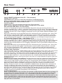
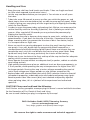
Front Panel
Input
Clean Gain
Lead Gain
Bass
Middle
Treble
Lead Volume
Master A
Master B
Presence
1
2
3
4 5
6
7
8
Clean
Lead
9 1011 12
V2
V3
V4
Power Tube Failure
Indication System
13
14
Fireball 100
Power Tube Monitor
V1
Mid
Boost
Bright Bottom
15a-d
Tube
Amp
Stand By
Power
16
17
1 Input
¼" unbalanced input jack. Plug your guitar in here using a shielded cord.
A tip from the designer:
Depending on the type of cord and its shielding, you may occasionally encounter interference from
sources such as radio stations or powerful magnetic fields. When this occurs, try connecting your guitar
to the amp using different cords. What's more, to minimize signal degradation due to high-frequency
loss, use the shortest cords feasible (as a rule, the shorter the cord, the less susceptible it is to
high-frequency attenuation).
2 Clean Gain
This knob determines input sensitivity of the Clean Channel, in other words, the input level
of the preamp during Clean mode.
A tip from the designer:
The amount of distortion depends on the type of pickups your guitar is equipped with. Single coil
pickups may overdrive the preamp when the knob is set to about the two o'clock position in Clean
operating mode, pickups with very high output levels (humbuckers or active pickups) will evoke
distortion at even lower settings. If you want squeaky clean tone, simply back off the Gain knob
accordingly.
3 Lead Gain
Gain control for the Lead Channel. This Control knob determines input sensitivity when the Lead
channel is active. Use it to dial in the desired amount of preamp saturation level.
CAUTION: Extremely high gain and volume levels in Channlel 2 mode can produce powerful feedback.
Avoid feedback squeals; they can lead to hearing loss and damage speakers! At higher volumes, back
off the Gain and Treble levels in order to prevent unchecked feedback!
4 Bright
This feature boosts the upper end of the high frequency range for the Clean channel. Its intensity
decreases as gain settings increase.
A tip from the designer:
For a crisp or glassy tone, activate the Bright boost. It brightens the sound of humbucking or muddy
pickups. Use it to tweak the amp's tone to taste, activating it to boost top-end frequencies for the
Clean channel or deactivating it to dampen high end response .
5 Bottom
Alters the EQ by boosting the low end range; the Bottom feature affects the Clean Channel & the
Lead Channel.
A tip from the designer:
If you want to ladle an extra helping of bottom-end oomph on specific sounds, I recommend that you
activate the Bottom button. At very high Volume settings, it can be an advantage to deactivate this
function for a more focused, crisper tone with precise definition in the lo end frequency range.
6 Bass
Bottom end voicing control of the preamps´s passive EQ.
7 Middle
Mid-range voicing control of the preamps´s passive EQ.
8 Treble
Upper range voicing control of the preamps´s passive EQ.
TIP´s from the Designer:
To help you get acquainted with the amp's fundamental sounds, I recommend that you set all tone
controls to the center or 12 o'clock position.
For high Gain Lead sounds, your best bet is to turn the Treble knob well down to prevent the pickups
and speakers from interacting at hi levels and generating feedback (the recommended setting is
somewhere in the 10 to 2 o'clock range).
Since the Treble and Presence control knobs sweep through different frequency ranges and influence
the signal at different places in the amp's internal signal chain, you can dial in different combinations
of treble and presence settings to come up with many interesting sonic variations.
9 Lead Volume
Volume control for the Lead channel (pre-FX loop, influences the Send level). The red LED above the
channel switching selector (11) indicates Lead operating mode.
Use this knob to dial in the desired balance of levels between the Lead and Clean channels.
10 Mid Boost
This voicing feature operates globally, affecting both channels by boosting specific midrange
frequencies when activated. The LED above the button lights up to indicate Mid Boost is activated. It
may also be switched using a footswitch connected to jack (20). When a footswitch is plugged in, the
front panel Mid Boost button is disabled.
A tip from the designer:
Mid Boost targets and shapes specific midrange bands crucial in voicing a guitar's sound. This
tone-shaping option is remotely controllable via footswitch, so you can adapt the amp's fundamental
sound on the fly, say to better support rhythm guitar work, singing leads, and slashing power chords.
With a handy MIDI switcher such as the ENGL Z-11, you can assign Clean/Lead channel switching,
Master A/B, Mid Boost and the FX Loop off/on function to different MIDI presets and control these
switching and sound-shaping functions remotely in any configuration using a MIDI footboard.
11 Clean / Lead
Channel selector pushbutton for Clean and Lead modes, red LED indicate Lead mode; This function
can also be activated via the respective footswitch connected to jack 21.
Once a footpedal is connected, the channel selector pushbutton is deactivated.
12 Master A
Master volume A for power amp output (located post FX loop). The red LED next to the knob lights
up when this knob determines the master volume level. Master A/B switching can be accessed via a
footswitch connected to jack 21 (e.g. ENGL Z-4).
13 Master B
Master volume B for power amp output (located post FX loop). The green LED next to the knob lights
up when this knob determines the master volume level. Master A/B switching can be accessed via a
footswitch connected to jack 21 (e.g. ENGL Z-4).
Tip from the Designer:
You can dial in different levels for Master A and Master B, assign these settings to any channel, and
access them directly via the two channel switches on the Z-4 foot controller. This gives you a range of
alternatives that you can apply to different playing styles and musical genres to great dramatic effect.
What's more, you can use the Clean channel for rhythm or cleaner lead lines and the Lead channel's
overdriven preamp stage for power chords and soloing, and go from soft to loud at the touch of a
button. Beyond that, you can also broaden the volume and tonal ranges by working your guitars'
volume knob. If your arsenal includes MIDI gear - for instance, the Z-11 ENGL MIDI Switcher in
combination with a MIDI Footswitch (e.g ENGL Z-9, Z-12, Z-15) - you may use the amp's Master A/B
circuit to swiftly and conveniently set the power amp's volume to two different levels, and then access
these volume presets in combination with preamp voicing features such as Mid Boost.
14 Presence
This control shapes the hi frequency response in the power amp stage and affects both channels.
15a Power Tube Monitor V1
This LED lights up when the current flowing through the V1 power amp tube is too high and the
power tube monitor system has switched that tube off.
See the tube layout chart to locate V1's position on the amp chassis.
15b Power Tube Monitor V2
This LED lights up when the current flowing through the V2 power amp tube is too high and the
power tube monitor system has switched that tube off.
See the tube layout chart to locate V2's position on the amp chassis.
15c Power Tube Monitor V3
This LED lights up when the current flowing through the V3 power amp tube is too high and the
power tube monitor system has switched that tube off.
See the tube layout chart to locate V3's position on the amp chassis.
15d Power Tube Monitor V4
This LED lights up when the current flowing through the V4 power amp tube is too high and the
power tube monitor system has switched that tube off.
See the tube layout chart to locate V4's position on the amp chassis.
An important note on the Power Tube Monitor (P.T.M.) system:
The electronic power amp monitoring system constantly gauges the current flowing through each
power amp tube. If it rises to too high a level the system shuts down the given tube.
This can occur when the amp is operated incorrectly (for example, if the impedance is wrong due to an
incorrect speaker load; refer to #26, #27 and #28 for permissible loads), at extreme power spikes, or
when a tube is defective.
Reset this electronic monitoring system by switching the standby switch off and on again. When you
press the standby switch to turn the amp on again, the system again measures the current sent to the
tube. If it is still too high, the power amp must be checked by a service technician, and the tube may
have to be replaced if it is defective.
IMPORTANT, PLEASE NOTE: do not flip the Stand By switch off and on in short time intervals if a
P.T.M. LED indicates a tube failure. Let a few minutes pass by before you engage the poweramp again
after you have switched it off.
16 Stand By
Power amp standby switch: Use this switch to silence (0 position) the amp when you take a lengthier
break. The amp's tubes stay warm, which means that it is ready to roll immediately when you switch it
back to full power. To reset the power tube monitoring circuitry, press the standby switch briefly (see
Power Tube Monitor).
A tip from the designer:
I suggest you get into the habit of using standby during short breaks. In this mode, current is not piped
through the power tubes, so they don't get as hot (due to the lack of anode dissipation) and are
spared considerable wear. The amp is ready to run when you flip the Standby switch because the
tubes are already warm and don't require time to heat up. For breaks of 30 minutes and longer, I
recommend that you switch the amp off in order to conserve energy.
17 Power
AC power on/off.
Please note: ensure that the Stand By switch (17) is set to Stand By (0 position) before you switch the
amp on. Let the tubes heat up for about 30 seconds before you activate the power amp. This
procedure spares the tubes.
CAUTION: After an extended period of operation and higher ambient temperatures the amps's chassis
can become very hot, therefore avoid touching the rear panel surface !
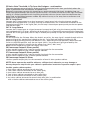
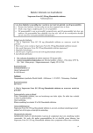
Rear Panel
REPLACE FUSE
ONLY WITH SAME TYPE
AND RATING !
CAUTION !
Footswitch
Noise Gate
Lead Channel
!
R
DO NOT OPEN !
RISK OF ELECTRIC SHOCK !
DO NOT EXPOSE THIS EQUIPMENT
TO RAIN OR MOISTURE !
FX Loop
Tube
Poweramp Output
Amp
100 W All-tube Guitar Amp Head
Fireball 100
TYPE E635
designed by Horst Langer
MADE IN GERMANY
Mid Boost
FX Loop off/on
18 19
Clean/Lead
Master A/B
20 21
4
Off-Lo
Hi
Threshold
22
Or 8
And 8
Or->
8
Or 16
And 16
Or->
16
Dry Effect
Return
Balance
4 Ohms Parallel
8 Ohms Parallel
1 x 4 Ohms
2 x 8 Ohms
1 x 8 Ohms
2 x 16 Ohms
23 24
25
26
Send
27
16 Ohms
28
18 AC SOCKET: (AC Power Inlet; IEC - C14 connector)
Connect an AC cord here.
CAUTION: Ensure you use an intact AC cord with an insulated plug only!
Before you power the amp up, ensure the voltage value printed beside the
AC socket corresponds to the available current.
19 AC Fuse Box
Contains mains fuse (rear chamber) and spare fuse (front chamber).
NOTE: Ensure replacement fuses bear identical ratings (refer to the table)!
20 Footswitch Mid Boost; FX Loop off/on;
Use this 1/4" Stereo jack to connect a conventional footswitch with two switching functions, for
example, the ENGL Z-4 (2 x off/on - Single Pole Single Throw or SPST for short). This type of footswitch
lets you access Mid Boost and FX Loop off/on. One of the two switches activates Mid Boost, while the
the other activates the FX Loop. Plugging a footswitch into this jack disables onboard Mid Boost (10)
switching.
Note also: A footswitch may be equipped with LEDs indicating the given switching status. Each of the
two switches is provided with approx. 10 milliamperes current, which suffices to power a standard
LED. The jack's mono terminal ("tip") selects Mid Boost (passive <--> active), while the stereo terminal
("ring") controls the FX Loop (off <--> on). For pin assignments, see "Wiring of Principal Connectors".
21 Footswitch Channel Clean - Lead; Master A - B;
Use this 1/4" Stereo jack to connect a conventional footswitch with two switching functions, for
example, the ENGL Z-4 (2 x off/on - Single Pole Single Throw or SPST for short). This type of footswitch
lets you access the two channels and Master A/B. One of the two switches activates Clean or Lead,
while the other activates Master A or B. Plugging a footswitch into this jack disables onboard channel
(11) switching.
Note also: A footswitch may be equipped with LEDs indicating the given switching status. Each of the
two switches is provided with approx. 10 milliamperes current, which suffices to power a standard
LED. The jack's mono terminal ("tip") selects Clean <--> Lead switching, while the stereo terminal
("ring") controls the Master A <--> B feature. For pin assignments, see "Wiring of Principal Connectors".
22 Noise Gate Threshold
This control knob activates an onboard Noise Gate serving to suppress excess noise in the Lead channel
when you twist it to the right, near or just beyond the 9 o'clock position. Use this knob to set a
threshold value (that is, the noise level) at which the Noise Gate activates to suppress the signal within
the 9 to 5 o'clock range. The further you twist the knob to the right, the higher the signal level at
which the Noise Gate kicks in. If you set the knob to the 5 o'clock position, the Noise Gate reacts to
extremely high noise levels, meaning that there's not much of a margin between the guitar signal and
background noise.
IMPORTANT note; please read and heed: The Noise Gate may open up inadvertently when the Noise
Gate is activated, a high-gain Lead channel is selected, and the volume exceeds the Threshold knob
setting. At very high volume and gain settings, this may generate instant feedback, particularly if your
guitar is facing the speakers. Rather than musical and controlled, this is the shrill, unpleasant and
potentially harmful variety of feedback squealing that sends your audience and fellow musicians
packing. Though the amp is not more susceptible to feedback when the Noise Gate is activated, the
fact that it suppresses extraneous noise means you can't hear those telltale signs that feedback is
swelling and consequently can't take measures to suppress it. For this reason, make an extra effort to
be careful when the Noise Gate is activated: Before you approach the amp and speaker cabinet with
your guitar in hand, turn the guitar's volume knob to the far left position (to 0 so that no signal is
audible) to prevent the pickups and speakers from interacting!
A tip from the designer:
Noise is a definite no-no in many situations. For example, studio etiquette demands that you keep a lid
on extraneous noise during short breaks. It's in the nature of high gain rigs to generate undesirable
peripheral noise in overdriven channels. This is attributable to the physical properties of an amp's
constituent components, in particular its active components. That's right; those cherished tubes are the
culprits. The Noise Gate is a tool that lets you silence this noise during breaks by way of signal mute
circuit. Note that electric guitars pick up interference signals, and these are amplified tremendously at
high gain levels in Lead mode.
22 Noise Gate Threshold: A Tip from the Designer - continuation
The most common source of noise is 50 Hz or 60 Hz (hertz/cycle) mains hum, particularly when the
guitar is positioned near transformers and power units.
Because in worst-case scenarios this humming can attain extremely high levels, the Noise Gate can
hardly distinguish between the musical signal and noise. This makes it hard to find the right Threshold
setting. It is entirely possible for this humming and other noise to rise to a level that deactivates the
Noise Gate and therefore becomes audible. My advice is to stay as far away from transformers and
power units as space allows.
23 F.X. Loop Send
Connect the FX Loop output to a signal processor's input/return jack using the shortest possible
shielded cord equipped with 1/4" plugs. Activate and deactivate it via a Footswitch connected to the
Footswitch terminal 20. In the signal path, the FX Loop is located post preamp and pre the two power
amp Master knobs.
24 F.X. Loop Return
Connect the FX Loop input to a signal processor's output/send jack using the shortest possible shielded
cord equipped with 1/4" plugs. Activate and deactivate it via a Footswitch connected to the Footswitch
terminal 20. In the signal path, the FX Loop is located post preamp and pre the two power amp Master
knobs.
25 Balance
FX mix control for the FX Loop. When the knob is set to Dry, the amp signal is routed through with no
processed signal (0% wet balance) added to the mix. Twist the knob clockwise to blend in the
processed signal (parallel/passive, wet balance 1-99%, depending on knob position). When the knob
arrives at the Effect position, only the wet signal (that is, the processed signal generated by the
connected effect device) is patched to the power amp (serial, 100% wet).
NOTE: Set this knob to Dry when this loop is not in use!
26 Poweramp Output 4 Ohms parallel
4 ohms speaker output jacks, internal parallel signal path for the connection
of one 4 ohms cabinet or two 8 ohms speaker cabinets.
27 Poweramp Output 8 Ohms parallel
8 ohms speaker output jacks, internal parallel signal path for the connection
of one 8 ohms cabinet or two 16 ohms speaker cabinets.
28 Poweramp Output 16 Ohms
16 ohms speaker output jack, for the connection of one 16 ohms speaker cabinet.
NOTE: Never operate the amplifier without a sufficient load, otherwise you may damage or
destroy the power amp! Ensure your cabinet’s specifications match the respective output’s specs.
Possible speaker cabinet options:
1. One 4-ohm cabinet connected to a 4-ohm jack;
2. Two 8-ohm cabinets connected to the 4-ohm jacks;
3. One 8-ohm cabinet connected to an 8-ohm jack;
4. Two 16-ohm cabinets connected to the 8-ohm jacks;
5. One 16-ohm cabinet connected to the 16-ohm jack;
6. An 8-ohm cabinet connected to one of the 4-ohm jacks in combination
with a 16-ohm cabinet connected to one of the 8-ohm jacks;
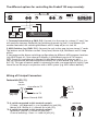
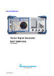
The different options for controlling the Fireball 100 amp remotely:
REPLACE FUSE
ONLY WITH SAME TYPE
AND RATING !
!
CAUTION !
Footswitch
Noise Gate
Lead Channel
R
DO NOT OPEN !
RISK OF ELECTRIC SHOCK !
DO NOT EXPOSE THIS EQUIPMENT
TO RAIN OR MOISTURE !
FX Loop
Tube
Poweramp Output
Amp
100 W All-tube Guitar Amp Head
Fireball 100
TYPE E635
designed by Horst Langer
MADE IN GERMANY
Mid Boost
FX Loop off/on
1.
or
ifier
ON/OFF
Hi
Or 8
And 8
Or->
8
Or 16
And 16
Or->
MIDI
CHANNEL
SWITCH
LOOP 1
SWITCH
LOOP 2
Return
Balance
4 Ohms Parallel
8 Ohms Parallel
1 x 4 Ohms
2 x 8 Ohms
1 x 8 Ohms
2 x 16 Ohms
SWITCH
LOOP 3
SWITCH
LOOP 4
SWITCH
LOOP 5
SWITCH
LOOP 6
ON/OFF
1. Two-way footswitch (e.g. ENGL Z-4): Connect it to the amp via a stereo ¼" cord. You
will need one two-way footswitch for switching channels via Jack 21 and Master A/B
another footswitch for switching Mid Boost and FX Loop off/on via Jack 20.
2. MIDI-Switcher (e.g. ENGL Z-11): Connect the unit to the amp via two stereo ¼" cords.
The buttons on the Switcher controls Clean/Lead, Master A/B, Mid Boost and FX Loop
off/on.
If you program the diverse switching configurations to different MIDI program locations
(e.g. MIDI Preset #1: Clean channel & Master A & Mid Boost passive & FX Loop on;
MIDI Preset #2: Lead channel & Master B & Mid Boost acive & FX Loop on, etc.)
you can activate the desired configuration directly via a MIDI board (e.g. ENGL Z-9, Z-12
or Z-15). This type of control option is extremely versatile, we recommend it highly if you
intend to use the amp in conjunction with a MIDI system (e.g. MIDI effects devices).
Wiring of Principal Connectors
Footswitch (20, 21)
Stereo
1/4" jack
ring: refer to *2
Use a stereo
plug only!
16
Dry Effect
Send
MIDI SWITCHER
Tube Ampl
WRITE
ON/OFF
Off-Lo
Threshold
2.
ifier
Tube Ampl
ON/OFF
4
Clean/Lead
Master A/B
tip *3
ring *2
sleeve
tip: refer to *3
sleeve: Ground, GND
Stereo
1/4" plug
*2: A switch connected to this terminal controls
FX Loop - off (bypassed) <--> on (enabled) via jack (20);
Master A/B - Master A <--> Master B via jack (21);
*3: A switch connected to this terminal controls
Mid Boost - passive <--> active via jack (20);
Channel switching - Clean <--> Lead via jack (21);
Footswitch
Mid Boost
Clean / Lead
FX Loop off/on Master A/B
20
21
16 Ohms
Technical Data:
Rated power:
Input sensitivity level Input, Clean channel:
Input sensitivity FX RETURN:
Output level FX SEND, level range:
Tubes:
V5:
V6, V7:
V8:
V1 - V4:
Fuses:
external:
internal:
(internal fuse located at the power transformer)
Important:
Power Consumption:
Dimensions:
(W x H x D)
Weight:
approx. 100 watts at 4, 8 or 16 ohms;
-20 dBV nominal, max. 0 dBV
from -20 dBV to -10 dBV nominal, max. 0 dBV
from -20 dBV to -10 dBV nominal, max. 0 dBV
ECC 83 / 12AX7 /7025, FQ selected;
ECC 83 / 12AX7 selected;
ECC 83 / 12AX7, standard;
6L6GC matched sets.
1.6 ATL (slow) for the 230 Volt model;
3.15 ATL (slow) in the 100 and 120 Volt models.
2 ATL (slow) for the 230 Volt model;
4 ATL (slow) in the 100 and 120 Volt models.
Replace fuses only against same type and rating!
300 watts max.
approx. 71 x 27 x 27 cm; 28" x 10.6" x 10.6";
approx. 21 kg; 46.3 lbs;
Tube array:
V1
V2
V3
V4
Output
Transformer
V5
V6
V7
V8
Power
Transformer
the tubes and their function:
V 5 - ECC83 (12AX7 or 7025): input stage, 2. stage; grade: FQ selected
V 6 - ECC83 (12AX7): Lead driver stage, 4. stage; grade: selected
V 7 - ECC83 (12AX7): FX buffer stage, poweramp driver stage; grade: selected
V 8 - ECC83(12AX7): phase splitter; grade: standard
V 1 - V 4: 6L6GC or 5881: power tubes, poweramp, matches sets
Tube replacement report:
1. Replaced on: _ _ _ _ _ _ _ 20 _ _ _ Replaced by: _ _ _ _ _ _ _ _ _ _ _ _ _ _
Replaced tubes: _ _ _ _ _ _ _ _ _ _ _ _ _ _ _ _ _ _ _ _ _ _ _ _ _ _ _ _ _ _ _ _ _ _
Reason: _ _ _ _ _ _ _ _ _ _ _ _ _ _ _ _ _ _ _ _ _ _ _ _ _ _ _ _ _ _ _ _ _ _ _ _ _ _ _ _ _ _
2. Replaced on: _ _ _ _ _ _ _ 20 _ _ _ Replaced by: _ _ _ _ _ _ _ _ _ _ _ _ _ _
Replaced tubes: _ _ _ _ _ _ _ _ _ _ _ _ _ _ _ _ _ _ _ _ _ _ _ _ _ _ _ _ _ _ _ _ _ _
Reason: _ _ _ _ _ _ _ _ _ _ _ _ _ _ _ _ _ _ _ _ _ _ _ _ _ _ _ _ _ _ _ _ _ _ _ _ _ _ _ _ _ _
3. Replaced on: _ _ _ _ _ _ _ 20 _ _ _ Replaced by: _ _ _ _ _ _ _ _ _ _ _ _ _ _
Replaced tubes: _ _ _ _ _ _ _ _ _ _ _ _ _ _ _ _ _ _ _ _ _ _ _ _ _ _ _ _ _ _ _ _ _ _
Reason: _ _ _ _ _ _ _ _ _ _ _ _ _ _ _ _ _ _ _ _ _ _ _ _ _ _ _ _ _ _ _ _ _ _ _ _ _ _ _ _ _ _
Troubleshooting
* The amp does not power-up after you have switched the power on.
The control lamp inside the power switch (17) does not light.
-> Is the mains cord connected to the receptacle / live power source ?
-> Is the power cable you are using intact ? Try another equal mains cable.
-> Is the mains lead properly connected to the AC Power Inlet (18) at the amp ?
-> Possibly the mains fuse (19) has blown, unplug the mains cord from the mains connector
and the receptacle and check the mains fuse.
* The amp does not power-up after you have switched the power on. The control lamp inside the
power switch (17) lights up but the Channel & Mid Boost switching functions do not react,
i.e. the corresponding control LED's do not indicate an active function;
moreover no sound is emanating from the connected speaker.
-> Possibly the internal mains fuse has blown. Let this fuse check by a professional technician.
* The amp fails to respond when you try to control switching functions remotely
using a footboard such as the Z-4 or a MIDI switcher such as the ENGL Z-11.
-> Are the footboards or switching loops connected to the corresponding footswitch jacks (20, 21) ?
-> Are the cords you are using stereo, intact, and wired properly ?
(Refer to "Wiring of Principal Connectors" for pin assignments.)
-> If you are using footswitches other than an ENGL Z-4 or Z-11, are the switches or relays inside the
boards or switching loop systems off / on Single Pole Single Throw (SPST) switches? In other words,
do these switches continuously connect to GND when you wish to activate the given function?
If you're unsure about the answers to these questions, consult an authorized service center or a
professional specialist.
* The amp is not providing an output signal / no sound is emanating from the speaker.
-> Is at least one speaker connected to the speaker outputs 4 ohms, 8 ohms or 16 ohms (26, 27, 28) ?
-> Is the power amp activated (Standby switch to ON) ?
-> Are all cords (guitar, effect, and speaker) connected properly and are they functional ?
-> Unplug connected effectors and see if the preamp works fine without these peripheral devices.
-> Is the Noise Gate activated in the Lead channel and the Threshold (22) knob set to a high value?
Deactivate the Noise Gate (22) for a quick check.
-> Are the active Master knob and the Gain and Volume knobs set to a value greater than 0 ?
If any of these knobs is set to 0, no signal is routed to the amp's outputs.
-> You may be looking at a faulty tube or another defect. In this case,
be sure to take the preamp to an authorized, professional service center.
* The speaker is emitting humming noises:
-> Is there a connection (for example, via a shielded circuit) between the amp and another device
that is grounded via a power plug of its own?
Two or more circuits sharing a common electrical ground line can cause audible hum.
If low-frequency noise is emanating from your rig, be sure to consult a specialist.
-> The amp and mains grounds are not connected properly or are altogether disconnected.
Have an experienced specialist check this.
-> Cords connected to the input or effect loops may not be shielded properly.
Replace them to check if this is indeed the case.
-> The amp or speaker cords may be picking up interference from powerful magnetic fields
(for example, of nearby power transformers or electrical motors).
Reposition the amp and connector cables.
-> The amp or speaker cords may be picking up radio signals, for example, from activated mobile
telephones or powerful local transmitting stations nearby.
Switch off mobile phones while troubleshooting noise problems.
* The electronic power amp protection circuit has tripped:
-> The given power tube is defective and must be replaced if the electronic circuit breaker continues
to trip after several attempts to reset the Tube Monitoring System by flipping the Standby switch
off and back on again.
IMPORTANT, PLEASE NOTE: do not flip the Stand By switch off and on in short time intervals
if a P.T.M. LED (15a-d) indicates a tube failure. Let a few minutes pass by before you engage
the poweramp again after you have switched it off.
-> The amp has been overloaded, perhaps by excessive volume levels, mains over-voltage,
or the wrong output impedance (the impedance setting does not match the connected
speaker's impedance).
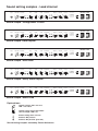
Sound setting samples - Clean channel
Input
Clean Gain
Lead Gain
Bass
Middle
Treble
Lead Volume
Master A
Master B
Presence
Mid
Boost
Clean
Lead
Fireball 100
Power Tube Monitor
V1
Bright Bottom
V2
V3
V4
Power Tube Failure
Indication System
Tube
Amp
Stand By
Power
Sound sample 1: Crystal Clean
Input
Clean Gain
Lead Gain
Bass
Middle
Treble
Lead Volume
Master A
Master B
Presence
V1
Mid
Boost
Bright Bottom
Clean
Lead
Fireball 100
Power Tube Monitor
V2
V3
V4
Power Tube Failure
Indication System
Tube
Amp
Stand By
Power
Sound sample : Jazzy Whispers Clean
Input
Clean Gain
Bass
Lead Gain
Middle
Treble
Master A
Lead Volume
Master B
Presence
V1
Mid
Boost
Bright Bottom
Clean
Lead
Fireball 100
Power Tube Monitor
V2
V3
V4
Power Tube Failure
Indication System
Tube
Amp
Stand By
Power
Sound sample : LA Hairy Clean
Input
Clean Gain
Lead Gain
Bass
Middle
Treble
Lead Volume
Master A
Master B
Presence
Mid
Boost
Clean
Lead
Fireball 100
Power Tube Monitor
V1
Bright Bottom
V2
V3
V4
Power Tube Failure
Indication System
Tube
Amp
Stand By
Power
Sound sample : Blues Crunch
Input
Clean Gain
Bass
Lead Gain
Middle
Treble
Master A
Lead Volume
Master B
Presence
Mid
Boost
Clean
Lead
Fireball 100
Power Tube Monitor
V1
Bright Bottom
V2
V3
V4
Power Tube Failure
Indication System
Tube
Amp
Stand By
your own setting:
Explanations:
control settings does not care,
LED´s are not lit.
control setting for the described
sound sample; LED is lit.
button setting does not care.
button in Off position.
button in On position (pressed).
Sound setting samples created by: Bernd Aufermann
Power
Sound setting samples - Lead channel
Input
Clean Gain
Bass
Lead Gain
Middle
Treble
Master A
Lead Volume
Master B
Presence
Clean
Lead
Fireball 100
Power Tube Monitor
V1
Mid
Boost
Bright Bottom
V2
V3
V4
Power Tube Failure
Indication System
Tube
Amp
Stand By
Power
Sound sample : Vintage Blues Crunch
Input
Clean Gain
Lead Gain
Bass
Middle
Treble
Lead Volume
Master A
Master B
Presence
V1
Bright Bottom
Mid
Boost
Clean
Lead
Fireball 100
Power Tube Monitor
V2
V3
V4
Power Tube Failure
Indication System
Tube
Amp
Stand By
Power
Sound sample: Rock Rhythm
Input
Clean Gain
Lead Gain
Bass
Middle
Treble
Lead Volume
Master A
Master B
Presence
V1
Bright Bottom
Mid
Boost
Clean
Lead
Fireball 100
Power Tube Monitor
V2
V3
V4
Power Tube Failure
Indication System
Tube
Amp
Stand By
Power
Sound sample : Rock Lead
Input
Clean Gain
Lead Gain
Bass
Middle
Treble
Lead Volume
Master A
Master B
Presence
Mid
Boost
Clean
Lead
Fireball 100
Power Tube Monitor
V1
Bright Bottom
V2
V3
V4
Power Tube Failure
Indication System
Tube
Amp
Stand By
Power
Sound sample : Heavy Metal Rhythm
Input
Clean Gain
Bass
Lead Gain
Middle
Treble
Master A
Lead Volume
Master B
Presence
V1
Bright Bottom
Mid
Boost
Clean
Lead
Fireball 100
Power Tube Monitor
V2
V3
V4
Power Tube Failure
Indication System
Tube
Amp
Stand By
Sound sample : Metal Lead
Explanations:
control settings does not care,
LED´s are not lit.
control setting for the described
sound sample; LED is lit.
button setting does not care.
button in Off position.
button in On position (pressed).
Sound setting samples created by: Bernd Aufermann
Power
Handling and Care
* Keep the amp safe from hard knocks and shocks. Tubes are fragile and tend
to suffer when exposed to mechanical stress!
* Let the amp cool down before you transport it. Ten minutes or so will spare
the tubes.
* Tubes take some 20 seconds to warm up after you switch the power on, and
about two to three minutes before they are able to pump out full power. Make
a habit of giving your amp plenty of time to get toasty and flipping the Standby
switch for short breaks.
* In order to spare the power tubes and prolong their lifetime, we recommend to
set the Stand By switch to Stand By (0 position, that is) before you switch the
amp on. After a period of 30 seconds you may activate the poweramp by
flipping the Stand By switch.
* Avoid storing the amp in damp or dusty rooms to spare jacks, switches and
potentiometers. If you don't use the amp all the time, I recommend that you
drape a covering over it to prevent the intrusion of dust. Even better, keep it
in a transport cover or flight case.
* Never use caustic or scouring detergents to clean the amp's housing, front or
rear panels. Use a soft, damp cloth or sponge with diluted soapsuds or a
standard brand of mild dishwashing liquid instead. Never use solvents they can
corrode the amp's vinyl skin and dissolve the front and rear panel labels. Keep
liquids well away from the amp, particularly the interior of the housing.
* Make sure air can circulate at the front and top of the amp to allow for adequate
cooling, which increases component life.
* Never operate the amp without an adequate load (a speaker, cabinet or suitable
terminating resistor).
* High ambient temperatures place an additional strain on diverse components; so
if at all possible, avoid operating the amp at temperatures far higher than 30°C
for longer periods. Running the amp at mains voltages exceeding the nominal
mains input voltage over longer periods can also shorten component life.
* Replace tubes with selected tubes that satisfy ENGL selection criteria to forestall
microphonic properties, undesirable noise and unbalanced power amp signals.
Because power tubes' idle current (bias) must checked and possibly adjusted
when replacing tubes, this is a job best left to experienced and authorized
specialists.
CAUTION! Please read and heed the following:
You'll find an ancillary pamphlet accompanying this owner's manual entitled Instructions
for the Prevention of Fire, Electrical Shock and Injury.
Be sure to read it before you plug in and power up the amp!
ENGL Gerätebau GmbH, 84529 Tittmoning, Germany
Internet: www.engl-amps.com
Text, design, graphics and layout by Horst Langer
We reserve the right to make unannounced technical upgrades!