1
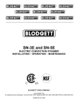
SC-7E and SC-10E
ELECTRIC CONVECTION STEAMER
INSTALLATION – OPERATION – MAINTENANCE
BLODGETT OVEN COMPANY
www.blodgett.com
44 Lakeside Avenue, Burlington, Vermont 05401 USA Telephone: (802) 658-6600 Fax: (802) 864-0183
1 B (7/10)
S00058 Rev
IMPORTANT NOTES FOR INSTALLATION AND OPERATION
This is the safety alert symbol. It is used to alert you to potential personal
injury hazards. Obey all safety messages that follow this symbol to avoid
possible injury or death.
WARNING: Improper installation, operation, adjustment, alteration,
service or maintenance can cause property damage, injury or death. Read
the installation, operating and maintenance instructions thoroughly before
installing, operating or servicing this equipment.
Adequate clearances must be maintained for servicing and proper operation.
Intended for commercial use only. Not for household use.
This manual should be retained for future reference.
2
TABLE OF CONTENTS
DESCRIPTION
PAGE
1.0 Service Connections ............................................................................................. 4
2.0 Installation Instructions ........................................................................................... 5
3.0 Operation ............................................................................................................. 9
4.0 Cleaning .............................................................................................................. 13
5.0 Maintenance ...................................................................................................... 15
6.0 Troubleshooting.................................................................................................... 16
7.0 Service ................................................................................................................ 17
3
1.0 SERVICE CONNECTIONS
ELECTRICAL CONNECTION: 1-1/8" hole for electrical connection. Rating to be as specified on data plate.
DRAIN: 1"IPS to open floor drain. No solid connection. Use copper only, 24" length before open air gap opening (No bends or elbows).
GENERATOR WATER: 3/8" O.D. tubing at 25-50 PSI (170-345 kPa)
C
CONDENSING WATER: 3/8" O.D. tubing at 25-50 PSI (170-345 kPa)
WATER QUALITY STATEMENT
WATER QUALITY IS THE MAJOR FACTOR AFFECTING THE PERFORMANCE OF YOUR APPLIANCE. IF YOU ARE UNSURE OF WATER
QUALITY, CONSULT A LOCAL WATER TREATMENT SPECIALIST AND HAVE THE WATER ANALYZED. YOUR WATER SUPPLY MUST BE
WITHIN THESE GENERAL GUIDE LINES:
TOTAL DISSOLVED SOLIDS
LESS THAN 60 PPM
TOTAL ALKALINITY
LESS THAN 20 PPM
SILICA
LESS THAN 13 PPM
CHLORIDE
LESS THAN 1.5 PPM
pH FACTOR
7.0-8.5
WATER WHICH FAILS TO MEET THESE STANDARDS SHOULD BE TREATED BY INSTALLATION OF A WATER CONDITIONER.
FAILURE OR MALFUNCTION OF THIS APPLIANCE DUE TO POOR WATER QUALITY IS NOT COVERED UNDER WARRANTY.
ELECTRICAL CHARACTERISTICS
MODEL
kW
SC-7E
17.5
SC-10E
PHASE
220V
3
48.6
45.9
24 - Std
3
66.6
63
30 - Opt
3
83.3
78.7
AMPS PER LINE
240V
380V
480V
26.6
21.1
57.8
36.5
28.9
72.2
45.6
36.1
42.1
REAR FLANGED FOOT DETAIL
2 EQUALLY SPACED
Ø7/16" [11mm] HOLES
ON 2.5 [63] B.C.
24 [610]
1.75 [45]
SC-7E
3 [76]
16.75 [425]
2.19 [56]
19.5 [495]
2.19 [56]
4
33 [838]
1.38 [35]
2.19 [56]
3.94 [100]
27.69 [703]
27.38 [695]
88.5 [1740] SC-10E
58.75 [1492] SC-7E
1.5 [38]
5 [127]
28 [711]
6 [152]
1 [25]
16.62 [422]
19.88 [505]
1/2-NPT DELIME INLET
9 [229]
1.12 [29]
SC-10E
2.62 [67]
208V
2.0 INSTALLATION INSTRUCTIONS
This steamer was inspected before leaving the factory. The transportation company
assumes full responsibility for safe delivery upon acceptance of the shipment.
Immediately after unpacking the steamer, check for possible damage. If the steamer is
found to be damaged after unpacking, save the packaging material and contact the
carrier within 15 days of delivery.
Prior to installation, verify that the electrical service agrees with the specifications on the
machine data plate which is located on the left side panel.
LOCATION
Allow space for plumbing and electrical connections. Minimum clearances are 3" (76
mm) on the sides and 6" (152 mm) on the back for proper air circulation. Allow adequate
access for operating and servicing the steamer, 36" (915 mm) at the front of the steamer
and 15" (381 mm) above the steamer.
LEVELING AND ANCHORING
1. Using a spirit level or pan of water in the bottom of the steamer, adjust the leveling
feet to level the steamer front-to-back and side-to-side.
2. Mark hole locations on the floor through the anchoring holes provided in the flanged
adjustable feet. Remove the steamer and drill holes at marked locations on the floor.
Insert proper anchoring devices.
3. Set steamer back in proper position.
4. Install bolts through anchoring holes and into anchors to secure the steamer to the
floor. Seal bolts and flanged feet with Silastic.
5. After the drain is connected, check for level by pouring water onto the floor of the
compartment. All water should drain through the opening at the back of the
compartment cavity.
5
ELECTRICAL CONNECTION
WARNING: Electrical grounding connections must comply with
applicable portions of the National Electrical code and/or other local
electric codes.
WARNING: Disconnect the power supply to the appliance before
cleaning or servicing.
Make electrical connection through the 1-1/8" (29 mm) diameter hole provided using 3/4"
(19mm) trade size conduit. Refer to the wiring diagram located inside the right side
panel. Use 90°C minimum insulated wire.
PLUMBING CONNECTIONS
WARNING: Plumbing connections must comply with applicable
sanitary, safety, and plumbing codes.
The water supply inlets are provided with 3/8" (10 mm) compression fittings for 3/8" O.D.
copper tubing. The water supply line pressure should be 25 - 50 psi (170 - 345 kPa) for
each line. The water supply to the generator tank is separate from the water supply to
the cooling system where steam is condensed before entering the drain line.
Install line strainers (not provided). A manual shutoff valve for each supply line must be
provided convenient to the steamer.
We recommend treated water feeding the boiler inlet supply, and untreated water
feeding the cooling system inlet. Hook-ups are labeled on the back of the steamer.
6
DRAIN CONNECTIONS
The drain connection must be 1" (25 mm)
IPS down, preferably with one or two
elbows only, maximum length 6 feet (1830
mm) and piped to an open gap type drain
(Figure 1). Drain pipe should be either iron
or copper. DO NOT use PVC pipe – PVC
pipe may lose its rigidity or glue may fail.
CAUTION: To avoid
injury or damage to the
steamer, do not connect
solidly to any drain
connection.
WATER QUALITY
The water supply connected to the steam generator should meet the following
guidelines:
Failure to comply with water quality statement on page 4 may void the warranty.
Water supplies vary from one location to another. Other factors affecting steam
generation are iron content, chlorides, and dissolved gasses. A local water treatment
specialist should be consulted before installing any steam generating equipment.
Untreated water contains scale producing minerals which can precipitate onto the
surfaces in the boiler. Due to the temperatures in the boiler, the minerals can bake onto
the surfaces and components. This can result in early component failure and reduced
product life.
Mineral scale on components causes several problems:
1. The surfaces of the heating devices become coated with scale, reducing the heat
transfer efficiency. This can produce hot spots on the heating elements and result in
premature failure.
2. The water level probes become coated with scale. Scale will bridge across the probe
insulator from the metal extension which senses the water level in the boiler shell.
Once this scale becomes wet, the water level control is unable to maintain the proper
water level in the boiler. This situation may cause an electric heating element to fail if
the element is not adequately covered by water.
Strainers and filters will not remove minerals from the water.
Refer to REMOVAL OF LIME SCALE DEPOSITS section in this manual.
7
VENT HOOD
Some local codes may require the steamer to be located under an exhaust hood.
Information on the construction and installation of ventilating hoods may be obtained
from NFPA Standard No. 96, Vapor Removal from Cooking Equipment, (latest edition).
START-UP TEST
WARNING: The steamer and its parts are hot. Use care when
operating, cleaning or servicing the steamer. The cooking
compartment contains live steam. Stay clear while opening the door.
Once the steamer is installed and all mechanical connections have been made,
thoroughly test the steamer before operation.
1. Check that proper water, drain, and electrical connections have been made.
2. Turn main power switch ON. After approximately 15 minutes, the READY light
should come on, indicating that the water temperature is 205°F (96°C).
3. When the READY light comes on, set the timer at 5 minutes. With door open,
observe that no steam is entering the compartment and the COOKING light is OFF.
4. Close compartment door. The COOKING light should now be lit and steam should be
heard entering the compartment after about 45 seconds (5 minutes if boiler is
empty).
5. Check drain line to ensure that water from the cold water condenser is flowing
through the drain line.
6. Open compartment door and observe that steam supply to the chamber is cut off
(READY light should again come on and COOKING light goes off).
7. Close compartment door and let cooking cycle finish. When the timer returns to the
“O” position, a buzzer will sound, signaling the end of the cooking cycle. To silence
the buzzer, turn the dial timer to OFF.
8. Complete the above steps for each cooking compartment.
9. To shut the steamer down, turn the main power switch OFF and leave the
compartment doors slightly open to allow the inside to dry out.
8
3.0 OPERATION
WARNING: Live steam and accumulated hot water in the
compartment may be released when the door is opened.
WARNING: An obstructed drain can cause personal injury or
property damage.
CONTROLS
Main Power Switch
ON
-
The boiler will automatically fill and begin heating to the preset
temperature.
OFF
-
The boiler will drain.
DELIME
-
Closes the drain valve while CLR liquid is being poured into the
generator during the delime procedure.
Ready Light
-
Indicates the temperature has reached 205°F and that the
steamer is ready to begin cooking.
Cooking Light
-
Indicates that a cooking cycle is in progress.
Timer
-
Set the cooking time (0 to 60 minutes). Steam cooking will begin
when the door is closed. The cooking cycle will be interrupted if
the door is opened during the cooking cycle; resume cooking by
closing the door.
When done, a buzzer sounds and steam supply to the cooking
chamber will cease. Turn the timer OFF to stop the buzzer.
9
3.0 OPERATION (Continued)
BEFORE FIRST USE
Clean the protective oils from all surfaces of the steamer. Use a non-corrosive, grease
dissolving commercial cleaner, following manufacturer’s directions. Rinse thoroughly and
wipe dry with a soft clean cloth.
PREHEAT
Turn the main power switch ON. When the READY light comes on, set the timer to 1
minute to preheat the compartment. This should be done when the steamer is first used
for the day or whenever the chamber is cold. The door should be closed during the
preheat cycle. The COOKING light will be lit. When the buzzer sounds, set the timer to
the OFF position. The steamer is now ready to cook.
COOK
With compartment preheated and READY light ON, place pans of food into the
compartment and close the door. Set timer to desired cooking time. (The cooking cycle
may be interrupted at any time by opening the door. To resume operation, close the
door.) Steam will flow into the compartment and the COOKING light will be lit.
At the end of the cooking cycle, the buzzer will sound, the COOKING light will go off and
steam supply to the compartment will cease. Turn the timer to the OFF position to
silence the buzzer.
SHUTDOWN
Turn main power switch OFF. The boiler will automatically blow down. Leave the
compartment door open to allow the inside to dry out. For an extended shutdown, turn
the main power switch OFF; turn power and water supply OFF.
10
CONSTANT STEAM FEATURE, (OPTIONAL)
A switch has been added to control this feature. It is located below the timer under the
heading “COOKING MODE”.
TIMED COOKING
The switch must be positioned to the right, towards the heading “TIMED COOKING”.
The steamer will then operate as described in the previous section. At the end of the
cook time an audible buzzer will sound.
CONSTANT STEAM COOKING
The switch must be positioned to the left towards the heading “CONTINUOUS
COOKING”. This mode will give continuous steam to the cooking chamber until the
operator either turns the selector switch to the “TIMED COOKED” position, or turns
power OFF to the steamer. When cooking is complete, or not in use, the constant steam
cooking feature should be shut off. This prevents the boiler from running unnecessarily.
This will help conserve water, and will reduce boiler maintenance.
SHUT DOWN
Turn the selector switch to TIMED COOKING. Turn main power switch to the “OFF”
position.
DRAINING THE BOILER
Drain the boiler after each day’s use to flush out minerals and minimize scale build-up.
The boiler drains automatically for approximately 4 - 6 minutes after the main power
switch is turned off.
ADJUSTMENT FOR HIGH ALTITUDE LOCATIONS
The steamer has been factory set so that when it is ON, and during the READY phase, it
will maintain water temperature in the steam generator tank at approximately 205°F
(96°C) (just below water boiling point). However, for high altitude locations, an
authorized service agency must adjust the steamer to achieve this temperature.
11
COOKING HINTS
Your steamer efficiently cooks vegetables or other foods for immediate serving. Steam
cooking should be carefully time controlled. Keep hot food holding-time to a minimum to
produce the most appetizing results. Prepare small batches, cook only enough to start
serving, then cook additional amounts to meet demand.
Preparation
Prepare vegetables, fruits, meats, seafood, and poultry normally by cleaning, separating,
cutting, removing stems, etc. Cook root vegetables in a perforated pan. Other
vegetables may be cooked in a perforated pan unless juices are being saved. Liquids
can be collected in a solid pan placed under a perforated pan.
Perforated pans are used for frankfurters, wieners, and similar items when juices do not
need to be preserved. Solid pans are good for cooking puddings, rice and hot breakfast
cereals. Vegetables and fruits are cooked in solid pans in their own juice. Meats and
poultry are cooked in solid pans to preserve their juice or return broth.
Canned foods can be heated in their opened cans (cans placed in solid pans), or the
contents may be poured into solid pans. DO NOT place unopened cans in the steamer.
Frozen Food Items
Separate frozen foods into smaller pieces to allow more efficient cooking.
Use a pan cover for precooked frozen dishes that cannot be cooked in the covered
containers in which they are packed if they require more than 15 minutes of cooking
time. When a cover is used, approximately one-third additional cooking time is
necessary. Cooking time for frozen foods depends on the amount of defrosting required.
If time permits, allow frozen foods to partially thaw overnight in a refrigerator. This will
reduce their cooking time.
12
4.0 CLEANING
WARNING: DO NOT use cleaning agents that are corrosive.
WARNING: Disconnect the power supply to the appliance before
cleaning or servicing.
At the end of each day, or between cooking cycles if necessary...
Turn main power switch OFF.
Remove pans and racks from compartment and wash in sink.
Wash compartment interior with clean water. Never use steel wool or abrasive scouring
pads as they will scratch and ruin the general surface appearance of the steamer.
Use warm soapy water with a cloth or sponge to clean the exposed bead of the door
gasket. Rinse with warm clear water and wipe dry with a dry cloth.
Wipe surfaces which touch the door gasket with a cloth or sponge and warm soapy
water. Rinse with warm clear water and wipe with a dry cloth. CAUTION: Do not allow
the door gasket to come in contact with food oils, petroleum solvents, or
lubricants. Wipe all solids away from the drain openings in the compartments to prevent
clogging.
Remove drain screens from inside compartment drains. Using a plastic bottle brush and
mild detergent, clean inside the drain opening ensuring there is no food residue or
blockage. Clean the drain screen and replace in its original position.
Leave the door slightly open when the steamer is not in use to allow the inside to dry
out.
Weekly, or more often if necessary...
Clean exterior with a damp cloth and polish with a soft dry cloth. Use a non-abrasive
cleaner to remove discolorations.
13
GUIDELINES FOR MAINTAINING STAINLESS STEEL SURFACES
There are three things that can break down stainless steel and allow corrosion to
develop:
1) Abrasion;
2) Deposits and water;
3) Chlorides.
Avoid rubbing with steel pads, wire brushes, or scrapers that can leave iron deposits on
stainless steel; instead, use plastic scouring pads or soft cloths. For stubborn stains, use
products such as Cameo, Talc, or Zud First Impression. Always rub parallel to polish
lines or with the grain.
Hard water can leave deposits that promote rust on stainless steel. Treated water from
softeners or certain filters can eliminate these mineral deposits. Other deposits from food
or lubrication must be properly removed by cleaning. Use mild detergent and nonchloride cleaners. Rinse thoroughly. Wipe dry. If using chloride containing cleaners or
sanitizers, rinse repeatedly to avoid stainless steel corrosion. Where appropriate, apply
a polish recommended for stainless steel (such as Benefit or Super Sheen) for extra
protection and luster.
14
5.0
MAINTENANCE
REMOVAL OF SCALE DEPOSITS
WARNING: Read and follow instructions on the CLR bottle. Use
plastic or rubber gloves to avoid skin contact. IF CLR comes in
contact with skin, rinse and clear water.
1. Drain steam generator tank by setting ON/OFF switch to off. Set cooking timer to
“OFF”.
2. Set switch to de-lime. This closes drain valve.
3. Unscrew plug in deliming port at rear of unit. Insert hose in delime fitting. Pour 28
ounces of solution into generator slowly to avoid spillage. Remove hose. Screw plug
into deliming fitting so it seals tightly.
4. Allow steamer to remain in ready cycle for ½ hour then turn ON/OFF switch off and
allow generator to drain.
5. Flush cycle. Turn ON/OFF switch to on. When ready light comes on, switch to off to
flush generator. Repeat this step three times to completely flush generator.
6. Clean exterior and interior. Use a mild solution of soap and water. Rinse with clean
water. Dry with a soft clean cloth. Leave compartment door open when not in use.
7. The steamer is now ready for use or turn off for overnight shutdown.
15
6.0 TROUBLESHOOTING
PROBLEM
POSSIBLE CAUSES
Cold water flows continuously into drain
when steamer is OFF.
Either or both solenoid valves are not
closing. Contact your authorized service
agency to repair or replace solenoid
valves.
Water overflowing into cooking
compartment.
Problem with operating probe caused by
either:
1. Short between probe terminal and
body of steamer. Contact your
authorized service agency.
2. Excessive scale build-up on probe.
Contact your authorized service
agency. Have water quality analyzed
and corrected immediately to avoid
damage to steamer.
Heater elements do not come on.
1. Problem with contactors or thermostat
coated with scalant. Contact your
authorized service agency. Have water
quality analyzed and corrected
immediately to avoid damage to
steamer.
16
7.0 SERVICE
ADJUSTMENT FOR HIGH ALTITUDE LOCATIONS
NOTICE: Contact the factory, the factory representative or local service
company to perform maintenance and repairs.
The steamer has been factory set so that when it is ON and during the READY phase, it
will maintain water temperature in the steam generator tank at approximately 205
degrees Fahrenheit (just below water boiling point). However, for high altitude locations,
an authorized servicer must adjust the steamer to achieve this temperature. To adjust:
1. Remove side panel and turn control panel power switch to ON.
2. Open compartment door, and after about 15 minutes, steam will be seen, entering
the cooking compartment.
3. Turn thermostat shaft counterclockwise to lower temperature until steam just ceases
to enter cooking compartment and READY light goes on.
4. Replace side panel.
5. Follow TESTING PROCEDURES in this manual.
WATER FLOWS INTO DRAIN DURING SHUTDOWN
When steamer is shut down and cold water is running continuously into the open drain,
either or both solenoid valves did not close when steamer was turned off.
1. Disassemble solenoid valve(s) and examine for scale or foreign particles lodged in
diaphragm or core tube.
2. Clean valve(s) thoroughly and reassemble, or replace valve(s).
17
8.0 SERVICE (Continued)
WATER OVERFLOWS INTO COOKING COMPARTMENT
When steamer is first turned on for the day, and the following conditions occur:
-
READY light does not come on after about 15 minutes,
-
Water begins to overflow into cooking compartment,
-
Water fill solenoid valve is open,
then any or all of these symptoms may indicate a problem with the operating probe due
to either:
1. A short between the operating probe terminal and body of the steamer. Call your
authorized servicer.
2. Excessive scale build-up on the operating probe. This acts as an “insulation” and
prevents the probe from sensing the water level. It is therefore unable to close the
water fill (solenoid) valve to shut off the water.
As a temporary solution, with power OFF, unscrew probes, check visually, and clean
or chip off scalant. Replace probe.
This problem is an indication of severe harmful water conditions which should be
corrected immediately to avoid damage to the components and ultimate malfunction
of the steamer. (See WATER CONDITIONING in this manual).
HEATER ELEMENTS DO NOT COME ON
When the steamer is turned ON and heater elements do not activate, and therefore, the
READY light does not come on, then the contactors may be burned out. If a
considerable amount of “chattering” of contactors has been previously experienced, then
the thermostat bulb may be coated with scalant and unable to sense water temperature
in the boiler accurately, and therefore unable to control the contactors.
1. Replace contactors.
2. Unscrew operating thermostat bulb, clean off scalants and screw thermostat bulb
back in.
This problem is an indication of inadequate water quality and is not covered under the
warranty. Have water quality analyzed and corrected immediately to avoid complete
malfunction of the steamer.
18