1
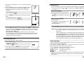
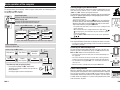
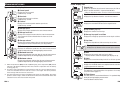
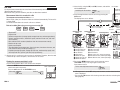
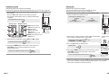
Introduction
Important
• Always follow the sections that are marked with “ Warning!!!”.
• No part of this manual may be reproduced or transmitted without the prior written
permission of CatEye Co., Ltd.
• The contents and illustrations in this manual are subject to change without notice.
• If you have any questions or concerns about this manual, please contact CatEye at
www.cateye.com.
About the manuals
Basic installation and operation
Please go here for installation of the unit on the bicycle, use of the heart rate measurement function, preparing the computer, and the basic operation of the product.
1. How to install the unit on your bicycle ............... See page 6-8
2. Heart rate sensor ............................................... See page 9
3. Preparing the computer ..................................... See page 10-15
4. Basic operation of the computer ........................ See page 16-17
Measurement screen
Please go here to learn how to operate the computer functions.
• Measurement screen .......................................... See page 18-22
Ride data review
Please go here to check and manage recorded data.
• File view ............................................................. See page 24-27
Changing computer configuration
Please go here for changing and checking each menu items.
• Changing the computer configuration ................ See page 23-34
Advanced use
• Recording lap and split time data ....................... See page 20 “Lap function”
• Training with target heart rate zones .................. See page 37
“Use of the target zone”
ENG-1
ENG
Thank you for purchasing the CATEYE V3.
The V3 is a high-performance computer for riders who wish to train extensively and
analyze their data.
2.4GHz-frequency digital wireless technology, which is the same technology used for
wireless LAN, is used for both the speed/cadence integrated speed sensor and the heart
rate sensor. This technology practically eliminates interference from external noise and
cross-talk with other wireless computer users, providing you with stress-free riding.
Read this instruction manual thoroughly and understand the functions of the computer
before using it.
Keep it in a safe place for future reference.
Contents
ENG-2
Changing the computer configuration ... 23
File view (FILE VIEW) ..................... 24
Setting the clock/date
(CLOCK.DATE) ................................ 28
Wheel selection and tire
circumference (WHEEL) ................. 29
Searching the sensor ID
(SEnSOR-ID) ................................... 29
Setting the measurement unit
(UnIT) ............................................. 31
Total distance manual entry
(ODO InPUT) .................................. 31
Setting the auto-mode
(AUTO MODE) ................................. 32
Setting the countdown distance
→) .................................. 32
(C.D.DST→
Setting sound (SOUnD) .................. 33
Setting the target heart rate zone
(HR.ZOnE) ...................................... 34
Heart rate training .............................. 35
1. Improving general fitness ........... 35
2. Training for competition ............. 36
3. Use of the target zone ................ 37
Trouble shooting ................................ 38
Trouble on display .......................... 38
Trouble on operation ...................... 40
Replacing battery ............................... 41
Computer ....................................... 41
Heart rate sensor ............................ 41
Speed sensor ................................. 41
Maintenance ....................................... 42
Spare accessories .............................. 42
Specifications ..................................... 43
Registration ........................................ 44
Limited warranty ................................ 44
ENG
Introduction .......................................... 1
About the manuals ............................... 1
Proper use of the CatEye V3 ................. 3
Description of computer and its parts .... 4
Computer ......................................... 4
Accessories ...................................... 4
Screen display ...................................... 5
How to install the unit on your bicycle ... 6
1. Attach the bracket to the stem or
handlebar ..................................... 6
2. Mount the speed sensor and
magnet ......................................... 7
3. Remove/Install the computer ....... 8
Heart rate sensor .................................. 9
Before wearing the heart rate sensor .... 9
Wearing the heart rate sensor .......... 9
Preparing the computer ...................... 10
Removing the insulation sheet ....... 10
1. Formatting/Restarting operation .... 11
2. Date/Clock setting ...................... 11
3. Tire circumference input ............. 12
4. Set the sensor ID ........................ 13
5. Selecting speed unit ................... 14
6. Operation test ............................. 15
Sensor signal status ....................... 15
Basic operation of the computer ........ 16
Functions on the measurement
screen ............................................ 16
Starting/Stopping the
measurement ................................. 17
Backlight ........................................ 17
Resetting the measurement data .... 17
Power-saving function .................... 17
Measurement screen .......................... 18
Upper and middle display data ....... 18
Lower display data ......................... 19
Pace function ................................. 20
Lap function ................................... 20
Countdown distance ....................... 21
Target heart rate zone ..................... 22
Proper use of the CatEye V3
Observe the following instructions for safe usage.
The meaning of icons in this manual:
Warning!!! : Sections marked with these icons are critical for safe use of the device.
Be sure to follow these instructions.
Caution :
Important cautionary notes on the use and operation of the V3.
* Helpful tips are highlighted with asteriks.
Warning!!! :
• Pace maker users should never use this device.
• Do not concentrate on the data while riding. Always be sure to ride safely.
• Do not leave any battery within the reach of children, and dispose of them correctly.
If a battery is swallowed, consult a doctor immediately.
Caution:
• Regularly check the positions of the magnets and the speed/cadence sensors and make
sure that they are securely mounted. Tighten it firmly if there is any looseness.
• Avoid leaving the main unit / wireless sensor in direct sunlight for extended periods of time.
• Do not disassemble the computer, heart rate sensor, or speed sensor.
• Do not subject the computer, heart rate sensor, or speed sensor to strong impact; take
care also to prevent any of them from falling.
• Do not use paint thinner or rubbing alcohol to clean the unit.
• Stop using the unit if you have skin irritation with the HR strap or electrode pad.
• Do not twist or pull strongly the heart rate sensor.
• The heart rate sensor may deteriorate due to long-term use.
Replace the heart rate sensor if it has frequent measurement errors.
• As a nature of liquid crystal displays, sunglasses with polarized lens may block the visibility.
2.4GHz digital wireless system
2.4GHz-frequency digital wireless technology, which is the same technology used for
wireless LAN, is used for both the speed/cadence integrated speed sensor and the heart
rate sensor. This technology practically eliminates interference from external noise and
cross-talk with other wireless computer users, and enables to store highly reliable data.
However, in a very rare occasions, objects and places may generate strong electromagnetic waves and interference, which may result in incorrect measurement:
• TV, PC, radios, motors/engines, or in cars and trains.
• Railroad crossings and near railway tracks, around television transmitting stations and
radar bases.
• Other wireless computers or digitally controlled lights.
ENG-3
Description of computer and its parts
Screen display
Front
Back-light button (LT)
Mode-1 button (M1/+)
Start / stop / enter button (SSE)
Mode-2 button (M2/-)
Lap button (LAP)
: Speed sensor signal
Indicate Speed sensor signal status.
(page 15)
: Alarm
Lights up when the HR alarm sound feature is turned on.
: Wheel selection
Displays the wheel currently selected.
: Heart rate sensor signal
Indicate Heart Rate sensor signal status.
(page 15)
: Target zone
Lights up when the target zone is on,
and flashes when it is out of the zone.
Back
Battery cover
All clear button (AC)
Menu button (MENU)
: Auto-mode
Lights up when the auto-mode function is on.
: Lap icon
Lights up while the lap data is displayed.
: Cadence sensor signal
Indicate Cadence sensor signal status.
(page 15)
Accessories
Bracket /
Bracket band
Speed sensor
(SPEED/CADENCE)
Bracket rubber pad
Wheel magnet
Cadence magnet
: Speed pace arrow
The pace arrows show whether the current speed is faster ( ) or slower ( ) than
the average speed.
: Speed unit
Flashes while speed measurement is in
progress.
: Low battery indicator
Lights up when the remaining battery capacity for the computer is low.
: Average display
Lighting up displays that the speed, heart rate,
and cadence displays are average values.
: Maximum value display
Lighting up displays that the speed, heart rate,
and cadence displays are maximum values.
: Heart rate pace arrow
The pace arrows show whether the current heart rate is faster ( ) or slower ( )
than the average heart rate.
: Heart rate unit
Dot display
Mainly displays mode descriptions for the values displayed
just below.
Selected data icon/unit
Displays together with the data currently displayed in
the lower display.
Heart rate sensor / HR strap
Lights up when the
M1/+ is operative.
Button navigation
Nylon ties (x5)
Operative buttons at set-up
of the computer, or on the
menu screen, will flash.
Lights up or
flashes when the
SSE is operative.
ENG-4
Lights up when the
M2/- is operative.
ENG-5
ENG
Computer
How to install the unit on your bicycle
ENG
1. Attach the bracket to the stem or handlebar
2. Mount the speed sensor and magnet
The Flex Tight ™ bracket can be attached to either the stem or the handlebar depending on how the bracket and band are configured.
Wheel magnet
Speed sensor
Caution:
Tighten the dial on the bracket band by hand only.
Over-tightening can damage the screw threads.
SP
CA
DE
NC
EE
D
E
When attaching the Flex Tight ™ bracket to the stem
* Attach the bracket with its open end facing to the right.
Bracket band
Bracket rubber pad
Stem
Cadence magnet
Speed sensor
2-1. Temporarily secure the speed sensor
Locate the speed sensor on the left chain stay as shown
above, and loosely secure it with the nylon ties.
* Do not tighten the nylon ties completely at this stage.
Once a nylon tie is tightened, it cannot be pulled out.
Bracket
When attaching the Flex Tight ™ bracket to the handlebar
* Attach the bracket with its open end facing to the right.
Bracket band
SP
EE
D
Nylon ties
2-2. Mount the magnet
Handlebar
Bracket rubber pad
1. Loosen the setscrews both on the SPEED side
Wheel
and CADENCE side of the speed sensor, and turn
magnet
the sensor to the angle as shown on the right.
Setscrew on the
2. Temporarily secure the wheel magnet to the
CADENCE side
spoke so that it faces the sensor zone on the
SPEED side.
3. Temporarily secure the cadence magnet inside Sensor zone
the crank with nylon ties, so that it faces the
Sensor
zone
sensor zone on the CADENCE side.
* When the speed sensor is not positioned appropriately in respect to the two magnets (in both
Steps 2 and 3), move the speed sensor back
Setscrew on the
and forth so that it is positioned properly.
SPEED side
After you move the speed sensor, adjust the
Cadence
position so that the two magnets face the relmagnet
evant sensor zone.
Nylon ties
4. After adjustment, tighten the nylon ties firmly
to secure the speed sensor.
SP
EE
D
CA
Bracket
Cut extra length of the band with scissors.
Caution:
Round off the cut edge of the bracket band to
prevent injury.
ENG-6
DE
NC
E
Continue
ENG-7
Heart rate sensor
ENG
Heart rate is measured when the heart rate sensor is worn on the chest.
2-3. Adjust the distance to the magnet
1. Adjust the distance between the wheel magnet
and the SPEED side of the speed sensor to be
about 3 mm. After adjustment, tighten the
setscrew on the SPEED side.
2. Adjust the distance between the cadence
About 3 mm
magnet and the CADENCE side of the speed
sensor to be about 3 mm. After adjustment,
tighten the setscrew on the CADENCE side. SPEED
Heart rate sensor
Before wearing the heart rate sensor
Wheel
magnet
CADENCE
Cadence magnet
HR strap
About 3 mm
2-4. Securing various parts
Warning!!! :
This product must NOT be used by those who have a pacemaker.
• To avoid measurement errors, it is recommended to moisten the electrode pads with
water.
• If your skin is ultra-sensitive, the electrode pad may be moistened with water and worn
on a thin undershirt.
• Chest hair may interfere with the measurement.
Wearing the heart rate sensor
Tighten the speed sensor, setscrew, and magnet
firmly, and check for any looseness.
* For steel axle pedals, cadence magnet can be
compacly installed onto the end face of the
pedal axle. Make sure to remove the doublesided tape from the magnet when doing this.
Cut extra length
of the nylon tie
with scissors.
Heart rate sensor
Hook
3. Remove/Install the computer
Caution:
When removing, hold the unit to prevent it from falling.
Install
Remove
Slide the computer
from the right
Click
Push outward
ENG-8
Holding the unit
1. Insert the HR strap hook to a hole on the heart rate sensor, and push it until it clicks.
2. Wear the heart rate sensor with the HR strap, and adjust the length of the HR strap to
fit your chest size (under bust). Fastening the strap too tightly may cause discomfort.
3. Insert the HR strap hook to another hole on the heart rate sensor, and push it until it
clicks.
4. For removal, hold near the hole on the heart rate sensor and the hook, and twist off.
* Ensure that the rubber part of the electrode pad is in direct contact with the body.
* When your skin is dry, or wearing the heart rate sensor on top of your undershirt
may produce measurement errors.
To avoid errors, moisten the rubber part of the electrode pad.
ENG-9
Preparing the computer
1. Formatting/Restarting operation
Removing the insulation sheet
When using the unit for the first time after purchasing, open the battery cover and remove the insulation sheet.
* After you remove the insulation sheet, replace the
battery cover in place.
ENG
Computer's basic items must be set up before using it.
Formatting operation (At initial purchase, or reset all to default.)
Close
Open
Caution: All data are reset to the default and deleted.
Insulation
sheet
1. While pressing the MENU button on the back of the
computer, press AC button.
Release the MENU button when a test pattern is displayed
on the screen. The date/clock setting screen appears.
Continue with date/clock setting.
Formatting operation:
MENU
After a test pattern is
displayed, all screen
items light up.
AC
Flow of set-up
There are 2 different set-up operations:
• Formatting operation: At initial purchase, or reset all to default.
• Restarting operation: When you replace batteries, or an error is displayed.
Each operation has a different flow of set-up.
In the restarting operation,
For formatting:
For restarting:
the following data are reRestarting operation
Formatting operation
tained.
Measurement screen
Total time
Date/clock setting
Date/clock setting
Total distance
* The date when you per- Menu screen
formed the restarting File data saved
Tire circumference input
operation will be ini- Time format
Date
tially displayed.
Tire circumference and
Set the sensor ID
wheel selection
Speed unit
Sensor ID
Selecting speed unit
Auto-mode
Countdown distance
Sound
Measurement screen
Setting the target zone
* If mistake was made or “ID-ERROR” showed in the initial set up, go through the
full initial set up steps first, and all corrections can be made afterwords through
Menu screens. (page 23)
* When all screen items light up without any test pattern displayed on the screen,
the formatting operation has not been completed properly. Perform the formatting
operation again.
Restarting operation (When you replace batteries, or an error is displayed.)
1. Press the AC button on the back of the computer.
After all screen items light up for a second, the date/clock
setting screen appears.
Continue with date/clock setting.
Restarting operation:
AC
All screen items light
up (for a second).
* Most of the settings and file data saved are retained for the restarting operation
(see chart on page 10).
2. Date/Clock setting
Set the current date and time.
1. Select the date display format.
Select the date display format from “YY/MM/DD”, “MM/DD/
YY”, and “DD/MM/YY” using the M1/+ and M2/- buttons,
and confirm with the SSE button.
Switch the display:
M1/+
M2/-
ENG-10
(or)
Confirm:
SSE
Continue
ENG-11
M1/+
Increase/decrease:
M2/-
M1/+
M2/-
SSE
Display format
Confirm:
(or)
SSE
4. Enter the “Hour” and “Minute.”
Enter the “Hour” using the M1/+ and M2/- buttons, confirm
with the SSE button, and then enter the “Minute” in the
same way.
Increase/decrease:
You can find the tire circumference (L) of your tire size in the chart below, or actually
measure the tire circumference (L) of your bicycle.
L mm
How to measure the tire circumference (L)
Confirm:
(or)
3. Select the clock display format.
Select “24h (24 hour)” or “12h (12 hour)” using the M1/+ and
M2/- buttons, and confirm with the SSE button.
24h ↔ 12h:
Tire circumference
Hour Minute
Confirm:
M1/+
(or)
M2/-
SSE
5. After you set the date/clock, press the MENU button to
proceed to the next set up item.
For the formatting operation: To the “Tire circumference input” screen below
For the restarting operation: To the measurement screen and ready for use
MENU
(Back)
For the most accurate measurement, do a wheel roll out. With the tires
under proper pressure, place the valve stem at the bottom. Mark the
spot on the floor and with the rider's weight on the bike, roll exactly one
wheel revolution in a straight line (until the valve comes around again to the bottom). Mark
where the valve stem is and measure the distance in millimeter.
* For your reference, use the tire circumference chart below.
Tire size
12 x 1.75
14 x 1.50
14 x 1.75
16 x 1.50
16 x 1.75
18 x 1.50
18 x 1.75
20 x 1.75
20 x 1-3/8
22 x 1-3/8
22 x 1-1/2
24 x 1
24 x 3/4 Tubular
24 x 1-1/8
24 x 1-1/4
24 x 1.75
24 x 2.00
24 x 2.125
26 x 7/8
L (mm)
935
1020
1055
1185
1195
1340
1350
1515
1615
1770
1785
1753
1785
1795
1905
1890
1925
1965
1920
Tire size
26 x 1(59)
26 x 1(65)
26 x 1.25
26 x 1-1/8
26 x 1-3/8
26 x 1-1/2
26 x 1.40
26 x 1.50
26 x 1.75
26 x 1.95
26 x 2.00
26 x 2.10
26 x 2.125
26 x 2.35
26 x 3.00
27 x 1
27 x 1-1/8
27 x 1-1/4
27 x 1-3/8
L (mm)
1913
1952
1953
1970
2068
2100
2005
2010
2023
2050
2055
2068
2070
2083
2170
2145
2155
2161
2169
Tire size
650 x 20C
650 x 23C
650 x 35A
650 x 38A
650 x 38B
700 x 18C
700 x 19C
700 x 20C
700 x 23C
700 x 25C
700 x 28C
700 x 30C
700 x 32C
700C Tubular
700 x 35C
700 x 38C
700 x 40C
29 x 2.1
29 x 2.3
L (mm)
1938
1944
2090
2125
2105
2070
2080
2086
2096
2105
2136
2146
2155
2130
2168
2180
2200
2288
2326
4. Set the sensor ID
3. Tire circumference input
Enter the tire circumference of the bicycle wheel in millimeter.
1. Enter the last 2 digits of the tire circumference.
Enter using the M1/+ and M2/- buttons, and move digits
using the SSE button. Then, enter the first 2 digits in the
same way.
Increase/decrease:
M1/+
M2/-
(or)
Move digits:
SSE
2. After completed, press the MENU button to proceed to “Set
the sensor ID” below.
To “Set the sensor ID”:
MENU
Set the heart rate sensor ID and the speed sensor ID.
* This unit requires the sensor ID in order for the computer to receive signal from
the sensors.
* To check the sensor ID, heart rate sensor must be worn properly (page 9), and be
within 5 m from the bicycle with a speed sensor mounted (page 7).
* When performing ID Synch, make sure there is no other similar sensors in the
surrounding area. (It may pick up other sensor's ID)
1. Wear the heart rate sensor.
2. Press the SSE button to start searching for the heart rate
sensor ID.
When the heart rate is displayed as “ID-OK” on the screen,
searching is completed.
Start searching:
SSE
(Back)
ENG-12
Continue
ENG-13
ENG
2. Enter the “Year”, “Month” and “Day.”
Enter the “Year”, “Month” and “Day” in the display order
selected in Step 1 using the M1/+ and M2/- buttons, and
confirm with the SSE button. Enter the last 2 digits of the year.
Start searching:
SSE
5. Press the MENU button to proceed to “Selecting speed unit”
below.
To “Selecting speed unit”:
MENU
(Back)
ENG
3. Verify that the speed/cadence sensor is mounted properly to
the bicycle.
4. Press the SSE button to start searching the speed sensor ID.
When the speed (cadence) is displayed as “ID-OK” on the
screen by spinning the rear wheel or crank, searching is
completed.
6. Operation test
Test the functioning of the speed sensor (SPEED) and the cadence sensor (CADENCE).
* If the sensor signal icons, , and are turned off, press the M1/+ or M2/- button to
turn them on.
Speed sensor (SPEED)
1. Raise the rear wheel and spin the wheel.
2. When flashes on the computer screen
and the speed is displayed, it is operating
normally.
Cadence sensor (CADENCE)
1. Turn the crank.
2. When flashes on the computer screen
and the cadence is displayed, it is
operating normally.
* This unit enters the search mode for 5 minutes after starting the ID check.
Press the SSE button during the search mode, then “ID-SKIP” is indicated and it
proceeds to “Selecting speed unit” screen below. Or, unless a sensor signal is
received in 5 minutes, “ID-ERROR” is indicated and it proceeds to “Selecting
speed unit” screen below.
When “ID-SKIP” or “ID-ERROR” is indicated, this unit is not ready for
measurement because the sensor ID has not been registered even though the
set-up is completed. Be sure to check the sensor ID from the menu screen
“Searching the sensor ID” (page 29).
5. Selecting speed unit
Select the speed unit from “km” and “mile”.
1. Select the speed unit.
km ↔ mile:
M1/+
M2/-
(or)
2. After selecting, press the MENU button. The measurement
screen appears and the computer set-up is completed.
ENG-14
* When or does not flash, the position of the sensor and the magnet is not
proper. Check and adjust the position of the sensor and magnet again (page 7).
Important: In the following situations, it is possible that other sensor's ID was picked
up; (such can happen when performing ID Synch at the race venue or
group rides)
• Does not display values, even though sensor/magnet position is proper
• Does not display HR values, even though HR sensor is strapped properly
Recommended Action: Go to the computer's ID Synch setup screen
(page 23) and go through the process of ID Synch. (Make sure that here
is no similar devices in the vicinity. Signal transition distance can vary
from environmental conditions such as weather, buildings, etc)
Sensor signal status
If there is no incoming signal for approximately 5 minutes, the transmission stops
and no longer receive the sensor data.
Once you press the M1/+ or M2/- button, the computer will come out of the Sleep
mode and return to the Stand-by for sensor signal.
Signal transmission status can be checked with Signal icon.
(flashing) : Receiving sensor signal
(constant) : Stand-by for sensor signal
(off)
: Transmission off
* Transmission off status is independent for heart rate and speed/cadence sensor.
If both sensors stop transmission, the computer screen will change to Sleep
mode (page 17).
ENG-15
Basic operation of the computer
Starting/Stopping the measurement
The measurement screen displays 4 different types of data, which are switched by pressing the M1/+ and M2/- buttons.
The display data are as follows.
Initially, the unit starts or stops measurement automatically in sync
with the bicycle motion. This is called auto-mode function.
“km/h” or “mph” flashes during measurement.
The total distance, maximum speed, maximum heart rate, and maximum
cadence are updated independently of stating/stopping measurement.
Upper display data
Displays the data related to the speed.
Auto-mode function
Middle display data
Displays the data related to the heart rate.
Displays the data related to the cadence.
Switch using the M1/+ button
When the auto-mode is turned on ( lights up), the unit detects
the wheel spinning, and starts/stops measurement automatically.
When the auto-mode is turned off ( lights off), the unit starts/
stops measurement by using the SSE button.
M1/+
Current speed
Average speed
Maximum
speed
Heart rate
Average heart
rate
Maximum
heart rate
Cadence
Average cadence
* For on/off of the auto-mode, see the menu screen “Setting the automode” (page 32).
* When the transmission is stopped and Sensor signal icons , ,
are off (page 15), the main timer may not start due to speed
signal not responding.
Press the M1/+ or M2/- button to turn on the sensor signal icons
, , .
Maximum cadence
Backlight
* Upper and Middle display data are switched in sync together.
Total time
Total distance
Calorie
Consumption
SSE
Resetting the measurement data
Date
Clock
M1/+
To reset the measurement data (TM, DST, Lap Time, C.D. DST, etc)
and the lap data, simultaneously press the SSE button and the
M1/+ or M2/- button in the measurement screen.
SSE
M2/-
Countdown
distance
Real time lap data (on-going lap data)
* Pressing and holding the M2/- button while
displaying the lap timer switches the lap timer to
the lap distance.
Pressing it again returns to the lap timer.
* Resetting the measurement data saves the data automatically on a
(Simultafile. (page 24)
neously press)
* The screen will freeze for about 2 seconds after resetting; however,
(or)
all measurements are operating normally, including the elapsed time.
* The countdown setting (C.D.DST→) is returned to the manu set
M2/SSE
value you set.
(Simulta* Cannot reset for 5 seconds after pressing the LAP button.
Average
lap
speed
Lap timer
Lap
number
neously press)
M2/-
M2/-
(2 Sec.)
Lap distance
ENG-16
LT
* Pressing any button while backlight is still on extends the illumination
for another 3 seconds.
Switch using the M2/- button
Trip distance
AT icon
Pressing the LT button illuminates the displays for about 3 seconds.
Lower display data
Displays the other data.
Elapsed time
ENG
Functions on the measurement screen
Power-saving function
When the computer does not receive any data for 5 minutes, it will
enter the power-saving mode, in which only the date/clock is displayed.
By pressing any buttons except the AC recovers from the powersaving mode, and the measurement screen appears. You must press
a button when the computer is in power saving mode before it will
Power-saving mode
start to measure any data.
ENG-17
Measurement screen
Lower display data
Displays the elapsed time from the start of measurement to the 1/10 second.
When it exceeds 99:59’59”, it repeats from 00’00”0.
* When the elapsed time reaches 1 hour, the 1/10 second is not displayed.
1 Current speed
1
Displays the current speed.
Updated every second.
M2/-
Trip distance
2 Heart rate
Displays the trip distance from the start of measurement.
Displays the heart rate in real time.
Updated every second.
2
3
M1/+
M2/-
3 Cadence
Countdown distance (page 21)
Displays the number of pedal rotations per minute.
Updated every second.
Displays the countdown distance to the target distance.
M2/-
4 Average speed *1
4
0 w q
Displays the average speed after the start of measurement.
Displays the number of current lap.
5 Average heart rate *2
Displays the average heart rate after the start of measurement.
The average will not be reflected when the heart rate is not
measured.
q Average lap speed in real time
M2/-
6 Average cadence *3
5
6
M1/+
7
M2/(2 sec.)
M2/-
Displays the average cadence after the start of measurement.
The average will not be reflected when you stop pedaling.
9
Trip lap distance in real time
Displays the maximum speed after the start of measurement.
Updated independently of starting/stopping measurement.
Displays the trip distance of the current lap in real time.
e Date
e
Displays the day, month, and year (last 2 digits).
* Display format is different depending on display set up.
9 Maximum cadence
*1: When the trip distance (DST) exceeds 10,000 km [mile], or the elapsed time (TM) exceeds
100 hours, [E] appears indicating further measurement is impossible. Clear the data by
resetting (page 17).
*2: This device stops calculating the average when the heart rate sensor is detached, and resumes the calculation when the heart rate sensor is worn again. This feature produces
actual averages with the heart rate sensor worn.
*3: This device calculates the average excluding the time when you stop pedaling. This feature
produces actual averages, which are different from those with conventional models that
calculate it for the entire measurement time period.
r Clock
r
Displays the maximum cadence after the start of measurement.
Updated independently of starting/stopping measurement.
Displays the current time of day in the 24- or 12-hour system.
M2/-
Calorie Consumption
Displays the estimated calorie consumption from the start of measurement based on the heart rate.
t Total time
M2/t
The total time is accumulated time since purchase. It can only be
reset with Format (page 11).
y Total distance
M2/y
ENG-18
w Lap timer
Displays the elapsed time of the current lap in real time.
Displays the maximum heart rate after the start of measurement.
Updated independently of starting/stopping measurement.
8
Displays the average lap speed of the current lap in real time.
7 Maximum speed
8 Maximum heart rate
M1/+
0 Lap number (page 20)
The total distance is accumulated distance. It is updated independently of starting/stopping measurement.
It can be edited to desired value.
ENG-19
ENG
Elapsed time
Upper and middle display data
Current speed
Lap function
Pressing the LAP button on the measurement screen during measurement records the
measurement data between a given set of points (average lap speed/maximum lap speed,
average lap heart rate/maximum lap heart rate, lap time/split time, and trip lap distance)
up to 99 points. Immediately after recording, the lap data are displayed in the order as
shown below, and then return to the measurement screen.
6
1
2.5 sec.
2
LAP
3
2.5 sec.
7
4
5
1 Average lap speed
2 Average lap heart rate
Displays the average lap speed (average
lap heart rate) from the previous point
(for L-01: from the start of measurement).
3 Lap number
Displays the lap number just recorded.
* When the total number of laps exceeds
99 points, “--” appears indicating further lap recording cannot be done.
4 Trip lap distance
Displays the trip lap distance from the
previous point (for L-01: from the start
of measurement).
ENG-20
Measurement
screen
Lap data
Start of
measurement LAP
LAP
TM
Lap time 1 Lap time 2
Split time 1
Split time 2
Heart rate
Measurement
screen
Lap time and split time
The lap time displays elapsed time from the last
press of the LAP button.
The split time displays the elapsed time from the
start of measurement to the point LAP button is
pressed.
2 types of pace arrow icons for the current speed and the heart rate
are displayed on the screen.
These arrow icons indicate whether the current speed (heart rate) is
above or below the average speed (average heart rate).
: Appears when the current value is above the average.
: Appears when the current value is below the average.
No arrows : When the current value is equal to the average, or zero.
ENG
Pace function
8
5 Lap time
Displays the elapsed time from the
previous point (for L-01: from the start
of measurement).
6 Maximum lap speed
7 Maximum lap heart rate
Displays the maximum lap lap speed
(maximum lap heart rate) from the
previous point (for L-01: from the start
of measurement).
8 Split time
Displays the total elapsed time from the
start of measurement.
* The measured lap data is saved to a file when you perform a reset operation (page 17)
and can be reviewed in “File view” (page 24).
* Pressing the LAP button while the total number of laps reaches 99 points displays the lap
data, but “--” appears in place of the lap number indicating further recording is impossible.
Advance use of the real time lap data
For the real time lap data indicated in the lower display, the unit starts/stops measurement in sync with
the main time measurement; however, it resets and
restarts the data every time you press the LAP button.
This independent feature of lap time can be useful
also for intervals and sectional trials such as hill
climb section.
(For 2 seconds)
M2/-
M2/-
Countdown distance
The countdown distance feature displays the countdown distance to a
predetermined target trip distance, and notifies when it reaches zero.
When it reaches the target trip distance, the unit switches any measurement data to the countdown data, and notifies it by flashing the
numeric/dot display and an alarm sound.
Example of how the countdown distance is used
In case of 20 km
Beep
1. Entering the race event distance
For distance system events such as a road race and
When reached
century ride, enter the race event distance before the
(displays for 5
start, and develop your strategy and pace based on the
seconds)
countdown distance during the race.
2. Entering the destination sign distance
For touring, enter the sign distance whenever you encounter a destination sign
along the road, and develop your pace based on the countdown distance.
3. Entering the periodical target distance
Enter the periodical target distance for a week, month, or year to check your progress.
* The target trip distance is set from the menu screen “Setting the countdown distance”
(page 32).
ENG-21
Changing the computer configuration
During measurement,
status.
on the screen displays the target heart rate
(constant) : The target zone is set to any of HR.ZONE:1 to 4.
(flashing) : The current heart rate is out of the selected zone.
(off)
: The target zone is set to off.
* Use the M1/+ and M2/- to change menu items.
* After changes are made, be sure to review the setting(s) and confirm by pressing the MENU button.
* Leaving the menu screen without any operation for 2 minutes returns to the measurement screen,
and changes are not saved.
Measurement (Back)
screen
Menu top screen
MENU
Target heart rate
* The target heart rate zone is set from the menu screen “Setting zone
the target heart rate zone” (page 34).
File view
Viewing and deleting files
Setting the clock/date
Changing the clock/ SSE
date
M1/+
Wheel selection and
tire circumference
Searching the sensor
ID
MENU
(Back)
Setting the measurement unit
Total distance manual
entry
Setting the auto-mode
Setting the countdown
distance
Setting sound
SSE
(page 24)
(page 28)
Selecting wheel and
changing the tire cir- SSE
cumference
(page 29)
Synchronizing the
heart rate and speed/ SSE
cadence sensor ID.
(page 29)
Changing the meaSSE
surement unit
(page 31)
Total distance in-
put
SSE
(page 31)
On/off of the automode
SSE
Countdown distance input
SSE
(page 32)
(page 32)
On/off of the HR
alarm, and button SSE
operation sound
(page 33)
Selecting the zone,
M2/-
ENG-22
SSE
Setting the target heart and changing the
upper/lower limit
(page 34)
rate zone
ENG-23
ENG
Target heart rate zone
Pressing the MENU button in the measurement screen switches to the menu screen.
In the menu screen, you can view and delete the files saved, and view and change various
configurations.
The lap and measurement data are saved into a file automatically each time a ride is reset
(Resetting Operation page 17)
With the file view, you can review the past rides or delete data recorded.
Switching the file number:
M2/-
*1
The computer can record up to 14 files .
When 14 files (rides) are saved, the oldest one is deleted automatically. The latest file
is always F-01.
The measurement data to be saved in a file are as follows.
F-01
F-03
SSE
F-14
• Trip distance
• Elapsed time
• Various average values (average speed, average heart rate, and average cadence)
• Various maximum values (maximum speed, maximum heart rate, and maximum cadence)
• Date and time of file creation (date/time when the measurement started)
• Number of laps used
• Calorie consumption
• Time distribution to the target zone (time in the zone, time above the zone, and
time below the zone) and the percentage (%)
• Lap data (average lap speed, average lap heart rate, maximum lap speed, maximum lap heart rate, lap time, split time, trip lap distance)
*1: One lap per file is used even in the case there is no lap data. Therefore, when the total
number of laps reaches 99 points, no more files can be saved.
View the measurement data in a file saved in the computer.
Menu top:
MENU
(Back)
Various average
values
Various maximum
values
1
3
7
8
5
1 Average speed
2 Average heart rate
3 Average cadence
4 Trip distance
5 Elapsed time
6 Maximum speed
7 Maximum heart rate
8 Maximum cadence
Date of file
creation
Out of the target zone
0
SSE
4
Time of
the start
In the target zone
6
SSE
2
When the HR target
zone is set to OFF *2
SSE
q
w
9
e
r
e
r
9 Calorie consumption
0 Upper zone limit
q Lower zone limit
w Selected zone
e Time in the zone, and the percentage
r Time above the zone, and the percentage
t Time blow the zone, and the percentage
(Displayed
alternately)
t
t
4. Pressing the MENU button returns to the menu top screen
(FILE VIEW screen). Pressing it again returns to the
measurement screen.
Viewing the measurement data in a file
1. Press the MENU button in the measurement screen to
switch to the menu top screen.
Press the SSE button on the FILE VIEW screen.
Number of laps
used in a file
(or)
SSE
Old
F-02
File number
3. Scroll through the data saved in each file by pressing the
SSE button.
The display items are as follows.
Measurement data to be recorded in a file
Date of creation: New
M1/+
ENG
2. Select the file using the M1/+ and M2/- buttons, and confirm
with the SSE button.
File view
Total number of laps
To the menu top/measurement screen:
MENU
(Back)
Confirm:
*2: HR target zone is set to OFF during measurement, no data related to the target
zone is displayed.
* Pressing the LAP button while viewing some data switches to viewing the lap
data (page 26).
SSE
Total number of files
ENG-24
Continue
ENG-25
ENG
Viewing the lap data
Deleting files
View the lap data in a file saved in the computer.
Select the file number you want to view from the menu screen “File view” (page 24).
Delete the file saved in the computer.
You can select deleting only the file specified, or all files.
Switch to the menu screen “File view” (page 24).
1. Press the LAP button to view the lap data contained in the
file selected.
Press the LAP button again to return from the lap data.
The average and maximum values are displayed alternately
as follows.
File number
Number of laps
used in a file
Viewing/exiting lap data:
Switching to the deleting screen:
M1/+
SSE
(or)
(Simultaneously press)
LAP
Average values
1. Simultaneously press the SSE button and the M1/+ or M2/button to switch to the deleting screen.
SSE
File number
Number of laps
used in a file
M2/-
(Simultaneously press)
Maximum values
6 1 Average lap speed
1
2
3
4
5
6
8 7
8
7
2
3
4
5
Average lap heart rate
Lap number
Date of file
Trip lap distance
creation
Lap time
Time
of
the start
Maximum lap speed
Maximum lap heart rate
Split time
(Displayed alternately)
2. Switch the laps, if applicable, using the M1/+ and M2/- buttons.
Switching the lap number:
M1/+
M2/-
Date of file
creation
Time of the start
2. Select the file number you want to delete from the date/clock
of file creation. To delete all files, select “aLL”.
Switching the file number:
01 ↔ 02 ↔ 03 ⋅⋅⋅ aLL ↔ 01
(or)
M1/+
M2/-
Searching delete
screen
(or)
3. Press the SSE button to delete the file.
3. Pressing the MENU button returns to the menu top screen
(FILE VIEW screen). Pressing it again returns to the
measurement screen.
To the menu top/measurement screen:
MENU
(Back)
Deleting files:
SSE
4. Pressing the MENU button returns to the menu top screen
(FILE VIEW screen). Pressing it again returns to the
measurement screen.
To the menu top/measurement screen:
(Displayed alternately)
MENU
(Back)
* When the computer has no files (F-00) the delete file operation is not operable.
* Once a file is deleted, all lap data associated with that file is also deleted.
* Once a file is deleted, it cannot be restored.
ENG-26
ENG-27
M2/-
M1/+
M1/+
ENG
Setting the clock/date
M2/-
Wheel selection and tire circumference
Set the “Clock display format”, “Hour”, “Minute”, “Date display format”, “Year”,
“Month” and “Day.”
Switch the Wheel Size (A / B), and change the Tire Size (tire roll out length).
1. Press the MENU button in the measurement screen to
switch to the menu top screen.
Switch to the CLOCK.DATE screen using the M1/+ and M2/buttons, and confirm with the SSE button.
1. Press the MENU button in the measurement screen to
switch to the menu top screen.
Switch to the WHEEL screen using the M1/+ and M2/buttons, and confirm with the SSE button.
Menu top:
MENU
* For the tire size, see “Tire circumference” (page 13).
Menu top:
MENU
Changing the menu:
M1/+
(Back)
M1/+
Changing the menu:
M2/-
(or)
(Back)
Confirm:
M1/+
M2/-
M2/-
SSE
2. Select the clock display format.
Select “24h (24 hour)” or “12h (12 hour)” using the M1/+
and M2/- buttons, and confirm with the SSE button.
24h ↔ 12h:
(or)
M2/-
SSE
M1/+
M2/-
(or)
Confirm:
SSE
5. Enter the “Year”, “Month” and “Day.”
Enter the “Year”, “Month” and “Day” in the display order
selected in Step 4 using the M1/+ and M2/- buttons, and
confirm with the SSE button. Enter the last 2 digits of the year.
Increase/decrease:
M1/+
M2/-
(or)
Confirm:
MENU
(Back)
ENG-28
Confirm:
(or)
SSE
At this point if change of tire circumference is not necessary,
you can escape the setup by pressing the MENU button.
3. Enter the last 2 digits of the tire circumference for the wheel
selected in Step 1 using the M1/+ and M2/- buttons, and
confirm with the SSE button.
Then, enter the first 2 digits in the same way.
Increase/decrease:
M1/+
M2/-
(or)
Move digits:
SSE
4. Pressing the MENU button returns to the menu top screen
(WHEEL screen), and confirm the change(s).
Pressing it again returns to the measurement screen.
To the menu top/measurement screen:
MENU
(Back)
Searching the sensor ID
SSE
6. Pressing the MENU button returns to the menu top screen
(CLOCK.DATE screen), and confirm the change(s).
Pressing it again returns to the measurement screen.
To the menu top/measurement screen:
M1/+
M2/-
Hour Minute
Confirm:
4. Select the date display format.
Select the date display format from “YY/MM/DD”, “MM/DD/
YY”, and “DD/MM/YY” using the M1/+ and M2/- buttons,
and confirm with the SSE button.
Switch the display:
Current wheel size
A ↔ B:
SSE
M1/+
SSE
2. Select the Wheel Size “A” or “B” using the M1/+ and M2/buttons.
3. Enter the “Hour” or “Minute.”
Enter the “Hour” using the M1/+ and M2/- buttons, confirm with
the SSE button, and then enter the “Minute” in the same way.
Increase/decrease:
Confirm:
(or)
Display format
Confirm:
(or)
Wheel selection
When moving the computer from one sensor to another or to use a different HR chest
strap, this operation must be performed.
* This unit requires the sensor ID.
The computer cannot receive the sensor signal unless the sensor ID is synchronized properly.
* To synchronize the sensor ID, the heart rate sensor must be worn properly (page 9), and be near
the bicycle with a speed/cadence mounted (page 7).
* When searching the sensor ID, make sure no other sensors are in the area within 10 m radius.
For the Speed/Cadence sensor, it is also possible to press the Reset button on the sensor to
intentionally turn off the signal transmission from the sensor.
Continue
ENG-29
M2/-
Menu top:
MENU
(Back)
Changing the menu:
M1/+
M2/-
(or)
Confirm:
SSE
2. Select the sensor ID to be checked.
Select it from “Hr (heart rate sensor)”, “SP1 (speed sensor 1)”,
and “SP2 (speed sensor 2)” using the M1/+ and M2/- buttons.
Selecting the sensor:
M1/+
M2/-
(or)
Start searching:
Change the unit (km or mile).
* Stop measurement and perform the resetting operation (page 17) before you change
the unit. Unless you perform the resetting operation, “DATA RESET” appears on
the screen, preventing from changing the unit.
1. Press the MENU button in the measurement screen to
switch to the menu top screen.
Switch to the UnIT screen using the M1/+ and M2/- buttons,
and confirm with the SSE button.
Menu top:
MENU
Changing the menu:
M1/+
Current speed unit
(Back)
Confirm:
(or)
SSE
2. Select the speed unit using the M1/+ and M2/- buttons.
km ↔ mile:
M1/+
M2/-
(or)
3. Pressing the MENU button returns to the menu top screen
(UnIT screen), and confirm the change(s).
Pressing it again returns to the measurement screen.
To the menu top/measurement screen:
MENU
(Back)
* After the unit is switched, the total distance measured in the past is automatically
converted to the new unit.
SSE
5. Pressing the MENU button returns to the menu top screen
(SEnSOR-ID screen), and confirm the change(s).
Pressing it again returns to the measurement screen.
MENU
(Back)
* This unit enters the search mode for 5 minutes after starting the ID synch.
While “ID-SKIP” is indicated, press the SSE button in the search mode to cancel
the ID synch, and “ID-SKIP” is displayed. Unless a sensor signal is received in 5
minutes, “ID-ERROR” is displayed.
When “ID-SKIP” or “ID-ERROR” is displayed, the ID has not been synchronized
properly. In such a case, the sensor ID retains the previous ID setup.
Be sure to check the sensor/mounting condition before you check the ID again.
* SP2 is used when a computer is commonly used for second bicycles. By synchronizing the ID of the second bicycle equipped with a second speed/cadence sensor
and the computer with SP2, re-synchronizing and the computer with SP2, synchronizing the ID is not required every time you move the computer between first
bike to the second bike.
ENG-30
Setting the measurement unit
M2/-
3. Check whether the heart rate sensor is worn properly when
you selected “Hr”, or whether the speed sensor is mounted
properly when you selected “SP1” or “SP2”.
4. Press the SSE button to start searching the ID.
Spin the rear wheel or crank when you selected “SP1” or
“SP2”.
When the heart rate or speed (cadence) is displayed with
“ID-OK” on the screen, synchronization is completed.
To the menu top/measurement screen:
ENG
1. Press the MENU button on the measurement screen to
switch to the menu top screen.
Switch to the SEnSOR-ID screen using the M1/+ and M2/buttons, and confirm with the SSE button.
M1/+
Total distance manual entry
You can enter any value to the total distance.
The total distance in the past can be input after formatting or to a new computer.
1. Press the MENU button in the measurement screen to
switch to the menu top screen.
Switch to the ODO InPUT screen using the M1/+ and M2/buttons, and confirm with the SSE button.
Menu top:
Current total value
MENU
(Back)
Changing the menu:
M1/+
M2/-
(or)
Confirm:
SSE
2. Enter the total distance using the M1/+ and M2/- buttons,
and move digits using the SSE button.
* The total distance shall be entered with a positive value.
Increase/decrease:
M1/+
M2/-
(or)
Move digits:
SSE
Continue
ENG-31
M2/-
M1/+
To the menu top/measurement screen:
M1/+
2. Enter the target distance using the M1/+ and M2/- buttons,
and move digits using the SSE button.
* The target distance can be set to the 0.1 km.
Increase/decrease:
MENU
(Back)
SSE
Ta rg e t d i s t a n c e
In case of 100.0 km
Setting sound
Current setting
(Back)
M1/+
Changing the menu:
M2/-
(or)
MENU
(Back)
MENU
Switch on/off of the target zone alarm sound and button operation sound.
1. Press the MENU button in the measurement screen to
switch to the menu top screen.
Switch to the SOUnD screen using the M1/+ and M2/buttons, and confirm with the SSE button.
Confirm:
SSE
2. Select On or OFF using the M1/+ and M2/- buttons.
M2/-
Move digits:
To the menu top/measurement screen:
1. Press the MENU button in the measurement screen to
switch to the menu top screen.
Switch to the AUTO MODE screen using the M1/+ and M2/buttons, and confirm with the SSE button.
M1/+
(or)
3. Pressing the MENU button returns to the menu top screen
(C.D.DST→ screen), and confirm the change(s).
Pressing it again returns to the measurement screen.
Switch on/off of the auto-mode (page 17).
On ↔ OFF:
M1/+
M2/-
Setting the auto-mode
Menu top:
ENG
3. Pressing the MENU button returns to the menu top screen
(ODO InPUT screen), and confirm the change(s).
Pressing it again returns to the measurement screen.
M2/-
(or)
Menu top:
MENU
Changing the menu:
M1/+
(Back)
3. Pressing the MENU button returns to the menu top screen
(AUTO MODE screen), and confirm the change(s).
Pressing it again returns to the measurement screen.
To the menu top/measurement screen:
M2/-
(or)
Confirm:
SSE
2. Switch between the HR out of zone alarm and button
operation using the SSE button.
MENU
HR zone alarm
HR.ALARM ↔ BUTTOn:
(Back)
SSE
3. Select On or OFF using the M1/+ and M2/- buttons.
On ↔ OFF:
Setting the countdown distance
M1/+
(or)
M2/-
Button operation
sound
Enter the target trip distance for the countdown (page 21).
4. Pressing the MENU button returns to the menu top screen
(SOUnD screen), and confirm the change(s).
Pressing it again returns to the measurement screen.
1. Press the MENU button in the measurement screen to
switch to the menu top screen.
Switch to the C.D.DST→ screen using the M1/+ and M2/buttons, and confirm with the SSE button.
Menu top:
To the menu top/measurement screen:
Current setting
MENU
MENU
(Back)
(Back)
Changing the menu:
M1/+
M2/-
ENG-32
(or)
Confirm:
SSE
ENG-33
M2/-
M1/+
You can select the target heart rate zone, and change the upper/lower limit.
* Stop measurement and perform the resetting operation (page 17) before you can
change the target heart rate zone. Unless you perform the resetting operation, “DATA
RESET” appears on the screen, preventing from changing the target heart rate zones.
* For details of the target zone, see “Use of the target zone” (page 37).
1. Press the MENU button in the measurement screen to
switch to the menu top screen.
Switch to the HR.ZOne screen using the M1/+ and M2/buttons, and confirm with the SSE button.
Menu top:
1. Improving general fitness
MENU
(Back)
M1/+
Changing the menu:
M2/-
Confirm:
(or)
SSE
Current setting
2. Select one from OFF, I, 2, 3, or 4 for the target heart rate
zone using the M1/+ and M2/- buttons.
When using the target zone, select from 1 to 4, confirm with
the SSE button, and then proceed to Step 3.
When not using the target heart rate zone, select OFF, and
then proceed to Step 4.
Select the zone:
M1/+
OFF ↔ 01 ↔ 02 ⋅⋅⋅ 04 ↔ OFF
M2/-
(or)
M1/+
M2/-
(or)
200
SSE
Upper limit
MAX
IMUM
PULS
E RA
TE (2
04 —
180
80%
70%
SSE
MENU
(Back)
60%
140
50%
Lower limit
* You can enter any upper/lower limit to each zone; however, the upper limit is adjusted automatically to the lower limit + 1 when the entered lower limit exceeds the
upper limit. In case of the upper limit, vice versa, the lower limit is adjusted in the
same way.
* The upper limit is displayed with the digit in a small numeric when it exceeds 199.
TARGET
ZONE
120 40%
190
–
180
–
30%
100
AG
E
AG
E
Exercise Level
90
20
ENG-34
0.69
x AG
E)
160
Confirm:
4. Pressing the MENU button returns to the menu top screen
(HR.ZOnE screen), and confirm the change(s).
Pressing it again returns to the measurement screen.
To the menu top/measurement screen:
PULSE RATE (bpm)
Confirm:
3. Enter the lower limit for the selected zone using the M1/+
and M2/- buttons, and enter the upper limit in the same way
after pressing the SSE button.
Increase/decrease:
Bicycling is one of the best activities to improve your general fitness. To improve your
overall fitness through bicycling, set a target heart rate zone from between 30% and 70%
of your maximum HR, depending on your physical strength. For best results, exercise
consistently in this zone for periods of at least 20-30 minutes, 3 or more times a week.
To obtain your target zone, see the table below, which illustrates the correlation between heart rate and training level. For beginners, it is recommended to start with the
level of 30% of your max. From this point, gradually increase the level according to
your fitness level and experience. Training at levels over 70% of your HR max will
focus more on anaerobic exercise, and less on aerobic exercise. Weight loss usually
occurs through longer rides (over 1 hour) at lower HR levels.
AGE
30
40
50
60
Continue
70
ENG-35
ENG
Setting the target heart rate zone
Heart rate training
This section is just a general overview of training with heart rate data. For more complete
information, there are books and websites with more in-depth information.
Generally, the heart rate increases during exercise, getting higher in conjunction with the
intensity of the workout. Measurement the rate of your heart beat is a good indicator of
the intensity of your workout. By setting target HR (heart rate) zones and sticking to preset exercises, you will be able to work out more efficiently. Before beginning a training
program, be sure to first consult a medical specialist or sports trainer.
Measure your resting heart rate just after waking in the morning and your maximum
heart rate (perhaps during competition). Then set your target zone according to your
goal:
A) For recovery, endurance training, and weight loss :
60% - 70% (aerobic exercise)
B) For quality endurance and tempo training :
70% - 80% (aerobic exercise)
C) For increasing TT and race ability, and VO2 max :
85% + (anaerobic exercise)
D) For anaerobic capacity and sprinting :
92.5% + (anaerobic exercise)
(Target heart rate) - (Resting heart rate)
x 100
(Maximum heart rate) - (Resting heart rate)
• Training level (%) =
• Target heart rate = (Maximum heart rate - Resting heart rate) x
Training level (%)
100
+ Resting heart rate
Resting heart rate
Your resting heart rate is usually the lowest recorded rate soon after waking up in the
morning.
ENG
2. Training for competition
3. Use of the target zone
When the heart rate is out of the zone during the measurement, the computer sounds an
alarm and notifies the rider by flashing .
The heart rate zone is selected from 4 predetermined zones.
For a training aiming at a heart rate of 140 to 160 bpm, select HR.ZONE:3 as shown below.
Then, the computer sounds an alarm when the heart rate falls below 139 bpm, or
rises above 161 bpm.
Once the target zone is set to On, the relevant data are recorded and the time in the
zone, time above the zone, and time below the zone and their percentages can be
viewed in the file view (page 24).
* You can enter any upper/lower limit to each zone.
Heart rate 60
bpm
HR.ZONE :1
100 - 120 bpm
HR.ZONE :2
120 - 140 bpm
HR.ZONE :3
140 - 160 bpm
HR.ZONE :4
160 - 180 bpm
80
100
120
140
160
180
200
Heart rate zone
ZONE:1
ZONE:2
Alarm
ZONE:3
Target training zone
Alarm
ZONE:4
Default zone
* For the target zone, you can select OFF or Zone 1 to 4, and change the upper/lower
limit from the menu screen “Setting the target heart rate zone” (page 34).
* On/off of the alarm sound is selected from the menu screen “Setting sound” (page
33).
Maximum heart rate
The following calculations are generally used: (220 - age) or (204 - 0.69 x age).
For more precise figure, consult a training specialist.
ENG-36
ENG-37
Trouble shooting
Trouble on display
Trouble
Display motion becomes slower.
Flashes on the
screen.
No displays appear.
Check Items
Is the surrounding temperature low (below zero degree
Celsius or 32 degrees Fahrenheit)?
Remedy
Temperatures below freezing may result in slower screen response. Data
is not affected.
The remaining battery capacity for the computer is
low.
Replace it with a new battery
(CR2032) immediately.
After replacement, be sure to
perform the restarting operation
(page 11).
Is the battery for the computer empty?
Replace it with a new battery
(CR2032).
After replacement, be sure to
perform the restarting operation
(page 11).
Meaningless display
appears.
Cannot measure the
trip speed (cadence)
Have you checked the sensor ID?
Is the computer ID Synch'ed
with somebody else's sensor?
Check the speed sensor ID (page 29)
for SP1 (speed sensor 1) or SP2
(speed sensor 2).
Is the Speed and Cadence
sensor icon on , ?
If the Speed and Cadence sensor
icon is off , , the computer cannot receive data. Press the M1/+ or
M2/- button once to turn on the icon.
Check whether the distance
between the speed (cadence) sensor and the magnet is too large.
Adjust the position of the speed (cadence) sensor and that of the magnet correctly. (See “How to install the
unit on your bicycle” on page 6.)
Has the power-saving function been activated, showing
only date/clock on the
screen?
Press any button on the computer
to cancel the power-saving function.
Is the battery for the speed
sensor empty?
Replace it with a new battery
(CR2032).
After replacement, be sure to press
the RESET button on the speed
sensor.
Check Items
Remedy
Have you checked the sensor Check the speed sensor ID (page 29)
ID? Is the computer ID Synch'ed for Hr (heart rate sensor).
with somebody else's sensor?
Is the Heart rate sensor If the Heart rate sensor icon is off
,
?
icon off
the computer cannot receive the Heart
rate data. Press the M1/+ or M2/- button once to turn on the icon.
Has the power-saving func- Press any button on the computer to
tion been activated, show- cancel the power-saving function.
ing only date/clock on the
screen?
Is the heart rate sensor at- Adjust the electrode pad with its rubtached securely to your ber surface to have a good contact with
body?
the body.
Dry skin (particularly in Slightly moisten the electrode pad of
winter)
the heart rate sensor.
Is the battery for the heart Replace it with a new battery (CR2032).
rate sensor used up?
Check whether
lights Replace it with a new battery (CR2032).
up on the computer screen. After replacement, be sure to perform
The remaining battery capac- the restarting operation (page 11).
ity for the computer is low.
Perform the restarting operation
(page 11).
Is the sensor zone of the
speed (cadence) sensor off
the center of the magnet?
ENG-38
Trouble
Heart rate signals are
not received.
Is the electrode pad overly Replace it with a new heart rate senworn and damaged after sor.
long use?
Fluctuation in the heart Is the electrode pad being To wear the electrode pad correctly, folrate indicator, for ex- worn correctly?
low the instructions for wearing the
ample it returns to zero
heart rate sensor (page 9).
and then the heart rate
is measured again.
Moving the main unit
away from your body
will prevent measurement of the heart rate.
lights
Check whether
up on the computer screen.
The remaining battery capacity for the computer is low.
Is the battery for the heart
rate sensor used up?
Replace it with a new battery (CR2032).
After replacement, be sure to perform
the restarting operation (page 11).
Replace it with a new battery (CR2032).
lights Replace it with a new battery (CR2032).
Pressing the LT button Check whether
does not turn on a light. up on the computer screen. After replacement, be sure to perform
The remaining battery capac- the restarting operation (page 11).
ity for the computer is low.
Continue
ENG-39
ENG
If a malfunction occurs, check the following before contacting CatEye or your retailer for
repair or service.
Replacing battery
Trouble on operation
Trouble
Check Items
Remedy
Pressing the SSE button Check whether the auto- When
illuminates, the auto-mode
does not start/stop mode is turned on (with
is on; you cannot start or stop meameasurement.
illuminating).
surement by pressing the button.
Turn off the auto-mode. (See “Setting
the auto-mode” on page 32.)
The heart rate sensor
(speed sensor) ID check
failed.
The battery for the heart rate sensor
(speed sensor) is possibly depleted.
After replacing the battery with a new
one (CR2032), check the sensor ID
again (page 29).
Lap data cannot be Have you already com- Delete data files that contain several laps
stored.
pleted 99 laps?
from the file view (page 27) in order to
obtain free space for lap recording.
Is the lap time over 100 With the recording range exceeded, the
hours (Or is the trip lap dis- lap cannot be measured.
tance over 9999.99 km)? Perform the resetting operation (page
17) for further measurements.
Is it immediately after You cannot record the lap for 5 secpressing the LAP button? onds immediately after pressing the
LAP button.
Abnormal values ap- Are there any objects emit- Keep the unit away from any object that
pear.
ting electromagnetic waves may be causing interference, and re(railway tracks, transmit- set the data (page 17).
ting stations for television,
etc.) nearby?
In menu mode, cannot Is it currently measure- Only top menu can be viewed during
ment?
change settings.
measurement.
When the auto-mode is Keep the unit away from any object that
illumi- may be causing interference with electurned on (with
nating), it may enter the mea- tromagnetic waves.
surement mode due to electromagnetic waves.
Is it the target zone or the To change the target zone and
measurement unit that can- measurement unit, the resetting
not be changed?
operation is required.
Stop measurement, and perform the
resetting operation (page 17).
Measurement data can- Has the total number of laps Delete data files that contain several
not be stored on the file reached 99 points?
laps from the file view (page 27) in orview.
der to obtain free space for lap recording.
ENG-40
Warning!!! :
Safely dispose of the old batteries, and do not place them within reach of children.
If a battery is swallowed, consult a doctor immediately.
* When any battery for the computer, heart rate sensor, or speed sensor is depleted, we
recommend replacing all batteries at the same time.
* The battery life shown in this manual is not definitive and it varies depending on the
use environment.
* The battery cover sealing is critical to maintain the waterproof feature.
Clean any contamination on the battery cover or the seal, and check whether it seals
correctly.
Computer
Close
Battery life: Approx. 1 years when used for 1 hour per day.
* When the remaining battery capacity is low,
lights up.
Open
1. Remove the battery cover on the back of the computer using a
coin, or the equivalent.
2. Insert new lithium batteries (CR2032) with the (+) sign upward,
and close the battery cover firmly.
3. After replacement, be sure to perform the restarting operation
(page 11), and set the date and time.
CR2032
Heart rate sensor
Close
Battery life: Approx. 1 years when worn for 1 hour per day.
1. Remove the battery cover on the back of the heart rate sensor
Open
using a coin, or the equivalent.
2. Insert new lithium batteries (CR2032) with the (+) sign upward,
and close the battery cover firmly.
* The heart rate sensor consumes power when worn. Remove the
CR2032
heart rate sensor whenever measurement is not required.
Speed sensor
Close
RESET
Battery life: Approx. 1 years when used for 1 hour per day.
1. Remove the battery cover on the speed sensor using a coin, or Open
the equivalent.
2. Insert new lithium batteries (CR2032) with the (+) sign upward,
and close the battery cover firmly.
3. After replacement, be sure to press the RESET button on the
speed sensor, and check that the positions of the magnet and
CR2032
sensor are correct and they are secured firmly.
ENG-41
ENG
The product comes with factory-installed batteries. When a battery is empty, replace it
with a new one according to the following instructions.
Maintenance
Specifications
Display
functions
Upper display
Current speed
Average speed
Maximum speed
0.0 (4.0) − 150.0 km/h [0.0 (3.0) − 93.0 mph]
For 27-inch tire size
0.0 − 150.0 km/h [0.0 − 93.0 mph]
0.0 (4.0) − 150.0 km/h [0.0 (3.0) − 93.0 mph]
Middle display
Heart rate
Average heart rate
Maximum heart rate
Cadence
Average cadence
Maximum cadence
0 (30) − 299 bpm
0 − 299 bpm
0 (30) − 299 bpm
0 (20) − 199 rpm
0 − 199 rpm
0 (20) − 199 rpm
Lower display
‘07.01.01 − '99.12.31(Display format can be switched)
0:00’00” − 23:59’59”
[AM 1:00’00” − PM 12:59’59”]
(Both 12 and 24-hour modes can be selected)
Calorie consumption
0 − 9999/10000 − 999999 kcal
(Calculation-based estimation only)
Total time
0 − 99999 hour
Odometer
0.0 − 9999.9/10000 − 999999 km [mile]
Elapsed time
00’00”0 − 59’59”9 / 1:00’00” − 99:59’59”
Trip distance
0.00 − 9999.99 km [mile]
Countdown distance
9999.90 − 0.00 km [mile]
Lap number
L-01 − L-99
Average lap speed in real time 0.0 − 150.0 km/h [0.0 − 93.0 mph]
Lap timer
00’00”0 − 59’59”9 / 01:00’00” − 99:59’59”
Trip lap distance in real time 0.00 − 9999.99 km [mile]
Lap
Upper display (Average lap speed,maximum lap speed)
Middle display (average lap heart rate,Lap number,maximum lap heart rate)
Lower display (trip lap distance,lap time,split time)
Spare accessories
Standard accessories
#160-2380
Parts kit
#160-2395
HR Strap
#160-2385
Speed sensor kit
#160-0280
Bracket band
#160-2390
Heart rate sensor kit
#160-2193
Bracket
Date
Clock
Control system
4-bit one-chip microcomputer, crystal oscillator
Display system
Liquid crystal display (EL backlight)
Speed/Cadence sensor signal detection system Noncontact magnetic sensor
Sensor signal transmission and reception 2.4 GHz ISM Band
#169-9691
Wheel magnet
#169-9766
Cadence magnet
#166-5150
Lithium battery (CR2032)
Communication range
5 m (above 5 m, transmission distance may vary due to environmental conditions)
Operating temperature range
32 °F − 104 °F [0 °C − 40 °C]
(This product will not function appropriately when exceeding the
Working Temperature range. Slow response or black LCD at lower
or higher temperature may happen respectively.)
Storage temperature range
-4 °F − 122 °F [-20 °C − 50 °C]
Wheel circumference set range
0100 − 3999 mm
Power supply/battery life Computer
: CR2032 x 1 / Approx. 1 years (When using 1 hour/day)
Heart rate sensor : CR2032 x 1 / Approx. 1 years (When worn about 1 hour per day)
Speed sensor
: CR2032 x 1 / Approx. 1 years (When using 1 hour/day)
Dimensions/Weight
: 2-7/32” x 1-1/2” x 11/16” (56.0 x 38.0 x 17.3 mm) / 0.98 oz (28 g)
(With the batteries)
Heart rate sensor : 12-13/16” x 1-1/4” x 1/2” (325.0 x 31.4 x 12.2 mm) / 1.41 oz (40 g)
(With the batteries)
Speed sensor
: 2-9/16” x 3-9/16” x 9/16” (65.0 x 90.5 x 14.4 mm) / 1.25 oz (36 g)
(With the batteries)
* When the elapsed time exceeds 100 hours, or the trip distance exceeds 9999.99 km/h, “E” appears in place of
the average speed.
* Designs and specifications are subject to change without notice, due to modifications or improvements.
ENG-42
Computer
ENG-43
ENG
Perform the daily care according to the following instructions.
• Regularly check that the positions of the magnets and sensors are correct, and they
are secured firmly.
• When the computer, heart rate sensor, and speed sensor are dirty, wash them with
water or wipe them with a soft cloth dampened with diluted neutral detergent, then
wipe with dry cloth. Do not use solvents such as benzine or rubbing alcohol as they
may damage the surfaces.
• The heart rate strap absorbs sweat easily, and leaving it as such is unsanitary. Wash
with neutral detergent.
Registration
CATEYE Web Site (http://www.cateye.com)
For warranty service you must register your product. Please register your V3 as soon as
possible. CATEYE provides you technical support and new product information as much
as possible.
Please register on-line through our web site, or send the registration card below directly
to our Customer Service Department. For registration, please fill in the product's serial
number (the 7-digits number marked on on the battery cover of computer).
Limited warranty
2-Year: computer, heart rate sensor and speed sensor
(Not including depletion of batteries)
CatEye products are warranted to be free of defects from materials and workmanship
for a period of two years from original purchase. If the product fails to work due to
normal use, CatEye will repair or replace the defect at no charge. Service must be
performed by CatEye or an authorized retailer.
To return the product, pack it carefully and enclose the warranty certificate (proof or
purchase) with instruction for repair.
Please write or type your name and address clearly on the warranty certificate.
Insurance, handling and transportation charges to CatEye shall be borne by person
desiring service.
For UK and REPUBLIC OF IRELAND consumers, please return to the place of purchase.
This does not affect your statutory rights.
CO.,LTD.
Service & Research Address for USA:
CATEYE Service and Research Center
1705 14th St. 115 Boulder, CO 80302
Phone: 303.443.4595
Fax: 303.473.0006
Toll Free: 800.5CATEYE
E-mail: [email protected]
URL:
http://www.cateye.com
Japan Office:
2-8-25, Kuwazu, Higashi Sumiyoshi-ku, Osaka 546-0041 Japan
Attn: CATEYE Customer Service Section
ENG-44