1
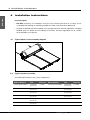
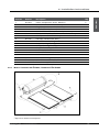
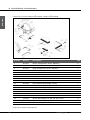
Installation Manual
Conergy TS
Open and Closed Systems
www.conergy.com.au
Table of Contents
1
Installer Information
2
1.1
The environmental benefits
2
1.2
Why Conergy?
2
1.3
How does the system work?
2
1.4
Conergy TS model number explained
4
1.5
Important safety information
5
1.6
If the customer is away for a period of time
5
1.7
Water discharge through the pressure valve
5
Troubleshooting
6
2
2.1
Low solar energy input
6
2.2
Solar collector shading
6
2.3
Booster system not operating
6
2.4
Excessive water discharge from the valves?
6
2.5
Using more hot water than anticipated?
6
3
System Maintenance
7
4
Installation Instructions
8
4.1
Typical open circuit assembly diagram
8
4.2
Typical system assembly
8
4.3
Connection and mounting part kits
9
4.4
Roof location selection
9
4.5
Supplementary heat sources
10
4.6
Common installation procedure
10
4.7
System installation
11
4.8
System diagrams and components
12
4.9
Plumbing connections - Open Circuit models
21
4.10
Plumbing connections – Closed Circuit models
22
4.11
Draining the storage tank
23
4.12
Filling the Closed Circuit jacket
23
4.13
Electrical installation instructions
25
4.14
Gas (AES) installation instructions
26
5
Commissioning & Customer Hand Over
27
6
ANNEX - Mounting frame for flat roof
28
Conergy TS
Installation Manual
ENGLISH
Table of Contents
1 Installation Information
ENGLISH
1 Installation Information
You are installing one of the most advanced solar water heaters in the world. This manual provides
you with the essential information needed to install the Conergy Thermosiphon System correctly.
Please read it carefully and follow all the instructions. We hope you find the following information
useful.
1.1
The environmental benefits
A Conergy solar water heater is an excellent and economic energy solution. By using the sun’s heat
to heat our water, we cut down on the amount of fossil fuels needed to be burnt to supply electricity
to do the same.
1.2
Why Conergy?
Conergy offers Australia’s largest range of renewable energy products and our company operates
in 25 countries on 5 continents. Our products are used in 100 000’s of Solar Home Systems for Hot
Water and Solar Electricity worldwide and we offer the leading products in this technology.
Before you can sell in Australia, or achieve any of the State or Federal Government rebates, your
product must comply with the rigorous Australian Standards for solar water heaters. Our products
comply with all these standards. The Federal Government Renewable Energy Certificate program,
called RECs, is an indication of solar efficiency. If you compare any of the Conergy products with
an equal competitor model, you will find that Conergy systems often achieve more RECs than our
competitors.
1.3
How does the system work?
Under normal operating conditions the potable water within the potable storage tank is heated by
the solar collectors. For example, in an open circuit system where the household hot water is in the
collector circuit, cold water is pushed downwards via the long external pipe from the storage tank to
the bottom of the solar collector. As the water is heated in the absorber by the sun, it rises to the top
of the collector then travels through the short external pipe into the storage tank.
The Conergy TS solar water heater is supplied in kit form so that the installer can assemble and
connect the solar water heater in various configurations to suit the installation location and user
requirements. Typically the kit contains the four main components of your solar water heater system
which are the potable water storage tank, the solar collector(s), the Ancillary Energy Support (AES)
System and the parts box, containing pipes fittings and mounting rails to interconnect and mount the
system. Please note the AES system can be either electric or gas operated dependent on the model
purchased.
Conergy TS
Installation Manual
1 Installation Information
Storage Tank & Solar Collectors
ENGLISH
1.3.1
Conergy TS 300 litre vitreous enamel tank
LC collector
The potable water storage tank is used to store the heated water ready for household use. It is
constructed using high quality vitreous enamel lined low carbon steel to provide long life. The
tank is insulated with a high density polyurethane material to ensure minimal heat losses and
maximmum structural strength.
The solar collectors contain a multi tube copper water way system bonded to a solar absorber
plate, the combination of which collects solar energy and transfers it to the fluid within the collector
circuit. The absorber plate system is enclosed in an insulated metal casing covered with a high
strength toughened glass sheet that protects the absorber system from physical damage.
1.3.2
Ancillary Energy Support (AES) - Booster System
Electricity and gas are the two options for the AES system. Please assist the customer in choosing
the most suitable AES system type. An electric Ancillary Energy Support (AES) system uses an
electric element to heat part of the stored household water on those occasions when there is
reduced solar energy available e.g. cloudy days.
The electricity supply to the electric element within the storage tank is automatically controlled
by an internal thermostat which will only allow the electric element to operate if the storage tank
water temperature falls below 60 °C and will, even then, only consume electricity until the water
temperature is increased to 60 °C at which stage it turns off automatically.
Conergy TS
Installation Manual
1 Installation Information
ENGLISH
For gas AES systems the electric element in the storage tank is not connected to an electricity
supply. Instead a continuous flow gas water heater is fitted adjacent to the storage tank and in
series with the hot water supply from the storage tank and the household hot water pipe system.
As the hot water from the solar storage tank passes through the gas heater its temperature is
automatically monitored. If the temperature is below 60 °C the gas heater will add the heat required
to deliver hot water of at least 60 °C. If the water temperature is above 60 °C the gas heater is
programmed not to ignite.
1.4
Conergy TS model number explained
The model number of the system is divided into sections to describe the system which you have
installed. For example: TS300/4/0/E24/V/E20SB.
The first two digits are used to determine the system type eg. TS300/4/O/E24/V/E20SB. TS is a
thermosiphon system.
The next three digits are used to determine the tank storage volume eg. TS300/4/O/E24/V/E20SB.
In the example 300 indicates that the storage volume is a nominal 300 litres. 180 would indicate a
nominal storage volume of 180 litres.
The fourth digit indicates the nominal collector surface area eg. TS300/4/O/E24/V/E20SB. In the
example 4 indicates 4m2 and 6 would indicate 6m2.
The next figure indicates the tank model type eg. TS300/4/O/E24/V/E20SB. In the example O indicates
an open circuit tank and a C would indicate a closed circuit tank.
The next figures indicate the AES model type eg. TS300/4/O/E24/V/E20SB. In the example E24
indicates an electric 2.4kW AES a G21 would indicate a 21 litre/min gas AES.
The next figure indicates the tank construction eg. TS300/4/O/E24/V/E20SB. In the example V
indicates a vitreous enamelled tank and an S would indicate a stainless steel tank.
The final 5 figures indicate the Collector model eg. TS300/4/O/E24/V/E20SB. In the example the
collectors are model E20SB. Other models are E20BC, E25BC or F20LC.
Conergy TS
Installation Manual
1 Installation Information
Important safety information
|
All water heaters have the ability to produce hot water very quickly. To reduce the risk of scald
injury it is recommended that a temperature control valve be fitted to the hot water supply pipe
work. This valve should be checked at regular intervals to ensure its operation and settings remain
correct. Please check that the pressure & temperature relief valve relief pipe is not located where
it can cause damage if hot water is discharged.
|
This water heater is not intended for use by young children or infirm persons without supervision.
Young children should always be supervised to ensure that they do not play with hot water taps
or the water heater.
Hydrogen gas can accumulate!
If the hot water system is not used for two weeks or more, a quantity of hydrogen gas, which is highly
flammable, may accumulate in the water heater. To dissipate this gas safely, it is recommended that
a hot tap be turned on for several minutes at a sink, basin or bath but not a dishwasher, clothes
washer, or other appliance. During this procedure there must be no smoking, open flame or any other
electrical appliance operating nearby. If hydrogen is discharged through the tap, it will probably make
an unusual noise as with air escaping. Do not place hands or any part of your body beneath the tap
during this procedure.
1.6
If the customer is away for a period of time
If the system is not to be used for a period of a week or more during the summer months it is advisable
to turn off the electricity supply to the booster and if practical, cover the solar collectors. If the solar
collectors are not covered there is a possibility that the high temperature valve in the storage tank
may open and disperse small amounts of hot water for a short period to reduce the storage tank
temperature while you are away. This is a normal function and does not harm the system.
1.7
Water discharge through the pressure valve
All Conergy solar water heaters have two pressure valves located within the system configuration.
The cold water expansion valve, located in the cold water supply pipe, may release a small amount
of water from time to time during the heating cycle of the system. The water discharge is water
expanding due to the heating process. Normally the discharge will be less than 10 litres per day.
The pressure & temperature valve, located on the storage tank, may also release a small expansion
discharge.
Conergy TS
Installation Manual
ENGLISH
1.5
2 Troubleshooting
ENGLISH
2
Troubleshooting
What to check for during service calls
If there is not enough hot water we recommend that the following points are considered as part of the
service call. The most obvious reasons for a lack of hot water could be one of the following:
2.1
Low solar energy input
If there have been prolonged periods of cloud or winter is approaching, it may be necessary to
reconsider the permitted boosting time for time-clock controlled systems or to turn on the booster
for systems with a booster isolation switch.
2.2
Solar collector shading
Often trees or other buildings can shade the solar collectors or there can be a dirt build-up on the
glass cover. Trees should be cut back if possible or the system relocated if removal of the shading
is not possible in the present location. If the glass is dirty this should be cleaned with any normal
domestic glass cleaner. If rainwater collection occurs from the same roof on which the solar water
heater is located, do not use chemical cleaning agents to clean the collectors. Any spillage of these
onto the roof could cause contamination of water in the rainwater tank.
2.3
Booster system not operating
For electric systems the fuse or circuit breaker supplying the AES System should be checked. If the
time clock (where fitted) and the fuse or circuit breaker are operational and the water is cold, you can
turn the booster isolator on and off to see if the electricity meter speed changes. If there is no change
in speed, it indicates there may be a booster problem, which would need to be investigated.
For gas systems the gas and electric supplies to the gas heater should be checked to ensure they are
both on. If water temperature from the gas heater is below 60 °C and both supplies are on and the
gas heater does not ignite there may be a problem, which would need to be investigated further.
2.4
Excessive water discharge from the valves?
If there is a discharge of more than 10 litres per day from any of the systems valves, it indicates there
may be a problem with the valve or an increased water supply pressure.
2.5
Using more hot water than anticipated?
Often the hot water usage of showers, washing machines and dishwashers is underestimated by
the customer. Review these appliances to determine if the daily usage is greater than the storage
volume of the water heater. Depending on the model, our TS system tanks contain 180 or 300 litres
of hot water therefore if the customer’s usage is greater than 300 litres within a short period of time,
there may be periods where the water temperature is slightly lower than normal. It is also advisable
to inspect hot water tap washers etc. for leakage and replace if necessary.
Conergy TS
Installation Manual
3 System Maintenance
System Maintenance
The Conergy system is designed such that there is little to do regarding system maintenance. Should
you decide that you want to inspect the roof mounted system it is essential that you use all safety
devices required to ensure your personal safety.
Glass cleaning usually occurs by natural rainfall, however if the installation is in an industrial (or
similar) area with high levels of airborne particles then a qualified person can clean the collector
glass with normal window cleaning chemicals and equipment. If rainwater collection occurs from the
same roof on which the solar water heater is located, do not use chemical cleaning agents to clean
the collectors. Any spillage of these onto the roof could cause contamination of water in the rainwater
tank.
The lever on the relief valves should be operated at least every six months. Failure to do so may result
in failure of the tank. If water does not discharge freely from the valves they should be checked and
possibly replaced. The relief valves and relief valve drain lines must not be blocked. Some water may
discharge during each heating cycle.
Every five years all safety valves should be replaced to ensure continued life and operational safety
of the system. In locations where the potable water has a Total Dissolved Solids (TDS) of greater than
600 ppm it is recommended to replace all safety valves every 3 years.
The high quality vitreous enamel lined low carbon steel tanks have a sacrificial anode for long tank
life. This anode should be inspected every few years and be replaced when it has worn out. As a
minimum it is recommended that the anode be changed every 5 years.
Conergy TS
Installation Manual
ENGLISH
3
4 Installation Instructions
ENGLISH
4
Installation Instructions
Important Notes
| DO NOT commence an installation until you have satisfied yourself that all safety issues
associated with working on and lifting components onto a roof have been addressed.
| All work associated with the installation must comply with local authority regulations including
AS/NZS 3500.4.2. Where these installation instructions and local regulations are in conflict,
local regulations must prevail.
4.1
Typical open circuit assembly diagram
4.2
Typical system assembly
The table below indicates the system components:
Module Number
Tank
Tank
Collector
TS180/2/0/E24/V/F20LC TS180/0/E24 1 x F20LC TS180/2/C/E24/V/E20BC
open circuit
Collector
Model Number
TS180/C/E24
closed circuit
1 x E20BC
TS180/2/0/E24/V/E20BC TS180/0/E24 1 x E20BC TS180/2/C/E24/V/E20SB open circuit
TS180/C/E24
closed circuit
1 x E20SB
TS180/2/0/E24/V/E20SB TS180/0/E24 1 x E20SB TS300/4/C/E24/V/E20BC open circuit
TS300/C/E24
closed circuit
2 x E20BC
TS300/4/0/E24/V/F20LC TS300/0/E24 2 x F20LC TS300/4/C/E24/V/E20SB open circuit
TS300/C/E24
closed circuit
2 x E20SB
TS300/4/0/E24/V/E20BC TS300/0/E24 2 x E20BC open circuit
TS300/4/0/E24/V/E20SB TS300/0/E24 2 x E20SB open circuit
Conergy TS
Installation Manual
4 Installation Instructions
Connection and mounting part kits
ENGLISH
4.3
The table below indicates the connection and mounting kits required for each model system:
4.4
Module Number Parts Kit
TS180/2/O/E24/V/E20BC TS180/2/O/E24/V/E20SB
TS180/2/C/E24/V/E20BC TS180/2/C/E24/V/E20SB
TS180/2/O/E24/V/F20LC TS300/4/O/E24/V/E20BC TS300/4/O/E24/V/E20SB
TS300/4/C/E24/V/E20BC
TS300/4/C/E24/V/E20SB
TS300/4/O/E24/V/F20LC PK2050
PK2051
PK2052
PK2055
PK2056
PK2057
Roof location selection
There are five major factors to consider when selecting the solar water heater installation location:
|
For optimum performance the solar collectors need to face the equator (in Southern hemisphere
this is north and in the Northern hemisphere this is South). Installation on angles of up to 45°
away from the equator do not have a major effect on the annual solar output, consequently roof
locations which face less than 45° away from the equator are acceptable. If the collectors are
installed with an east facing bias the best solar input is achieved in the morning and if there is a
west facing bias the best solar input is in the afternoon.
|
Careful site inspection is required to ensure the selected location is not subjected to shading
from adjacent trees or buildings throughout the day, but particularly between 9am and 3pm, the
highest solar input times. Shadows are longer in winter than in summer so a site that is free of
shadows from adjacent objects in summer may have some shadows in winter.
|
The solar water heater should be located as close as possible to the location which uses the most
hot water eg. bathroom or kitchen. This is to reduce energy losses which may occur if the pipe
work between the solar water heater and the point of usage is too long.
|
To achieve optimum performance the solar water heater should be installed on a roof pitch of
greater than 8° and less than 30°. Installations on a roof where the roof pitch is greater than 30°
will require additional support at the storage tank to prevent it moving downward during and after
installation. If the roof pitch is less than 8° the system will require a mounting frame to increase
the pitch above 8°. Installations below 8° do not thermosiphon effectively and the collector glass
will not self clean during rainy periods.
Conergy TS
Installation Manual
4 Installation Instructions
ENGLISH
|
4.5
The roof system must be carefully inspected to ensure it can support the systems weight once it is
filled with water. Particular care must be taken where the front foot of the storage tank is located.
Typically the tank front foot should be located over a tile batten, purlin or similar for maximum
strength. If the roof can not support the load, additional bracing must be installed before the solar
water heater is installed.
Supplementary Heat Sources
If a supplementary heat source is connected to the storage tank the maximum energy input can be
not more that 10 kW including the electrical element. Where greater input is required a pressure and
temperature relief valve with a higher kW rating is to be fitted to the storage tank.
Where stove coils are used for supplementary heating the water must be connected in an open
vented manner. Refer to Australian Standard AS3500 for more details on acceptable connection
solutions.
Any supplementary heat source must be limited such that the maximum tank temperature is 80 °C.
For the interconnecting details e.g. pipe work of your specific model/configurations please check the
assembly drawings in the following pages.
4.6
4.6.1
Common installation procedure
Determining mounting location
The starting point for the installation is the storage tank front foot. The storage tanks front foot
must be located over a tile batten or purlin for maximum strength. The batten or purlin selected
must be located at least 2.4 metres up from the roof’s lower edge and 1 metres down from the
roof’s ridge line so that the ridge caps are not disturbed.
1. Place the tank into position with its front foot centrally over the selected tile batten. The tank
should be installed after the collectors are installed. The tank centre should be installed over
rafters/trusses evenly so as to spread the tank weight over an even area of the roof.
2. Measure down the roof from the right side front edge of the front foot a distance of 2030 mm
and make a mark on the roof tile. This position (Point 2 of mounting location) will be the bottom
edge of the collector mounting rail.
10
Conergy TS
Installation Manual
4 Installation Instructions
System Installation
Please note that the detail letters referred to in the installation text refer to the diagrams on page 12
and onwards.
1.
Place one end of the bottom collector mounting rail (Detail E) at the location marked before (refer
to point 2) and lay horizontally across the roof to the left.
2. Locate two roof trusses which are under the collector mounting rail (as near as possible to the
outer edges of the rail). Slide two collector straps (Detail E) onto the collector mounting rail where
the trusses pass under the mounting rail.
3. Adjust the mounting rail so that it is horizontally across the roof then raise it 5 – 10 mm on the
right side.
4. Screw fix the collector straps to the roof trusses using the prepunched holes in the collector
straps.
5. Take the first solar collector and place it on the collector mounting rail, at the left most end.
6. Loosely fit the two collector connectors (Detail D) to the two copper tube spigots on the right
side of collector.
7.
Take the second collector and place it onto the right hand side of the collector mounting rail.
8. Now, slide collector toward the first collector until the two copper tube spigots of that collector
slide fully home into the collector connectors already fitted to collector.
9. Tighten the compression nuts of the collector connector fittings (Detail D) taking care not to
twist the copper tubes of the collector. Make sure you use correctly sized spanners and that
the centre nut is held steady whilst the compressing nuts are tightened.
10. Move the two collectors so that they are centrally located on both the collector mounting rail and
the tank.
11. Using 4 of the self drilling screws supplied screw fix the collector rail to the collectors as shown
in details D and E. Finally using 2 of the self drilling screws supplied and screw fix the collector
straps to the collector rail and collectors as shown in Detail E.
12. Slide a Compression Plug assembly (Detail A) to the top left corner of the collector array. Tighten
the assembly taking care not to twist the copper tubes of the collector.
13. For open circuit models slide a Compression Plug assembly (Detail E) to the bottom right corner
of the collector array. Tighten the assembly taking care not to twist the copper tubes of the
collector.
14. For closed circuit models slide the Fill Fitting assembly (Detail E) to the bottom right corner of the
collector array. Tighten the assembly taking care not to twist the copper tubes of the collector.
15. Fit the Cold Pipe connection pipe (Detail A and C) to the bottom left corner of the collector array
and the storage tank tube fitting as shown on the model configuration drawing following.
16. Install the Hot Pipe assembly as shown in Detail B between the top right corner of the collector
array and the storage tank tube fitting as shown in Detail B. When the assembly is in place tighten
all fittings.
17. Insert the 850 kPa P&T valve supplied with the Parts Kit and insert it into the valve port in the
storage tank as shown in Detail A.
Conergy TS
Installation Manual
11
ENGLISH
4.7
4 Installation Instructions
ENGLISH
18. For closed circuit models insert the 100 kPa closed circuit pressure relief valve into the ½” tank
socket as shown in Detail A. Note this valve is not used on open circuit models.
19. Using the straps supplied with the Parts Kit place one into each side of the tank front foot as
shown in Detail A. back leg so that they are over a rafter then screw fix in place to the rafter to
secure the tank in place. Take the straps under the tank and screw fix to the roof rafter.
20. Finally take the tank clamp and bolt it to the tank strap behind the tank so that the tank clamp
secures the tank to the tank strap. To complete the security screw fix the 2 tank clamps to the
tank using the 2 self drilling screws provided.
4.7.1
4.8
4.8.1
Flat Roof Installations
For flat roof installations a special mounting frame is required (For more information see Annex at
end of manual) Once the frame is mounted please follow the installation as outlined above.
System diagrams and components
*
Model TS300/4/O/XX/X/F20LC
* Represents all AES and tank options.
12
Conergy TS
Installation Manual
4 Installation Instructions
ENGLISH
*
Components of model TS300/4/O/XX/X/F20LC
Item No.
Part No.
Description Qty
1
2
3
4
5
6
7
8
9
10 11 12 13 14 15 16 17 18 2LC-T-ZA 60-1002 60-1003 60-1004 60-1056 60-1083 60-1122 60-1129 60-1130 60-3028 60-4000 60-4004 60-4011 75-4000 75-4001 75-4002 75-4016 S300/O/KE Collector, Solar, F20LC Union, Compression, 22mm, Sub-Assy Union, RP3/4” - C22mm, Sub Assy Plug, Compression, 22mm, Sub Assy Valve, P&T, 850kPa Union, Collector Elbow, Thermosiphon, Sassy Union, Cold Inlet Tee, RP3/4”xC3/4”xC22mm, Extended, SAssy Cold Pipe, 304/LC/O/XX, SAssy Hot Pipe, 304/LC/O/XX, SAssy Rail, Collector, Steel Angle, 2 Panel Strap, Mounting, Tank, Type A Clamp, Mounting, Tank, Type A Strap, Collector, Type C Nut, Hex, SS, M8 x 1.25 Washer, Plain, Stainless Steel, M8 Set Screw, Hex, SS, M8 x 1.25 x 20 Screw, Self Drilling, Pan, SS, CR, #8 x 13mm Tank, Assembly, TS300/O/V 2
2
1
2
1
1
1
1
1
1
2
2
2
2
2
2
8
1
* Represents all AES and tank options.
Conergy TS
Installation Manual
13
4 Installation Instructions
*
*
Models TS300/4/O/XX/X/E20BC, TS300/4/O/XX/X/E20SB
ENGLISH
4.8.2
Components
*
* Represents all AES and tank options.
14
Conergy TS
Installation Manual
4 Installation Instructions
4.8.3
Part No.
Description Qty
1
2
3
4
5
6
7
8
9
10 11 12 13 14 15 16 17 18 60-1002 60-1003 60-1004 60-1056 60-1086 60-1121 60-1125 60-1128 60-3028 60-4000 60-4004 60-4011 75-4000 75-4001 75-4002 75-4016 E20 S300/O/KE Union, Compression, 22mm, Sub-Assy Union, RP3/4” - C22mm, Sub Assy Plug, Compression, 22mm, Sub Assy Valve, P&T, 850kPa Union, Collector Elbow 2, Thermosiphon, SAssy Union, Cold Inlet Tee, RP3/4”xC3/4”xC22mm, SAssy Cold Pipe, 304/BC/X/XX, SAssy Hot Pipe, 304/BC/O/XX, SAssy Rail, Collector, Steel Angle, 2 Panel Strap, Mounting, Tank, Type A Clamp, Mounting, Tank, Type A Strap, Collector, Type C Nut, Hex, SS, M8 x 1.25 Washer, Plain, Stainless Steel, M8 Set Screw, Hex, SS, M8 x 1.25 x 20 Screw, Self Drilling, Pan, SS, CR, #8 x 13mm Solar Collector, E20BC, E20SB Tank, Assembly, TS300/O/V 2
1
2
1
1
1
1
1
1
2
2
2
2
2
2
8
2
1
ENGLISH
Item No.
*
*
Models TS300/4/C/XX/X/E20BC,
TS300/4/C/XX/X/E20SB
* Represents all AES and tank options.
Conergy TS
Installation Manual
15
4 Installation Instructions
ENGLISH
*
*
Components of model TS300/4/C/XX/X/E20BC, TS300/4/C/XX/X/E20SB
Item No.
Part No.
Description Qty
1
2
3
4
5
6
7
8
9
10 11 12 13 14 15 16 17 18 19 60-1002 60-1003 60-1004 60-1009 60-1056 60-1119 60-1120 60-1125 60-1126 60-3028 60-4000 60-4004 60-4011 75-4000 75-4001 75-4002 75-4016 E20 S300/C/KE Union, Compression, 22mm, Sub-Assy Union, RP3/4” - C22mm, Sub Assy Plug, Compression, 22mm, Sub Assy Valve, Caleffi, 100kPa Valve, P&T, 850kPa Union, Fill Fitting, 22mm, SAssy Union, Collector Elbow 3, Thermosiphon, SAssy Cold Pipe, 304/BC/X/XX, SAssy Hot Pipe, 304/BC/C/XX, SAssy Rail, Collector, Steel Angle, 2 Panel Strap, Mounting, Tank, Type A Clamp, Mounting, Tank, Type A Strap, Collector, Type C Nut, Hex, SS, M8 x 1.25 Washer, Plain, Stainless Steel, M8 Set Screw, Hex, SS, M8 x 1.25 x 20 Screw, Self Drilling, Pan, SS, CR, #8 x 13mm Solar Collector, E20BC, E20SB Tank Assembly, TS300/C/V 2
2
1
1
1
1
2
1
1
1
2
2
2
2
2
2
8
2
1
* Represents all AES and tank options.
16
Conergy TS
Installation Manual
4 Installation Instructions
*
Model TS180/2/O/XX/X/F20LC
ENGLISH
4.8.4
*
Components
* Represents all AES and tank options.
Conergy TS
Installation Manual
17
ENGLISH
4 Installation Instructions
4.8.5
Item No.
Part No.
Description Qty
1
2
3
4
5
6
7
8
9
10 11 12 13 14 15 16 17 2LC-T-ZA 60-1003 60-1004 60-1056 60-1083 60-1121 60-1131 60-1134 60-3030 60-4000 60-4004 60-4011 75-4000 75-4001 75-4002 75-4016 S180/O/KE Solar Collector F20LC Union, RP3/4” - C22mm, Sub Assy Plug, Compression, 22mm, Sub Assy Valve, P&T, 850kPa Union, Collector Elbow, Thermosiphon, SAssy Union, Cold Inlet Tee, RP3/4”xC3/4”xC22mm, SAssy Cold Pipe, 182/BC/C/XX, SAssy Hot Pipe, 182/BC/O/XX, SAssy Rail, Collector, Steel Angle, 1 Panel Strap, Mounting, Tank, Type A Clamp, Mounting, Tank, Type A Strap, Collector, Type C Nut, Hex, SS, M8 x 1.25 Washer, Plain, Stainless Steel, M8 Set Screw, Hex, SS, M8 x 1.25 x 20 Screw, Self Drilling, Pan, SS, CR, #8 x 13mm Tank Assembly, TS180/O/V 1
1
2
1
1
1
1
1
1
2
2
2
2
2
2
6
1
*
*
Models TS180/3/O/XX/X/E20BC,
TS180/2/O/XX/X/E20SB
* Represents all AES and tank options.
18
Conergy TS
Installation Manual
4 Installation Instructions
ENGLISH
*
*
Components of model TS180/3/O/XX/X/E20BC, TS180/3/O/XX/X/E20SB
Item No.
Part No.
Description Qty
1
2
3
4
5
6
7
8
9
10 11 12 13 14 15 16 17 60-1003 60-1004 60-1056 60-1083 60-1121 60-1133 60-1134 60-3030 60-4000 60-4004 60-4011 75-4000 75-4001 75-4002 75-4016 E20 S180/O/KE Union, RP3/4” - C22mm, Sub Assy Plug, Compression, 22mm, Sub Assy Valve, P&T, 850kPa Union, Collector Elbow, Thermosiphon, SAssy Union, Cold Inlet Tee, RP3/4”xC3/4”xC22mm, SAssy Cold Pipe, 182/BC/O/XX, SAssy Hot Pipe, 182/BC/O/XX, SAssy Rail, Collector, Steel Angle, 1 Panel Strap, Mounting, Tank, Type A Clamp, Mounting, Tank, Type A Strap, Collector, Type C Nut, Hex, SS, M8 x 1.25 Washer, Plain, Stainless Steel, M8 Set Screw, Hex, SS, M8 x 1.25 x 20 Screw, Self Drilling, Pan, SS, CR, #8 x 13mm Solar Collector, E20BC, E20SB Tank Assembly, TS180/O/V 1
2
1
1
1
1
1
1
2
2
2
2
2
2
6
1
1
* Represents all AES and tank options.
Conergy TS
Installation Manual
19
4 Installation Instructions
*
*
Models TS180/3/C/XX/X/E20BC,
TS180/2/C/XX/X/E20SB
ENGLISH
4.8.6
Components
*
* Represents all AES and tank options.
20
Conergy TS
Installation Manual
4 Installation Instructions
4.9
4.9.1
Part No.
Description Qty
1
2
3
4
5
6
7
8
9
10 11 12 13 14 15 16 17 18 60-1003 60-1004 60-1009 60-1056 60-1083 60-1119 60-1131 60-1132 60-3030 60-4000 60-4004 60-4011 75-4000 75-4001 75-4002 75-4016 E20 S180/C/KE Union, RP3/4” - C22mm, Sub Assy Plug, Compression, 22mm, Sub Assy Valve, Caleffi, 100kPa Valve, P&T, 850kPa Union, Collector Elbow, Thermosiphon, SAssy Union, Fill Fitting, 22mm, SAssy Cold Pipe, 182/BC/C/XX, SAssy Hot Pipe, 182/BC/C/XX, SAssy Rail, Collector, Steel Angle, 1 Panel Strap, Mounting, Tank, Type A Clamp, Mounting, Tank, Type A Strap, Collector, Type C Nut, Hex, SS, M8 x 1.25 Washer, Plain, Stainless Steel, M8 Set Screw, Hex, SS, M8 x 1.25 x 20 Screw, Self Drilling, Pan, SS, CR, #8 x 13mm Solar Collector, E20BC, E20SB Tank Assembly, TS180/C/V 2
1
1
1
2
1
1
1
1
2
2
2
2
2
2
6
1
1
ENGLISH
Item No.
Plumbing connections - Open Circuit Models
Cold water connection
A check valve and a stop cock must be fitted to the cold water supply pipe work.
1.
Connect the cold water supply to the end of the ¾” BSP female thread of the Tee piece in the
cold down pipe assembly (Detail A).
It is mandatory that a check valve and stop cock are fitted to the cold water supply pipe work.
2. Where the water supply pressure is greater than 550 kPa, a 500 kPa pressure limiting valve
must be fitted to limit the supply pressure.
4.9.2
Cold water expansion relief valve
Fit the 700 kPa pressure relief valve supplied in the Parts Box in the cold water supply pipe after
the check valve, stop cock and (if required) pressure limiting valve assembly.
4.9.3
Hot water connection
Use the ¾” BSP x 22mm fitting supplied in the parts kit to connect the hot water supply to the
storage tank outlet connection (Detail A) adjacent the P&T valve and marked with a blue disc.
Conergy TS
Installation Manual
21
4 Installation Instructions
ENGLISH
4.9.4
Pressure & temperature relief valve (P&T valve)
Remember this valve can discharge very hot water, so carefully consider its location. Never
discharge onto a solid surface like concrete.
1. Fit the 850 kPa/95°C (10 kW) pressure & temperature relief valve supplied in the parts box into
the ½” brass tank socket adjacent to the hot outlet tube as shown in (Detail A).
2. Ensure that the drain line from the pressure and temperature relief has a continuous downslope
and falls away from the valve and towards the ground level to a safe location, terminating above
the ground level. Please ensure that the drain is installed in a place where it cannot be affected
by freezing conditions (per AS3500).
4.10
4.10.1
Plumbing connections – Closed Circuit Models
Cold water connection
1. Fit the ¾” BSP x 22 mm fitting supplied in the parts kit to the copper tube in the storage tank
marked with the blue disc (Refer Detail A). Then connect the cold water supply to the ¾” BSP
thread of that fitting.
2. It is mandatory that a check valve and stop cock are fitted to the cold water supply pipe work.
Where the water supply pressure is greater than 550 kPa, a 500 kPa pressure limiting valve
must be fitted to limit the supply pressure.
4.10.2
Cold water expansion relief valve
Fit the 700 kPa pressure relief valve supplied in the Parts Box in the cold water supply pipe after
the check valve, stop cock and (if required) pressure limiting valve assembly.
4.10.3
Hot water connection
Use the ¾” BSP x 22mm fitting supplied in the parts kit to connect the hot water supply to the
storage tank outlet connection (Detail A) adjacent the P&T valve and marked with a blue disc.
4.10.4
Pressure & temperature relief valve (P&T valve)
Remember this valve can discharge very hot water, so carefully consider its location. Never
discharge onto a solid surface like concrete.
1. Fit the 850 kPa/95°C (10 kW) pressure and temperature relief valve supplied in the parts box
into the ½” brass tank socket adjacent to the hot outlet tube as shown in (Detail A).
2. Ensure that the drain line from the pressure & temperature relief has a continuous downslope
and falls away from the valve and towards the ground level to a safe location, terminating above
the ground level. Please ensure that the drain is installed in a place where it cannot be affected
by freezing conditions (per AS3500).
22
Conergy TS
Installation Manual
4 Installation Instructions
4.11
Draining the storage tank
ENGLISH
To drain the water from the storage tank the following procedure is to be followed:
1. Turn off and isolate the power supply to the electrical element.
2. Turn off the water supply to the water heater.
3. Release excess pressure from the tank by manually opening the pressure & temperature relief
valve.
4. Disconnect the cold water supply pipe connection to the tank.
5. Fit a ½” flexible drain pipe to the cold connection at the tank. Place the open end of the drain
hose in a location where it is safe for the hot water to drain away from the tank.
6. Manually open the pressure & temperature relief valve which will allow air into the tank and the
water within the tank will flow out via the flexible drain pipe fitted to the cold inlet connection.
Hold the valve open until the tank is empty.
4.12
Filling the Closed Circuit jacket
Risk of damage to the elements can occur if the installation sequences are not maintained.
4.12
|
|
|
When filling the jacket with glycol it is essential that the main tank is filled with water and pressurised
prior to filling the closed circuit.
Do not apply power to the electric booster element before the tank is filled with water.
Do not fill the closed circuit system with any toxic solution. Only use the solar transfer fluid as
specified by your Conergy TS distributor. There is a real risk to public health if the wrong glycol
solar solution is used.
Approved Solar Transfer Fluid details
Name: St-5 Solar Transfer Fluid
Description: Propylene Glycol
Appearance: Red Liquid
When you are ready to fill the system please have the following equipment ready to fill and test the
system:
|
|
|
|
|
1 x 25 litre container
1 x 4 metre length of ½” (15mm)
1 x Pressure Test Block
1 x Bicycle Pump
1 x 4.5 litre bottle ST-5 solar transfer fluid supplied with the system
Conergy TS
Installation Manual
23
4 Installation Instructions
ENGLISH
4.12.1
Fill and test information and procedure
|
Cover Collectors for this procedure to prevent pressure variation due to thermal activity in the
collectors.
|
The solar transfer fluid is of food grade and non toxic. However, care must be taken when
handling not to spill or accidentally consume. Always use the solar transfer fluid as specified
by Conergy and outlined above.
|
Every care must be taken to ensure that in installations where rain water is being collected from
the same roof, any spilt ST-5 solution is cleaned up immediately so that the ST-5 solution does
not contaminate the water in the rain water storage tank.
1. Remove the 100 kPa jacket relief valve from the tank socket. See Detail A for the loaction of
this valve.
2. Connect a ½” (15 mm) flexible hose to the fill tap located at the bottom
right side of the collector array. See Detail D for the location and the
photo to the right for detail.
3. With the aid of a funnel and hose connected to the fill tap, pour the
contents of the heat transfer fluid container into the funnel (4.5 litres)
then add drinking grade water until the fluid flows from the 100 kPa
jacket relief valve socket in the tank. See drawing below for the
detail.
Detail D - Fill tap
4. Close the fill tap and insert the pressure test block into the tank’s 100
kPa jacket relief valve socket. To the right is a photo of the pressure
test block.
Pressure test block
Jacket relief valve
(Detail A)
Funnel
Hose
Fill tap
(Detail D)
24
Conergy TS
Installation Manual
4 Installation Instructions
ENGLISH
5. Using a bicycle pump or similar connected to the jacket relief valve,
as shown to the right, pressurise the system to 120 kPa.
6. Check all fittings for signs of leakage and tighten if required.
7. Check over a 10 minute period that the pressure on the test gauge
remains unchanged.
8. Once it is seen that the circuit is free from leakage release the
pressure in the system through the pressure test block valve fitting
then unscrew the pressure test block from the tank socket.
9. Refit the 100 kPa jacket relief valve into the tank socket from which
the pressure test block was removed.
10. The system is now operational and the covers can be removed from
the collectors.
The heat transfer fluid should be checked every five (5) years and replaced if necessary.
4.13
Electrical installation instructions
Note
Risk of damage to the elements can occur if the installation sequences are not maintained.
4.13.1
|
All electrical work must comply with local regulations.
|
All electrical work must be conducted by a suitability licensed electrician.
Electrical Connection for Electric AES Systems
|
The electric element is only connected in models using an electric AES system. No connection
is made to the electric element for gas AES systems.
|
The electrical booster requires a 220 – 250 volt single phase AC power supply with a capacity
suitable for the kilowatt rating of the element selected for the application. eg. a 2.4 kW element
requires a 10 amp supply capacity.
|
The power supply must be protected by an individual fuse or circuit breaker rated to suit the
booster size. The supply to the solar water heater can be operated directly from the switchboard
or via a remotely mounted switch or time clock as requested by the customer.
|
Final electrical connection at the solar water heater tank must be made via an electrical
disconnection device (eg isolator) and connected at the tank as follows: The earth wire is
connected to the earth stud marked with an earth symbol, the active wire connected to the
thermostat terminal marked (L) and the neutral wire is connected to the thermostat terminal
marked (N).
Do not turn on the power supply until the solar water heater has been filled with water
and pressurised. There is a risk of damage to the system if the installation sequence is
not followed.
Conergy TS
Installation Manual
25
4 Installation Instructions
Electrical Circuit Diagram
ENGLISH
4.13.2
/)#
,)6%
,
#9#,).'
4(%2-/34!4
%,%-%.4
4.13.3
4.14
.%542!,
.
%!24(
%
Electrical Connection for Gas AES Systems
For models using a gas AES system the electrician is required to install a domestic electrical
outlet socket adjacent to the gas heater location. The gas heater requires a 220-240 volt 50 Hz
powersupply and is rated at 0.47 amperes.
Gas (AES) Installation Instructions Note
Important note:
4.14.1
|
All gas work must comply with local regulations including AS5701/AG601 and AS/NZ 3500.4
|
All gas work must be conducted by a suitability licensed gas fitter.
|
Installation of the gas heater must be installed in accordance with the installation instructions
supplied with it .
|
Conergy systems only use approved Gas Heaters.
|
Particular attention must be given to the gas supply system to ensure the there is a sufficient gas
supply available to the gas heater when operating at full output burner rate.
Approved Gas Heater Models
Gas heater models used with Conergy solar water heater systems must be certified to all local
requirements, be automatic ignition and have full flame modulation.
Gas heaters other than this type must not be used with a Conergy solar water heater. Particularly
fixed pilot and fixed flame models must not be used under any circumstance.
Please refer to your local distributor for information on approved gas heater model.
26
Conergy TS
Installation Manual
5 Commissioning & Customer Hand Over
Commissioning & Customer Hand Over
When all connections have been completed the solar water heater can be filled with water.
|
Before turning on the cold water supply open one hot tap within the household to release air
from the system during the filling process. Do not leave the open tap unattended during the filling
process.
|
Turn on the cold water supply and wait for the system to fill.
|
When water flows from the open hot tap without air bursts then the hot tap can be closed. This
will now pressurise the solar water heater system.
|
Once the system is pressurised all connections on the water heater must be checked for leaks
and repaired if necessary.
|
When the system is proven water tight, power and gas can be applied to the AES system.
|
To test that the element is operational turn the circuit breaker in the switch board on and off, you
should see the power meters speed change during this action.
|
For gas AES systems turn on a hot water tap and the gas heater will ignite provided the water
temperature is less than 60 °C.
Customer Hand Over
The solar water heater is now fully operational.
Once the solar water heater is commissioned and you are confident it is operating correctly, complete
the installation details on the carbon copy sheet at the beginning of the owners manual. Please
remove the Conergy (blue) and the installer (pink) copy. Please hand the owner the Owners Manual
and Gas Heater Manual (if gas AES is used).
Before leaving the installation ensure that the customer is fully aware of the systems operation and
whom to contact should there be any questions in the future.
Thank you for installing our world class Conergy solar water heater.
Your Conergy Team
Conergy TS
Installation Manual
27
ENGLISH
5
6 ANNEX - Mounting frame for flat roof
ANNEX - Mounting frame for flat roof
ENGLISH
6
2BC = 2000mm
2B = 2000mm
2S = 2000mm
2SP = 2000mm
2LC = 1935mm
Tank
E
D
800
C
A
B
2660
1500
Note:
1. Ensure tank is located directly over vertical support.
28
Conergy TS
Installation Manual
Item No.
Article
Description No.
PK-1014
Qty
PK-2055, PK-2056,
PK-2057 Qty.
1
60-3000 Cross Brace, Unistrut P4000, 2 Panel Mounting Frames 2 -
2
60-3003 Bracket, 70, Mounting Frames 2
-
3
60-3004 Bracket, 90, Mounting Frames 2
-
4
60-3005 Base/Hypoteneuse, Unistrut P2000, Mounting Frames 4
-
5
60-3006 Upright, Unistrut P2000, Mounting Frames 2
-
6
60-3024 Bracket, 20, Mounting Frame 2
-
7
60-3028 Rail, Collector, Steel Angle, 2 Panel -
1
8
60-4004 Clamp, Mounting, Tank, Type A -
2
9
60-6007 Rail, Collector, Aluminium, 2 Panel 1
-
10 60-6008 Clamp, Collector Mount, Z 4
-
11 75-3009 Nut, Channel, ZP, M10 x 1.5 12 -
12 75-3010 Nut, Channel, ZP, M8 x 1.25 2
-
13 75-3028 Washer, Plain, ZP, M10 18 -
14 75-3030 Set Screw, Hex, ZP, 4.6, M10 x 1.5 x 25 18 -
15 75-3031 Nut, Hex, ZP, 4.6, M10 x 1.5 6
-
16 75-4000
Nut, Hex, SS, M8 x 1.25 4
2
17 75-4001 Washer, Plain, Stainless Steel, M8 4
2
18 75-4002 Set Screw, Hex, SS, M8 x 1.25 x 20 4
2
19 75-4016 Screw, Self Drilling, Pan, SS, CR, #8 x 13mm 4
8
Conergy TS
Installation Manual
29
ENGLISH
6 ANNEX - Mounting frame for flat roof
55-4008-REV1-0708
For further technical information,
please contact your Conergy state manager
Conergy Pty Ltd
Unit 6
44-48 O’Dea Avenue
Waterloo NSW 2017
Ph: 02 8507 2222
Email: [email protected]
www.conergy.com.au
100% recycled paper