1
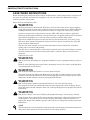
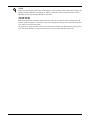
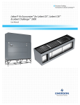
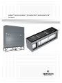
Liebert® Air Economizer™ for Liebert DS™ and Liebert CW™
User Manual
TABLE OF CONTENTS
IMPORTANT SAFETY INSTRUCTIONS . . . . . . . . . . . . . . . . . . . . . . . . . . . . . . . . INSIDE FRONT COVER
1.0
PRODUCT DESCRIPTION . . . . . . . . . . . . . . . . . . . . . . . . . . . . . . . . . . . . . . . . . . . . . . . . . . .3
1.1
General Product Information. . . . . . . . . . . . . . . . . . . . . . . . . . . . . . . . . . . . . . . . . . . . . . . . . . . 3
1.1.1
Customer-Supplied Equipment and Ductwork. . . . . . . . . . . . . . . . . . . . . . . . . . . . . . . . . . . . . . 4
1.2
Equipment Inspection . . . . . . . . . . . . . . . . . . . . . . . . . . . . . . . . . . . . . . . . . . . . . . . . . . . . . . . . 5
1.3
Equipment Handling . . . . . . . . . . . . . . . . . . . . . . . . . . . . . . . . . . . . . . . . . . . . . . . . . . . . . . . . . 5
1.3.1
1.3.2
Handling the Liebert Air Economizer With Skid . . . . . . . . . . . . . . . . . . . . . . . . . . . . . . . . . . . . 5
Moving the Liebert Air Economizer With a Forklift . . . . . . . . . . . . . . . . . . . . . . . . . . . . . . . . . 5
1.4
Unpacking the Liebert Air Economizer. . . . . . . . . . . . . . . . . . . . . . . . . . . . . . . . . . . . . . . . . . . 6
2.0
INSTALLATION . . . . . . . . . . . . . . . . . . . . . . . . . . . . . . . . . . . . . . . . . . . . . . . . . . . . . . . . . .7
2.1
General Considerations . . . . . . . . . . . . . . . . . . . . . . . . . . . . . . . . . . . . . . . . . . . . . . . . . . . . . . . 7
2.2
Install the Liebert Air Economizer—Preliminary Steps . . . . . . . . . . . . . . . . . . . . . . . . . . . . . 7
2.2.1
2.2.2
2.2.3
2.3
Position the Liebert Air Economizer over a Liebert CW™ . . . . . . . . . . . . . . . . . . . . . . . . . . . . . 7
Secure the Liebert Air Economizer to the Liebert CW™—CW026-114 . . . . . . . . . . . . . . . . . . . 8
Attach the Liebert Air Economizer to a Liebert CW146/181 or Liebert DS028-105 . . . . . . . 10
Wiring the Liebert Air Economizer . . . . . . . . . . . . . . . . . . . . . . . . . . . . . . . . . . . . . . . . . . . . . 13
2.3.1
2.3.2
Wire the Dampers. . . . . . . . . . . . . . . . . . . . . . . . . . . . . . . . . . . . . . . . . . . . . . . . . . . . . . . . . . . . 13
Outdoor Air and Return Air Temperature and Humidity Sensor Connections . . . . . . . . . . . 17
2.4
Adjust the Restricted Airflow Switch on the Liebert Air Economizer. . . . . . . . . . . . . . . . . . 19
3.0
INSTALLATION CHECKLIST . . . . . . . . . . . . . . . . . . . . . . . . . . . . . . . . . . . . . . . . . . . . . . . . 20
4.0
OPERATION . . . . . . . . . . . . . . . . . . . . . . . . . . . . . . . . . . . . . . . . . . . . . . . . . . . . . . . . . . .21
5.0
MAINTENANCE . . . . . . . . . . . . . . . . . . . . . . . . . . . . . . . . . . . . . . . . . . . . . . . . . . . . . . . . . 22
6.0
TROUBLESHOOTING . . . . . . . . . . . . . . . . . . . . . . . . . . . . . . . . . . . . . . . . . . . . . . . . . . . . . 23
i
FIGURES
Figure 1
Figure 2
Figure 3
Figure 4
Figure 5
Figure 6
Figure 7
Liebert Air Economizer. . . . . . . . . . . . . . . . . . . . . . . . . . . . . . . . . . . . . . . . . . . . . . . . . . . . . . . . . . . . 3
Liebert Air Economizer system diagram . . . . . . . . . . . . . . . . . . . . . . . . . . . . . . . . . . . . . . . . . . . . . . 4
Removing bands, packaging . . . . . . . . . . . . . . . . . . . . . . . . . . . . . . . . . . . . . . . . . . . . . . . . . . . . . . . . 6
Dimensions—Liebert Air Economizer and Liebert CW™ models CW026D-CW084D . . . . . . . . . . 9
Dimensions—Liebert Air Economizer and Liebert CW™ models CW106D/114D. . . . . . . . . . . . . 10
Dimensions—Liebert Air Economizer and Liebert CW™ models CW146/181 . . . . . . . . . . . . . . . 11
Dimensions—Liebert Air Economizer and Liebert DS™ downflow units, 28-105kW
(8-30 tons) . . . . . . . . . . . . . . . . . . . . . . . . . . . . . . . . . . . . . . . . . . . . . . . . . . . . . . . . . . . . . . . . . . . . . 12
Figure 8
Damper wiring connections—Liebert CW™—CW026-CW084 units . . . . . . . . . . . . . . . . . . . . . . . 14
Figure 9
Damper wiring connections—Liebert CW™—CW106 / CW114 units . . . . . . . . . . . . . . . . . . . . . . 15
Figure 10 Damper wiring connections—Liebert DS™ units . . . . . . . . . . . . . . . . . . . . . . . . . . . . . . . . . . . . . . 16
Figure 11 Temperature and humidity sensor connections—Liebert DS and Liebert CW . . . . . . . . . . . . . . . 17
Figure 12 Supply thermistor wiring and restricted airflow switch location. . . . . . . . . . . . . . . . . . . . . . . . . . 18
TABLES
Table 1
Table 2
Table 3
Dimensions—Liebert Air Economizer and Liebert CW models CW026D-CW084D . . . . . . . . . . . . 9
Liebert DS model dimensional data, 28-105kW (8-30 tons) . . . . . . . . . . . . . . . . . . . . . . . . . . . . . . 12
Liebert Air Economizer troubleshooting . . . . . . . . . . . . . . . . . . . . . . . . . . . . . . . . . . . . . . . . . . . . . 23
ii
IMPORTANT SAFETY INSTRUCTIONS
SAVE THESE INSTRUCTIONS
Before beginning the installation of the Liebert Air Economizer, read all instructions, verify that all
the parts are included, and check the nameplate to be sure the Liebert Air Economizer voltage
matches available utility power.
Follow all local and national codes.
! WARNING
Arc flash and electric shock hazard. Disconnect all local and remote electric power supplies,
verify with a voltmeter that power is Off and wear protective equipment per NFPA 70E before
working within the electric control enclosure. Failure to comply can cause injury or death.
Customer must provide earth ground to unit per NEC, CEC and local codes as applicable.
Before proceeding with installation, read all instructions, verify that all the parts are included
and check the nameplate to be sure the voltage matches available utility power.
The Liebert iCOM® microprocessor does not isolate power from the unit, even in the “Unit
Off” mode. Some internal components require and receive power even during the “Unit Off”
mode of Liebert iCOM control.
The line side of the optional, factory-installed disconnect switch contains live hazardous
voltage power even in the Off position.
The only way to ensure that there is NO voltage inside the unit is to install and open a remote
disconnect switch and check the internal power with a voltmeter. Refer to unit electrical
schematic.
Follow all local codes.
! WARNING
Risk of top-heavy unit falling over. Improper handling can cause equipment damage, injury or
death.
Read all of the following instructions before attempting to move, lift, remove packaging from
or preparing unit for installation.
! WARNING
Risk of sharp bands under tension. Can cause personal injury.
The bands securing the Liebert Air Economizer to the skid are under extreme tension. Only
properly trained and qualified personnel wearing appropriate safety headgear, gloves, shoes
and glasses should attempt to remove packaging from this unit.
! WARNING
Risk of sharp edges, splinters and exposed fasteners. Can cause personal injury.
Only properly trained and qualified personnel wearing appropriate safety headgear, gloves,
shoes and glasses should attempt to move, lift, remove packaging from or prepare this unit for
installation.
! WARNING
Risk of floor collapse. Can cause building and equipment damage, serious injury or death.
Verify that the floor is structurally strong enough to support the cooling unit and the Liebert
Air Economizer. If a fork lift is to be used for moving and lifting, verify that the floor can
support the weight of the forklift, operator and the primary cooling unit with the Liebert Air
Economizer.
NOTE
This document is to be used together with site-specific documentation and documentation for
other parts of the system (heat rejection devices and cooling modules).
Liebert® Air EconoMizer™
1
NOTE
Before any action that could cause a disturbance in the cooling system’s function is begun, the
facility manager MUST be informed. In addition, after the action is taken and the work is
finished, the facility manager MUST be informed.
NOTICE
Risk of permanently fastening removable front and rear unit panels of the cooling unit and
Liebert Air Economizer to each other. Can cause equipment damage and render the front and
rear panels not easily removable.
Do not drill or screw into the front or rear of either the Liebert Air Economizer or the Liebert
CW. The units should be connected using screws only on their left and right sides.
2
Liebert® Air EconoMizer™
Product Description
1.0
PRODUCT DESCRIPTION
1.1
General Product Information
The Liebert Air Economizer is an option for Liebert DS™ downflow units and Liebert CW™ chilled
water downflow units. The Liebert Air Economizer uses cool outdoor air in mild climates to condition
indoor spaces. It is functional only on cooling units with Liebert iCOM® controls that have been
factory-wired and configured to accommodate the Liebert Air Economizer.
The Liebert Air Economizer is supplied with electrical wiring for connection to the cooling unit,
outdoor air sensors, return air sensors and a temperature-and-humidity-sensing unit.
Primary cooling units built since February 2012 have software installed at the factory to permit the
unit to control the Liebert Air Economizer (PA2.00.13R and later). Older versions of the software will
not offer all the features in this manual; Emerson recommends updating the Liebert iCOM’s software
to obtain the new features. Contact your Emerson representative about determining the software
installed on a Liebert iCOM or to obtain newer software.
If retrofitting older primary cooling units, ensure that the firmware includes the Liebert Air
Economizer controls.
Emerson does not recommend installing the Liebert Air Economizer on units with standard scroll or
two-step semi-hermetic compressors. For assistance in determining compatibility, contact your local
Emerson representative at 1-800-LIEBERT (543-2378).
Figure 1
Liebert Air Economizer
Liebert Air Economizer for the
Liebert CW shown; models for
other cooling units are similar.
Liebert® Air EconoMizer™
3
Product Description
1.1.1
Customer-Supplied Equipment and Ductwork
Installation and operation requires outside-air entry ductwork with louvers, screening and filtration
to prevent intrusion of precipitation, particulates, vermin and unauthorized entry (see Figure 2).
Proper installation also requires a customer-provided powered relief-air discharge to rid the structure
of the outside air drawn in for cooling. The relief-air discharge must be equivalent to the airflow of the
total of all cooling systems equipped with the Liebert Air Economizer.
A flange is provided to attach the Liebert Air Economizer to the outdoor air duct Figures 5, 4 and 7.
Figure 2
Liebert Air Economizer system diagram
Return Air Sensors
(Field-installed
above damper)
Plenum
Powered Outdoor
Relief Opening
(by others)
Room
Return
Air
Relief Air
Size collar according
to cooling unit opening
Room Relief Air
Discharge (sized and
provided by others)
Outdoor Air Sensor
(Field-installed inside duct;
labeled “Outdoor” Sensor)
Liebert Air Economizer
Filter
(by others)
Outside
Air Entry
Outside Opening with
Louvers, Screen and Bars
to prevent precipitation,
vermin and human entry
(by others)
Liebert
Unit
(Front)
Supply Air Limit Thermistor
(Field-installed under floor)
4
Outside Air Duct
(by others)
DPN001333
Rev. 0
Liebert® Air EconoMizer™
Product Description
1.2
Equipment Inspection
When the unit is delivered, inspect all items for visible and concealed damage. Report any damage to
the carrier immediately and a file a damage claim. Send a copy of the damage claim to Emerson
Network Power or to your sales representative.
1.3
Equipment Handling
! WARNING
Risk of top-heavy unit falling over. Improper handling can cause equipment damage, injury or
death.
Read all of the following instructions before attempting to move, lift, remove packaging from
or preparing unit for installation.
! WARNING
Risk of sharp edges, splinters and exposed fasteners. Can cause personal injury.
Only properly trained and qualified personnel wearing appropriate safety headgear, gloves,
shoes and glasses should attempt to move, lift, remove packaging from or prepare this unit for
installation.
! WARNING
Risk of floor collapse. Can cause building and equipment damage, serious injury or death.
Verify that the floor is structurally strong enough to support the cooling unit and the Liebert
Air Economizer. If a fork lift is to be used for moving and lifting, verify that the floor can
support the weight of the forklift, operator and the primary cooling unit with the Liebert Air
Economizer.
1.3.1
Handling the Liebert Air Economizer With Skid
•
•
•
•
Always keep the unit upright, indoors and protected from damage.
If possible, transport the unit using a pallet jack or forklift.
Personnel should be properly certified and trained to move and rig equipment.
If using a forklift, make sure that the forks (if adjustable) are spread to the widest allowable
distance that will fit under the skid.
• When moving the skidded Liebert Air Economizer with a forklift, do not lift the unit any higher
than 6" (152mm). If circumstances require the unit to be lifted higher than 6" (152mm), all
personnel not directly involved in raising the unit must be no closer than 20 feet (5m) from the lift
point of the unit.
1.3.2
Moving the Liebert Air Economizer With a Forklift
1. Remove the exterior packaging.
2. Align forklift with either the front or rear of the unit. Ensure that the forks are locked at the
widest position that will fit under skid.
3. Drive the forklift forward, sliding the forks under the base of the unit.
4. Move the Liebert Air Economizer as close to its installation location as possible.
Liebert® Air EconoMizer™
5
Product Description
1.4
Unpacking the Liebert Air Economizer
! WARNING
Risk of improper handling. Can cause equipment damage, injury or death.
Read all of the following instructions before attempting to move, lift, remove packaging from,
or preparing unit for installation.
! WARNING
Risk of sharp bands under tension. Can cause personal injury.
The bands securing the Liebert Air Economizer to the skid are under extreme tension. Only
properly trained and qualified personnel wearing appropriate safety headgear, gloves, shoes
and glasses should attempt to remove packaging from this unit.
Save all recyclable materials for reuse. Dispose of any non-recyclable materials properly.
1. Place the unit near its installation location.
2. Remove the exterior stretch wrap from the Liebert Air Economizer.
3. Cut the bands securing the unit to its skid.
NOTE
When the steel bands are removed, the unit is no longer secured to the skid.
4. Remove the corner and side packaging planks from the unit, exposing the bag over the unit.
5. Remove the plastic bag from the unit. The bag may be left in place if the unit will not be installed
immediately.
Figure 3
Removing bands, packaging
Protective
Packaging
Steel Bands
Protective Bag
6. Remove all 2" x 2" perimeter boards.
7. Remove all of the panels from the unit using a 7/32" Allen wrench.
NOTE
Place the panels where they will not be damaged.
Rear panels may be left on the Liebert Air Economizer, depending on whether there is adequate
space available for installation.
6
Liebert® Air EconoMizer™
Installation
2.0
INSTALLATION
Install the Liebert Air Economizer in accordance with the instructions in this manual and site specific
documentation.
! WARNING
Risk of heavy unit falling. Can cause equipment damage, personal injury and death.
The Liebert Air Economizer is heavy. The heaviest unit weighs more than 480lb. (218kg)
without its exterior panels. Verify that all lifting and supporting mechanisms and methods
are adequate for the weight of the Liebert Air Economizer being installed. See the
documentation included with the unit.
When raising the Liebert Air Economizer, secure it to a sufficiently strong hoist or other
lifting mechanism with straps, slings and or belts for safety to prevent it from falling.
Spreader bars may be required with some lifting or securing methods to prevent damaging
the Liebert Air Economizer.
2.1
General Considerations
Emerson Network Power recommends installing the cooling unit to be equipped with the Liebert Air
Economizer, then installing the Liebert Air Economizer and then installing the ductwork.
The ductwork to the outside must be constructed to mate with the outside air intake on the rear of the
Liebert Air Economizer. For dimensions and specifications, see Figures 5, 4 and 7 and Tables 1
and 2.
2.2
Install the Liebert Air Economizer—Preliminary Steps
1. Remove the exterior panels from the Liebert Air Economizer to lighten it and to gain access to the
unit’s frame.
2. Attach safety straps, chains, slings or belts to the Liebert Air Economizer’s frame. At least two
sets of hooks and straps or chains should be used.
3. Attach the hoist or other lifting mechanism to the Liebert Air Economizer.
4. Raise the Liebert Air Economizer and position it on the cooling unit and secure the units as
described in either 2.2.1 - Position the Liebert Air Economizer over a Liebert CW™ or
2.2.3 - Attach the Liebert Air Economizer to a Liebert CW146/181 or Liebert DS028-105.
Keep lifting unit in place until the Liebert Air Economizer is secured.
2.2.1
Position the Liebert Air Economizer over a Liebert CW™
The Liebert CW has flanges to help position and attach the Liebert Air Economizer.
1. Fit the Liebert Air Economizer over the flanges on either end of the Liebert CW.
2. Fit the Liebert Air Economizer inside the flange on the rear of the cooling unit.
Liebert® Air EconoMizer™
7
Installation
2.2.2
Secure the Liebert Air Economizer to the Liebert CW™—CW026-114
The Liebert Air Economizer must be attached to the cooling unit to prevent movement. Use
field-supplied, sheet metal screws with blunt tips to connect the units on each end.
NOTICE
Risk of permanently fastening removable front and rear unit panels of the cooling unit and
Liebert Air Economizer to each other. Can cause equipment damage and render the front and
rear panels not easily removable.
Do not drill or screw into the front or rear of either the Liebert Air Economizer or the Liebert
CW. The units should be connected using screws only on their left and right sides.
1. Working from inside, drill two holes in the flange on each end of the Liebert CW and into the
frame of the Liebert Air Economizer.
2. Insert the sheet metal screws into the frame of the Liebert Air Economizer and tighten until the
units are securely attached.
3. After the units are securely connected, remove the safety straps attached in Step 2 in 2.2 Install the Liebert Air Economizer—Preliminary Steps.
4. Clean up any metal particles and other debris from the installation.
5. Reattach the exterior panels to the Liebert Air Economizer.
8
Liebert® Air EconoMizer™
Installation
Figure 4
Dimensions—Liebert Air Economizer and Liebert CW™ models CW026D-CW084D
Room Return
Air Damper
1" (25mm)
TOP VIEW
30-1/16"
(764mm)
Plenum
Duct Flange: A
B
36"
(914mm)
C
1" (25mm)
Duct Collar
34"
(864mm)
1" (25mm)
Access
Panel for
2" Pre-Filter
2"
(51mm)
72"
(1828mm)
22" (559mm)
Outside
Air
Damper
79"
(2007mm)
Liebert CW
SIDE VIEW
BACK VIEW
FRONT VIEW
(Reference only)
Table 1
DPN001411
Rev. 0
Dimensions—Liebert Air Economizer and Liebert CW models CW026D-CW084D
Dimensions, inches (mm)
Liebert CW Model
A
B
C
CW026D, CW038D,
CW041D
46 (1168)
50 (1270)
40 (1016)
CS051D, CW060D
70 (1778)
74 (1880)
64 (1626)
CW076D, CW084D
95
(24t13)
99 (2515)
89 (2261)
Source: DPN001411, Rev. 0
Liebert® Air EconoMizer™
9
Installation
2.2.3
Attach the Liebert Air Economizer to a Liebert CW146/181 or Liebert DS028-105
The Liebert CW™—CW146/181 and Liebert DS™ 028-105 have no flanges on top. Position the Liebert
Air Economizer on top of either cooling unit so that it covers the air entry opening and the plenum
and unit will be flush on the ends and back when the panels are installed.
! WARNING
Risk of heavy unit falling. Can cause equipment damage, personal injury or death.
The Liebert Air Economizer must be supported until it is securely connected to the Liebert DS
to prevent it from slipping off the cooling unit.
1. Locate the holes in the rear filter support flange in the plenum; use these as guides to drill screw
pilot holes into the top of the unit rear sheet metal blocker.
2. Insert sheet metal screws through these flanges into the top of the unit.
3. Measure and mark the distance from the front of the electric box top flange in unit back to the
center of the plenum frame bottom 1 x 1 tubing, approximately 1-1/2" (38mm).
4. Cover electric box components to prevent metal shavings and debris contamination from the
drilling process.
5. Drill screw pilot holes from inside the electric box up through the plenum frame (3-6 places
depending on length of plenum).
6. Insert screws through electric box and plenum tubing to secure the front of the plenum.
7. After the units are securely connected, remove the safety straps attached in Step 2 in 2.2 Install the Liebert Air Economizer—Preliminary Steps.
8. Clean up any metal particles and other debris from the installation.
9. Reattach the exterior panels to the Liebert Air Economizer.
Figure 5
Dimensions—Liebert Air Economizer and Liebert CW™ models CW106D/114D
34"
(864mm)
Room Return
Air Damper
30-1/16"
(764mm)
1" (25mm)
TOP VIEW
Plenum
118" 2996mm Duct Flange
36"
(914mm)
122" (3099mm)
2" (51mm)
112" (2845mm)
1"
(25mm)
1" (25mm)
Duct Collar
76"
(1930mm)
22"
(559mm)
Outside Air
Damper
Liebert
CW™
SIDE VIEW
83"
(2108mm)
Access
Panel
for 2"
Pre-Filters
12"
(305mm)
BACK VIEW
Typical unit shown.
Refer to dimensions and
layout for your unit.
DPN001332
Rev. 0
10
FRONT VIEW
(Reference only)
Liebert® Air EconoMizer™
Installation
Figure 6
Dimensions—Liebert Air Economizer and Liebert CW™ models CW146/181
Room Return Air Damper
Front of Unit
120" (3048mm)
Duct Flange
122" (3098mm)
TOP VIEW
118" (2997mm)
2"
(51mm)
57"
(1448mm)
Duct Opening
23"
(584mm)
Duct Opening
57"
(1448mm)
Duct Opening
7/8"
(22mm)
Duct Collar
45"
(1143mm)
42"
(1067mm)
Duct Flange
1"
(25mm)
Plenum
40"
(1016mm)
Filter Plenum
2"
(51mm)
Outside Air
Damper
94"
(2388mm)
18"
(457mm)
Liebert
CW
SIDE VIEW
REAR VIEW
Access Panel
for 2" Pre-Filters
FRONT VIEW
(Reference only)
Liebert® Air EconoMizer™
11
DPN002909
Rev. 0
Installation
Figure 7
Dimensions—Liebert Air Economizer and Liebert DS™ downflow units, 28-105kW (8-30 tons)
Room Return Air Damper
TOP VIEW
"A" Duct Flange
"B"
2-1/8"
(54mm)
34"
(864mm)
1"
25mm
Duct Collar
1"
(25mm)
"C"
30-1/16"
(764mm)
Plenum
36"
(914mm)
"D"
1"
(25mm)
Outside
Air Damper
76"
(1930mm)
"E"
BACK VIEW
Liebert
DS Unit
SIDE VIEW
Access Panel for 2" Pre-Filter
& 4" Unit Filters
14"
(356mm)
DPN001412
Rev. 0
FRONT VIEW (Ref only)
Table 2
Liebert DS model dimensional data, 28-105kW (8-30 tons)
Model # and
Flow Rate
Compressor
Type
028-042 (5500 cfm [2596 l/s]
or less)
028-042 (5500 cfm [2596 l/s]
or less)
Dimensions, inches (mm)
A
B
C
D
E
Four-Step
Semi-Hermetic
82 (2083)
86 (2184)
56 (1422)
14.5 (368)
91 (2311)
Digital Scroll
69 (1755)
73 (1854)
56 (1422)
14.5 (368)
91 (2311)
028-042 (more than 5500 cfm
Semi-Hermetic
[2596 l/s])
82 (2083)
86 (2184)
56 (1422)
17.5 (445)
88 (2235)
028-042 (more than 5500 cfm
[2596 l/s])
Digital Scroll
69 (1755)
73 (1854)
56 (1422)
17.5 (445)
88 (2235)
053-077
Semi-Hermetic
105 (2667)
109 (2769)
79 (2007)
17.5 (445)
88 (2235)
053-077
Digital Scroll
94 (2388)
98 (2489)
79 (2007)
17.5 (445)
88 (2235)
105
All Types
128 (3251)
132 (3353)
102 (2591)
17.5 (445)
88 (2235)
Source: DPN001412, Rev. 0
12
Liebert® Air EconoMizer™
Installation
2.3
Wiring the Liebert Air Economizer
! WARNING
Arc flash and electric shock hazard. Open all local and remote electric power disconnect
switches, verify with a voltmeter that power is Off and wear personal protective equipment
per NFPA 70E before working within the electric control enclosure. Failure to comply can
cause serious injury or death.
The Liebert Air Economizer must be connected by a licensed and qualified electrician only.
Ensure that the Liebert Air Economizer and cooling unit are electrically isolated for the
duration of the connection operation and are secured against unauthorized startup.
Before proceeding with installation, read all instructions and verify that all the parts are
included. The Liebert iCOM® microprocessor does not isolate power from the unit, even in the
“Unit Off” mode. Some internal components require and receive power even during the “Unit
Off” mode of Liebert iCOM control.
The line side of the optional, factory-installed disconnect switch contains live hazardous
voltage power even in the off position.
The only way to ensure that there is NO voltage inside the unit is to install and open a remote
disconnect switch and check the internal power with a voltmeter. Refer to unit electrical
schematic.
Follow all local codes.
! CAUTION
Risk of sharp edges. Can cause personal injury or wiring damage.
Wear gloves to prevent injury to hands.
Damage to high-voltage factory wiring or components can make unit unsafe to operate.
Use caution when installing Liebert Air Economizer wiring to prevent damage to factory
wiring.
Install protective bushings in wiring knockouts as required. Damage to the Liebert Air
Economizer’s low-voltage wiring can cause improper operation.
Do not disturb factory wiring or route field-installed wiring over electrical terminals.
Check and retighten all wiring connections before starting the unit.
NOTE
Before beginning to install the Liebert Air Economizer, read all instructions, verify that all the
parts are included and check the nameplate to be sure the Liebert Air Economizer voltage
matches available utility power.
Follow all local and national codes.
2.3.1
Wire the Dampers
The damper wiring is coiled and attached to the interior of the Liebert Air Economizer. The locking
connectors must be snapped into similar connectors in the primary cooling unit for the dampers to
operate. The wiring must also be secured to the Liebert Air Economizer’s frame to protect it.
To connect the damper wiring:
1. Locate the damper wiring inside the Liebert Air Economizer—see Figures 8, 9 and 10,
depending on unit.
The wires are coiled and attached to the Liebert Air Economizer frame.
2. The wires have snap connectors that mate to wires secured to the cooling unit’s frame.
Liebert® Air EconoMizer™
13
Installation
Figure 8
Damper wiring connections—Liebert CW™—CW026-CW084 units
Outdoor Air
Damper
Return Air
T/H Sensor
Return Air
Damper
Route cables
through
holes in top
of electric
box and into
bottom of
Economizer
Outdoor Air T/H Sensor
(Identified With
Outdoor Label)
Field-Supplied
Outdoor Air Duct
2" Pre-Filters
A
Liebert
Control Board
Front View
Return Air
Damper Motor
Connection
(Top Motor)
Provide strain relief using
cable tie anchors as shown.
Confirm ties are tightened
to secure cable
Cable Ties / Anchors
Outdoor Air
Damper Motor
Connection
(Bottom Motor)
Route cable through
loose cable tie on bottom
plate of Economizer.
Tighten to provide
strain relief
Detail A
14
DPN001449
Pg. 3, Rev. 2
Liebert® Air EconoMizer™
Installation
Figure 9
Damper wiring connections—Liebert CW™—CW106 / CW114 units
Outdoor Air
Damper
Return Air
T/H Sensor
Return Air
Damper
Outdoor Air
T/H Sensor
(Identified With
Outdoor Label)
Field-Supplied
Outdoor Air Duct
A
Route cables
through
holes in top
of electric
box and into
bottom of
Economizer
120" Frame,
Chilled Water
Control Board
Front View
Provide strain relief using
cable tie anchors as shown.
Confirm ties are tightened
to secure cable
Return Air
Damper Motor
Connection
(Top Motor)
Cable Ties / Anchors
Outdoor Air
Damper Motor
Connection
(Bottom Motor)
Route cable through
loose cable tie on bottom
plate of Economizer.
Tighten to provide
strain relief
Detail A
Liebert® Air EconoMizer™
15
DPN001449
Pg. 1, Rev. 2
Installation
Figure 10 Damper wiring connections—Liebert DS™ units
Outdoor Air
T/H Sensor
(Identified With
Outdoor Label)
Return Air
T/H Sensor
Return Air
Damper
Outdoor Air
Damper
Field-Supplied
Outdoor Air Duct
2" Pre-Filters
Route cables
through holes in top
of electric box and into
bottom of Economizer
A
Liebert
Control Board
Front View
Provide strain relief using
cable tie anchors as shown.
Confirm ties are tightened
to secure cable
Return Air
Damper Motor
Connection
(Top Motor)
Cable Ties / Anchors
Outdoor Air
Damper Motor
Connection
(Bottom Motor)
Route cable through
loose cable tie on bottom
plate of Economizer.
Tighten to provide
strain relief
DPN001449
Pg. 2, Rev. 2
Detail A
16
Liebert® Air EconoMizer™
Installation
2.3.2
Outdoor Air and Return Air Temperature and Humidity Sensor Connections
The Liebert Air Economizer ships with sensors to determine the temperature and humidity of return air
and outdoor air. The sensors and wiring to connect them are in boxes inside the Liebert Air Economizer:
• Outdoor air sensor
• Return air sensor
• Supply air thermistor (factory-connected to the main interface board)
These must be installed and connected to the primary cooling unit. The outdoor air sensor and return
air sensor connections for the Liebert DS™ and Liebert CW™ are shown in Figure 11. Connect the
supply air thermistor as shown in Figure 12 (it must be routed from the cooling unit and secured).
The illustration shows connections for the Liebert DS and Liebert CW.
Outdoor Air Sensor Placement
The outdoor air sensor must be installed in the outside air duct where it is not exposed to damaging
weather, especially precipitation. The outside air sensor is conformally coated to ensure sensor
reliability by protecting against moisture, dust, chemicals and temperature extremes.
Figure 11
Temperature and humidity sensor connections—Liebert DS and Liebert CW
C
Secure Ring Terminal
(for Sensor Cable Shield)
Into the Back of the Electric Box
(Earth Ground)
Both Sensors and Cables
are Shipped in Boxes
Inside the Liebert
Air Economizer
Connect P67 on the
Control Board to P66 on the
Return Air T/H Sensor
Using Cable Provided
Return Air
T/H Sensor
Outdoor Air T/H
Sensor
(identified with
outdoor label)
B
D
ge
w-Volta
sible Lo wn.
s
o
P
th
Bo
Sho
rtments
Compa hich Applies.
W
Identify
DETAIL D
FRONT VIEW
Mount Outdoor
Air Sensor Inside
Outdoor Air Plenum
Connect P67 on the
Return Air T/H Sensor
to P66 on the Outdoor
Air T/H Sensor Using
Cable Provided
Mount Return Air
T/H Sensor Indoors,
Above Unit Return
Connect P66 on the
Outdoor Air T/H Sensor
to P67 on the Return
Air T/H Sensor
Using Cable Provided
Route Cable Through
Customer-Created Hole
In Plenum, Then Seal
Secure Ring Terminal
(for Sensor Cable Shield)
Into Metal Duct
(Earth Ground)
Liebert® Air EconoMizer™
DETAIL C
DETAIL B
Return Air
T/H Sensor
Outdoor Air
T/H Sensor
17
Connect P66 on the
Return Air T/H Sensor
to P67 on the Control
Board Using Cable
Provided
DPN001449
Pg. 4, Rev. 2
Installation
Figure 12 Supply thermistor wiring and restricted airflow switch location
Locations for Liebert DS™
and Liebert CW™ units
shown. Note location for
your unit.
Restricted Airflow
Switch Location
for Liebert CW106-181
Restricted Airflow
Switch Location for
Liebert DS + CW026-CW084
P13 FactoryConnected
E
P13 FactoryConnected
Uncoil and
Extend Cable
Through Holes
Provided in
Bottom of Unit
ge
w-volta
sible lo own.
s
o
p
sh
Both
rtments
lies.
compa e which app
in
Determ
FRONT VIEW
Secure Supply Air Thermistor
in Airflow (Liebert DS and
CW026-CW084 unit location)
Restricted Airflow
Switch Alarm
Setpoint Knob
Secure Supply Air Thermistor
In Airflow for Liebert CW106-181
ADJUSTMENT INSTRUCTIONS:
1. Unit must be running.
2. Turn the adjustment knob clockwise
until you hear it trip. Unit will also alarm.
3. Turn the adjustment knob back
counterclockwise:
- 1/2 turn for standard units
- 1 turn for units with VFD
- or to desired setpoint
Uncoil and
Extend Cable
Through Holes
Provided in
Bottom of Unit
DETAIL E
DPN001449
Pg. 05, Rev. 02
Restricted Airflow Switch
18
Liebert® Air EconoMizer™
Installation
2.4
Adjust the Restricted Airflow Switch on the Liebert Air Economizer
The restricted airflow switch inside the cooling unit must be adjusted for the Liebert Air Economizer
to operate properly and efficiently. To adjust the switch:
1.
2.
3.
4.
5.
6.
7.
8.
9.
10.
11.
12.
13.
14.
15.
Inspect all connections, restore power to operate the unit’s blower.
Go to the Service Menus, Diagnostic / Service Mode.
Enter the Service Menu password 5010.
Enable manual mode on line S313. The unit will shut Off.
Go to line S314 Motors and change the value displayed from No to Yes. This will allow the
evaporator fan to run with the outside air damper at minimum position.
Confirm the fan is running at minimum speed. This is shown on line S343 “Analog Out 3” of the
Diagnostics / Service Mode.
Confirm the outside air damper has moved to the minimum position by visually checking damper
position.
Find the restricted airflow switch in the cooling unit (Figure 12 shows the switch location in both
the Liebert CW™ and Liebert DS™).
Turn the restricted airflow switch alarm setpoint knob clockwise until it trips. The cooling unit
will also alarm.
a. Place a voltmeter on Terminal 56 and on the chassis ground.
b. Turn the airflow sensor counterclockwise until the voltmeter indicates 0 VAC.
c. Turn the airflow sensor adjustment screw clockwise until the voltmeter indicates 24VAC.
d. When the voltmeter shows 24VAC, turn the screw counterclockwise one full turn.
Once the airflow switch has been calibrated, go to Service Menus, Diagnostics > Service Mode.
Using the Service Menus password 5010, disable manual mode on line S313.
Cycle power Off to the unit using the I/O button.
Turn the unit Off at the disconnect.
Cycle power back On to the disconnect.
Press the I/O button once the control has finished booting up.
Verify unit operation as the fan starts and the outside damper opens.
If a Reduced Eco Airflow alarm occurs during when the unit starts, the alarm time delay located
in Service > Set Alarms may need to be adjusted higher.
The reduced airflow alarm is latched in the control for 90 minutes after calibration. Acknowledge this
alarm and allow it to clear by pressing the horn button on the control once. The alarm may also be
cleared by shutting Off power to the Liebert iCOM® and cycling power to the cooling unit. The unit
will now resume normal operation.
Liebert® Air EconoMizer™
19
Installation Checklist
3.0
INSTALLATION CHECKLIST
___ 1.
___ 2.
___ 3.
___ 4.
___ 5.
___ 6.
___ 7.
___ 8.
___ 9.
___ 10.
___ 11.
___ 12.
___ 13.
___ 14.
___ 15.
___ 16.
Liebert Air Economizer received, unpacked and checked for damage.
Liebert Air Economizer positioned and secured to indoor cooling unit.
Duct work to outdoor opening properly sloped to prevent precipitation and dust infiltration.
Outdoor air duct opening properly screened to prevent vermin from entering.
Outdoor air duct opening protected against human intrusion.
Filters installed in air intake duct work.
Restricted airflow switch settings made.
Low voltage connections made.
Verify that the dampers open and close properly.
Verify that the spring return closes the inlet damper if power is lost.
Supply sensor is installed in discharge air stream approximately 5-15 ft. (1.5-4.6m) from the
primary cooling unit.
Temperature control sensor is set to “Supply.”
Outdoor air sensor is located in an area safe from harsh outside conditions.
Outdoor air sensor is in an area of the outside air duct where it can accurately monitor
outside air temperature when the system is in and out of economizer mode.
Indoor air sensor is in an area of constant air flow where it can accurately monitor indoor
conditions when the system is in and out of economizer mode.
Indoor and outdoor dampers move freely, inversely to one another (for example, the indoor
damper is open when outdoor damper is closed).
20
Liebert® Air EconoMizer™
Operation
4.0
OPERATION
Liebert cooling units control the Liebert Air Economizer using the Liebert iCOM®. For more
information on staging the Liebert Air Economizer, refer to the Liebert Air Economizer operation
portion of the Liebert iCOM user manual, SL-18835 available at the Liebert Web site:
www.Liebert.com
Liebert® Air EconoMizer™
21
Maintenance
5.0
MAINTENANCE
The Liebert Air Economizer requires little maintenance when proper installation, startup and
operation procedures are followed. The following tasks should be performed at the intervals stated:
___ 1. Check outside air entry ducting every 4-6 weeks for precipitation infiltration. Alter outside
opening as required.
___ 2. Check screen and filters monthly or more often, depending on air quality.
Replace or clean as necessary.
___ 3. Inspect the damper system (louvers, motor and linkage) at startup and every 4-6 weeks for
proper adjustment, dust, dirt and corrosion. Clean any matter that will inhibit air flow with
compressed air or commercial coil cleaner.
___ 4. Check for bent or damaged components and repair as necessary.
___ 5. Monitor for air leaks during normal operation; check for air leakage every six months.
___ 6. Verify powered relief air system during normal operation; check operation every six months.
Perform all maintenance on your indoor cooling unit (Liebert DS™ or Liebert CW™) as required.
22
Liebert® Air EconoMizer™
Troubleshooting
6.0
TROUBLESHOOTING
Table 3
Liebert Air Economizer troubleshooting
Problem
Reduced Airflow
High/Low Temp
High/Low Humidity
Moisture enters unit
Contaminants or
particulates enter
conditioned space
Pollen, objectionable or
noxious odors or gases
enter conditioned space
Air damper—outside or
room return—does not
open or does not close
No damper function or
signals to damper
Unit is not operating the
Liebert Air Economizer
when it should.
Some units in the facility
are operating in the
Liebert Air Economizer
but others are not.
Liebert® Air EconoMizer™
Possible Cause
Remedy
Blocked filter
Replace or clean filter.
Improper duct size
Enlarge duct.
Improper relief air/exhaust fan
Install properly sized, operating fan.
Debris on screens
Clean debris off screen.
Air intake location
Move air intake.
Sensors not plugged in
Connect sensors.
Control not set properly
Adjust control/alarm setpoints.
Plenum installed backward
Remove plenum and reinstall correctly.
Humidity is not controlled by
Liebert Air Economizer, no
alarm
Turn Off the Liebert Air Economizer; use primary
cooling unit only.
Lack of vapor barrier
Widen humidity alarm range.
Improper rain shielding
Install overhang to keep rain out of intake.
Improper duct design
Redesign duct with proper slope.
Improper location of inlet air
Move inlet air duct
Improper air filtration
Install higher-efficiency filters or. correct installation of
current filters.
Corrosive environment
Contact Liebert at 1-800-LIEBERT.
Filters will not remove pollen or
odors
Deactivate the Liebert Air Economizer.
Motor not oriented properly
Adjust motor position.
Linkage not adjusted
Adjust linkage.
Corrosion
Clean corrosion and lubricate properly.
Improper wiring
Check and correct wiring connections.
The Liebert Air Economizer
software is not present, in
control, or was overwritten
during software upgrade
Verify that the Liebert Air Economizer screens are
missing and install Liebert Air Economizer software to
Liebert iCOM® control.
Outdoor temperature is too
warm compared to indoor
temperature.
Verify outdoor and indoor sensor temperatures. Check
the setting on S136 in the Liebert iCOM.
Comparator circuit set
incorrectly.
See lines S135 and S136 for more information.
Outdoor air conditions are not
acceptable to permit Liebert Air
Economizer operation.
See the Liebert iCOM manual for defined operational
ranges. These parameters are defined in Service
Menus> Economizer SA04-SA06.
Check status of SA02 in the Liebert iCOM Service
The Liebert Air Economizer
Menus> Economizer. This status changes from Yes to
has been disabled by the BMS.
No when a BMS override is active.
Room temperature has
deviated too far from setpoint
while the Liebert Air
Economizer was operating.
Check the programming of SA07 in the Liebert iCOM
Service Menus> Economizer.
Outdoor temperature sensed
by the units is too warm.
Check outdoor sensor positioning. Consider enabling
sensor sharing in the Liebert iCOM on SA16 of Service
Menus> Economizer (applicable to units connected in a
Liebert iCOM U2U network).
23
Troubleshooting
Table 3
Liebert Air Economizer troubleshooting (continued)
Problem
Possible Cause
Remedy
The room is over
pressurized when air
economizer demand is
high.
Room pressure relief vent not
adequately sized.
See design engineer for further assistance.
The fan is not ramping
according to deviation
from the fan temperature
setpoint.
The fan speed is increasing
with the call for the Liebert Air
Economizer.
Consider disabling S16B of Service Menus> Setpoints.
24
Liebert® Air EconoMizer™
Troubleshooting
Notes
Liebert® Air EconoMizer™
25
Troubleshooting
26
Liebert® Air EconoMizer™
Technical Support / Service
Web Site
www.liebert.com
Monitoring
[email protected]
800-222-5877
Outside North America: +00800 1155 4499
Single-Phase UPS & Server Cabinets
[email protected]
800-222-5877
Outside North America: +00800 1155 4499
Three-Phase UPS & Power Systems
800-543-2378
Outside North America: 614-841-6598
Environmental Systems
800-543-2778
Outside the United States: 614-888-0246
Locations
While every precaution has been taken to ensure the accuracy
and completeness of this literature, Liebert Corporation assumes no
responsibility and disclaims all liability for damages resulting from use of
this information or for any errors or omissions.
© 2014 Liebert Corporation
All rights reserved throughout the world. Specifications subject to change
without notice.
® Liebert is a registered trademark of Liebert Corporation.
All names referred to are trademarks
or registered trademarks of their respective owners.
United States
1050 Dearborn Drive
P.O. Box 29186
Columbus, OH 43229
Europe
Via Leonardo Da Vinci 8
Zona Industriale Tognana
35028 Piove Di Sacco (PD) Italy
+39 049 9719 111
Fax: +39 049 5841 257
Asia
29/F, The Orient Square Building
F. Ortigas Jr. Road, Ortigas Center
Pasig City 1605
Philippines
+63 2 687 6615
Fax: +63 2 730 9572
SL-18845_REV3_02-15
Emerson Network Power
Liebert
www.emerson.com
www.EmersonNetworkPower.com