1
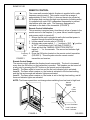
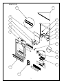
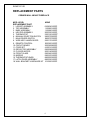
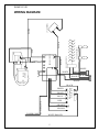
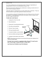
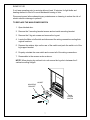
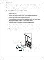
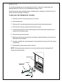
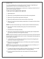
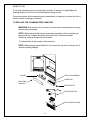
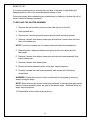
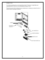
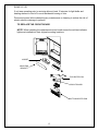
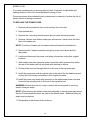
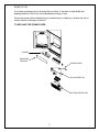
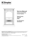
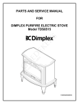
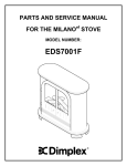
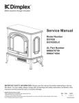
PARTS & SERVICE MANUAL
FOR THE CORNER WALL MOUNT
FIREPLACE
MODEL NUMBER:
EWMC-CC-SS
TABLE OF CONTENTS
OPERATION
PAGE 1
PARTS LIST DRAWING
PAGE 3
PARTS LIST
PAGE 4
WIRING DIAGRAM
PAGE 5
LIGHT BULB REPLACEMENT
PAGE 6
MAIN ON/OFF SWITCH REPLACEMENT
PAGE 7
MANUAL SELECTION SWITCH REPLACEMENT
PAGE 8
THERMOSTAT CONTROL REPLACEMENT
PAGE 9
FLAME MOTOR/FLAME ROD REPLACEMENT
PAGE 10
HEATER ASSEMBLY REPLACEMENT
PAGE 12
CIRCUIT BOARD REPLACEMENT
PAGE 14
POWER CORD REPLACEMENT
PAGE 16
MIRROR REPLACEMENT
PAGE 18
EWMC-CC-SS
OPERATION
MANUAL CONTROLS
The controls are located inside the door panel on the lower right hand side of the corner
wall mounted electric fireplace. (FIGURE 1)
A. MAIN POWER SWITCH
The MAIN on/off switch supplies power to the circuit
board. When the Main ON/OFF switch is switched to
the ON position the Level 1 indictor light will flash.
B
A
C
FIGURE 1
Manual
Selection
Switch
Main
Power
Switch
Level 3 Indicator
Level 2 Indicator
Level 1 Indicator
FIGURE 2
B. MANUAL SELECTION SWITCH
Pressing the left side of the switch “ — “ activates the
following functions:
1. Pressing once on the “MANUAL SELECTION
SWITCH” activates the Level 1 function.
Level 1: The flame effect is turned on and the first
red indicator light is activated.
2. Pressing twice on the “MANUAL SELECTION
SWITCH” activates the Level 2 function.
Level 2: The flame effect remains on, the heater is
activated to the low setting, and the first and
second red indicator lights are activated.
3. Pressing three times on the “MAIN SELECTION
SWITCH” activates the Level 3 function.
Level 3: The flame effect remains on, the heater is
set to the high heat setting, and all three red
indicator lights are activated.
Pressing the right side of the switch “ ═ “ once will
turn the unit OFF.
NOTE: The blower speed does not change when
switching from low heat to high heat.
C. HEATER THERMOSTAT CONTROL
To adjust the temperature to your individual
requirements, turn the thermostat control clockwise all
the way to turn on the heater. When the room
reaches the desired temperature, turn the thermostat
knob counter clockwise until you hear a click. Leave
in this position to maintain the room temperature at
this setting. For additional heat, turn clockwise until
you hear the click again and the heater will turn on.
RESETTING THE TEMPERATURE CUTOUT
SWITCH
Should the heater overheat, an automatic cut out will
turn the heater off and it will not come back on without
being reset. It can be reset by switching the MAIN
ON/OFF SWITCH to OFF and waiting 5 minutes
before switching the unit back on.
1
EWMC-CC-SS
REMOTE CONTROL
The corner wall mounted electric fireplace is supplied with a radio
frequency remote control. This remote control has a range of
approximately 50 feet (15.25m), it does not have to be pointed at
the fireplace and can pass through most obstacles (including walls).
It is supplied with one of 243 independent frequencies to prevent
interference with other units. The frequency designation is
indicated on the back of the transmitter (FIGURE 3).
Remote Control Initialization
This procedure is required every time there is a loss of power to the
remote control in the fireplace. (i.e. power failure, breaker tripped,
main power switch is turned off)
1. Ensure that the unit is plugged in wall outlet and that power is
supplied through the main service panel.
2. Locate manual controls refer to FIGURE 4.
3. Activate main power switch, (“ — ” position is “ON”, “ ” position
is “OFF”) red indicator light 1 will flash (FIGURE 5).
4. Press and hold the “MANUAL SELECTION SWITCH”
marked “ — “ for five seconds. The second red indicator light
will flash.
Frequency 5. Press the ON button located on the remote control transmitter
Code
(FIGURE 3). This will synchronize the remote control
FIGURE 3
transmitter and receiver.
Remote Control Usage
The remote control operates the fireplace levels sequentially. The level is increased
every time the ON button on the transmitter is pressed. The fireplace can be turned off
at any point by pressing the OFF button on the remote control transmitter.
Level 1: The flame effect is turned on and the first red indicator light is activated.
Level 2: The flame effect remains on, the heater is activated to the low heat setting,
and the first and second red indicator lights are activated.
Level 3: The flame effect remains on, the heater is set to the high heat setting, and all
three red indicator lights are activated.
NOTE: The blower speed does not change when switching from low heat to high heat.
Manual
Selection
Switch
Main
Power
Switch
B
Level 3 Indicator
A
Level 2 Indicator
Level 1 Indicator
C
FIGURE 4
2
FIGURE 5
EWMC-CC-SS
18
2
15
16
1
17
8
12
5
14
6
7
13
11
10
4
3
9
3
EWMC-CC-SS
REPLACEMENT PARTS
CORNER WALL MOUNT FIREPLACE
MOD. LEVEL
REPLACEMENT PART
1. LOGSET ASSEMBLY
2. TOP ASSEMBLY
3. BASE ASSEMBLY
4. HEATER ASSEMBLY
5. THERMOSTAT
6. MANUAL SELECTION SWITCH
7. MAIN POWER SWITCH
8. WIRE ASSY LAMPHOLDER
9. REMOTE CONTROL
10. CIRCUIT BOARD
11. CORD SET
12. REFLECTOR ASSEMBLY
13. FLICKER MOTOR
14. FRONT GLASS
15. MIRROR
16. THERMOSTAT KNOB
17. LATCH DOOR ASSEMBLY
18. WALL BRACKET HARDWARE KIT
NONE
0439040100RP
1106860183RP
1106890183RP
2000230100RP
2300150100RP*
2800070500RP
2800070700RP
2500170100RP
3000200100RP
3000200800RP
4100010100RP
5900080600RP
2000140300RP
5900460100RP
5900470100RP
8800000300RP
8800520100RP
1010950100RP
4
EWMC-CC-SS
WIRING DIAGRAM
THERMOSTAT
WHITE
FLICKER MOTOR
BLACK
N
WHITE
I
0
0
II
LEDs
YELLOW
I
ORANGE
MAIN SWITCH
HEATER SWITCH
BLUE
MARR
BLACK
MARR
RL1
5
AC120V
RL2
RED
WHITE ROUGH
WHITE SMOOTH
POWER CORD
CIRCUIT BOARD
RL3
BLACK
BLACK
BLACK
BLACK
BLACK
WHITE
WHITE
BLOWER
MOTOR
GREEN
LIGHT HARNESS
WHITE
RED
ELEMENT
BLACK
EWMC-CC-SS
If unit was operating prior to servicing allow at least 10 minutes for light bulbs and
heating element to cool off to avoid accidental burning of skin.
Disconnect power before attempting any maintenance or cleaning to reduce the risk of
electric shock or damage to persons.
Light bulbs need to be replaced when you notice a dark section of the flame. There are
two bulbs under the log set which generate the flames and embers.
It is a good idea to replace all of the light bulbs at one time if they are close to the end of
their rated life. Group replacement will reduce the number of times you need to open
the unit to replace the light bulbs.
TO REPLACE LIGHT BULBS
1. Unplug the unit from the outlet.
2. Open latched door.
3. Remove the 3 mounting bracket screws.
LOGSET
4. Set aside mounting bracket.
MOUNTING
BRACKET
5. Remove 2 log set screws.
6. Set log set assembly aside.
7. Unscrew the bulb(s) counter clockwise.
8. Insert new bulb(s) screwing clockwise.
9. Assemble in the reverse order as above.
NOTE: When placing log set back into unit ensure the log set sits in between the 2
vertical mounting flanges.
Quantity 2 clear chandelier or candelabra bulbs with an E-12 (small) socket
base, 60 watt rating. Example GE 60BC or Philips 60CTC
CAUTION DO NOT EXCEED 60 WATTS PER BULB
6
EWMC-CC-SS
If unit was operating prior to servicing allow at least 10 minutes for light bulbs and
heating element to cool off to avoid accidental burning of skin.
Disconnect power before attempting any maintenance or cleaning to reduce the risk of
electric shock or damage to persons.
TO REPLACE THE MAIN POWER SWITCH
1. Open latched door.
2. Remove the 3 mounting bracket screws and set aside mounting bracket.
3. Remove the 2 log set screws and remove the log set.
4. Locate the Main on/off switch and disconnect the wiring connections noting their
original locations.
5. Depress the retainer clips on the rear of the switch and push the switch out of the
log support bracket.
6. Properly orientate the new switch and connect all of the wiring connections.
7. Reassemble in the reverse order as above.
NOTE: When placing log set back into unit ensure the log sits in between the 2
vertical mounting flanges.
LOGSET
MOUNTING
BRACKET
MAIN
POWER
SWITCH
7
EWMC-CC-SS
If unit was operating prior to servicing allow at least 10 minutes for light bulbs and
heating element to cool off to avoid accidental burning of skin.
Disconnect power before attempting any maintenance or cleaning to reduce the risk of
electric shock or damage to persons.
TO REPLACE THE MANUAL SELECTION SWITCH
1. Open latched door.
2. Remove the 3 mounting bracket screws and set aside mounting bracket.
3. Remove the 2 log set screws and remove the log set.
4. Locate the manual selection switch and depress the retainer clips on the rear of
the switch and push the switch out of the log support bracket.
5. Disconnect the wiring connections noting their original locations.
6. Properly orientate the new switch and connect all of the wiring connections.
7. Reassemble in the reverse order as above.
NOTE: When placing log set back into unit ensure the log sits in between the 2
vertical mounting flanges.
LOGSET
MOUNTING
BRACKET
MANUAL
SELECTION
SWITCH
8
EWMC-CC-SS
If unit was operating prior to servicing allow at least 10 minutes for light bulbs and
heating element to cool off to avoid accidental burning of skin.
Disconnect power before attempting any maintenance or cleaning to reduce the risk of
electric shock or damage to persons.
TO REPLACE THE THERMOSTAT CONTROL
1. Remove unit from corner and lay unit on its side.
2. Open latched door.
3. Remove the 3 mounting bracket screws and set aside mounting bracket.
4. Remove the 2 log set screws and remove the log set.
5. Locate the thermostat control switch and pull off the thermostat control knob to
expose the mounting screws.
6. Remove the mounting screws.
7. Disconnect the wiring connections noting their original locations and remove the
thermostat control switch.
8. Properly orientate the new thermostat control switch and connect all of the wiring
connections.
9. Reassemble in the reverse order as above.
NOTE: When placing log set back into unit ensure the log sits in between the 2
vertical mounting flanges.
THERMOSTAT
LOGSET
MOUNTING
BRACKET
9
EWMC-CC-SS
If unit was operating prior to servicing allow at least 10 minutes for light bulbs and
heating element to cool off to avoid accidental burning of skin.
Disconnect power before attempting any maintenance or cleaning to reduce the risk of
electric shock or damage to persons.
TO REPLACE THE FLAME MOTOR/FLAME ROD
1. Open latched door.
2. Remove the 3 mounting bracket screws and set aside mounting bracket.
3. Remove the 2 log set screws and remove the log set.
4. Remove the wall mounted unit from corner and lay unit on its side.
5. Remove 4 screws from bottom heater pan and remove 2 screws from the front face
of the heater pan.
NOTE: Front face of bottom heater pan is located inside unit behind the latched door.
6. Disconnect the 3 heater assembly wires going to the circuit board and the
thermostat.
7. Set aside bottom heater pan assembly.
8. Remove the 4 screws along the inner edge of the top heater pan and separate the
top heater pan assembly from the light box assembly.
NOTE: It may be necessary to remove the cord wire from the main on/off switch and the
thermostat wire from the thermostat control in order to fully separate the heater pan top
from the light box assembly.
9. Locate the flame motor and flame rod assembly and remove the wiring clips and
connections noting their original locations.
10. Remove the 2 mounting bracket screws on the flame motor and pull the assembly
partially out of the light box.
NOTE: When removing the flame motor some damage may occur to the flame rod. If
flame rod is damaged replace to insure proper operation.
11. To remove the flame rod attach needle nose pliers to the spring on the motor shaft
and pull while rotating in the opposite direction of the spring winding.
12. Properly orientate the new flame motor and connect all of the wiring clips and
connections.
10
EWMC-CC-SS
If unit was operating prior to servicing allow at least 10 minutes for light bulbs and
heating element to cool off to avoid accidental burning of skin.
Disconnect power before attempting any maintenance or cleaning to reduce the risk of
electric shock or damage to persons.
TO REPLACE THE FLAME MOTOR/FLAME ROD
WARNING: Ensure wires do not come in contact with moving parts by securing
wires in wiring tie wraps.
NOTE: When securing the bottom heater pan assembly to the top heater pan
ensure that the 3 heater assembly wires are clear of the blower wheel.
Additional wiring tie wraps may be required.
13. Reassemble in the reverse order as above.
NOTE: When placing log set back into unit ensure the log sits in between the 2
vertical mounting flanges.
LOGSET
LIGHT BOX ASSEMBLY
FLAME ROD
MOUNTING
BRACKET
FLAME MOTOR
TOP HEATER PAN
BOTTOM HEATER PAN
11
EWMC-CC-SS
If unit was operating prior to servicing allow at least 10 minutes for light bulbs and
heating element to cool off to avoid accidental burning of skin.
Disconnect power before attempting any maintenance or cleaning to reduce the risk of
electric shock or damage to persons.
TO REPLACE THE HEATER ASSEMBLY
1. Remove the wall mounted unit from corner and lay unit on its side.
2. Open latched door.
3. Remove the 3 mounting bracket screws and set aside mounting bracket.
4. Remove 4 screws from bottom heater pan and remove 2 screws from the front
face of the heater pan.
NOTE: Front face of heater pan is located inside unit behind the latched door.
5. Disconnect the 3 heater assembly wires going to the circuit board and the
thermostat.
6. Remove 4 screws from bottom heater pan and remove heater assembly from
bottom heater pan.
7. Remove 4 screws from heater plate.
8. Disconnect heater assembly wires noting their original locations.
9. Properly orientate the new heater assembly and connect all of the wiring
connections.
WARNING: Ensure wires do not come in contact with moving parts by securing
wires in wiring tie wraps.
NOTE: When securing the bottom heater pan assembly to the top heater pan ensure
that the 3 heater assembly wires are clear of the blower wheel. Additional wiring tie
wraps may be required.
10. Reassemble in the reverse order as above.
12
EWMC-CC-SS
If unit was operating prior to servicing allow at least 10 minutes for light bulbs and
heating element to cool off to avoid accidental burning of skin.
Disconnect power before attempting any maintenance or cleaning to reduce the risk of
electric shock or damage to persons.
LOGSET
MOUNTING
BRACKET
TOP HEATER PAN
HEATER ASSEMBLY
HEATER PLATE
BOTTOM HEATER PAN
13
EWMC-CC-SS
If unit was operating prior to servicing allow at least 10 minutes for light bulbs and
heating element to cool off to avoid accidental burning of skin.
Disconnect power before attempting any maintenance or cleaning to reduce the risk of
electric shock or damage to persons.
TO REPLACE THE CIRCUIT BOARD
1. Remove wall mounted unit from corner and lay unit on its side.
2. Open latched door.
3. Remove the 3 mounting bracket screws and set aside mounting bracket.
4. Remove 4 screws from bottom heater pan and remove 2 screws from the front
face of the heater pan.
NOTE: Front face of heater pan is located inside unit behind the latched door.
5. Disconnect the 3 heater assembly wires going to the circuit board and the
thermostat.
6. Remove the red indicator lights out through the bottom of the log support bracket
noting their original locations.
7. Locate the manual selection switch and depress the retainer clips on the rear of
the switch and push the switch out of the log support bracket.
8. Disconnect the wiring connections noting their original locations.
9. Locate the remote control circuit board mounted to the back of the top heater pan
and remove the wiring connections noting their original locations.
10. Depress the ends of the four plastic mounting posts with pliers.
11. Remove the circuit board from unit.
12. Properly orientate the replacement circuit board and connect all of the wiring
connections.
WARNING: Ensure wires do not come in contact with moving parts by securing
wires in wiring tie wraps.
NOTE: When securing the bottom heater pan assembly to the top heater pan ensure
that the 3 heater assembly wires are clear of the blower wheel. Additional wiring tie
wraps may be required.
13. Reassemble in the reverse order as above.
14
EWMC-CC-SS
If unit was operating prior to servicing allow at least 10 minutes for light bulbs and
heating element to cool off to avoid accidental burning of skin.
Disconnect power before attempting any maintenance or cleaning to reduce the risk of
electric shock or damage to persons.
TO REPLACE THE CIRCUIT BOARD
NOTE: When installing the replacement circuit board ensure the red heat indicator
lights are installed into their original mounting locations.
LOGSET
MOUNTING
BRACKET
TOP HEATER PAN
CIRCUIT BOARD
BOTTOM HEATER PAN
15
EWMC-CC-SS
If unit was operating prior to servicing allow at least 10 minutes for light bulbs and
heating element to cool off to avoid accidental burning of skin.
Disconnect power before attempting any maintenance or cleaning to reduce the risk of
electric shock or damage to persons.
TO REPLACE THE POWER CORD
1. Remove wall mounted unit from corner and lay unit on its side.
2. Open latched door.
3. Remove the 3 mounting bracket screws and set aside mounting bracket.
4. Remove 4 screws from bottom heater pan and remove 2 screws from the front
face of the heater pan.
NOTE: Front face of heater pan is located inside unit behind the latched door.
5. Disconnect the 3 heater assembly wires going to the circuit board and the
thermostat.
6. Locate and disconnect the power cord wiring connections noting their original
locations.
7. With needle nose pliers grasp the power cord strain relief grommet from inside
the rear of the heater pan top and push while twisting to remove.
8. Pull the power cord out through the hole in the rear of the top heater pan.
9. Install the new power cord through the hole in the rear of the top heater pan and
connect all of the wiring connections in their original locations.
10. Install the power cord strain relief grommet on the replacement power cord and
insert into the mounting hole in the rear of the top heater pan.
WARNING: Ensure wires do not come in contact with moving parts by securing
wires in wiring tie wraps.
NOTE: When securing the bottom heater pan assembly to the top heater pan ensure
that the 3 heater assembly wires are clear of the blower wheel. Additional wiring tie
wraps may be required.
11. Reassemble in the reverse order as above.
16
EWMC-CC-SS
If unit was operating prior to servicing allow at least 10 minutes for light bulbs and
heating element to cool off to avoid accidental burning of skin.
Disconnect power before attempting any maintenance or cleaning to reduce the risk of
electric shock or damage to persons.
TO REPLACE THE POWER CORD
LOGSET
MOUNTING
BRACKET
POWER CORD
TOP HEATER PAN
BOTTOM HEATER PAN
17
EWMC-CC-SS
If unit was operating prior to servicing allow at least 10 minutes for light bulbs and
heating element to cool off to avoid accidental burning of skin.
Disconnect power before attempting any maintenance or cleaning to reduce the risk of
electric shock or damage to persons.
TO REPLACE THE MIRROR
1. Remove wall mounted unit from corner and lay unit on its side.
2. Open latched door.
3. Remove door chain bolt and nut from back panel assembly.
4. Remove top mirror bracket from back panel and set aside.
5. Remove mirror from unit and remove black rubber channels from mirror.
6. Install black rubber channels to replacement mirror.
7. Reassemble in the reverse order as above.
18