1
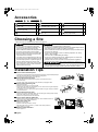
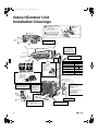
00_CV_3P147083-2F.fm Page 1 Wednesday, September 28, 2005 10:34 AM INSTALLATION MANUAL R410A Split Series Installation manual R410A Split series Models FTYN25DV3B FTYN35DV3B FTYN25DAV3B FTYN35DAV3B FTN25DV3B FTN35DV3B FTN25DAV3B FTN35DAV3B English Installationsanleitung Split-Baureihe R410A Deutsch Manuel d’installation Série split R410A Français Montagehandleiding R410A Split-systeem Manual de instalación Serie Split R410A Manuale d’installazione Serie Multiambienti R410A Εγχειρßδιο εγκατÜστασηò διαιροýìενηò σειρÜò R410A Manual de Instalação Série split R410A Рóêоводство по монтажó Серия R410A с раздельной óстановêой Montaj kýlavuzlarý R410A Split serisi Nederlands Español Italiano ΕλληνικÜ Portugues Рóссêий Türkçe Daikin.TCF.020 95951-KRQ/ECMC99-4476. Daikin.TCF.020 95951-KRQ/ECMC99-4476. Daikin.TCF.020 95951-KRQ/ECMC99-4476. Daikin.TCF.020 95951-KRQ/ECMC99-4476. Daikin.TCF.020 95951-KRQ/ECMC99-4476. Daikin.TCF.020 95951-KRQ/ECMC99-4476. Daikin.TCF.020 95951-KRQ/ECMC99-4476. Daikin.TCF.020 95951-KRQ/ECMC99-4476. Daikin.TCF.020 95951-KRQ/ECMC99-4476. Noboru Murata Manager Quality Control Department Shiga, 1st of Nov. 2005 Daikin.TCF.020 95951-KRQ/ECMC99-4476 Daikin.TCF.020 95951-KRQ/ECMC99-4476. Daikin.TCF.020 95951-KRQ/ECMC99-4476. Daikin.TCF.020 95951-KRQ/ECMC99-4476 Daikin.TCF.020 95951-KRQ/ECMC99-4476. Daikin.TCF.020 95951-KRQ/ECMC99-4476. 95951-KRQ/ECMC99-4476. Daikin.TCF.020 Daikin.TCF.020 Daikin.TCF.020 95951-KRQ/ECMC99-4476. 95951-KRQ/ECMC99-4476. FTYN25DV3B, FTYN35DV3B, FTYN25DAV3B, FTYN35DAV3B, FTN25DV3B, FTN35DV3B, FTN25DAV3B, FTN35DAV3B, RYN25DV3B, RYN35DV3B, RYN25DAV3B, RYN35DAV3B, RN25DV3B, RN35DV3B, RN25DAV3B, RN35DAV3B DAIKIN INDUSTRIES, LTD. 2SB63475-6C Daikin.TCF.020 Daikin.TCF.020 95951-KRQ/ECMC99-4476. Umeda Center Bldg., 4-12, Nakazaki-Nishi 2-chome, Kita-ku, Osaka, 530-8323 Japan Daikin.TCF.020 95951-KRQ/ECMC99-4476. Daikin.TCF.020, 95951-KRQ/ECMC99-4476. Daikin.TCF.020 95951-KRQ/ECMC99-4476. Daikin.TCF.020 95951-KRQ/ECMC99-4476 95951-KRQ/ECMC99-4476. 95951-KRQ/ECMC99-4476. Daikin.TCF.020 01_EN_3P147083-2F.fm Page 1 Friday, October 28, 2005 9:29 AM Safety Precautions • Read these Safety Precautions carefully to ensure correct installation. • This manual classifies the precautions into WARNING and CAUTION. Be sure to follow all the precautions below: they are all important for ensuring safety. WARNING...............Failure to follow any of WARNING is likely to result in such grave consequences as death or serious injury. CAUTION...............Failure to follow any of CAUTION may in some cases result in grave consequences. • The following safety symbols are used throughout this manual: Be sure to observe this instruction. Be sure to establish an earth connection. Never attempt. • After completing installation, test the unit to check for installation errors. Give the user adequate instructions concerning the use and cleaning of the unit according to the Operation Manual. WARNING • Installation should be left to the dealer or another professional. Improper installation may cause water leakage, electrical shock, or fire. • Install the air conditioner according to the instructions given in this manual. Incomplete installation may cause water leakage, electrical shock, or fire. • Be sure to use the supplied or specified installation parts. Use of other parts may cause the unit to come to lose, water leakage, electrical shock, or fire. • Install the air conditioner on a solid base that can support the unit’s weight. An inadequate base or incomplete installation may cause injury in the event the unit falls off the base. • Electrical work should be carried out in accordance with the installation manual and the national electrical wiring rules or code of practice. Insufficient capacity or incomplete electrical work may cause electrical shock or fire. • Be sure to use a dedicated power circuit. Never use a power supply shared by another appliance. • For wiring, use a cable long enough to cover the entire distance with no connection. Do not use an extension cord. Do not put other loads on the power supply, use a dedicated power circuit. (Failure to do so may cause abnormal heat, electric shock or fire.) • Use the specified types of wires for electrical connections between the indoor and outdoor units. Firmly clamp the interconnecting wires so their terminals receive no external stresses. Incomplete connections or clamping may cause terminal overheating or fire. • After connecting interconnecting and supply wiring be sure to shape the cables so that they do not put undue force on the electrical covers or panels. Install covers over the wires. Incomplete cover installation may cause terminal overheating, electrical shock, or fire. • If any refrigerant has leaked out during the installation work, ventilate the room. (The refrigerant produces a toxic gas if exposed to flames.) • After all installation is complete, check to make sure that no refrigerant is leaking out. (The refrigerant produces a toxic gas if exposed to flames.) • When installing or relocating the system, be sure to keep the refrigerant circuit free from substances other than the specified refrigerant (R410A), such as air. (Any presence of air or other foreign substance in the refrigerant circuit causes an abnormal pressure rise or rupture, resulting in injury.) • During pump-down, stop the compressor before removing the refrigerant piping. If the compressor is still running and the shut-off valve is open during pump-down, air will be sucked in when the refrigerant piping is removed, causing abnormal pressure in the freezer cycle which will lead to breakage and even injury. • During installation, attach the refrigerant piping securely before running the compressor. If the compressor is not attached and the shut-off valve is open during pump-down, air will be sucked in when the compressor is run, causing abnormal pressure in the freezer cycle which will lead to breakage and even injury. • Be sure to establish an earth. Do not earth the unit to a utility pipe, arrester, or telephone earth. Incomplete earth may cause electrical shock, or fire. A high surge current from lightning or other sources may cause damage to the air conditioner. • Be sure to install an earth leakage breaker. Failure to install an earth leakage breaker may result in electric shocks, or fire. CAUTION • Do not install the air conditioner in a place where there is danger of exposure to inflammable gas leakage. If the gas leaks and builds up around the unit, it may catch fire. • Establish drain piping according to the instructions of this manual. Inadequate piping may cause flooding. • Note for installing the outdoor unit. (For heat pump model only.) In cold area where the outside air temperature keep below or around freezing-point for a few days, the outdoor unit’s drain may freeze. If so, it is recommended to install an electric heater in order to protect drain from freezing. • Tighten the flare nut according to the specified method such as with a torque wrench. If the flare nut is tightened too hard, the flare nut may crack after a long time and cause refrigerant leakage. • Make sure to provide for adequate measures in order to prevent that the outdoor unit be used as a shelter by small animals. Small animals making contact with electrical parts can cause malfunctions, smoke or fire. Please instruct the customer to keep the area around the unit clean. 1 ■English 01_EN_3P147083-2F.fm Page 2 Friday, October 28, 2005 9:29 AM Accessories Indoor unit A – L , Outdoor unit M A Mounting plate 1 E Remote controller holder 1 J Thermistor cable (8m)*1 1 B Mounting plate fixing screw M4 × 25L 6 F Fixing screw for remote controller holder M3 × 20L 2 K Operation manual 1 C Titanium Apatite Photocatalytic Air-Purifying Filter 2 G AAA dry-cell batteries 2 L Installation manual 1 D Wireless remote controller 1 H Indoor unit fixing screw M4 × 12L 2 M Drain plug (Heat pump-Models) 1 *1 The thermistor cable is attached to the indoor unit. Choosing a Site • Before choosing the installation site, obtain user approval. Indoor unit The indoor unit should be sited in a place where: • the restrictions on installation specified in the indoor unit installation drawings are met, • both air intake and exhaust have clear paths met, • the unit is not in the path of direct sunlight, • the unit is away from the source of heat or steam, • there is no source of machine oil vapour (this may shorten indoor unit life), • cool (heat) air is circulated throughout the room, • the unit is away from electronic ignition type fluorescent lamps (inverter or rapid start type) as they may shorten the remote control range, • the unit is at least 1 metre away from any television or radio set (unit may cause interference with the picture or sound). Outdoor unit The outdoor unit should be sited in a place where: • the restrictions on installation specified in the outdoor unit installation diagram are met, • drain water causes no trouble or problem in particular, • both air intake and exhaust have clear paths of air (they should be free of snow in snowy districts), • the unit is in a clear path of air but not directly exposed to rain, strong winds, or direct sunlight, • there is no fear of inflammable gas leakage, • the unit is no directly exposed to salt, sulfidized gases, or machine oil vapour (they may shorten outdoor unit life), • operation noise or hot air flow does not cause trouble to neighbours, • the unit is at least 3 metres away from any television or radio antenna. Wireless remote controller • Turn on all the fluorescent lamps in the room, if any, and find the site where remote controller signals are properly received by the indoor unit (within 7 metres). Installation Tips ■ How to remove the front panel. • Hook fingers on the panel protrusions on the left and right of the main body, and open until the panel stops. • Slide the front panel sideways to disengage the rotating shaft. • Then pull the front panel toward you to remove it. ■ How to attach the front panel. • Align the tabs of the front panel with the grooves, and push all the way in. • Then close slowly. • Push the center of the lower surface of the panel firmly to engage the tabs. Fit the key into the slot. ■ How to remove the front grille. • Open the front panel. • Remove the screws (2 pcs) on the front grille. • Pull the lower part of the front grille toward you, then remove the front grille completely. Upper hook Raise and remove Upper grille Hook Screwdriver (There are 2 hooks on the upper part.) If it is difficult to remove, open the front grille and raise the top grid, using a screwdriver, to unhook the hooks. Screwdriver ■ How to attach the front grille. Filter guide • Attach the front grille to the bottom frame, and lock the upper hooks (2points) securely. • Tighten the screws (2 pcs) on the front grille. • Attach the front panel and close the front panel. ■ How to set the different addresses. Claws (4 point) • When two indoor units are installed in one room, the two wireless remote controllers can be set for different addresses. Metallic cover J4 ADDRESS JA JC J30 Electric parts box C1 ■ Wireless remote controller. C31 • Remove the front panel. • Remove the electric parts box (1-screw). • Slide the metalic cover to remove it. (4-claws on the electric parts box) • Cut the jumper JA on PCB. JP11 ■ PCB in the indoor unit. J4 ADDRESS EXIST 1 CUT 2 Wireless remote controller ADDRESS: JA EXIST 1 CUT 2 PCB • Cut the jumper J4. ■English 2 01_EN_3P147083-2F.fm Page 3 Friday, October 28, 2005 9:29 AM Indoor/Outdoor Unit Installation Drawings How to attach the indoor unit. Hook the claws of the bottom frame to the mounting plate. If the claws are difficult to hook, remove the front grille. A Mounting plate Clip How to remove the indoor unit. Push up the marked area (at the lower part of the front grille) to release the claws. If it is difficult to Front grille release, remove the front grille. A Mounting plate B M4 × 25L Bottom frame Mark (rear side) The mounting plate should be installed on a wall which can support the weight of the indoor unit. Cut thermal insulation pipe to an appropriate length and wrap it with tape, making sure that no gap is left in the insulation pipe’s cut line. 30mm or more from ceiling Front panel 50mm or more from walls (on both sides) Wrap the insulation pipe with the finishing tape from bottom to top. Caulk pipe hole gap with putty. Air filter Model Service lid This service lid is an open/close type. Remove the screws on the service lid. Slide the service lid leftward. Rotate the service lid upward. 15m Max. allowable length Max. allowable length without additional charge Max. allowable height 35 3m 20g/m Additional charge of refrigerant C Titanim Apatite Photocatalytic Air-Purifying Filter (2) 7.5m 10m 10m Gas pipe O.D. 9.5mm Liquid pipe O.D. 6.4mm * Be sure to add the proper amount of additional refrigerant. Air filter Titanium Apatite Photocatalytic Air-Purifying Filter 25 Min. allowable length Failure to do so may result in reduced perfomance. Filter frame J Thermistor cable Use optional kit when extending the thermistor cable. Tab Before screwing the remote controller holder to the wall, make sure that control signals are properly received by indoor unit. Push D Wireless remote controller Set F M3 × 20L 3 If there is a lot of vibration with outdoor unit installations such as wall-mounted installations, use antivibration rubber, etc., for the outdoor unit. E Remote controller holder Service lid How to remove the service lid. Remove the screw on the service lid. Slide the lid downward to remove it. 250mm from wa ll How to attach the service lid. Insert the upper part of the service lid into the outdoor unit to install. Tighten the screws. 8 hole 28 boltot ) (Fo ntres ce 470 olt-hole centre s (Foot b In sites with poor drainage, use block bases for outdoor unit. Adjust foot height until the unit is leveled. Otherwise, water leakage or pooling of water may occur. ) 115 (From unit’s Allow space for piping and electrical servicing. side) Where there is a danger of the unit falling, use foot bolts, or wires. unit: mm ■English 01_EN_3P147083-2F.fm Page 4 Friday, October 28, 2005 9:29 AM Outdoor Unit Installation Guidelines • Where a wall or other obstacle is in the path of outdoor unit’s intake or exhaust airflow, follow the installation guidelines below. Wall facing one side More than 50 Walls facing two sides More than 100 More than 100 More than 150 More than 50 More than 50 Top view Side view Walls facing three sides More than 150 More than 300 More than 50 Top view Unit: mm CAUTION When operating the air conditioner in a low outdoor ambient temperature, be sure to follow the instructions described below. 1) To prevent exposure to wind, install the outdoor unit with its suction side facing the wall. 2) Never install the outdoor unit at a site where the suction side may be exposed directly to wind. 3) To prevent exposure to wind, it is recommended to install a baffle plate on the air discharge side of the outdoor unit. 4) In heavy snowfall areas, select an installation site where the snow will not affect the unit. ■English Construct a large canopy. Construct a pedestal. Install the unit high enough off the ground to prevent burying in snow. 4 01_EN_3P147083-2F.fm Page 5 Friday, October 28, 2005 9:29 AM Indoor Unit 1. Installing the mounting plate. • The mounting plate should be installed on a wall which can support the weight of the indoor unit. 1) Temporarily secure the mounting plate to the wall, make sure that the panel is completely level, and mark the boring points on the wall. 2) Secure the mounting plate to the wall with screws. Recommended mounting plate retention spots and Dimensions Leveling mounting plate a (Bolt size : M10) Recommended mounting plate retention spots (6 spots in all) 105 Use tape measure as shown. Dangle a weighted thread and align thread with vertical arrow. Place a leveler b on raised tab. Position the end of tape measure at ∇. 95 60 65 269 Gas pipe end 50 Unit outline 110 85 41.5 41.5 85 273 52 51 (Bolt size : M10) Liquid pipe end 734 Through-the-wall hole ø65mm (unit: mm) Drain hose position * The removed pipe port cover can be kept in the mounting plate pocket Removed pipe port cover A Mounting plate 2. Boring a wall hole and installing wall embedded pipe. • For walls containing metal frame or metal board, be sure to use a wall embedded pipe and wall cover in the feed-through hole to prevent possible heat, electrical shock, or fire. • Be sure to caulk the gaps around the pipes with caulking material to prevent water leakage. 1) Bore a feed-through hole of 65mm in the wall so it has a down slope toward the outside. 2) Insert a wall pipe into the hole. 3) Insert a wall cover into wall pipe. 4) After completing refrigerant piping, wiring, and drain piping, caulk pipe hole gap with putty. 5 Inside Wall embedded pipe (Field supply) Outside Caulking φ65 Wall hole cover (Field supply) Wall embedded pipe (Field supply) ■English 01_EN_3P147083-2F.fm Page 6 Friday, October 28, 2005 9:29 AM 3. Installing indoor unit. 3-1. Right-side, right-back, or right-bottom piping. 1) Attach the drain hose to the underside of the refrigerant pipes with adhesive vinyl tape. 2) Wrap the refrigerant pipes and drain hose together with insulation tape. Right-back piping Remove pipe port cover here for right-side piping Right-bottom piping Bind coolant pipe Remove pipe port cover here for right-bottom piping 3) Pass the drain hose and refrigerant pipes through the wall hole, then set the indoor unit on the mounting plate hooks by using the markings at the top of the indoor unit as a guide. 4) Open the front panel, then open the service lid. (Refer to Installation Tips) 5) Pass the interconnecting wires from the outdoor unit through the feed-through wall hole and then through the back of the indoor unit. Pull them through the front side. Bend the ends of tie wires upward in advance for easier work. (If the interconnecting wire ends are to be stripped first, bundle wire ends with adhesive tape.) 6) Press the indoor unit’s bottom panel with both hands to set it on the mounting plate hooks. Make sure the wires do not catch on the edge of the indoor unit. and drain hose together with insulating tape. A Mounting plate Hang indoor unit’s hook here. A Mounting plate When stripping the ends of interconnecting wires in advance, bind right ends of wires with insulating tape. Interconnecting wires Wire guide 3-2. Left-side, left-back, or left-bottom piping. Remove pipe 1) Attach the drain hose to the underside of the refrigerant pipes with adhesive vinyl tape. port cover here for leftside piping Left-side piping Remove pipe port cover here for left-bottom piping Left-back piping Left-bottom piping 2) Be sure to connect the drain hose to the drain port in place of a drain plug. How to set drain plug ap No g Do not apply lubricating oil (refrigerant machine oil) when inserting. Application of causes deterioration and drain leakage of the plug. Insert a hexagon wrench (4mm) 3) Shape the refrigerant pipe along the pipe path marking on the mounting plate. 4) Pass drain hose and refrigerant pipes through the wall hole, then set the indoor unit on mounting plate hooks, using the markings at the top of indoor unit as a guide. 5) Pull in the interconnecting wires. 6) Connect the inter-unit piping. ■English Drain hose A Mounting plate Caulk this hole with putty or caulking material. Wrap insulating tape around the bent portion of refrigerant pipe. Overlap at least half the width of the tape with each turn. Interconnecting wires Bind with plastic tape. Thermistor cable 6 01_EN_3P147083-2F.fm Page 7 Friday, October 28, 2005 9:29 AM Indoor Unit Note: 1) Wrap the refrigerant pipes and drain hose together with insulation tape as right figure, in case of setting the drain hose through the back of the indoor unit. 2) If it difficult to fix the claws of the bottom frame on the catches of the mounting plate. Secure indoor unit to the mounting plate with scres (M4 × 12L). Drain hose A Mounting plate Refrigerant pipes Bottom frame 3-3. Wall embedded piping. H M4 × 12L (2 point) Follow the instructions given under Insert drain hose Left-side, left-back, or left-bottom piping . 1) Insert the drain hose to this depth so it wont be pulled out of the drain pipe. 4. to this depth so Inner wall it wont be pulled out of drain pipe. 50mm Drain hose or more Wiring. Vinyl chloride drain pipe Outer wall (VP-30) WARNING 1) Do not use tapped wires, stand wires, extensioncords, or starbust connections, as they may cause overtheating, electrical shock,or fire. 2) Do not use locally purchased electrical parts inside the product. (Do not branch the power for the drain pump, etc., from the terminal block.) Doing so may cause electric shock or fire. 3) Be sure to install an earth leak detector. (Failure to install an earth leakage breaker may result in electric shocks.) 4) When wiring indoor and outdoor units, always connect terminals together having the same numbers. Should any terminal be connected to another terminal that has a different number, the air conditioner may stop running, or the fuse on the indoor or outdoor unit may blow out. (See the electric wiring diagram included with the product for details on the fuse specifications.) • Do not turn ON the safety breaker until all work is completed. 1) Strip wire ends (15mm). 2) Match wire colours with terminal numbers on indoor and outdoor units’ terminal blocks and firmly screw wires to the corresponding terminals. 3) Connect the earth wires to the corresponding terminals. 4) Pull wires to make sure that they are securely latched up, then retain wires with wire retainer. 5) Shape the wires so that the service lid fits securely, then close service lid. <FTYN> Terminal block 1 2 3 4 5 Electrical component box Wire retainer Shape wires so that the service lid will fit securely. Firmly secure wire retainer so that wires sustain no external stress. Use the specified wire type. Firmly fix the wires with the terminal screws. When wire length exceeds 10m, use 2.0mm wires. Outdoor unit 12 345 LN The earth leakage circuit breaker is required depending on site environment. 5 Safety breaker 16A Indoor 43 unit 2 1 Firmly fix the wires with the terminal screws. Earth leakage circuit breaker Power supply 50Hz 230V H05VV Earth Thermistor cable (Included with the indoor unit) 7 ■English 01_EN_3P147083-2F.fm Page 8 Friday, October 28, 2005 9:29 AM <FTN> Terminal block 1 2 3 4 Electrical component box Wire retainer Shape wires so that the service lid will fit securely. Firmly secure wire retainer so that wires sustain no external stress. Use the specified wire type. Firmly fix the wires with the terminal screws. When wire length exceeds 10m, use 2.0mm wires. Outdoor unit 12 34 LN The earth leakage circuit breaker is required depending on site environment. Safety breaker 16A Indoor 43 unit 2 1 Firmly fix the wires with the terminal screws. Earth leakage circuit breaker Power supply 50Hz 230V H05VV Earth Thermistor cable (Included with the indoor unit) 5. Thermistor cable. The thermistor cable is secured to the indoor unit. If performing the wiring after removing the thermistor cable, follow the procedure outlined below. Removing the Thermistor Cable 1) Remove the front grille. (Refer to the Installation Tips.) 2) Remove the connector. 3) Remove the screw (1 pcs) securing the cable fixture and then remove the thermistor cable. Thermistor cable Attaching the Thermistor Cable 1) Secure the thermistor cable using the cable fixture. (1 screw) 2) Connect the connector after the thermistor cable has been secured. 6. Cable fixture Binding band Drain piping. The drain hose should be inclined downward. 1) Connect the drain hose, as described right. No trap is permitted. Do not put the end of the hose in water. 3) When drain hose requires extension, obtain an extension hose commercially available. Be sure to thermally insulate the indoor section of the extension hose. Indoor unit drain hose φ18 2) Remove the air filters and pour some water into the drain pan to check the water flows smoothly. Extension drain hose 4) When connecting a rigid polyvinyl chloride pipe (nominal diameter 13mm) directly to the drain hose attached to the indoor unit as with embedded piping work, use any commercially available drain socket (nominal diameter 13mm) as a joint. ■English φ18 Heat insulation tube (Field supply) Drain hose supplied with Commercially available drain Commercially available rigid the indoor unit socket polyvinyl chloride pipe (nominal diameter 13mm) (nominal diameter 13mm) 8 01_EN_3P147083-2F.fm Page 9 Friday, October 28, 2005 9:29 AM Outdoor Unit 1. Installing outdoor unit. • For outdoor unit installation, see Choosing a Site Outdoor unit 2. and Indoor/Outdoor Unit Installation Drawings. Flaring the pipe end. 1) Cut the pipe end with a pipe cutter. 2) Remove burrs with the cut surface facing downward so that the chips do not enter the pipe. 3) Put the flare nut on the pipe. 4) Flare the pipe. 5) Check that the flaring is properly made. (Cut exactly at right angles.) Remove burrs Flaring Set exactly at the position shown below. A Die Flare tool for R410A Conventional flare tool Clutch-type Clutch-type (Rigid-type) Wing-nut type (Imperial-type) A 0-0.5mm 1.0-1.5mm 1.5-2.0mm Check Flare’s inner surface must be flaw-free. The pipe end must be evenly flared in a perfect circle. Make sure that the flare nut is fitted. WARNING 1) 2) 3) 4) 5) 6) 3. Do not use mineral oil on flared part. Prevent mineral oil from getting into the system as this would reduce the lifetime of the units. Never use piping which has been used for previous installations. Only use parts which are delivered with the unit. Do never install a drier to this R410A unit in order to guarantee its lifetime. The drying material may dissolve and damage the system. Incomplete flaring may cause refrigerant gas leakage. Refrigerant piping. Flare nut tightening torque Gas side Liquid side 3/8 inch 1/4 inch 32.7-39.9N l m 14.2-17.2N l m (333-407kgf l cm) (144-175kgf l cm) 1) Align the centres of both flares and tighten the flare nuts 3 or 4 turns by hand. Then tighten them fully with the torque wrenches. • Use torque wrenches when tightening the flare nuts to prevent damage to the flare nuts and escaping gas. 2) To prevent gas leakage, apply refrigeration machine oil on both inner and outer surfaces of the flare. (Use refrigeration oil for R410A) Valve cap tightening torque Gas side Liquid side 3/8 inch 1/4 inch 21.6-27.4N l m 21.6-27.4N l m (220-280kgf l cm) (220-280kgf l cm) 10.8-14.7N l m (110-150kgf l cm) Service port cap tightening torque 3-1. Caution on piping handling. 1) Protect the open end of the pipe against dust and moisture. 2) All pipe bends should be as gentle as possible. Use a pipe bender for bending. (Bending radius should be 30 to 40mm or larger.) Wall Be sure to place a cap. Rain If no flare cap is available, cover the flare mouth with tape to keep dirt or water out. 3-2. Selection of copper and heat insulation materials. • When using commercial copper pipes and fittings, observe the following: 1) Insulation material: Polyethylene foam Heat transfer rate: 0.041 to 0.052W/mK (0.035 to 0.045kcal/mh°C) Refrigerant gas pipe’s surface temperature reaches 110°C max. Choose heat insulation materials that will withstand this temperature. 2) Be sure to insulate both the gas and liquid piping and to provide insulation dimensions as below. Gas side Liquid side 25/35 class O.D. 9.5mm Gas pipe thermal insulation 25/35 class O.D. 6.4mm Thickness 0.8mm I.D. 12-15mm Inter-unit wiring Gas pipe Liquid pipe Gas pipe Liquid pipe insulation Liquid pipe thermal insulation Thermistor cable insulation Finishing tape Drain hose I.D. 8-10mm Thickness 10mm Min. 3) Use separate thermal insulation pipes for gas and liquid refrigerant pipes. 9 ■English 01_EN_3P147083-2F.fm Page 10 Friday, October 28, 2005 9:29 AM 4. Purging air and checking gas leakage. • When piping work is completed, it is necessary to purge the air and check for gas leakage. WARNING 1) 2) 3) 4) Do not mix any substance other than the specified refrigerant (R410A) into the refrigeration cycle. When refrigerant gas leaks occur, ventilate the room as soon and as much as possible. R410A, as well as other refrigerants, should always be recovered and never be released directly into the environment. Use a vacuum pump for R410A exclusively. Using the same vacuum pump for different refrigerants may damage the vacuum pump or the unit. • If using additional refrigerant, perform air purging from the refrigerant pipes and indoor unit using a vacuum pump, then charge additional refrigerant. • Use a hexagonal wrench (4mm) to operate the shut-off valve rod. • All refrigerant pipe joints should be tightened with a torque wrench at the specified tightening torque. Pressure Compound meter pressure gauge Gauge manifold Valve lids HighLow-pressure pressure valve valve Charging Liquid hoses Service port Gas shut-off Vacuum pump shut-off valve valve 1) Connect projection side (on which worm pin is pressed) of charging hose (which comes from gauge manifold) to gas shut-off valve’s service port. 2) Fully open gauge manifold’s low-pressure valve (Lo) and completely close its high-pressure valve (Hi). (High-pressure valve subsequently requires no operation.) 3) Do vacuum pumping and make sure that the compound pressure gauge reads –0.1MPa (–76cmHg)*1. 4) Close gauge manifold’s low-pressure valve (Lo) and stop vacuum pump. (Keep this state for a few minutes to make sure that the compound pressure gauge pointer does not swing back.)*2. 5) Remove covers from liquid shut-off value and gas shut-off valve. 6) Turn the liquid shut-off valve’s rod 90 degrees counterclockwise with a hexagonal wrench to open valve. Close it after 5 seconds, and check for gas leakage. Using soapy water, check for gas leakage from indoor unit’s flare and outdoor unit’s flare and valve rods. After the check is complete, wipe all soapy water off. 7) Disconnect charging hose from gas shut-off valve’s service port, then fully open liquid and gas shut-off valves. (Do not attempt to turn valve rod beyond its stop.) 8) Tighten valve lids and service port caps for the liquid and gas shut-off valves with a torque wrench at the specified torques. *1. Pipe length vs. vacuum pump run time Pipe length Up to 15 metres More than 15 metres Run time Not less than 10 min. Not less than 15 min. *2. If the compound pressure gauge pointer swings back, refrigerant may have water content or a loose pipe joint may exists. Check all pipe joints and retighten nuts as needed, then repeat steps 2) through 4). ■English 10 01_EN_3P147083-2F.fm Page 11 Friday, October 28, 2005 9:29 AM Outdoor Unit 5. Pump down operation. In order to protect the environment, be sure to pump down when relocating or disposing of the unit. 1) Remove the valve lid from liquid shut-off valve and gas shut-off valve. 2) Carry out forced cooling operation. 3) After five to ten minutes, close the liquid shut-off valve with a hexagonal wrench. 4) After two to three minutes, close the gas shut-off valve and stop forced cooling operation. Hexagonal wrench Gas shut-off valve Close Liquid shut-off 6. valve Wiring. Valve lid • For interconnecting wire connections, see Indoor Unit, 4 Wiring. <FTYN> To connect the wires, remove the screw and pull up the terminal block cover. After the wiring is complete, return the cover to its original location and secure with the screws. Terminal block cover Screw 1 2 3 4 5 L Power supply terminal block Plug in the connector fully. Thermistor Use the specified wire type and connect it securely. 11 N Secure the thermistor cable with a wiring tie so that no external stress is applied to the connector. Firmly secure wire retainer so wire terminations will not receive external stress. Shape wires so that the service lid and shut-off valve cover fit securely. ■English 01_EN_3P147083-2F.fm Page 12 Friday, October 28, 2005 9:29 AM <FTN> To connect the wires, remove the screw and pull up the terminal block cover. After the wiring is complete, return the cover to its original location and secure with the screws. Terminal block cover Screw 1 2 4 3 L N Power supply terminal block Plug in the connector fully. Secure the thermistor cable with a wiring tie so that no external stress is applied to the connector. Thermistor Use the specified wire type and connect it securely. Firmly secure wire retainer so wire terminations will not receive external stress. Observe the notes mentioned below when wiring to the power supply terminal board. Precautions to be taken for power supply wiring. (Use a round crimp-style terminal for connection to the power supply terminal board. In case it cannot be used due to unavoidable reasons, be sure to observe the following instruction.) Shape wires so that the service lid and shut-off valve cover fit securely. Round crimp-style terminal Electric Wire CAUTION When connecting the connection wires to the terminal board using a single core wire, be sure to perform curling. Problems with the work may cause heat and fires. Strip wire end to this point. Excessive strip length may cause electrical shock or leakage. Good Wrong Stripping wire at terminal block • Pull the wire and make sure that it does not disconnect. Then fix the wire in place with a wire stop. ■English 12 01_EN_3P147083-2F.fm Page 13 Friday, October 28, 2005 9:29 AM Outdoor Unit 7. Drain work. Drain-water hole 1) Use drain plug M for drainage. 2) If the drain port is covered by a mounting base or floor surface, place additional foot bases of at least 30mm in height under the outdoor unit’s feet. 3) In cold areas, do not use a drain hose with the outdoor unit. (Otherwise, drain water may freeze, impairing heating performance.) Bottom frame M Drain plug Hose (available commercially, inner dia. 16mm) Trial Operation and Testing 1. Trial operation and testing. 1-1 Measure the supply voltage and make sure that it falls in the specified range. 1-2 Trial operation should be carried out in either cooling or heating mode. • In cooling mode, select the lowest programmable temperature; in heating mode, select the highest programmable temperature. 1) Trial operation may be disabled in either mode depending on the room temperature. 2) After trial operation is complete, set the temperature to a normal level (26°C to 28°C in cooling mode, 20°C to 24°C in heating mode). 3) For protection, the system disables restart operation for 3 minutes after it is turned off. 1-3 Carry out the test operation in accordance with the Operation Manual to ensure that all functions and parts, such as louver movement, are working properly. * The air conditioner requires a small amount of power in its standby mode. If the system is not to be used for some time after installation, shut off the circuit breaker to eliminate unnecessary power consumption. * If the circuit breaker trips to shut off the power to the air conditioner, the system will restore the original operation mode when the circuit breaker is opened again. 2. Test items. Test Items Symptom (diagnostic display on RC) Indoor and outdoor units are installed properly on solid bases. Fall, vibration, noise No refrigerant gas leaks. Incomplete cooling/heating function Refrigerant gas and liquid pipes and indoor drain hose extension are thermally insulated. Water leakage Draining line is properly installed. Water leakage System is properly earthed. Electrical leakage The specified wires are used for interconnecting wire connections. Inoperative or burn damage Indoor or outdoor unit’s air intake or exhaust has clear path of air. Shut-off valves are opened. Incomplete cooling/heating function Indoor unit properly receives remote control commands. Inoperative 13 Check ■English 00_CV_3P147083-2F.fm Page 2 Wednesday, September 28, 2005 10:34 AM 3P147083-2F M05B073 (0511) HT