1
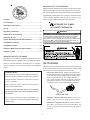
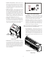
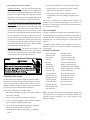
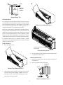
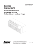
PACKAGE TERMINAL
AIR CONDITIONER/HEAT PUMP
INSTALLATION INSTRUCTIONS & OWNER’S MANUAL
Standard and Remote Applications with LED Control
ATTENTION INSTALLING PERSONNEL
As a professional installer you have an obligation to know the
product better than the customer. This includes all safety precautions and related items.
Prior to actual installation, thoroughly familiarize yourself with
this Instruction Manual. Pay special attention to all safety warnings.
Often during installation or repair it is possible to place yourself
in a position which is more hazardous than when the unit is in
operation.
Remember, it is your responsibility to install the product safely
and to know it well enough to be able to instruct a customer in
its safe use.
Safety is a matter of common sense...a matter of thinking before
acting. Most dealers have a list of specific good safety
practices...follow them.
The precautions listed in this Installation Manual are intended as
supplemental to existing practices. However, if there is a direct
conflict between existing practices and the content of this manual,
the precautions listed here take precedence.
This manual must be left with the owner of the equipment.
IO-723A
February 2011
is a registered trademark of Maytag Corporation or its related companies and is used under
license to Goodman Company, L.P., Houston, TX. All rights reserved.
5151 San Felipe, Suite 500
• Houston, TX 77056 • www.amana-ptac.com
© 2009, 2011 Goodman Company, L.P.
IMPORTANT NOTE TO THE SERVICER
Read this manual and familiarize yourself with the specific items
which must be adhered to before attempting to service this unit.
The precautions listed in this Installation Manual are intended as
supplemental to existing practices. However, if there is a direct
conflict between existing practices and the content of this
manual, the precautions listed here take precedence.
Contents
Unit Features .................................................. 2
RECOGNIZE THIS SYMBOL
Installation Instructions ..................................... 5
AS A SAFETY PRECAUTION.
Wiring ........................................................... 7
Operating Instructions ....................................... 8
W ARNING
Maintenance and Cleaning ................................ 12
G OO DMAN
WILL NO T BE RESPON SIBLE FOR A NY INJURY OR PROPERTY
Obtaining Service ........................................... 14
DAMA GE ARISING FR OM IMPR OPER SERVICE OR SERVICE PROCEDURES.
Normal Operating Sounds and Conditions ............. 14
RESPO NSIB ILITY F OR ANY PER SO NAL INJURY O R PROPERT Y DAM AGE WHICH
IF
YOU INSTALL OR PER FORM SERVICE ON THIS UNIT, YOU ASSUME
MAY RESU LT.
M ANY
JUR ISDIC TIONS REQU IRE A L ICENSE TO INSTA LL OR
SER VICE HEATING AND AIR C OND ITION ING EQUIPM EN T.
Configuration Settings ..................................... 14
Configuration Chart ........................................ 15
Diagnostic Maintenance & Status Report .............. 16
Diagnostic Codes ............................................ 17
IMPORTANT NOTE TO THE OWNER
This manual is to be used by qualified, professionally trained
HVAC technicians only. Goodman does not assume any respon-
UNIT FEATURES
sibility for property damage or personal injury for improper
service procedures or services performed by an unqualified
This unit has many features which are different than those found
person.
on conventional PTAC units. The servicer must be familiar with
these features in order to properly service the unit.
• LCDI or AFCI Power Cords - Underwriters Laboratories
and the National Electric Code (NEC) now require power
cords that sense current leakage and can open the electrical circuit to the unit on units rated at 250 volts or
less. In the event that unit does not operate, check the
reset button located on or near the head of the power
cord as part of the normal troubleshooting procedure.
IMPORTANT NOTES:
Your warranty certificate is also supplied with the unit.
Read the warranty carefully and note what is covered.
Keep the warranty certificate in a safe place, so you can
find it, if necessary.
Before using this manual, check the serial plate for
proper model identification.
THE INSTALLATION AND SERVICING OF THIS EQUIPMENT
MUST BE PERFORMED BY QUALIFIED, EXPERIENCED TECHNICIANS ONLY.
LCDI power Cord
Due to policy of continual product improvement, the
• Automatic 3-minute compressor lockout - After the com-
right is reserved to change specifications and design
pressor cycles off, it will not restart for three minutes.
without notice.
• Automatic 2nd stage electric heat - If the room temperature falls to 4°F below the set point temperature, the
reverse cycle heat is shut off and the electric strip heat is
turned on.
2
• Automatic freeze protection - Whenever power is supplied to the unit and the master switch is in the ON position, automatic freeze protection is active. If the unit
senses temperature below 40°F, the fan motor and electric strip heat are turned on. Freeze protection can be
turned off, if required.
• Random restart delay - To help eliminate power surges
after a power outage, the unit is equipped with a two to
four minute random restart delay feature. Whenever the
unit is plugged in with the master switch turned on and
the mode switch set in the cool or heat mode, a random
7 Button Touch Pad With Display
restart will occur. A random restart condition can be
• Load shedding - An LS terminal has been added for load
avoided by setting the mode switch in the fan only or off
shedding operations. If at any time a switch is closed
position before applying power to the unit.
between the LS and IN terminals, the compressor and elec-
• Fuse holder - On all 265 volt units, fuse holders are fac-
tric heater will lockout until the switch is opened.
tory installed. Check for blown fuse if unit does not operate. Fuse holder is located behind the front. Replacement
• Transfer fan - Terminals TF(-) and TF(+) on the low volt-
fuses may be purchased from the Parts Department or
age terminal board allow for an external (transfer) fan
contact your sales representative for part numbers.
connection. A user-supplied relay is required and, depending upon the type used, an approved external transformer kit may be required for installation.
NOTE: The PTAC Wire Harness Kit (PWHK01C) is required when
using either the transfer fan or load shedding option.
• Front mounting hole - A mounting hole location is provided to give the owner the option of securing the front to
the chassis. The mounting hole must be drilled at the
dimple indicating the correct location below a louver. The
owner must supply one 1/2 inch long #8 sheet metal screw
FUSE
HOLDERS
per unit. The screw must be removed before the front can
be removed.
Control Panel
• Indication LEDs - The touch pad has LEDs that correspond
to fan operation and to indicate unit status. The LEDs
next to the selections OFF, COOL, and HEAT indicate which
operational mode is active. The LED located in the lower
left corner is a status LED. This LED indicates the status of
the unit. See Diagnostic Maintenance & Status Report section for further details.
Front Mounting Screw accessed
through louvers.
Chassis Front
3
• Energy Management System Features
b. Original paid freight bill or indemnity in lieu thereof.
Temperature Setback - This option can save energy dol-
c. Original invoice or certified copy thereof, showing
lars for unrented or unoccupied rooms by automatically
trade and other discounts or reductions.
setting back the operational temperatures. This mode of
d. Copy of the inspection report issued by carrier’s
operation is selected through the configuration routine
representative at the time damage is reported to the
(see Configuration Settings section). NOTE: Temperature
carrier.
setback does not work with a wired remote thermostat.
The carrier is responsible for making prompt inspection of
Door Switch and Motion Sensor Low Voltage Terminals (DS1,
damage and for a thorough investigation of each claim. The
DS2, MS1, MS2) - The door switch and motion sensor oper-
distributor or manufacturer will not accept claims from dealers
ate as a unit, the door switch terminals allows for wired
for transportation damage.
connection of a door sensor to the control board. The
motion sensor interprets any door movement as a signal
UNIT ACCESSORIES
of occupancy. If the switch between DS1 and DS2 is closed,
This unit is designed for through-the-wall installation in new or
the door control will interpret the room door as closed. If
existing buildings. To complete the installation of this PTAC, an
the switch between MS1 and MS2 terminals is opened (or
insulated wall sleeve and an outdoor grille (either the stamped
closed if unit is configured for normally open) the control
aluminum grille, the architectural grille or polymer grille) are
will interpret the action as a signal of occupancy. If thirty
required.
minutes pass without any door activity, Energy Manage-
The chassis and the cabinet front are shipped in one carton.
ment Temperature setback activates.
Optional accessories to complete a particular installation are
Serial Port Interfaces - Two serial ports located on the
the following:
control board provide easy access for two-way communi-
OPTIONAL ACCESSORIES
cations to the control board from an optional RF antennae
can be attached for wireless communications.
TRANSPORTATION DAMAGE
All units are securely packed in shipping containers tested
according to International Safe Transit Association specifications. The carton must be checked upon arrival for external
damage. If damage is found, a written request for inspection
Power Switch Kit
Wire Harness Kit
Wall Sleeve Kit
Circuit Breaker Kit
Key Lock Kit
Architectural Grille Kit
Drain Kit
Remote Escutcheon Kit
Filter Kit
External Transformer Kit
Subbase Kit
Water or Steam Valve Kit
Hard Wire Kit
Condensate Disposal Pump Kit
Main Duct Kit
Remote Temperature Sensor Kit
Power Vent Kit
Wireless RF Antenna
Leveling Legs Kit
Wireless RF Thermostat
Hydronic Heat Kit
Wireless Motion Sensor
Stamped Grille Kit
Wireless Door Switch
Curtain Guard Kit
Wired Motion Sensor
Polymer Grille Kit
Wired Door Switch
Extension Duct Kit
Extra Deep Sleeves
Wall Thermostat Kit
by the carrier’s agent must be made immediately.
Fuse Holder Kit
In the event of damage, the consignee must:
1.
NOTE: Consult sales literature for the appropriate voltage and
Make notation on delivery receipt of any visible damage to
amperage selections, if applicable. For additional details and
shipment or container.
2.
Notify carrier promptly and request an inspection.
3.
In case of concealed damage, carrier should be notified as
illustrations of the accessories, refer to the Architect’s and
Engineer’s Manual.
soon as possible—preferably within 5 days.
4.
File the claim with the following supporting documents
within the 6 month statute of limitations.
a. Original Bill of Lading, certified copy, or indemnity
bond.
4
INSTALLATION INSTRUCTIONS
Sleeve
Stiffener
To ensure that the unit operates safely and efficiently, it must
be installed, operated and maintained according to these installation and operating instructions and all local codes and ordinances or, in their absence, with the latest edition of the
National Electric Code. The proper installation of this unit is
described in the following sections. Following the steps in the
order presented should ensure proper installation.
Wall Sleeve with Stiffener
Rear Closure
Panel
Flaps
Stiffener Removal
SLEEVE STIFFENER AND REAR CLOSURE PANEL
REMOVAL
Before the chassis can be installed in the wall sleeve, the sleeve
stiffener and the rear closure panel must be removed.
1.
Remove the zigzag folded cardboard sleeve stiffener.
2.
Remove the rear closure panel by folding the four flaps.
3.
Grasping the top and bottom flanges of the rear closure
Rear Enclosure Panel Removal
panel pull the entire panel out diagonally from one side.
DRAIN KIT INSTALLATION (OPTIONAL ACCESSORY)
During normal reverse cycle heating operation, condensate
water will drain out of the rear of the wall sleeve. If this
water is objectionable, a drain kit should be installed. The
drain kit has provisions for draining the water from either the
right or left side of the sleeve externally or from the bottom
SLEEVE INSTALLATION
of the sleeve internally. The drain kit must be installed
In order for condensate water to drain properly inside the
before the outdoor grille is installed. Refer to the Installation
unit, the sleeve must be installed properly:
Instructions supplied with the drain kit for a complete
• Level from right to left.
description of the installation procedure.
• A slight downward pitch from the indoor side to the outdoor side as shown below.
Refer to the Installation Instructions supplied with the PTAC
wall sleeve for a complete description of the installation
procedure.
5
Inside
Outside
Wall
Sleeve
Level
1/4 Bubble
Tilt To
Outside
Outside
Wall
Proper Sleeve Tilt
OUTDOOR GRILLE
An outside grille must be installed to direct air flow for proper
unit operation and also protect the outdoor coil. The grille must
be installed before installing the chassis. Refer to the Installa-
Cabinet Front Removal View 2
tion Instructions supplied with the outdoor grille kit for a
complete description of the installation procedure.
This model requires either a Stamped Grille Kit (Model SGK--B),
a Polymer Grille Kit (Model PGK) or an Architectural Grille Kit
(Model AGK--B). When replacing an old chassis with an existing
grille or using a specialized grille in a new installation, please
check with your sales representative to determine if the new
chassis should be used with the non-standard specialized grille.
An improper outdoor grille can decrease cooling or heating
capacity, increase energy usage and shorten compressor life and
possibly void the warranty.
FRONT REMOVAL
1.
Grasp the cabinet front.
Front Mounting Screw accessed
through louvers.
Front Mounting Screw
3.
Lift the cabinet front off the chassis. Reverse this procedure
to reinstall the cabinet front.
CHASSIS INSTALLATION
1.
Remove the cabinet front from the chassis as described in
Front Removal.
2.
Insert the chassis into the wall sleeve.
Wall Sleeve
Chassis
Cabinet Front Removal View 1
2.
Pull the bottom of the cabinet front away from the chassis
until the retaining clips disengage. NOTE: If front is secured with a screw, remove front mounting screw, then
follow front removal procedure.
Slide Chassis In
Outside
Wall
Chassis Installation View 1
6
3.
Slide the chassis into the wall sleeve until the chassis
flanges contact the front edge of the wall sleeve.
Screws
(3 on each
side of unit)
Wall Sleeve
Chassis
Outside
Wall
Chassis Installation View 2
4.
Secure the chassis to the wall sleeve using three screws on
each side of the chassis to ensure a proper seal between
the chassis and the wall sleeve. The screws are supplied
in a plastic bag attached to the power cord.
IMPORTANT NOTES:
1.
The unit is equipped with a rubber grommet mounted com-
Cord connection to a wall socket is not permitted for 265-volt
pressor. These grommets are factory set and require no ad-
units. All 265-volt units must be hard wired using the hard wire
justment.
2.
3.
4.
kit or make use of the plug-in receptacle in the standard
If a standard subbase is used, be sure the right hand subbase
subbase.
cover is removed before the chassis is installed in the sleeve.
230/208V and 115V units are equipped with LCDI or AFCI power
On 230V, 30A units installed with an existing subbase, use
cords and can open the electrical circuit to the unit. In the event
the subbase cover extension kit.
the unit does not operate, check the reset button located on or
Check the indoor and outdoor grilles for obstructions to air
near the head of the power cord as part of the normal trouble-
flow. The unit must be located where curtains, furniture,
shooting procedure.
trees, or other objects do not block the air flow to and from
WARNING
the unit. If air is obstructed and/or deflected back into the
unit, the air conditioner compressor may cycle on and off
THIS AIR CONDITIONER IS NOT MEANT TO PROVIDE UNATTENDED COOLING OR
rapidly. This could damage the compressor or possibly void
LIFE SUPPORT FOR PERSONS OR ANIMALS WHO ARE UNABLE TO REACT TO
the warranty.
THE FAILURE OF THIS PRODUCT.
THE FAILURE OF AN UNATTENDED AIR CONDITIONER MAY RESULT IN EXTREME
WIRING
HEAT IN THE CONDITIONED SPACE CAUSING OVERHEATING OR DEATH OF
PERSONS OR ANIMALS.
PRECAUTIONS MUST BE TAKEN TO WARN OFF OR GUARD AGAINST SUCH AN
OCCURRENCE.
PTAC WIRE HARNESS KIT (PWHK01C)
See PTAC Wire Harness Kit Installation Instructions for proper
wire orientation and location for low voltage wiring.
HEATERLESS UNITS
If a heaterless unit is ordered, field provisions must be made for
adding supplemental heat. Refer to the Installation Instructions
supplied with the kit for a complete description of the installation procedures. All 208/230 volt heaterless units are shipped
with a 15 Amp power cord.
7
Please refer to the Maintenance and Cleaning section for the
VOLTAGE MEASUREMENTS
proper cleaning procedure. If this light is still on after cleaning,
Once the unit is properly wired, measure the unit supply voltage.
please refer to the Diagnostic & Status Report section for
Voltage must fall within the voltage utilization range given in
assistance.
Table 2.
Operating Voltage
Unit Voltage
Rating
230/208
265
115
Voltage Utilization Range
Minimum
Maximum
197
253
238
292
103.5
126.5
Table 2 - Operating Voltage
OPERATING INSTRUCTIONS
USERS CONTROLS
Touch Pad With Display User Controls
A 7 button touch key pad, located behind the control door,
controls both temperature and operation mode. The key pads
can be used alone or in combination.
THERMOSTAT SETTING
SW2
AUXILIARY
P10
P12
7 BUTTON TOUCH PAD WITH DISPLAY
M1
DS1 DS2 MS1 MS2 EH IN LS FD1 FD2 TF- TF+ C
REMOTE THERMOSTAT
R GL W2 Y/W1 B GH
ON / OFF
MASTER SWITCH
Pressing the COOL thermostat control and the up or down arrows
P13
M2
COM A
IAT
BLACK
Control Board User Inputs*
will provide a cooler room temperature. Pressing the HEAT
thermostat control and the up or down arrow keys will provide
*NOTE: The PTAC Wire Harness Kit (PWHK01C) is required for
a warmer room temperature.
the auxiliary or remote thermostat options.
LCDI OR AFCI POWER CORD
ADDITIONAL CONTROL INPUTS
230/208V and 115V units are equipped with LCDI or AFCI power
The control inputs shown above provide additional unit control
cords and can open the electrical circuit to the unit. In the event
and features. To access these control inputs, the cabinet front
the unit does not operate, check the reset button located on or
must be removed (see Front Removal).
near the head of the power cord as part of the normal troubleshooting procedure.
MASTER SWITCH
The master switch disconnects power to all of the system
FAN SPEED
components.
The fan speed touch key will deliver high, low or auto fan speed
When this switch is in the off position, the
compressor, fan motor, reversing valve, and electric resistance
to circulate room air. NOTE: The AUTO selection will not be
heater will all be de-energized.
available if a fan speed is selected without COOL or Heat
selection.
Fan Operation HIGH or LOW with HEAT or COOL mode selected
- The selected fan speed shall run in the selected speed.
Fan Operation AUTO with HEAT or COOL mode selected - The fan
will run in low and high speed. The changes in fan speed are
automatic.
DIAGNOSTIC LIGHT
The green diagnostic light located in the lower left hand corner
of the touchpad and indicates operation warnings. This light
usually indicates that either the filter or coils need cleaning.
8
REMOTE CONTROL INPUTS
The C, R, GL, W2, Y/W1, B/O, and GH terminals provide control
inputs for a “manufacturer-approved” remote wall mounted
thermostat. The “B” terminal can be configured to become “O”
if needed see Configuration Settings For remote control thermostat operation, refer to the Remote Thermostat Operation
section.
FRONT DESK CONTROL (FD1, FD2, EH, IN)
The FD1, FD2, EH and IN terminals provide control inputs for a
front desk switch. Shorting across the FD1 and FD2 terminals will
disable unit operation. The only control function which will
remain active when these terminals are shorted is freeze protection. Any switch which will produce a short circuit across these
two terminals can be used as a front desk switch. The contact
resistance of the switch, when closed, must be less than 200
ohms for the front desk feature to operate properly. Table 3
shows the maximum wire length and corresponding gage size for
No holes are permitted in chassis basepan or
wallsleeve when routing low voltage wire. Route the
low voltage wires through the indention on the front
of the basepan.
installation of a front desk switch. The following figure shows a
wiring schematic for connecting the front desk switch to the
unit.
Low Voltage Wires Routing
If the unit is configured for wired unrented setback energy
management (see Configuration Settings section c2), EH and IN
VENT CONTROL
terminals are used instead of FD1 and FD2. If EH and IN are
The vent control allows outside air to be drawn into the
shorted, the unit will go into setback temperatures for cooling
conditioned area. This outside air can provide ventilation when
and heating as configured in c3 and c4 (see Configuration
the blower is operating, but it will increase the heating or
Settings). Unit operation will be disabled. “Fd” (see Diagnostic
cooling load and operating costs.
Codes) will appear on the display. This allows the room to quickly
recover to a comfortable temperature when the room is occu-
To obtain access to the vent control:
pied.
1.
Remove the cabinet front (see Front Removal).
2.
Remove the shipping screw (if installed) from the vent door.
3.
Remove the label (if present) from over the vent control
lever on the left side of the chassis. Remove the vent door
shipping screw.
Maximum Wire
Length
Wire Size Maximum Length
(AWG)
Allowed
#24
400 ft
#22
600 ft
#20
900 ft
#18
1500 ft
#16
2000 ft
Table 3 - Maximum Wire Length for
Front Desk Switch
AUXILIARY
DS1 DS2 MS1 MS2 EH IN LS FD1 FD2 TF- TF+ C
REMOTE THERMOSTAT
R
GL W2 Y/W1 B
GH
M2
IAT
BLACK
FRONT
DESK
SWITCH
Front Desk Switch Wiring Schematic
9
Use the following procedure to change the angle of the discharge
air flow:
Vent
Control
Lever
1.
Remove the front cabinet (see Front Removal).
2.
Position the front so that the backside is accessible.
Discharge Air Flow
3.
Vent
Control
Remove the four (4) screws which secure the discharge air
grille to the cabinet front.
Location of 4 Screws
Vent Door
Shipping Screw
Vent Control Lever
4.
Rotate the vent control lever to either open or close the
damper.
Discharge Air Flow Grille Removal
4.
Rotate the grille 180° clockwise.
5.
Reinstall the screws securing the discharge air grille to the
cabinet front. Reinstall the cabinet front on the unit.
Vent
Open
REMOTE THERMOSTAT
Vent
Closed
To operate this unit with a “manufacturer-approved” remote
thermostat, configure the control to be operated by the remote
Vent Door Lever Positions
thermostat. Enter configuration mode C1 and then select option
Hydronic Heat Installations
Code L5 (see Configuration Settings in back of manual).
To avoid the risk of freezing the steam or water coil during
in the remote mode, the unit will only respond to the thermostat
When
prolonged shut down periods, the vent door must be left closed
inputs (terminal strip positions GL (or GH), W2, Y/W1, and B*
when the outdoor temperature might fall below freezing.
shown in “Control Board User Inputs” illustration). NOTE: Once
configuration C1 with option code L5 has been selected, the
AIR DISCHARGE GRILLE
control touchpad will no longer accept inputs other than configu-
The discharge grille can be adjusted to expel air at either a 16°
ration and diagnostics modes. The room occupant must operate
or 56° angle.
the unit at the remote mounted thermostat.
NOTE: In remote mode, the 3-minute compressor time delay, the
random restart feature and the freeze protection feature are all
active (see Unit Features section).
THERMOSTAT LOCATION
This unit is designed to be operated with remote wall mounted
16°
Discharge
Air
56°
Discharge
Air
thermostats. For further information on thermostats approved
for use with this unit, contact your sales representative.
For best performance results, the thermostat should be located
approximately five feet above the floor on a vibration free,
inside wall in an area with good air circulation.
Discharge Grille Orientation Options
10
Do not install the thermostat where it may be affected by the
following:
ADDITIONAL NOTES:
1. For heat pump operation, a room thermostat with a B (heating change over) terminal or an O terminal (cooling change
• Dead spots behind doors, in corners or under cabinets
over) is required. This will mean that some “auto changeover”
• Hot or cold drafts from air ducts
thermostats cannot be used, as many of them either do not
• Radiant heat from the sun, appliances, or fireplaces
have a B terminal, or else energize the B terminal continu-
• Concealed pipes and chimneys
ously when in the “auto” position.
• Unheated (uncooled) areas behind the thermostat, such
as an outside walls
Consult the instruction sheet packaged with the thermostat for
further details on mounting and operation.
2.
Additional wiring should be run for future changeover to Heat
3.
Run 6 to 8 wires during initial installation. Tape or cap off
Pump or thermostat options.
any unused wires.
NOTE: Using a thermostat with an O terminal will require that
REMOTE THERMOSTAT OPERATION
Approved thermostats vary slightly in construction and, with few
exceptions, are operated similarly. The following operational
the 7 button with display control be configured (see Configuration Settings).
description pertains to approved nonprogrammable thermostats
AUXILIARY
REMOTE THERMOSTAT
LS FD1 FD2 TF- TF+
C
R
W2
DS1 DS2 MS1 MS2 EH IN
G*
that energize G in Heat and Cool mode.
GL W2 Y/W1 B
GH
HEAT/OFF/COOL Switch
• OFF - cooling and heating functions are defeated.
• HEAT - the selected room temperature is maintained by
cycling either in the heat pump mode or electric strip
Control Board
Connections
X1
O
B**
Y
electric strip heat when the coil temperature is 20°F or
W1
R
heat. A PTH unit is switched from the heat pump mode to
Thermostat
Connections
when the heat pump cannot keep up with the heating load
Wiring Schematic for Straight Cool Unit
and a two stage thermostat is used.
• COOL - the selected room temperature is maintained by
*NOTE: For high speed fan operation, connect “G” to “GH”.
cycling the air conditioner.
REMOTE THERMOSTAT
LS FD1 FD2 TF- TF+
C
R
W2
respective unit functions. The following wiring schematic illus-
AUXILIARY
DS1 DS2 MS1 MS2 EH IN
G*
Table 4 summarizes the thermostat input combinations and the
GL W2 Y/W1 B
GH
trations show wiring schematics for heat pump and straight cool
units with electric resistance heat, respectively.
Unit Function
GL*, W2
n/a
GL*, Y/W1, B**, O
GL*, Y/W1
X1
Stage 2
O
Stage 1 GL*, Y/W1, B**, O GL* Y/W1, B**, or GL*, W2, O
B**
NONE
Y
COOL
NONE
Control Board
Connections
W1
HEAT
Electric Heat
Thermostat
Input
R Terminal to:
R
OFF
Heat Pump
Thermostat
Input
R Terminal to:
Thermostat
Connections
Wiring Schematic for Remote Heat Pump
*NOTE: For high speed fan operation, connect “G” to “GH”.
*or GH depending on speed required
Table 5 shows the maximum wire length and corresponding gage
**If configured, B and O can be used interchangeably.
size for installation of a remote thermostat.
Table 4 - Remote Control Inputs
NOTE: The PTAC Wire Harness Kit (PWHK01C) is required for
remote thermostat options.
NOTE: If configured, B and O input terminals can be used interchangeably.
11
Maximum Wire
Length
Wire Size Maximum Length
(AWG)
Allowed
#24
400 ft
#22
600 ft
#20
900 ft
#18
1500 ft
#16
2000 ft
1.
Grasp each filter by its molded handle, located on the front
edge of the front, below the discharge grill.
2.
Pull the filter straight up and remove.
3.
Clean filter with vacuum or with running water.
Reverse this procedure to reinstall the filters.
Filters are removed by grasping
the filter’s top and gently pulling up
Table 5 - Maximum Wire Length for Remote
Control Connection
Front removal
is not necessary
to remove
the filters
Filter
Locations
MAINTENANCE AND CLEANING
Intake Filter Removal
Vent Screen
Before cleaning the vent screen, disconnect power to the unit by
unplugging the power cord at the wall outlet or subbase, or
disconnect power at the fuse box or circuit breaker. If unit is
operated with vent door closed, the vent screen does not need
to be cleaned.
WARNING
SOME LOCAL CONDITIONS AND ENVIRONMENTS CAN CAUSE FUNGI AND OTHER
MATERIAL TO GROW INSIDE THE PTAC UNIT. THIS MATERIAL WHEN DRIED,
1.
Remove the cabinet front as described in Front Removal.
2.
Remove the six screws securing the chassis to the wall sleeve.
3.
Slide the chassis out of the wall sleeve far enough so that
the vent screen is accessible.
AS WELL AS OTHER FOREIGN MATERIAL, SIMILAR TO DRYER LINT IN YOUR
CLOTHES DRYER, ARE FIRE HAZARDS.
BE SURE TO THOROUGHLY CHECK
AND
4.
CLEAN THE UNIT'S COILS, BLOWER WHEEL AND BASEPAN PER THE
Clean the vent screen, slide the chassis back into the wall
sleeve, secure it in place with six screws and reinstall the
INSTRUCTIONS CONTAINED IN THIS MANUAL.
front cabinet.
MONTHLY MAINTENANCE AND CLEANING
Intake Air Filters
To properly maintain the operational performance of your PTAC
unit, it is extremely important that the inlet air filters be
cleaned once per month or more often if operated in dusty or
dirty locations or conditions.
The intake air filters are con-
structed of durable polypropylene. The “air intake” air filters
can be easily inserted into the cabinet front using the cabinet
filter guides. Before cleaning the intake filter, turn the unit off
by setting the mode switch to the OFF position. Filter should be
cleaned as required.
The following procedure is used to remove the intake
filters:
Vent - (Left Side Unit)
12
1.
Cabinet Front
Create a water-tight seal by tightly covering the entire
The cabinet front and discharge air grille can be cleaned with a
control panel area and fan motor with plastic. Creating
water dampened cloth. Under no circumstances should hydro-
this seal prevents water from entering the control area or
carbon-based cleaners (e.g. acetone, benzene, naphtha gaso-
the fan motor and damaging the unit.
line, etc.) or ammonia based cleaners be used to clean the
2.
front or air grilles. Use care when cleaning the control area.
Spray condenser coil and basepan down with water. Next
spray a mild biodegradable detergent such as Simple
Green™ onto the condenser coil and basepan. Let set for
YEARLY MAINTENANCE AND CLEANING
five (5) minutes.
NOTE: Use a mild biodegradable detergent such as Simple
3.
Green™ when cleaning the unit. Special care must be taken to
Rinse condenser coil and basepan with water again.
NOTE: Ensure water pressure is no higher than that of an
protect the unit’s control board and other electrical components
ordinary garden hose and the water temperature no higher
from getting any water on them while cleaning. The use of harsh
than 120°F.
or caustic cleaning agents or materials such as bleach or coil
4.
cleaners that are not designed for PTAC products will cause
Tilt the non-compressor side of the unit up no higher than
damage or deterioration of the aluminum fin or coil material and
45 degrees and allow water to drain out the other side of
is not recommended. Care must be taken not to bend the
the unit.
aluminum fin stock.
5.
Remove excess water left in the basepan by wiping the
basepan with a dry cloth.
Routine Scheduled Maintenance
6.
To achieve continuing top performance and high efficiency,
Remove the water-tight seal from the motor and control
panel area.
establish a “once a year” cleaning/inspection schedule for the
unit. Take the unit out of the sleeve and thoroughly clean and
rinse. Be sure to include in the yearly cleaning the evaporator
coils, and condenser coils, basepan, and drain passages. Sched-
7.
Reinstall unit back into wall sleeve.
8.
Allow unit to dry for 24 hours before reapplying power.
When power is reapplied test unit for proper operation.
uled maintenance can be accomplished by either qualified local
9.
maintenance staff or by an authorized servicer. They must
Place a non-acidic algaecide in the basepan to inhibit bacteria growth. Ensure the algaecide is compatible with wet
follow the instructions described in this manual.
coil operation and is not corrosive to the coil.
Adverse Operating Conditions Maintenance
Units operating in dusty or corrosive locations; i.e. dusty con-
CAUTION
struction site or sea coast, must be cleaned more often. A
minimum of four (4) times a year will maintain proper opera-
HIGH PRESSURE AND HIGH TEMPERATURE CLEANING IS NOT RECOMMENDED.
DOING SO COULD DAMAGE THE ALUMINUM FIN STOCK AND ELECTRICAL
tional conditions and protect unit components.
COMPONENTS.
Wall Sleeve
Clean the wall sleeve while cleaning the unit. The caulking
Clearance Check
around the sleeve should be checked to make sure that any
Clearances around the unit should also be checked to make sure
potential air and water openings around the sleeve are properly
that the intake air and discharge air paths have not become
sealed. The wall sleeve’s level should also be rechecked. Proper
blocked or restricted. A minimum of eight inches clearance is
leveling for most installations are a ¼ bubble tilt to the outside
needed from unit to furniture , beds, or other objects for proper
and level from right to left. Contact your sales person for
operation. Restricted discharge or intake air will reduce the
detailed maintenance or cleaning instructions.
unit’s operational performance. In severe airflow restrictions
damage can occur to unit components such as the compressor,
Basepan and Condenser Coil
electric heater or fan motor.
CAUTION
DO NOT USE COMMERCIAL GRADE COIL CLEANERS. SOME OF THESE
ETHYLENE DIAMINE TETRACETIC ACID (EDTA)
CLEANERS MAY CONTAIN
WHICH CAN SHORTEN THE LIFE OF THE CONDENSER COIL.
Before cleaning the basepan and condenser coil, turn OFF unit
mode switch and disconnect power to the unit. To disconnect
power, either unplug the power cord at the wall outlet or
subbase, or disconnect power at the fuse box or circuit breaker.
13
CONFIGURATION SETTINGS
OBTAINING SERVICE
In the event this unit requires repair or servicing beyond what is
covered in this manual, contact an authorized service organization.
7 BUTTON TOUCH PAD WITH DISPLAY
The control can be configured to operate a wide range of
options. The options listed below with the * are the factory
default settings. If these are acceptable, then the unit does not
require any additional configuration and is fully operable. To
To obtain an authorized servicer, contact your sales representative or agency.
configure the unit, first select the configuration feature
code setting and then an option code to change from the
factory default setting.
NORMAL OPERATING
SOUNDS AND CONDITIONS
To enter configuration feature mode:
Water trickling sounds
Water is picked up and distributed over the coil. This
improves the efficiency and helps with water removal.
1.
Press and hold the up and down
arrow keys at the
Water dripping
same time and press the OFF
Water will collect in the base pan during high humidity days.
This can cause overflow and drip from the outside of the unit.
two (2) second time frame. The display will indicate - -.,
Air sounds
and then release the
The fan cycle switch sets the operational mode of the fan in
the ON position. The fan will run continuously whenever
power is applied in this mode. In the AUTO position, the fan
will cycle on and off with the compressor or electric heater.
key twice within a
key and press the
key one
time. The display will then alternate between C1 and 0.
To select a different configuration feature code, press the
Starting delay
HEAT
You may notice a few minutes delay in the starting if you
try to restart the unit too soon after turning it off or if you
key until the desired configuration comes
up. To scroll to a previously viewed configuration codes
adjust the thermostat right after the compressor has shut
press the COOL
off. This is due to a built in delay to protect the compres-
key.
Once you have scrolled to the correct feature, then to select the option code for your desired configuration, press
sor.
either the up or down key
to scroll through the op-
tions of the selected feature code.
To exit configuration mode:
1.
Press the OFF
key. Configuration feature mode
will also exit if no keys are pressed for a period of two
(2) minutes.
14
CONFIGURATION SETTINGS CHART
Configuration Code
Description
Option Code
Description
C1
Interface
0*
Chassis Membrane*
rE
Wireless Remote
L5
Wired Thermostat
bP
Button present
bA*
7-Button, reverts to Cyclic
A
Always run fan (even in Off)
bC
7-Button, reverts to Continuous
C
Cooler Only
H*
Heat Pump*
0
Service No Operation "Eo"
C2
C3
Fan Operation
Reverse Cycle Operation
C4
Room I.D. Digit 1 & 2
00* - 99
00* - 99
C5
Room I.D. Digit 3 & 4
00* - 99
00* - 99
C6
Wired or Wireless Occupancy
0*
Off*
1
On
18
18 Hour Automatic Entry
C8
Temp. Limiting Cool
60* - 72
60* - 72
C9
Temp. Limiting Heat
68 - 90, 80*
68 - 90, 80*
Cd
English / Metric Temp
F*
Fahrenheit Scale*
C
Celsius Scale
d6
Sensorless Un-Occ. Time
1 - 32, 18*
1 - 32, 18*
d7
1st Un-Occ. Set Back Temp.
1 - 16, 2*
1 - 16, 2*
d8
1st Un-Occ. Set Back Time
.1, .5*, 1 - 24
.1 ,.5 ,1 - 24, .5*
d9
2nd Un-Occ. Set Back Temp.
1 - 16, 3*
1 - 16, 3*
dA
2nd Un-Occ. Set Back Time
.1, .5, 1* - 24
(d8) - 24, 1*
db
3rd Un-Occ. Set Back Temp.
1 - 16, 6*
1 - 16, 6*
dC
3rd Un-Occ. Set Back Time
.1, .5, 1 - 24, 3*
(dA) - 24, 3*
dF
Jace Group Code
00* - 99
00* - 99
r4
Room Prefix
00* - 99
00* - 99
r5
Room Suffix
00* - 99
00* - 99
*Indicates factory default
See manufacturer for additional configuration options.
15
DIAGNOSTIC MAINTENANCE
& STATUS REPORT
ACTIVE FAILURES.
• If there are no active failures or lockouts, the display
will show a double dash, “- -”. If there is a code listed,
see the unit “Diagnostic Codes” chart for a list of definitions.
The Diagnostic Maintenance & Status Report provides detailed
information on PTAC control operation and operational status
including present modes, failures, airflow restriction warnings,
OPERATING TEMPERATURES.
operating temperatures, and past failures. The lower right
• If not in Diagnostic Status Report Mode, enter as instructed
hand dot on the center display flashes in this mode. In some
above and press the Fan Speed
cases the green LED located in the lower left hand corner of the
touchpad below the OFF key will also be lit. This Green LED
Fan Speed
“Status Light“ only illuminates if there is an status code that has
the wireless thermostat, rL; the indoor ambient tempera-
indicates that the indoor room filter is dirty should be cleaned
ture behind the filter, IA; the indoor coil temperature,
or replaced. NOTE: Dirty filters cause the unit to consume more
IC; the indoor discharge air temperature, Id; the outdoor
energy than normally needed to condition a room. Once the
coil temperature, OC; the outdoor ambient temperature,
filter has been cleaned or replaced, the LED should go out. If
OA; and the spare probe temperature, IH. If any of the
the LED is still illuminated after the filter has been cleaned,
probes are not populated the display will show the corre-
activate the Diagnostic and Status mode to view any active
sponding failure code.
codes. The unit may need additional cleaning or maintenance
of the evaporator or condenser coils. Please perform this step
PAST FAILURE LOG
before calling a servicer. A servicer should be called only if
• If not in Diagnostic Status Report Mode, enter as instructed
cleaning the filter or coils does not clear the status code or
above and press the Fan Speed
the code indicates that servicer should be called.
key twice.
• If already in Diagnostic Status Report mode, press the
DIAGNOSTIC STATUS REPORT MODE.
Fan Speed
key. While the display is showing oper-
ating temperatures, the last 10 failure codes active or
To enter Diagnostic Status Report mode, press and hold the
the COOL key
key. The display will show the tem-
perature of the desired set point, SP; the temperature at
been activated and should be reviewed. In most cases, this light
up and down
key.
• If already in Diagnostic Status Report mode, press the
past can be requested by pressing the Fan Speed
key again. The codes are displayed last entry first fol-
arrows and, while holding, quickly press
lowed subsequently by each preceding code.
twice.
Note that modes F1 and Fd are also displayed in the
normal control operation (see “Diagnostic Codes”
chart).
To exit Diagnostic Status Report mode, press the OFF
key.
16
DIAGNOSTIC CODES
STATUS
DISPLAY
ERROR
LIGHT
SUGGESTED ACTION
FP
Freeze Protection Engaged. The room temperature
measured by the wireless remote thermostat or indoor ambient
thermistor active sensor falls below 40°F.
Y
N
No Action required. This setting will disengage when the
room temperature rises above 43°F.
Fd
Front Desk switch is closed. All outputs are switched off.
Y
N
Open front desk switch to allow occupant unit operation.
Eo
Un-Configured Service Board All operation held awaiting configuration
Y
Y
Enter Configuration Menu and set "C3" to "C"
for coolers with electric heat or "H" for heat pumps.
EH
Emergency Hydronic Engaged. The EHH switch is closed.
Compressor is switched off.
Y
N
Open front emergency hydronic switch to allow occupant
unit operation.
LS
Load Shedding Engaged. The LS switch is closed.
Compressor and Electric heat is switched off.
Y
N
Open load shedding switch
to allow occupant unit operation.
On
Control is configured to respond to a wired thermostat
Y
N
No action if a wired thermostat is being used.
Otherwise, see Configuration Settings.
oP
Open Door Lockout
(DS1 & DS2 open; wireless)
Y
Y
Close Room Door.
Unit will not condition space with door open.
nP
Window Switch Lockout (LS & INN open)
Y
Y
Close Room Door or Window.
Unit will not condition space with door or window open.
hP
Heat Sentinel (WIAT > u3)
Y
N
No action required. This setting will disengage when
the room temperature falls.
Ur
Un-Rented Status
(EHH & INN or wireless)
Y
N
Front Desk needs to set to Rented mode (if applicable).
Y
Y
Replace black Indoor Ambient Thermistor or
Wireless Remote Thermostat.
MODES
CODE
F1
Indoor Ambient Thermistor reads outside the
range -20°F to 200°F & the wireless thermostat is not
communicating to the unit control or
REFRIGERATION
ALERTS
AIRFLOW
ALERTS
FAILURES
Indoor Ambient Thermistor (IAT) without a wireless remote
thermostat reads outside the range -20°F to 200°F.
F2
Wireless Remote Thermostat failure
N
N
Replace Wireless Thermostat.
F3
Indoor Ambient Thermistor reads
outside the range -20°F to 200°F
Y
N
Replace black Indoor Ambient Thermistor.
F4
Indoor Coil Thermistor either above
or below operating tolerances.
N
Y
Replace Red Indoor Coil Thermistor .
F5
Wireless Thermostat failure.
N
Y
Attempt to rebind Wireless Thermostat
or Replace Wireless Thermostat.
F6
Indoor Discharge Thermistor either above
or below operating tolerances.
N
Y
Replace Yellow Indoor
Discharge Thermistor.
Fb
Low Remote Battery Warning.
N
Y
Replace Batteries in Wireless Devices.
H1
High Voltage Protection engaged.
Power supply voltage is to high.
Y
N
Check for incoming power at correct voltage.
br
Brown Out Protection engaged.
Power was lost or voltage is low.
N
N
Check for incoming power at correct voltage.
L6
Discharge Air Too Hot.
N
Y
Clean Filter or Remove Air Blockage.
LC
Outdoor Coil Thermistor temperature high.
N
Y
Clean Condenser Coils, Check Fan for
fault. Code will reset after cleaning.
C2
Indoor Air Recirculation. Large delta between thermostat and
return.
N
Y
Clean Filter or Remove Air Blockage or Close
Vent Door or Improve indoor to outdoor seal.
C5
Outdoor Coil temperature too high for outdoor ambient
temperature.
N
Y
Check for Blocked Outdoor Air or Clean Coil.
C1
Indoor Coil is freezing up.
N
Y
Clean filter, Check for fan and blower operation,
Check for Refrigerant loss
or Restricted capillary tube.
C3
Indoor Coil is freezing up.
N
Y
Clean filter, Check for fan and blower operation,
Check for Refrigerant loss
or Restricted capillary tube.
C4
Indoor Coil froze up.
N
Y
Clean filter, Check for fan and blower operation,
Check for Refrigerant loss
or Restricted capillary tube.
C6
Poor Unit Performance.
N
Y
Check for blower motor, compressor,
or electric heat operation.
C7
Indoor Freezing Lockout (ICT - IAT > 20) +10 Min
N
Y
Clean filter, Check for fan and blower operation,
Check for Refrigerant loss
or Restricted capillary tube.
17
THIS PAGE INTENTIONALLY LEFT BLANK
18
THIS PAGE INTENTIONALLY LEFT BLANK
19
is a registered trademark of Maytag Corporation or its related companies and is used under
license to Goodman Company, L.P., Houston, TX. All rights reserved.
5151 San Felipe, Suite 500
• Houston, TX 77056 • www.amana-ptac.com
© 2009, 2011 Goodman Company, L.P.
20