1
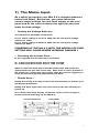
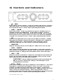
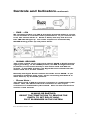
MA 2.2 TRUE CLASS A
MICROPHONE AMPLIFIER.
USERS MANUAL.
MA 2.2 USERS MANUAL VERSION-1, MARCH 2000. CONTENTS COPYRIGHT BUZZ AUDIO 2000.
PO BOX 6677, WELLINGTON, 6141 NEW ZEALAND. TELEPHONE 64+4+472-3084.
http://www.buzzaudio.com
email [email protected]
Welcome…
Thank you for choosing the Buzz Audio MA 2.2
True Class A Microphone Amplifier.
In this manual you will find important information
regarding the use of your MA 2.2 and we suggest that
you do read it before using the unit.
If after unpacking the MA 2.2 you find any damage you
should contact your dealer or supplier immediately for
advice on what to do.
We also suggest you retain the original packaging at
least during the warranty period in case you need to
return the unit for service, however we are confident this
will not be necessary!!
• Warm Up.
The Buzz Audio MA 2.2 utilises discrete Class A
amplifiers which take about 30 mins to warm up. We
suggest you keep the MA 2.2 switched on whilst in
regular use to ensure continuous sonic performance.
Contents…
1] The Mains Input
2] Connections
- page 2.
- page 3.
3] Controls and Indicators
4] Options
5] Tips
- page 4.
– page 6.
– page 6.
6] Service
– page 7.
7] Specifications
– page 7.
8] Internal Adjustments
– page 8.
9] Warranty Information
– page 10.
MA 2.2 USERS MANUAL VERSION-1 PAGE 1
1] The Mains Input.
As a safety precaution your MA 2.2 is shipped without a
mains fuse fitted. Before use, you must select the
correct mains voltage for your local supply on the rear
panel and fit the correct mains fuse type into the fuse
draw for that voltage.
•
Setting the Voltage Selector…
You will need a flat blade screwdriver.
If your mains voltage is 110V to 120V set the rear panel voltage
selector to 120V.
If your mains voltage is 220V to 240V set the rear panel voltage
selector to 240V.
POWERING UP THE MA 2.2 WITH THE WRONG VOLTAGE
SETTING MAY CAUSE SEVERE INTERNAL DAMAGE !!
•
Selecting the Correct Fuse…
In the supplied accessories bag you will find;
2x 1 Amp slow blow fuses, FIT for 220V to 240V.
2x 2 Amp slow blow fuses, FIT for 110V to 120V.
Slide out the fuse draw above the IEC power inlet and insert the
appropriate fuse into the carrier clip. Note there is also a position in
the carrier for a spare fuse (the square tube bit) and we suggest you
store the second supplied appropriate fuse here.
•
Please Note…
Fitting the wrong fuse may result in the fuse blowing on power up or
inadequate protection.
Fitting fast blow type fuses may also result in the fuse blowing on
power up.
Your dealer may have already set all this up for you but it pays to
check it before powering up the MA 2.2.
VOLTAGE SELECTOR
FUSE DRAW
MA 2.2 USERS MANUAL VERSION-1 PAGE 2
2
2] Connections.
•
Mic Input.
The MA 2.2 is designed as a balanced input microphone amplifier.
The connection of unbalanced sources is not recommended. The
XLR female style input connector is wired as follows;
Pin 1 = Signal Ground (common)
Pin 2 = Signal Hot (+)
Pin 3 = Signal Cold (-)
•
Output.
The MA 2.2 has two output connectors. In standard configuration
the output is unbalanced to avoid the extra amplifier stage required
and maintain the shortest possible internal signal path.
The XLR male style output connector is wired as follows;
Pin 1 = Chassis Ground
Pin 2 = Signal Hot (+)
Pin 3 = Signal Ground (common)
If the optional output transformer is fitted (see the section on
Options) the XLR is wired as follows;
Pin 1 = Chassis Ground
Pin 2 = Signal Hot (+)
Pin 3 = Signal Cold (-)
In both cases, the 3 pole ¼” jack socket always carries the
unbalanced output, as follows;
Tip = Signal Hot (+)
Ring = Signal Ground (common)
Sleeve = Chassis Ground
•
Please Note…
The Chassis Ground connection is intended for connecting cable
SHIELDS. When connecting the MA 2.2 output to other devices, it is
not always necessary to connect the shield at both ends of the
cable. This may help prevent earth loops occurring. The mic input
Signal Ground however is always connected at both ends to ensure
correct shielding of the cable and mic body.
The Signal Ground source can be selected HARD or SOFT, see the
Controls and Indicators section.
MA 2.2 USERS MANUAL VERSION-1 PAGE 3
3
3] Controls and Indicators.
•
O … REV
Input phase reverse switch. In the up position the input is in phase
with the output. In the down position the input phase is reversed.
It is normal to hear a “click” when operating this switch.
• 0dB … -20dB
Input attenuator. In the up position the gain of the MA 2.2 is as
marked around the GAIN knob. In the down position, a pad is
inserted at the input, reducing overall gain by 20dB. Use for high
level inputs such as drums when you can’t turn down the GAIN far
enough. It is normal to hear a “click” when operating this switch.
• PK
This led will light when the output of the MA 2.2 reaches +18dBu
indicating a possible overload condition. The MA 2.2 is capable of
+24dBu output level. The threshold of this indicator can be
internally adjusted, see the section on Internal Adjustments.
• GAIN dB
Adjusts the gain/volume of the MA 2.2. What more can we say?
• OUT … MUTE
This control mutes the MA 2.2 output when in the down position.
Very useful in avoiding loud “bangs” when you have to switch on the
phantom power or change the microphone input. Also read Tips.
• 48V … ON
Phantom power required for condenser microphones and active DI
boxes. In the down position, 48V is applied to pin 2 and 3 of the
input XLR connector via 6k8 ohm resistors.
CAUTION!! Always MUTE the MA 2.2 when switching the
48V on or off to avoid loud “bangs” and damage to your
loudspeakers and ears!!
• HI Z … LO Z
This control changes the input impedance of the MA 2.2. The input
impedance is what the microphone “sees” as a load. In the up
position, the MA 2.2 input impedance is 3k ohms. In the down
position the input impedance is 1k2 ohms. Which position to use??
This is purely a subjective thing. Some microphones such as
dynamic and older tube types may sound better in the LO Z position.
It is normal to hear a “click” when operating this switch.
MA 2.2 USERS MANUAL VERSION-1 PAGE 4
4
Controls and Indicators continued…
•
PWR … ON
We recommend that your MA 2.2 remains powered whilst in regular
use to maintain it’s excellent sonic performance. If you need to turn
it off, this switch will do it. Down is ON by the way and the cool
blue LED should light up. The audio outputs are automatically
MUTED during power up and power down.
• SIGNAL GROUND.
This rocker switch on the rear panel selects HARD or SOFT internal
signal grounding. In the HARD position, the MA 2.2 Signal Ground
(common) is connected directly to the mains earth and MA 2.2
chassis. In the SOFT position, the Signal Ground is lifted from the
mains earth via a 10 ohm resistor.
Normally the Signal Ground switch should be set to HARD. If you
experience problems with “hum” when connecting the MA 2.2 to
other devices, try the SOFT position.
• Please Note…
The mains earth to MA 2.2 chassis connection is unaffected by this
switch. Also, the Chassis Ground connection on the output
connectors is unaffected by this switch. Also see the Connections
section of this manual.
FOR SAFETY REASONS THE MA 2.2 SHOULD
ALWAYS BE EARTHED.
RESIST THE TEMPTATION TO REMOVE THE
EARTH TO GET RID OF HUM.
FIX IT ELSEWHERE IN THE SYSTEM.
MA 2.2 USERS MANUAL VERSION-1 PAGE 5
5
4] Options.
•
Output Transformer.
Mounting holes on MA 2.2 bottom panel behind the main channel
circuit board are provided for fitting a Sowter type 8403-A line
output transformer. Sowter transformers are made in England and
can be purchased on line at http://homepages.tcp.co.uk/~sowter/
Buzz Audio can also supply the transformers pre-fitted to the MA 2.2
or as a kit for retro fitting. Soldering is required to fit the output
transformer. For further information contact your dealer or Buzz
Audio.
•
Special Versions of the MA 2.2.
Some of the special options Buzz Audio can supply include;
• High gain versions.
• Different input impedances, eg 600 ohm.
• Electronically balanced output module using hi-quality operational
amplifiers instead of the transformer.
Contact your dealer or Buzz Audio for more information and pricing.
5] Tips.
•
Ensure the MA 2.2 has adequate ventilation. The Class A circuitry
does generate a fair amount of heat and the box will get warm.
Avoid racking next to high heat generating devices.
•
Avoid racking the MA 2.2 next to possible induced noise sources
such as power amplifiers or anything with a big power
transformer and equipment that uses large switching power
supplies like computers or VDU’s.
•
Remember the standard output is unbalanced, if you seem to be
getting no signal it may be that the MA 2.2 output is being
shorted by a reversed phase (pin 3 HOT) unbalanced input.
•
Avoid connecting/disconnecting microphones with the GAIN on a
high setting and/or with the 48V phantom switched on. Switch
the PAD to –20dB and MUTE the output. This will avoid huge
transients entering the amplifier front end.
•
Clean the MA 2.2 with a damp cloth and a little detergent. Do not
use solvents or isopropyl alcohol, it may damage the finish.
MA 2.2 USERS MANUAL VERSION-1 PAGE 6
6
6] Service.
Should you experience any technical problem with your MA 2.2,
contact your dealer or Buzz Audio for recommendations on what to
do. The modular nature of the MA 2.2 construction means most
electronic faults can be easily repaired by swapping circuit boards.
For on line support visit our web site; http://www.buzzaudio.com
Buzz Audio, Rear Entrance, 77 Kent Tce, PO Box 6677, Te Aro,
Wellington, New Zealand. Voice/Fax 64+4+385-2478.
Email; [email protected]
7] Specifications.
Min Gain;
+16dB (-4dB with pad in)
Max Gain;
+65dB
Max out level;
+24dBu (0dBu ref = 0.775mV)
THD;
100Hz 0.005%.
1kHz 0.005%.
10kHz 0.008%.
CMNR;
100Hz 80dB.
1kHz 80dB.
10kHz 70dB.
EIN;
-133.5dB (A wtg, 150 ohm source Z).
SNR;
-74dB (A wtg, input shorted)
BW;
2Hz to 250kHz @ 20dB gain.
20Hz to 250kHz @ 64dB gain.
20Hz to 40Khz with Output Transformer.
Input Impedance;
3k ohms/1k2 ohm switchable.
Power Requirements;
230/115 Volts selectable.
Package;
1U rack mount.
481W x 44.5H x 300D (mm).
Weight;
6kg
SPECIFICATIONS SUBJECT TO CHANGE WITHOUT NOTICE.
MA 2.2 USERS MANUAL VERSION-1 PAGE 7
7
8] Internal Adjustments.
•
The following information is provided should your MA 2.2 require
re-calibration. All adjustments are performed in the factory and
should not need re-adjustment unless the amplifier modules
and/or other components have been replaced. You may wish to
alter the PK LED threshold to a lower or higher setting.
PLEASE NOTE – If in doubt, do not attempt any internal
adjustments, seek technical help.
Trim Pot Locater.
MAXIMUM GAIN
adjust.
LOW FREQUENCY
CMNR adjust.
HIGH FREQUENCY
CMNR adjust.
PK LED threshold
adjust.
MA 2.2 Channel Card Top View
MA 2.2 USERS MANUAL VERSION-1 PAGE 8
8
Internal Adjustments
•
continued
Initial Setup.
See the previous page for the location of the trimmer pots. Set all
front panel switches (except for the PWR obviously) to the UP
position. Set the GAIN knob fully anticlockwise. The MA 2.2 should
be powered up for 1 hour before making adjustments. All
measurements are referenced to 0dBu = 0.775V RMS, (sometimes
called 0dBm).
•
Maximum Gain Adjustment.
Connect an audio voltmeter to the channel output to be adjusted.
Apply a –50dBu 1kHz balanced sine wave signal to the channel input.
Turn the GAIN knob fully clockwise and adjust the MAXIMUM GAIN
trimmer to obtain +15dBu at the output. This sets the maximum
gain of the MA 2.2 to 65dB.
•
PK LED Threshold Adjustment.
Connect an audio voltmeter to the channel output to be adjusted.
Apply a –20dBu 1kHz balanced sine wave signal to the channel input.
Adjust the GAIN knob to obtain +18dBu (or your desired threshold
level) on the audio voltmeter. Adjust the PK LED trimmer so that the
front panel PK LED just lights.
•
Low Frequency and High Frequency CMNR.
CMNR is the Common Mode Noise Rejection, the ability of the
amplifier to reject noise common to both “legs” of the balanced
input.
Connect an audio voltmeter to the channel output to be adjusted.
Apply a +10dBu approx 1kHz square wave signal to both PIN 2 and
PIN 3 of the channel input connector. Set the GAIN knob to the
51dB marked position. Adjust the LOW FREQ CMNR trimmer for a
minimum reading (dip) on the audio voltmeter.
Change the input frequency to 10kHz adjust the HIGH FREQ CMNR
trimmer for minimum reading on the voltmeter. Return to the 1kHz
input frequency and check the LOW FREQ adjustment, re adjust as
necessary. Finally, check the HIGH FREQ adjustment null whilst still
applying a 1kHz square wave input.
•
Problems ?
Contact your dealer or Buzz Audio.
MA 2.2 USERS MANUAL VERSION-1 PAGE 9
9
9] Warranty Information.
•
Disclaimer
Buzz Audio is not liable for any damage to microphones, amplifiers,
consoles, speakers or any other equipment and/or electric shock to
humans that is caused by negligence or improper installation and/or
use of the MA2.2 True Class A Microphone Amplifier.
•
Standard Product Warranty
Buzz Audio guarantees the MA2.2 True Class A Microphone
Amplifier to be free of defective materials and/or workmanship for a
period of 1 year (12 months) from the date of sale, and will replace
defective parts and repair malfunctioning products under this
warranty when the defect occurs under normal installation and use –
provided the unit is returned to our factory (or duly authorised
service centre) via prepaid transportation with a copy of the proof of
purchase, ie, sales receipt. This warranty provides that examination
of the returned product must indicate, in our judgement, a
manufacturing defect. This warranty does not extend to any
product that has been subjected to misuse, neglect, accident,
improper installation, or where the date code has been removed or
defaced. The standard warranty is NOT transferable.
•
Product Warranty Extension
The above Warranty may be extended to a period of 2 years (24
months) from date of sale provided the enclosed Warranty
Registration card is completed and returned to the office of Buzz
Audio within 4 weeks (28 days) from purchase date. Alternatively,
you may Register your purchase on-line at our web-site
www.buzzaudio.com. The Extended Warranty is transferable.
Your Dealer is…
MA 2.2 USERS MANUAL VERSION-1, MARCH 2000. CONTENTS COPYRIGHT BUZZ AUDIO 2000.
PO BOX 6677, WELLINGTON, 6141 NEW ZEALAND. TELEPHONE 64+4+472-3084.
http://www.buzzaudio.com
email [email protected]
MA 2.2 USERS MANUAL VERSION-1 PAGE 10
10